1. Introduction
In China, prefabricated steel structures have been widely built due to their environmental friendliness, sustainability, and low labor cost. A prefabricated building consists of factory-made components or units that are transported and assembled on-site. Prefabricated construction is the practice of assembling a variety of components of a structure at a manufacturing site and transporting the sub-assemblies to the construction site.
Previous studies have concluded that the effectiveness of prefabricated building policies (PBPs) significantly affects the promotion and performance of prefabricated buildings [
1]. In 2016, the General Office of the State Council, PRC issued the “Guiding opinions on vigorously developing prefabricated buildings,” striving to make it account for 30% of the new building area within ten years and also encouraging design companies and research institutes to develop design technology and universal software for prefabricated buildings. In 2019, the General Office of the State Council issued a policy which strives to promote the integrated application of BIM (building information modeling), big data, mobile Internet, cloud computing, IoT (Internet of Things), artificial intelligence, and other technologies in the whole process of design, construction, operation, and maintenance, to promote the delivery and application of digital achievements in engineering construction, and improve the information level of the construction industry. Furthermore, the “Outline of the National Informatization Development Strategy” proposed the “Internet+” action, is required to improve the informatization level of the construction industry. In conclusion, the deep integration of the industry will give full play to the leading and supporting role of informatization in the construction industry and reshape its new industrial state.
In this article, a BIM platform for the manufacture of a prefabricated steel structure is developed by cooperating with a manufacturing company of steel structures. The company is located in Taiyuan, Shanxi Province, China. Covering 346 acres, it specializes in the manufacture of prefabricated steel structures such as multi-layer steel frame structure, large-span spatial structures, bridge steel structures, and modular buildings. Moreover, this company focuses on civil construction, public construction, industrial construction, municipal engineering, overseas engineering, and other fields.
Many problems arise during the manufacturing process due to the unreasonable information flow, such as chaotic management, opaque component production process, and disability statistics of the manufacturing data. The quality issues of each production batch may not be sent to the foremen in time. Furthermore, the quantity of manufacturing components in each workshop is usually invisible. As a negative aspect, critical information of projects is often invisible, resulting in different stakeholders not grasping the manufacturing progress immediately. The well-formatted information of manufacturing components at the right time in the right process is still insufficient to raise the efficiency of collaborative working and decision making in manufacturing services further when adopting BIM in the prefabricated construction projects.
The aim of this study is to develop a BIM platform, which serves as a collaborative tool for steel structure factories, to visualize the manufacturing progress, track the manufacturing status of steel components, and reduce excessive information exchange. The BIM platform is developed by employing BIM as the necessary infrastructure to handle these challenges. Among the manufacture of prefabricated steel structures, BIM serves as the necessary concept for tracking the manufacturing process of components. It also serves a variety of working groups and decision-makers as a collaborative tool. In other words, each component’s manufacturing process could be traced and visualized in the 3D model to monitor progress, which can significantly reduce the waste of time and material during the process and improve the quality of components.
In the developed BIM platform, the geometry information, combined with manufacturing information, semantic information, and corresponding files, is used for the collaboration among different teams and real-time control of project manufacturing progress. The architecture of the BIM platform is based on the manufacturing process of the steel components to approach the actual functional and non-functional requirements to the maximum extent. The highlights of this study are that the developed platform can display each component’s manufacturing status in both 3D models and tables so that users can grasp the manufacturing progress immediately and sufficiently. Besides, additional data such as drawing files corresponding to each steel component and contracts of each project, are user-defined so that users can obtain them from the platform to reduce excessive information exchange. Finally, the visibility, traceability, and availability of manufacturing are also realized in this platform.
This article is organized as follows.
Section 2 is the literature review, which discusses the comparative research conducted by some researchers.
Section 3 explains the architecture design and development of the platform. The practical application of this platform in the manufacturing factory is presented in
Section 4. Finally,
Section 5 is the conclusion of this article.
2. Literature Review
2.1. The Development of BIM
BIM technology is one of the most cutting-edge fields in the architecture, engineering, and construction (AEC) industries. Through BIM technology, a virtual model of a building can be accurately constructed on a computer. The computer-generated model contains accurate geometric information and related component data that can be used to support construction, assembly, and procurement [
2]. BIM platforms can integrate with many technologies. For instance, the integration of BIM with IoT mainly focuses on four aspects: (1) construction operation and monitoring; (2) structural health and construction safety management; (3) construction logistics management; and (4) mechanical and electrical equipment management [
3].
From a global perspective, the use of BIM in several English-speaking countries is more common, including the United States, Canada, Norway, Finland, the United Kingdom, Denmark, Australia, and Singapore. One reason is that several mainstream BIM software company providers, such as Autodesk, Bentley, and Tekla, are located in these countries, so English facilitates the spread of BIM concepts. Daedal research [
4] concluded that the global BIM market is expected to reach 8 billion dollars, with an average annual growth rate of 13% between 2015 and 2020. In Europe, Finland, Norway, Denmark, and the Netherlands have adopted BIM for decades. In recent years, the United Kingdom has also begun to make efforts in BIM. The British Building Society (NBS) reported that the utilization rate of BIM in the United Kingdom increased from 13% to 30% between 2011 and 2016. The same goes for France, Germany, and Spain. Moreover, North America is the region with the fastest growth in BIM implementation. The construction utilization rate had increased from 28% in 2007 to 71% in 2012. In the United States, BIM has been widely employed by large public owners, such as the General Services Administration (GSA) and the United States Army Corps of Engineers (USACE), where BIM is required to be used in all major US projects. In 2003, GSA established a national 3D-4D-BIM plan, which requires that the original format and IFC (Industry Foundation Classes) format need be used to deliver results in all stages of project design. Furthermore, any necessary 2D floor plans can be derived from the results. Additionally, all GSA projects are encouraged to use mature 3D/4D BIM technology to the maximum extent possible and use BIM as a building lifecycle management tool to lead the development of the industry [
5].
Nowadays, several major companies have developed BIM software for different stages of buildings, such as Autodesk’s Revit [
6], Tekla’s Xsteel [
7] dedicated to steel structure design, ArchiCAD of Graphisoft company [
8], and various types of software of the Bentley company. In China, a few companies have also developed mature products, such as BIM software developed by Glodon [
9] and Luban [
10]. However, this type of software mainly focuses on modeling and has not yet reached the collaboration and integration of BIM technology applications.
Another critical application is BIM for heritage, which focuses on the conservation of heritage. Using digital methods, BIM for heritage has had a heavy focus on digital documentation of heritage assets fueled by technological developments in 3D data capture such as photogrammetry and laser scanning over recent years [
11]. For instance, Ruffino et al. [
12] and Sánchez-Aparicio et al. [
13] adopted 3D point clouds for the capture the 3D geometry of historic heritage for the conservation and visualization of building heritage.
2.2. BIM Platform
In modern AEC industries, data sets such as building geometry and topology data, sensor data, behavior data, geospatial information data are generated and consumed throughout the building’s life cycle. The integration of BIM and semantic web technologies can meet the requirements for storing, sharing, and using heterogeneous data sets [
3]. However, elements created in one BIM software may not successfully interact with another one with full functionality and complete data. If one considers how the design and construction works are carried out, it is understandable that during the exchange of files, any data loss, including material type, scheduling or phasing information, cost of elements, or 3D data related to fabrication and production, can be followed by loss of quality, ineffective teamwork, cost overruns, and time delays [
14].
The 4D theory was first proposed by CIFE (Center for Integrated Facility Engineering) of Stanford University in 1996, and then the CIFE 4D-CAD system was developed. The system corresponds to the 3D model of the structural components of the building with various tasks of the existing progress plan and dynamically simulates the change process of these components [
15]. In 2003, CIFE developed a new 4D product model (PM4D, Product Model, and Fourth Dimension) system. The system can quickly generate building cost budgets, construction progress, environmental reports, and building life cycle cost analysis. Moreover, it realizes 3D visualization of the product model and 4D construction process simulation through VR (Virtual Reality) technology. At present, CIFE is committed to applying the 4D concept to the entire AEC field, using advanced computing equipment and interactive tools to build a fully digital interactive room (IRoom) in which all parties involved in the construction can start collaborative work in real-time [
16]. The emergence of IRoom has revealed the development direction of the next generation of construction management tools. In 2017, Hamledari et al. [
17] from CIFE combined drones with image progress tracking and object detection technology with 4DBIM to detect the construction progress of the project.
To develop the web-based BIM platform, a stable and reliable server is essential. For example, the implementation of web-based BIM tools is mostly based on server platforms such as EDM Model Server [
18], IFC Model Server [
19], and BIMServer [
20] for secondary development. Besides, some commercial BIM platforms such as Autodesk BIM 360 [
21], cannot interact with third-party software due to ecological closure. Therefore, it cannot meet the individual needs of various roles of users.
In 2002, Wang et al. [
22] put forward an extended 4D construction management model through in-depth research on 4D technology (4D Site Management Model++, 4DSMM++). This model takes the Work Breakdown Structure (WBS) as the core, combining construction management elements, such as schedule, 3D model, resource management, site layout, and cost analysis to realize the visual management and optimization control of building construction, and the control of resources such as cost, schedule, materials, machinery, workforce, and site layout in each construction stage. The 4D-GCPSU (4D-Graphics for Construction Planning and Site Utilization) [
23], a building construction 4D project management system based on 4DSMM++, has been successfully applied to many actual projects in Beijing and Hong Kong, including the project management of the National Stadium for the Beijing Olympics [
24,
25]. The on-site assembly BIM platform for prefabricated components developed by Li et al. [
26] based on the IoT provides the installation of radio frequency identification (RFID) identifiers on components, uses GPS to realize component transportation, storage, and installation precision positioning, and displays them in a 3D model. This platform was used in the Tuen Mun project in Hong Kong.
Meanwhile, emerging technology such as AR (Augmented Reality) and VR (Virtuality Reality) can also be embedded into the BIM platform, providing a new way of interacting with the model and an engaging and immersive environment [
27]. For instance, Mehrdad et al. [
28] developed a BIM–AR quality management system for structural elements, with which users can inspect the internal structure of structural components at the construction site. Woodward and Hakkarainen [
29] developed a system that integrates BIM and VR with schedule information to visualize the construction progress in the 4D model.
2.3. Prefabricated Buildings in China
Over the past four decades, cities in China have experienced a rapid urbanization process with an increase in the urbanization rate from 17.4% in 1978 to 51.3% in 2011 (National Bureau of Statistics of China, 2012) [
30]. According to previous studies, the construction industry generates about 33% of the world’s carbon emissions and consumes about 40% of its total energy, 16% of its water, and 40% of its raw materials [
31]. The construction industry has a significant impact on sustainable development worldwide. Traditional construction methods are dominated by labor-intensive approaches involving the use of considerable on-site labor [
32]. Nevertheless, with the aging of the population in China, problems arise by the reduction of the labor force, and the shortage of technical construction workers has become more prominent. With the large-scale construction activities triggered by rapid urbanization, prefabricated buildings, which move a partially finished building from a construction site into a controlled component factory [
33], are actively promoted to achieve technological innovation in the construction industry, thereby solving the problems of labor shortage and environmental pollution. With its potential for capitalizing on the strengths of the manufacturing industry, prefabricated buildings have been widely considered to be the future of the construction industry worldwide [
34]. However, the collaborative issues among multiple companies and professional designer issues are an essential barrier during the design phase of prefabricated buildings. Therefore, a cross-professional collaboration platform and the training for professional designers are essential [
35].
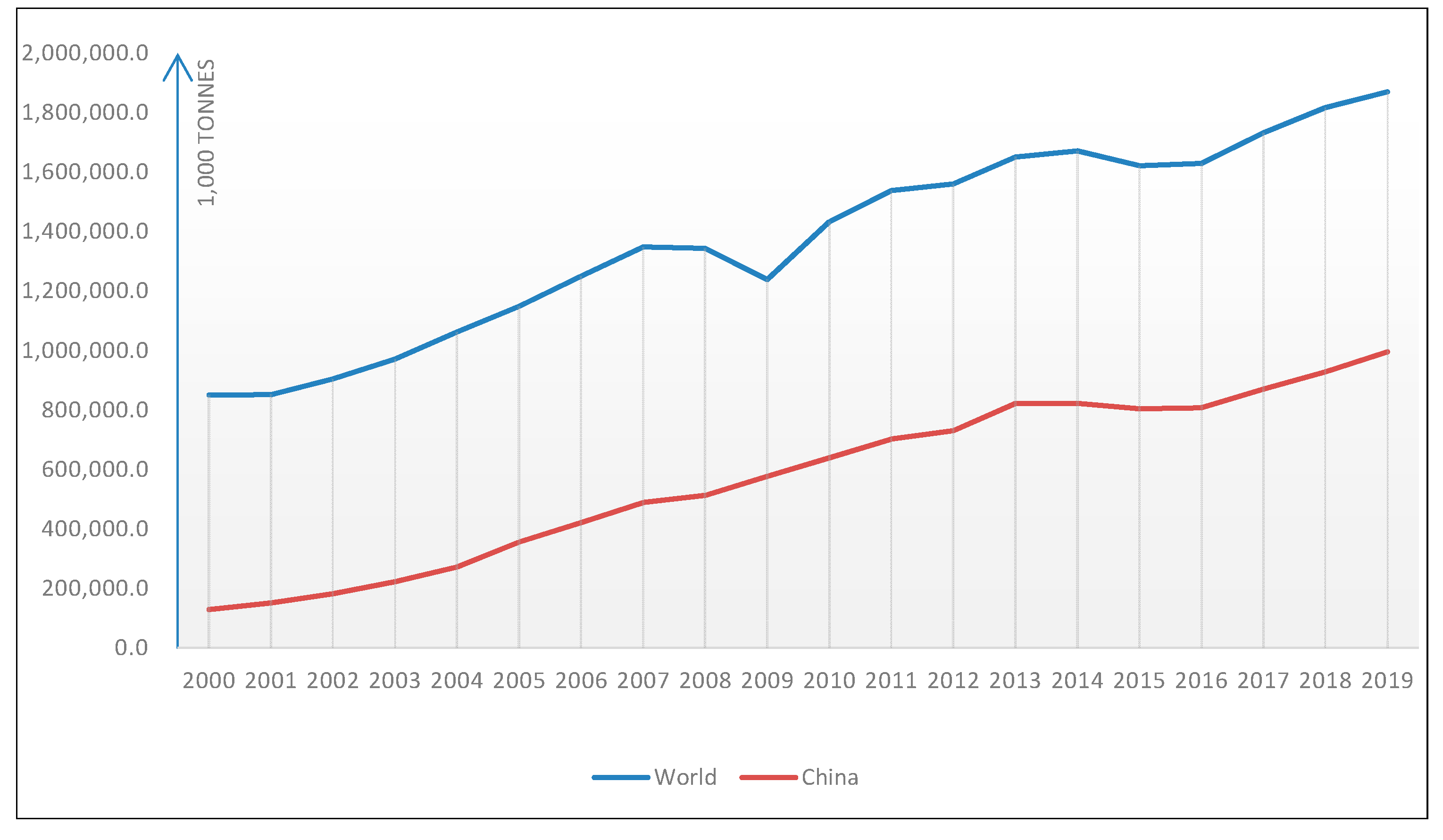
Besides, as shown in
Figure 1, China’s steel production always accounts for a large proportion (more than 50% in recent years) of the world’s total production in the past two decades [
36,
37]. Therefore, the large-scale construction of prefabricated steel structures can resolve the excessive production capacity of steel in China.
There are four phases of prefabricated building policies in China: (1) from 1956 to 1995, the policy mainly aims to transform residential building construction; (2) the targets aim to improve residential performance from 1996 to 2005; (3) from 2006 to 2015, the policy mainly focuses on using green practices in the construction industry; (4) in recent years, from 2016 to 2019, the policy-making departments emphasize innovation in the construction industry. During this period, a variety of policies related to prefabricated buildings were published. In addition, independent innovation is encouraged by the Chinese government, especially the use of BIM and IoT in prefabricated buildings [
31].
3. Architecture Design and Development of the Platform
In this section, the actual manufacturing processes of the steel components are analyzed. Representative manufacturing processes are provided to illustrate how to track components. Then, by interviewing with the frontline workers and managers from the steel structure manufacturing enterprise, the actual need for this platform is determined, where both non-functional and functional requirements are analyzed.
3.1. Analysis of Manufacturing Process
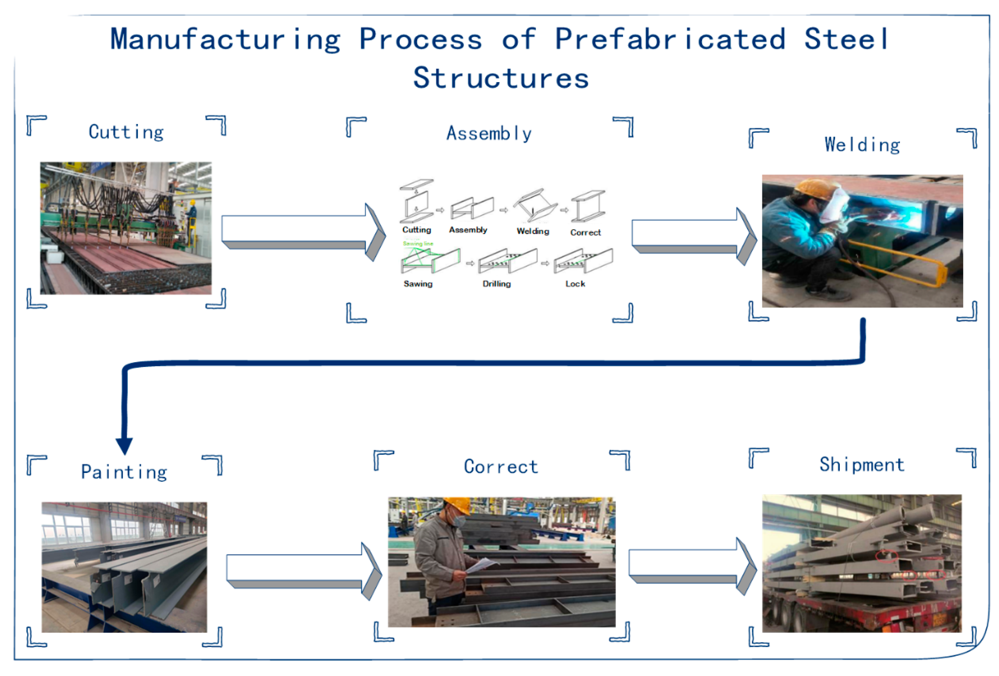
Figure 2 shows the main manufacturing processes of prefabricated steel structures, which are listed below, including (1) cutting: this is the beginning of all the manufacturing processes where the steel plates are cut into various shapes for the assembly of the components; (2) assembly: in this process, the accessory is assembled into components to be welded, and the various parts of the large components are assembled and formed on the flat ground; (3) welding: various methods of welding, such as gas shielded welding and wire electrode welding are used in the manufacturing of steel components; (4) painting: a dense and thin protective layer is formed on the component surface, which leads to the enhancement of corrosion resistance; besides, the quick response (QR) codes used to track the manufacturing process are attached in this process; (5) correct: if the deformation caused by welding is inevitable or the deformation exceeds specification requirements, the components need to be corrected to fulfill the specification requirements; and (6) shipment: once fulfilling the specification requirement, the components are shipped to the construction site, which means the end of the manufacturing process.
3.2. Platform Requirement
By preliminary interviews with frontline workers and managers, the central functional modules of this platform are concluded.
3.2.1. Non-Functional Requirement
The non-functional requirements of this platform are listed in
Table 1.
- (1)
Web-based
For the compatibility between different operating systems, the BIM platform should be web-based. In this way, users do not need to install any software and can access the platform with any devices only if there is a browser inside it. Moreover, once the developer updates the code on the server, all users can get the latest feature updates.
- (2)
Worksharing
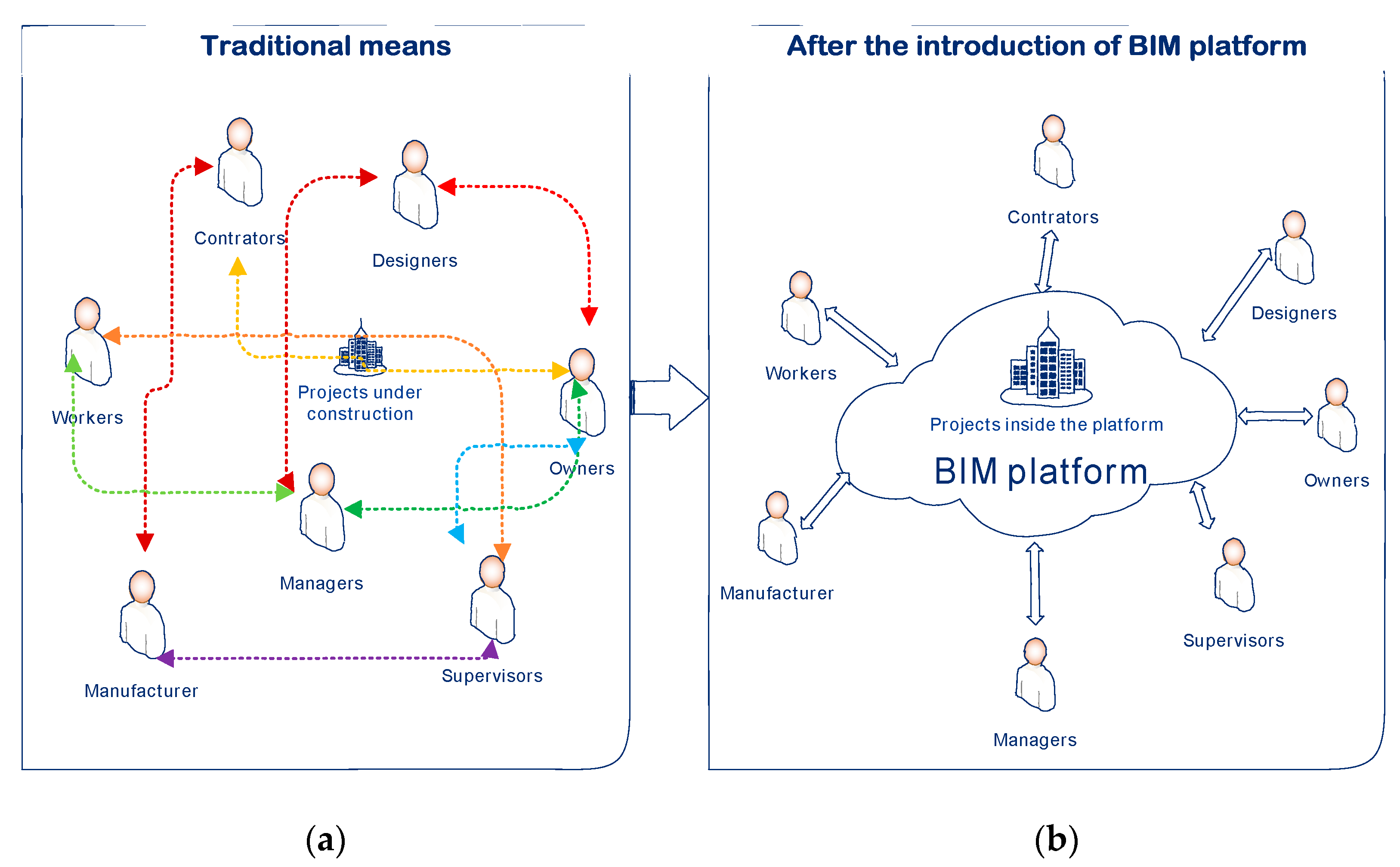
With different stakeholders involved in the same project, information exchange may be repetitive, complicated, and can sometimes even cause information loss and errors in traditional ways, as is shown in
Figure 3a. Megaprojects are more challenging to manage in terms of decreasing costs and increasing quality and productivity. Innovative approaches have been proposed to overcome the various challenges that the AEC area tries to address. A more collaborative and integrated project environment is essential in this process [
38].
After introducing the BIM platform, information exchange mainly operates on the platform, accessed by different stakeholders, as is shown in
Figure 3b. All the users participate in the manufacture through the same platform, which helps reduce the loss and mistakes arising during data exchange and promote the flow of manufacturing information.
This platform is multifunctional. Different stakeholders involved in the same project may access on the platform. However, each user has a different authority for a variety of modules. Besides, the safety of manufacturing data should be highly emphasized. Therefore, an authority management module is needed.
- (3)
Lightweight model
A web-based platform needs a lightweight model to improve loading efficiency. The characteristics of construction and management of steel structural buildings show that the degree of industrialization of them is relatively high. Many standardized components have the same geometric shape. Therefore, when software platform processing geometric files, these same geometric expressions will form redundant geometric information. If this redundant information is not processed in a targeted manner, the server-side will have problems such as large space occupied by geometric files, slow network transmission, and broad network bandwidth. When rendering on the client-side, problems such as high memory usage and heavy CPU load will occur. Therefore, based on the characteristics of the steel structure, this platform should deal with redundant geometric information. In the geometric information extraction and rendering stages, different components sharing the same geometric information should be left to improve the performance of the platform.
- (4)
Interoperability
Given that the models are usually built by other software, interoperability problems may trigger issues between stakeholders while performing the most significant tasks in the AEC industry. It is well known that these problems cause loss of money, time, and work hours for stakeholders who are involved in the design, planning, and construction phases [
14].
In the developed platform, the BIM models are exported by Tekla software in IFC format, with which the platform needs to interoperate with. Therefore, having a secure and verified internal configuration for a neutral file format like the one in IFC would be another critical point for the level of interoperability.
- (5)
User interface (UI) requirement
The design of the human–computer interaction interface should be clear, smooth and modern, with comfortable colors as well. Moreover, it needs to be compatible with operating systems such as IOS, Android, and Windows on common browsers (e.g., Safari, Chrome, and Firefox).
3.2.2. Functional Requirement
After visiting the manufacturing factory and discussing with frontline workers and managers, the functional and user interface requirements were concluded by analyzing the manufacturing processes. Besides, the manufacturer also supplements many new requirements based on actual production experience during the developing phase to make the platform match the actual manufacturing process. In general, the BIM platform should display real-time information for four phases, including the detailed design phase, manufacturing phase, finished product storage phase, and delivery phase through the model. Finally, users also need to query the detailed information of each component.
The platform should provide seven major functions: (1) fundamental function, including: registration and login, user role management, personal information maintenance, and the realization of standard social functions; (2) design management module; (3) process management; (4) detailed design; (5) project plan; (6) production management; (7) workshop management. The goal and descriptions of each module are listed in
Table 2.
3.3. Function Design
Having summarized the requirements, the design ideas of each functional module are described below. The subsequent development of this platform is based on these ideas.
3.3.1. Fundamental Functions
- (1)
Homepage
This page is used to display critical data for each project when running the platform, general information about each project, such as the main contractor, the degree of completion of each production batch, manufacturing progress in the time scale, is displayed here.
- (2)
Data statistic
A variety of manufacturing data need to be counted, such as the manufacturing quantity of each workshop. In addition, the statistics table can be exported in the form of Excel. By writing the query command for Neo4j, data can be transferred to the client-side. Then, by employing the functions of JavaScript, an Excel of the statistical data can be exported.
- (3)
Lightweight model
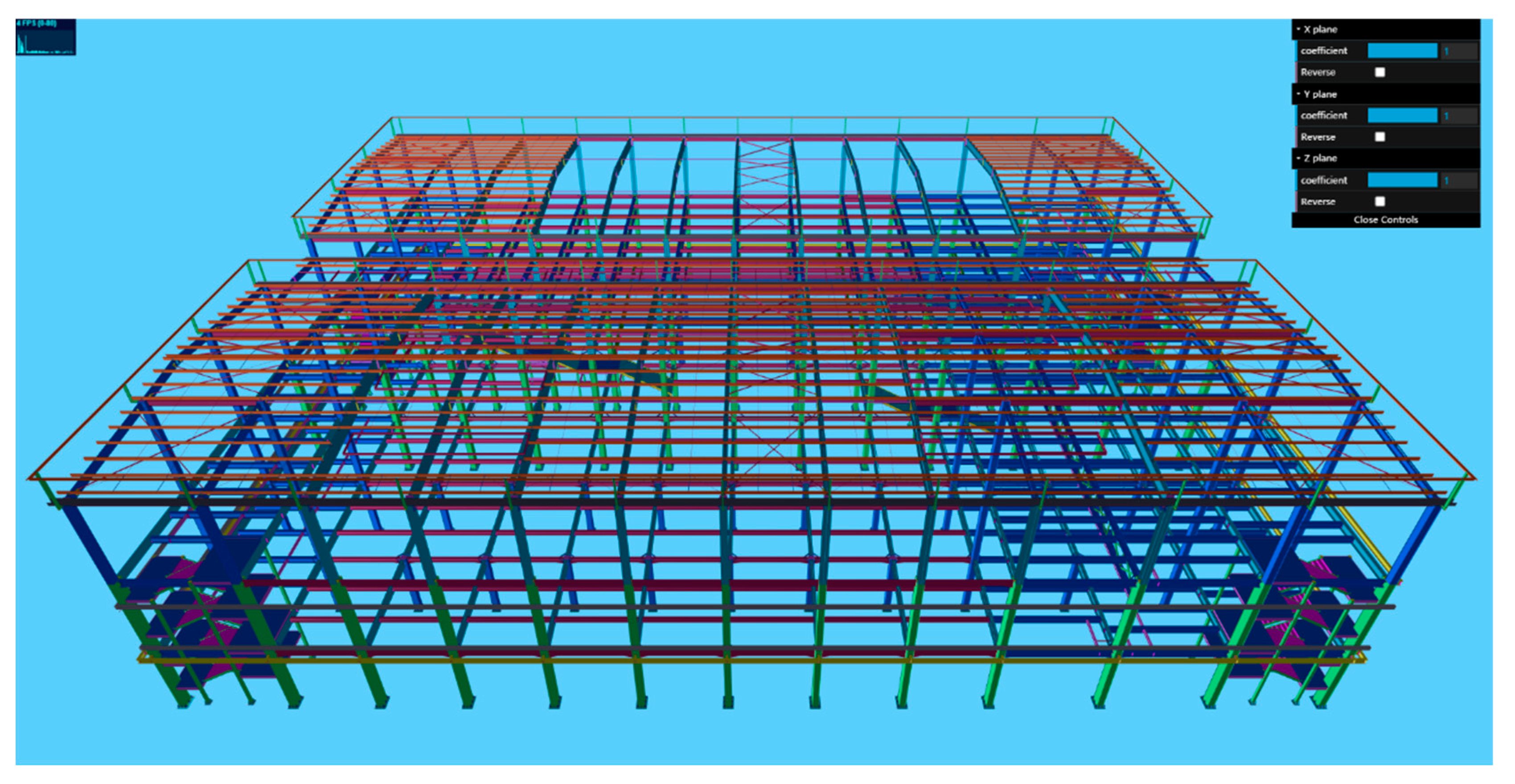
Three methods are presented for the lightweight model: (1) removing redundant geometric information of components. (2) Level of detail (LOD) model optimization: by using the triangular mesh simplification algorithm based on folding edges, the processing program for IFC file geometry information is developed. This program simplifies the mesh of the BIM model by reducing geometric complexity and dynamically loading models of different simplification levels on the display layer to optimize the rendering effect. (3) Static cache: the adoption of cache can reduce the loading time of BIM model and save network transmission bandwidth. Once the model is loaded, it will be automatically cached.
Figure 4 shows the lightweight processed model in the platform.
3.3.2. Project Creation
IFC is a standardized, digital description of the built environment, including buildings and civil infrastructure. It is an open, international standard (ISO 16739-1:2018), meant to be vendor-neutral, or agnostic, and usable across a wide range of hardware devices, software platforms, and interfaces for many different use cases [
39]. Therefore, the IFC format model can interoperate with various software programs.
In the developed platform, the plugin IfcConvert is used to convert the IFC format into OBJ format and XML format.
- (1)
Geometric information
On the one hand, the BIM model is converted from OBJ format into gLTF format, which is a 3D file format that can reduce redundant data irrelevant to rendering in the 3D format and is more suitable for OpenGL cluster loading using the JSON standard.
- (2)
Semantic information
On the other hand, the IFC format file is transferred to XML format by IfcOpenShell to extract semantic information of the components. Component information, such as globally unique identifier (GUID), weight, size, and position, is saved into MongoDB and Neo4j database.
In the XML format file, some spatial relations of the instance are shown as the inclusion relations of nodes. For instance, the inclusion relationship between IfcElementAssembly class and IfcBeam class is IfcRelAggregates.
The platform employs the plugin IfcOpenShell to convert the obtained XML format into JSON format that is convenient for Node.js operations. The plugin then performs depth-first traversal decoupling. Then, it saves the inclusion relationship of instances and the reference relationship between instances and attribute sets. Finally, these data are all stored in the database.
- (3)
Database storage
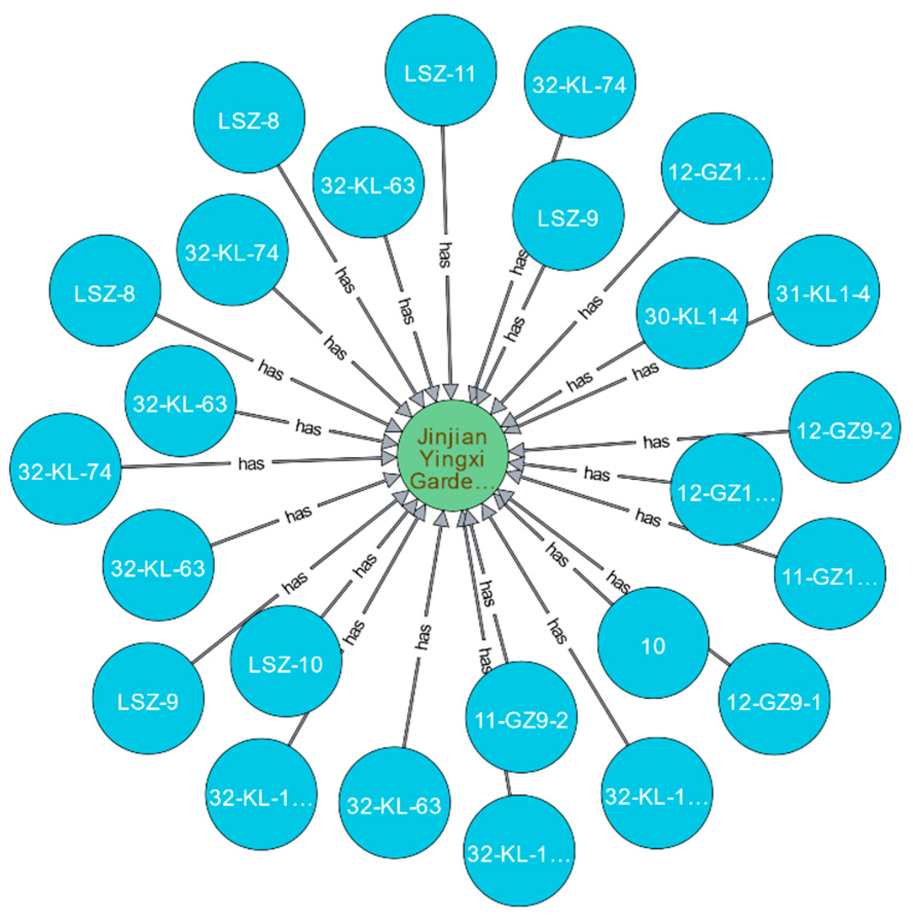
The graph database, Neo4j, is used for the storage of information. It is a type of NoSQL (not only structured query language) database and addresses the limitations of relational databases. In Neo4j, everything is stored in the form of an edge, node, or attribute. Each node and edge can have any number of attributes. Both nodes and edges can be labeled [
40]. Labels can be used to narrow searches. In conclusion, Neo4j is exceptionally suitable for the case where one project is linked with various nodes, such as components and drawing files. The storage structure of nodes in Neo4j is shown in
Figure 5.
3.3.3. Detailed Design
In this module, the component information, such as the weight, size, GUID, that was extracted from the IFC file is displayed. Moreover, the drawings file can be attached to the corresponding component. The component information also can be edited by users with specific authority.
3.3.4. Design Management
Files such as drawings can be uploaded and downloaded in this module. This module categorizes the drawing file according to the project and specialty, such as structure, construction, and heating, ventilation, and air conditioning (HVAC), to which it belongs. Meanwhile, considering that there will be multiple versions of drawing files, this module needs to manage different versions of drawing files.
3.3.5. Project Plan
Before the manufacture, users can arrange the manufacturing activity using the Gantt chart to visualize the progress. The schedule of each manufacturing process, and the manufacturing quantity and completion, are shown in this module. This module uses a tree table to display the data in the developed platform.
3.3.6. Production Management
In this module, users need to select components for manufacturing and a corresponding process plan to specify the manufacturing flow. Then, manufacturing progress is displayed in the module of progress management and component trace. In conclusion, this is the beginning of the manufacturing progress of this platform.
3.3.7. Progress Management
End-users can interact with the 3D BIM models in this module to visualize the manufacturing state of each component by displaying the processing progress on the model. Moreover, by clicking the component on the model, the detailed information of the component needs to be displayed.
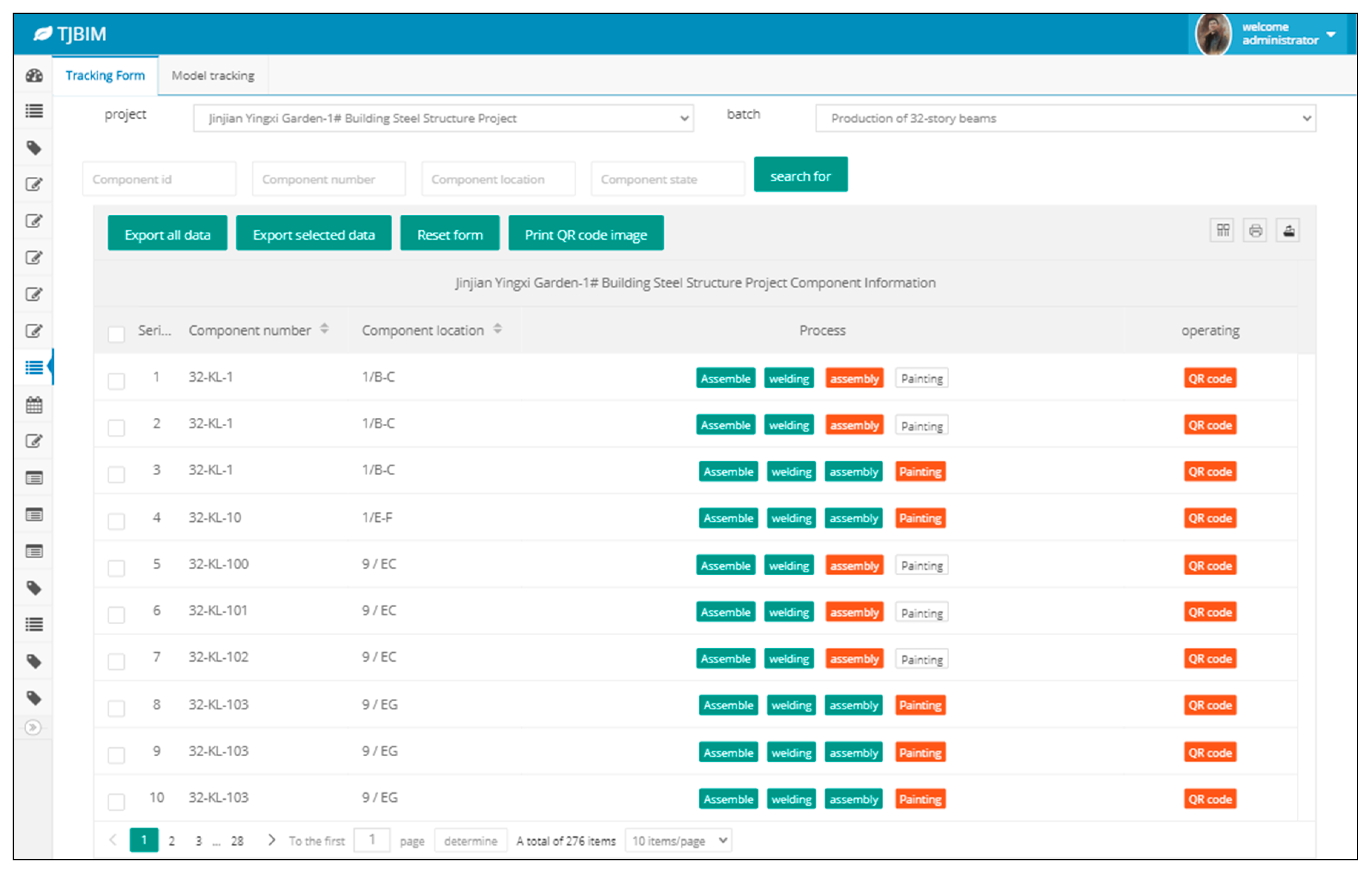
3.3.8. Component Trace
The actual process of each component in the manufacturing progress is displayed in this module where the different color indicates the different statuses of the manufacturing process. Moreover, the QR code, which is printed on the actual component, is generated in this module. By scanning the QR code, end-users can record whether the component fulfills the requirement of the ongoing process. Once it fulfills the requirement, the component will enter the next process.
3.4. Overall Architecture Design
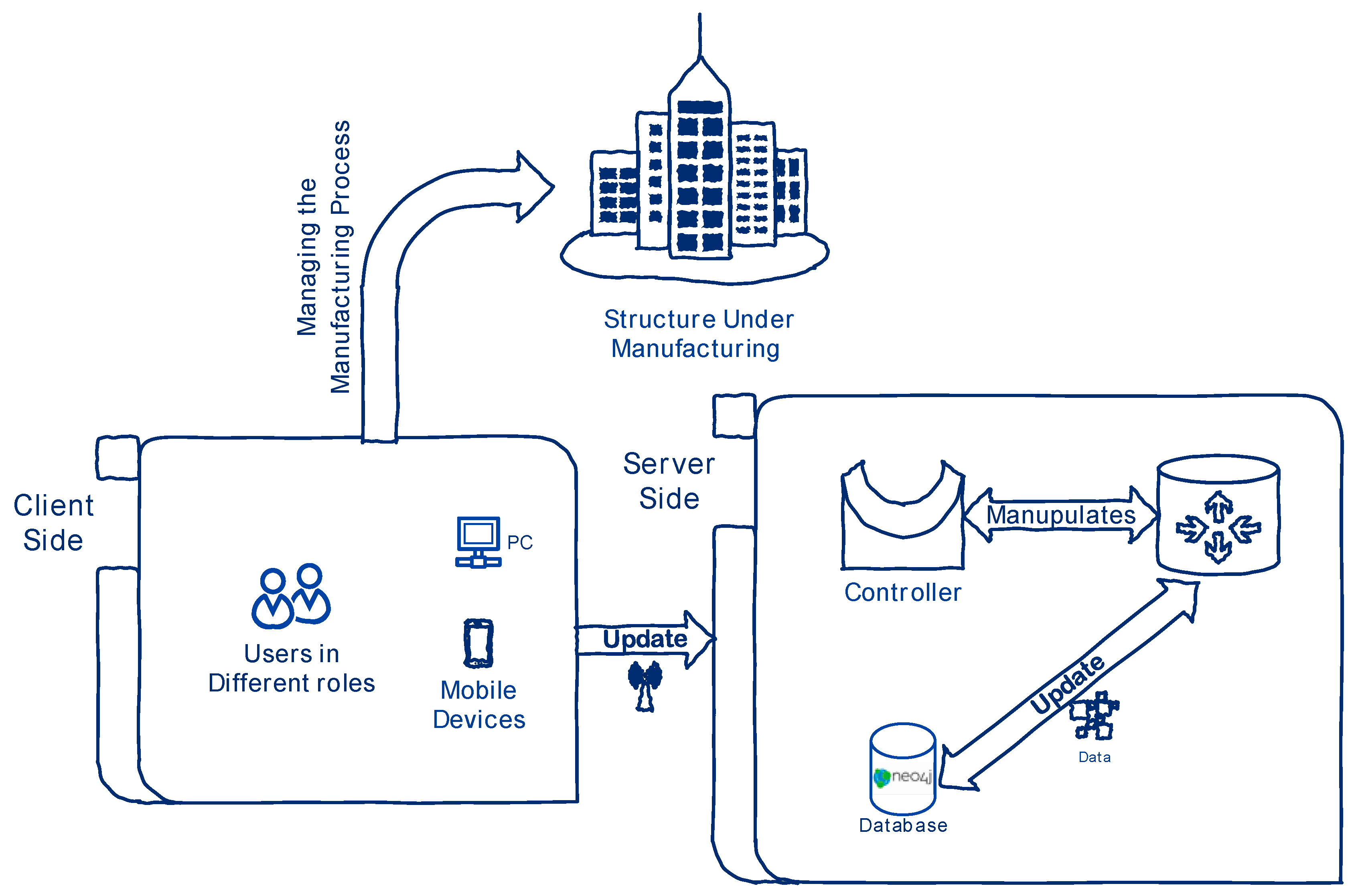
Figure 6 shows the architecture of the platform. As shown in this figure, the platform, which is based on an architectural pattern called MVC framework, separates an application into three main logical components: the model, the view, and the controller. Each of these components is built to handle specific development aspects of an application. MVC is one of the most frequently used industry-standard web development frameworks to create scalable and extensible projects [
41]. For the server part, Node.js is employed for command-line writing and server-side scripting. Subsequently, dynamic web page content is produced by running scripts on the server-side before the page is sent to the user’s web browser. The BIM server can connect to the aforementioned various application modules, as well as accept and process various requests initiated by each participant to the BIM platform. Furthermore, it can also process BIM data, return data processing results, and be integrated into the platform layer of the BIM platform architecture.
3.4.1. Model
The Model component corresponds to all the data-related logic that the user works with. This part can represent either the data transferred between the view and controller components or any other business logic-related data. For example, a customer object will retrieve the customer information from the database, manipulate it, and update its data back to the database or use it to render data. In this platform, the component part is responsible for establishing a data model and interacting with databases and C++ programs.
3.4.2. View
The view is the user interface of the platform. In other words, end-users can interact with the data in this interface. All the commands created by users is input in the view component and then transferred to the controller. In this platform, HTML (hyper text markup language), JavaScript, and CSS (cascading style sheets) are employed to design the interface.
3.4.3. Controller
The controller acts as an bridge between model and view components to process all the task logic and incoming requests, manipulate data using the model component, and interact with the views to render the final output [
42]. For instance, the controller will handle all the requests from view, such as query about component information and handle the request from the model. In other words, it acts as a bridge between the view and model.
4. Practical Application of the Platform
In this section, the actual application of the developed BIM platform is illustrated by taking the actual projects as examples. Google Translate is adopted in several pages to translate Chinese into English.
4.1. The Main Page
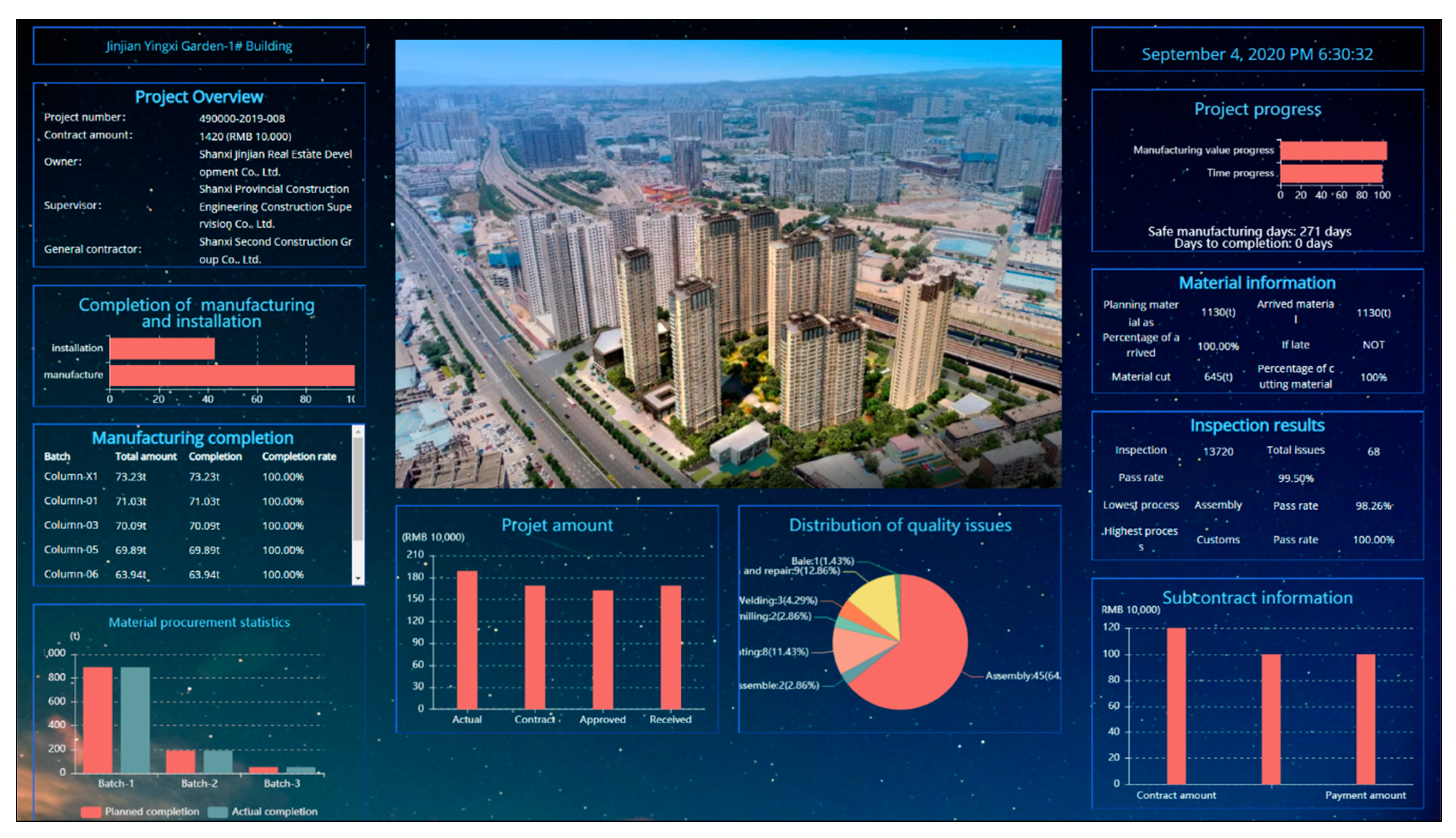
As shown in
Figure 7, the main page is the first page that comes into the users’ sight. General information, such as the owner, supervisor, and constructor, is displayed in this interface, and its primary function is to help users have an initial understanding of all projects. The platform automatically counts the completion ratio of each manufacturing batch and the distribution of quality problems in different processes, which are shown as pie charts or histograms. Besides, the completion of manufacturing and installation, material procurement statistics, project amount, material information, inspection results, and subcontract information are also shown on this page.
4.2. Creating Project
The IFC format model exported by Tekla software can be uploaded on the platform. Meanwhile, some vital information of the project, such as project name, project number, owner, supervisor, and constructor, can be input by the users. Once uploaded, the platform will parse the IFC file automatically and insert the information into the Neo4j database, which is the base of all the following interoperation. The following sections will take the manufacturing process of an actual project as an example.
4.3. Detailed Design
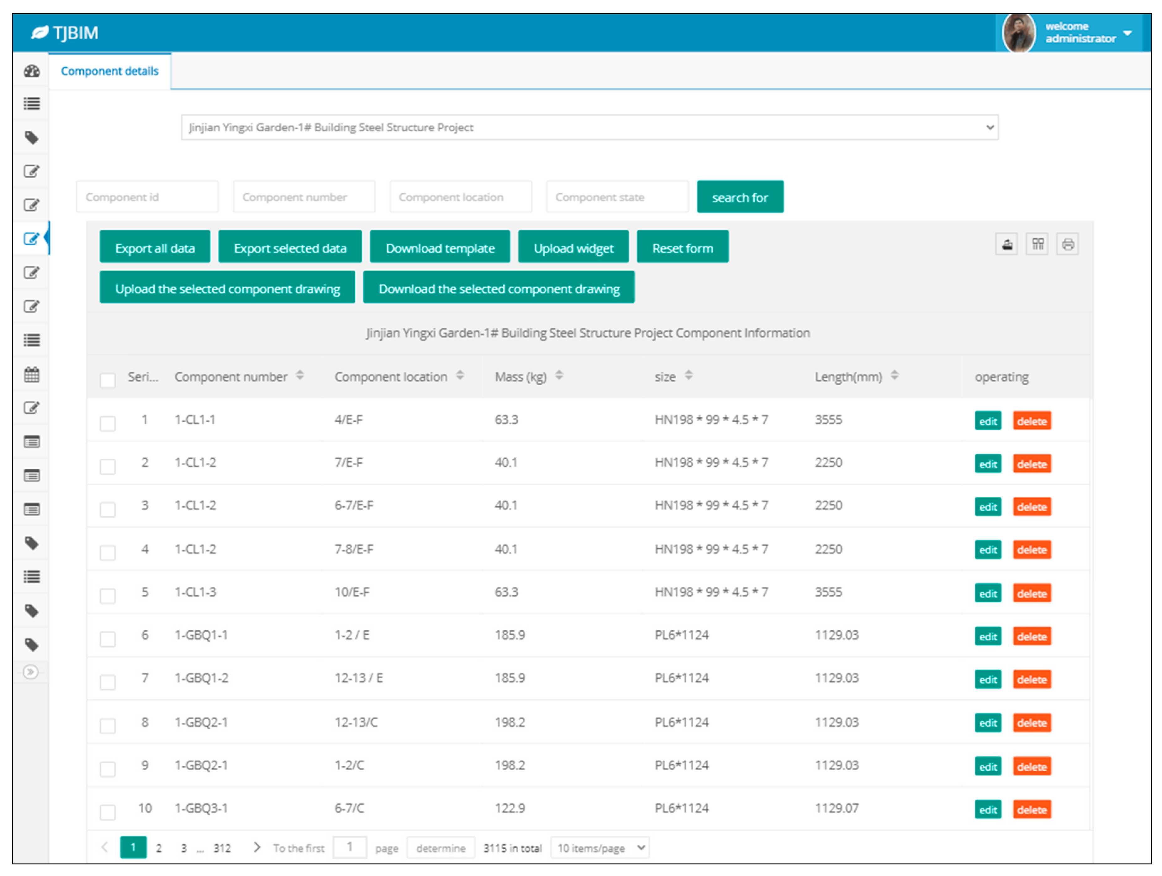
After parsing, the XML file is converted from the IFC file, in which component information, such as ID, tag, weight, size, and length, exists in the form of IfcPropertySet class and IfcElementAssembly class in the XML file. Furthermore, the detailed design information is displayed in this module, forming the basis of the data for the subsequent steps, as shown in
Figure 8. Due to the actual complex and variable conditions of the projects, this module provides the modification function of component information, which is available for specific users who have the authority.
4.4. Production Management
Firstly, users need to select the components to be manufactured so as to form a batch. Then, users need to select the specific process plan for the batch. This procedure determines the following manufacturing process of this batch and implements essential information such as manufacturing workshop and group, foreman for each process. After that, the manufacturing processes start and are traced in this platform.
4.5. Component Trace
This function captures the real-time data of the prefabricated steel manufacture in the factory to allow meaningful and useful information to be extracted. Once the production plan is made, the manufacturing processes can be tracked. As shown in the column named “Process” in
Figure 9, each color indicates the different statuses of the manufacturing process, where green indicates that the process is completed, white indicates that the process has not started, orange indicates that the process is delayed. As shown in
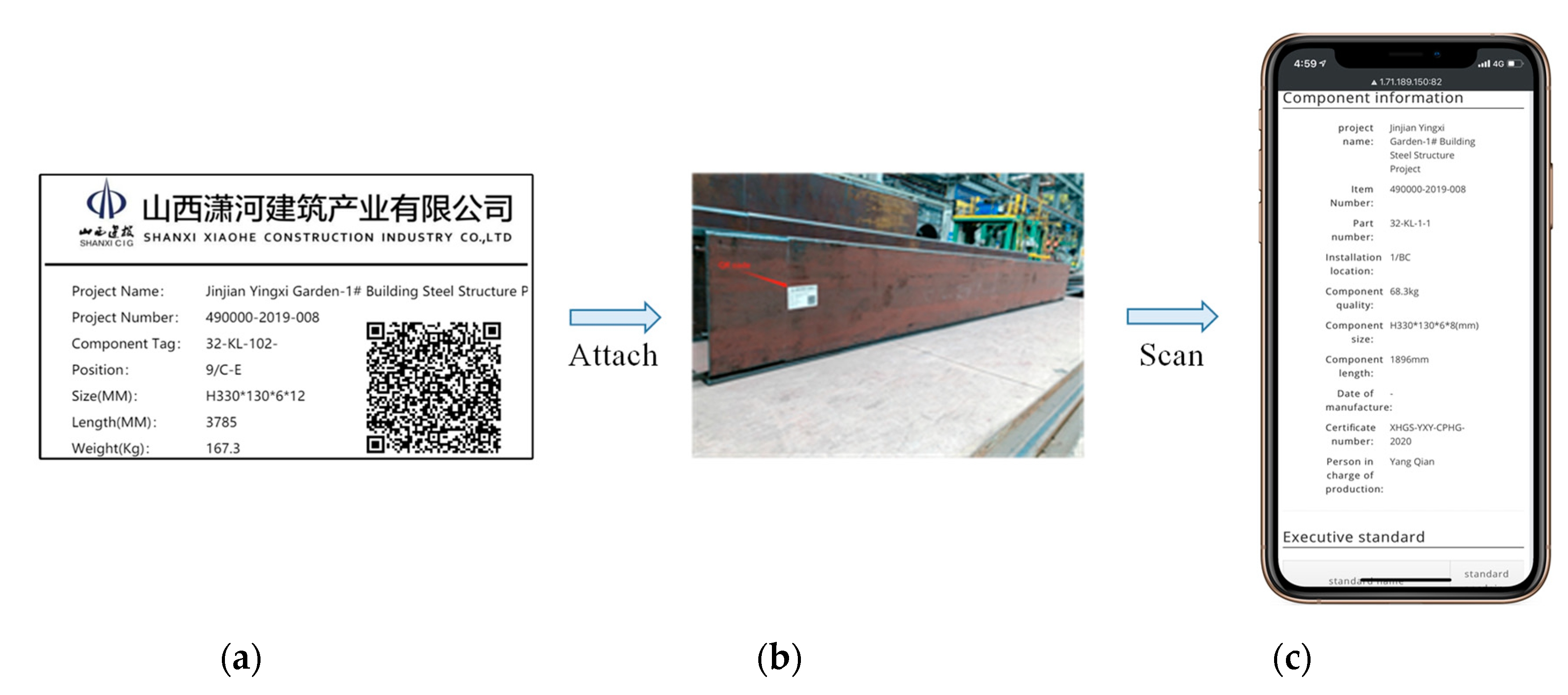
Figure 10, by scanning the QR code attached to the component by a mobile device, the on-site workers can get access to the mobile web page and record the quality inspection results. Once qualified, the component will flow to the next process. Whereas if the quality inspection failed, it will remain in the same process until qualified. Real-time data are then transferred to the server to facilitate enhancing the traceability of manufacturing progress and resolving the quality problems, such as quality defect, manufacturing delay delivery, and assembly interruption. Moreover, this function can also facilitate and coordinate various stakeholders by supporting their decision-making.
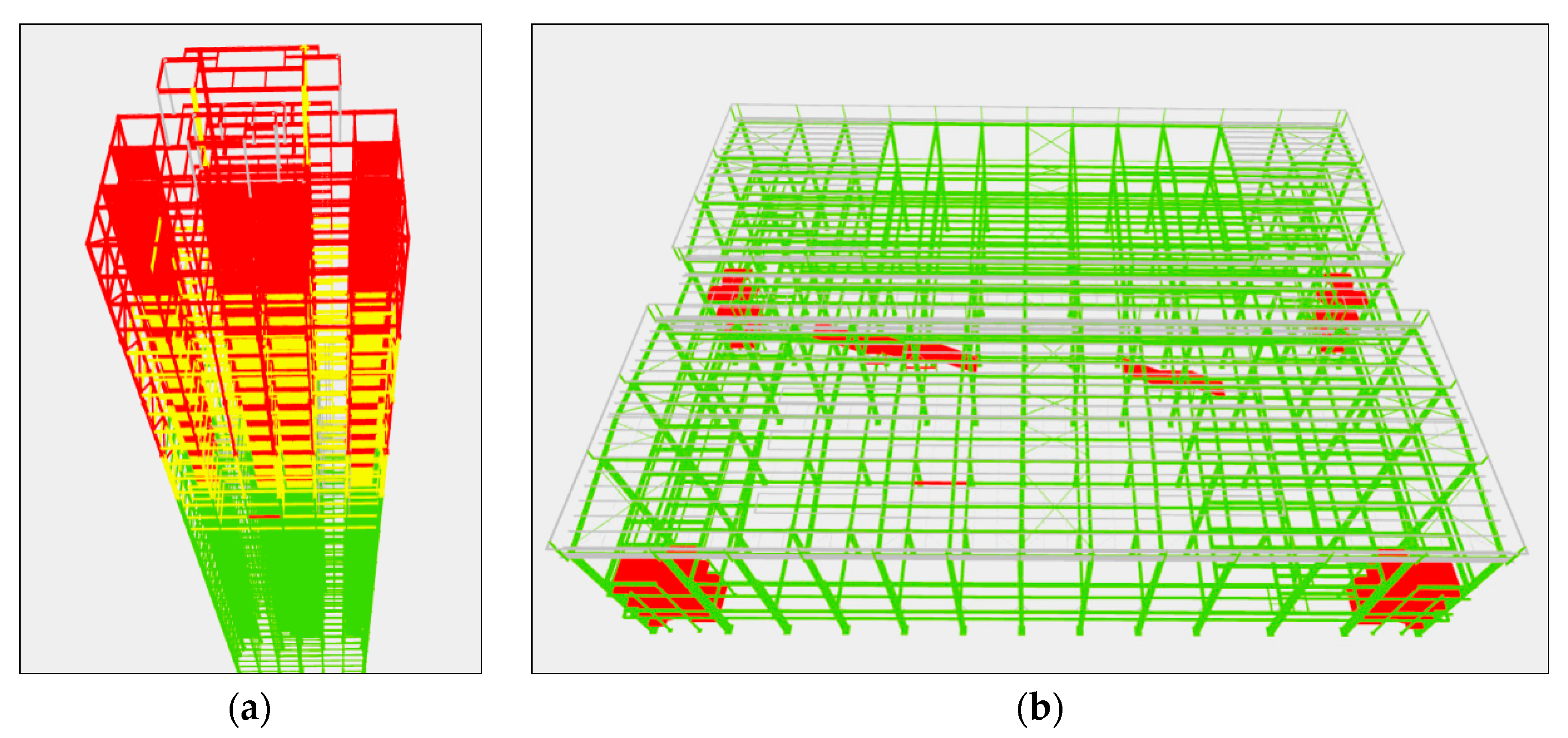
4.6. Progress Management
This module visualizes the real-time manufacturing progress of each project using the imported BIM model so that users can grasp the progress at just a glimpse. As shown in
Figure 11a, this project is a multi-story prefabricated steel structure. Components in different statuses, such as under waiting for manufacture, manufacturing, or storing in the warehouse, and shipped, are displayed in different colors. This module visualizes the manufacturing progress in the overall scale of the project.
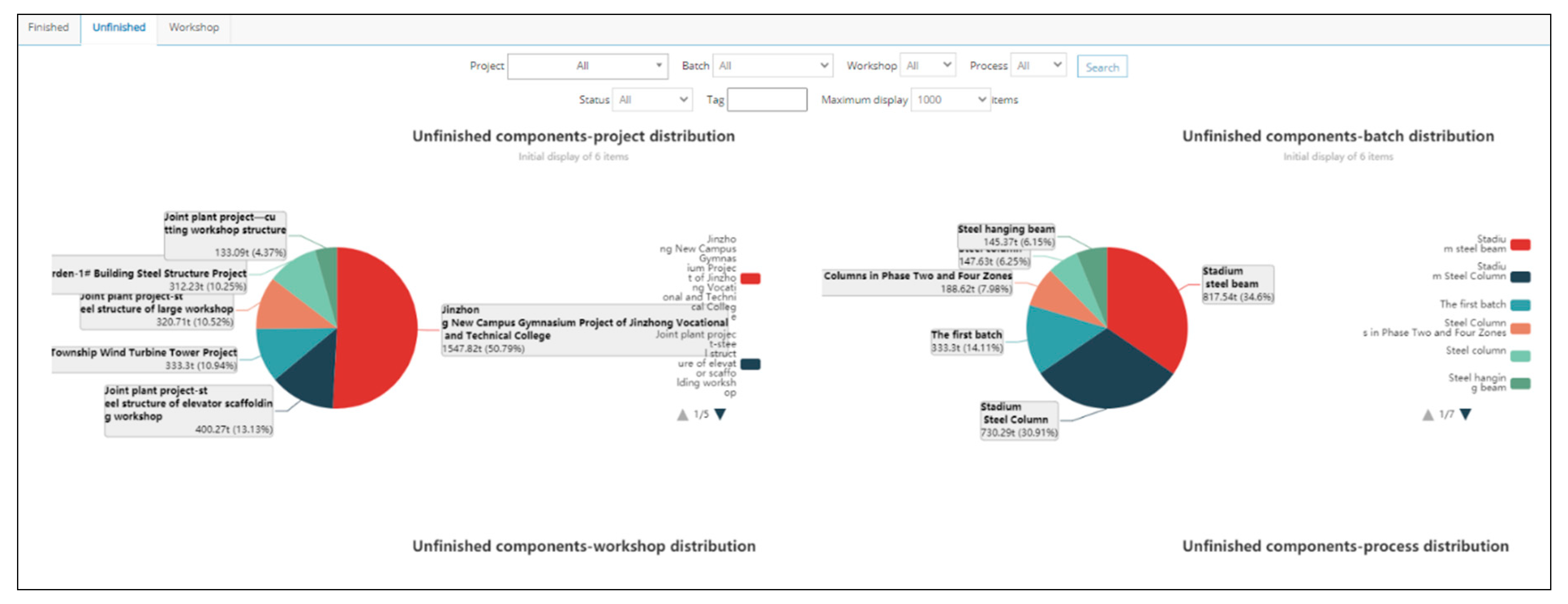
4.7. Fundamental Functions
Registration: On-site workers can register with different roles, after which different roles have different permissions for functions.
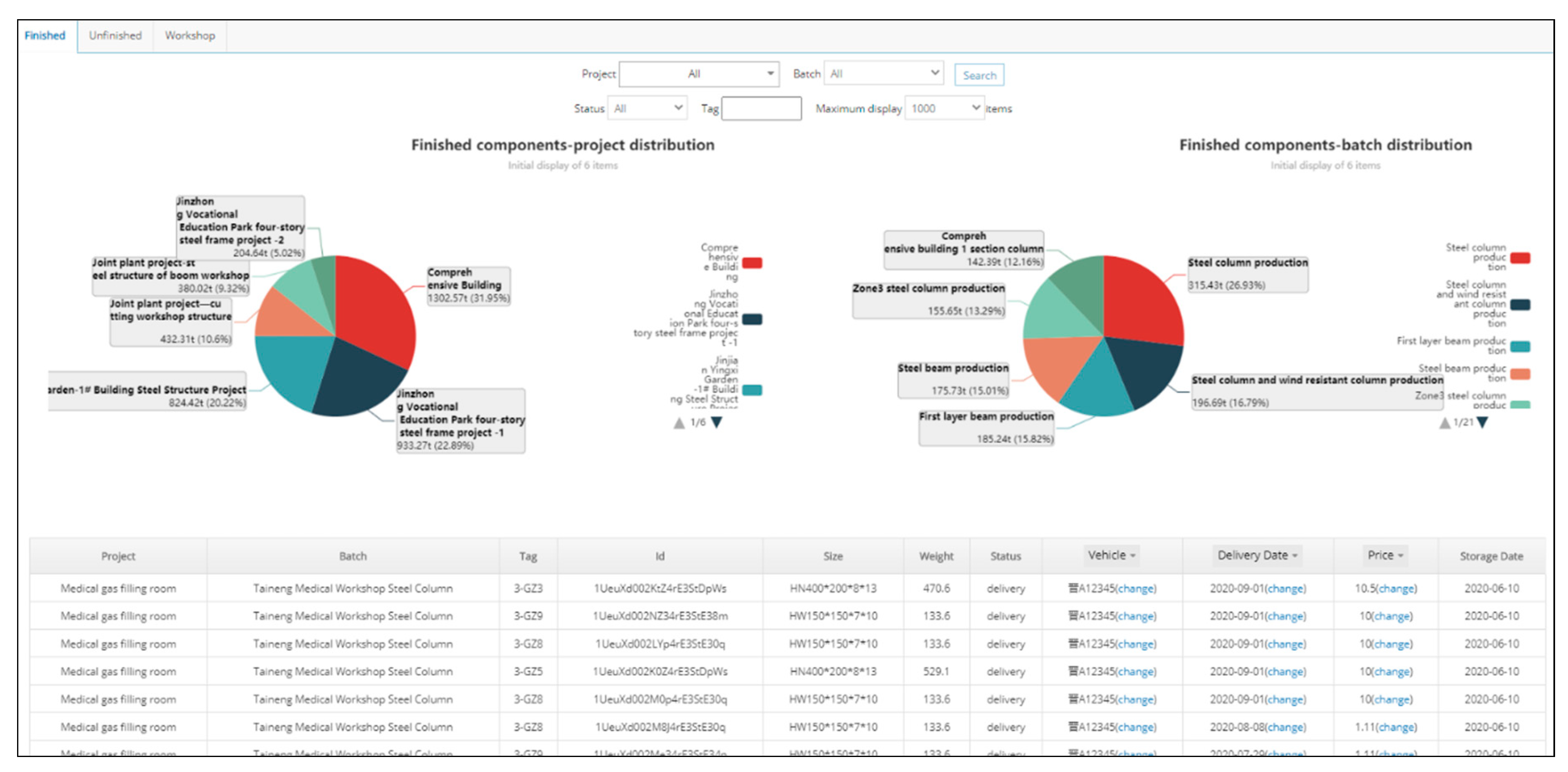
Data statistics: Production data are counted to provide users with another perspective on progress, including the production quantity of each workshop, the quantity of components that have been manufactured and stored in the warehouse of each project, as well the quantity of components that are manufacturing. The interfaces of the data statistics are shown in
Figure 12 and
Figure 13.
Authority management: By providing users with different roles with access to different functions, this function improves production data security and facilitates participation in the flow of manufacturing information of users in various roles.
4.8. Results of Practical Application
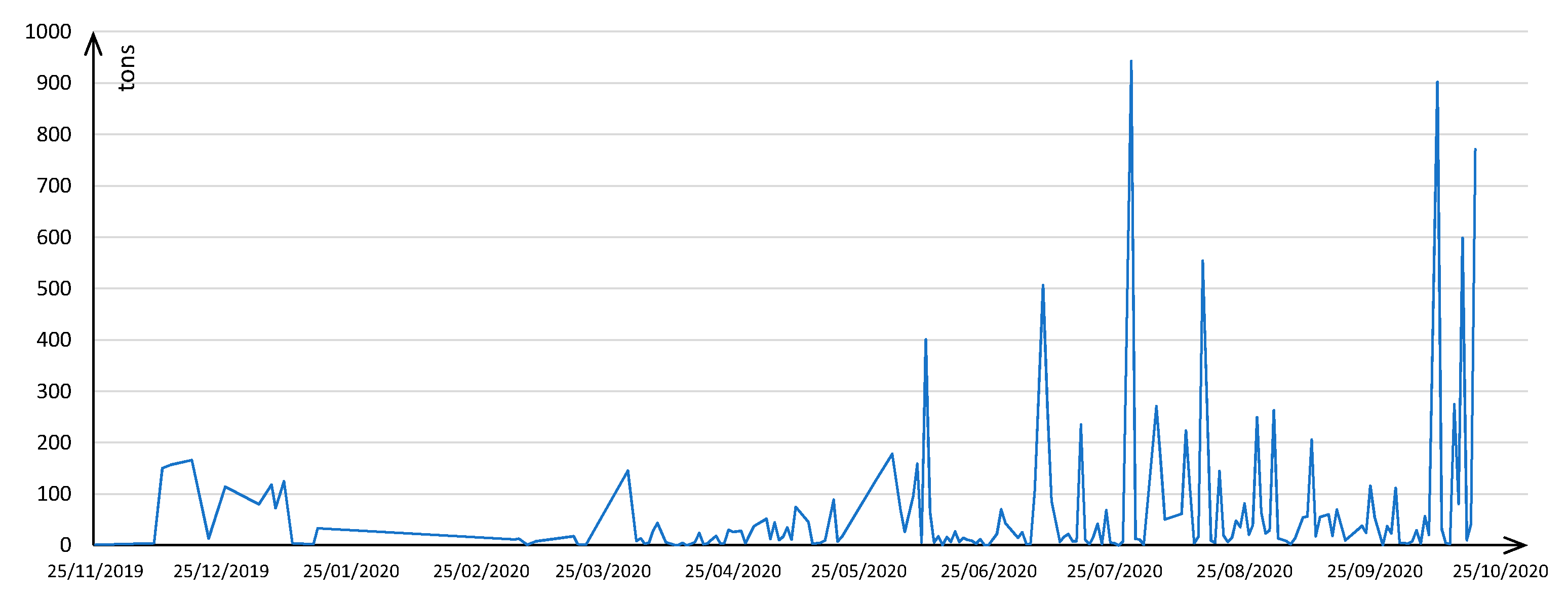
As of 19 October 2020, the BIM platform has been applied to 43 projects which are manufactured or under manufacturing, and the total steel weight is 25,036 tons. As depicted in
Figure 14, after introducing the BIM platform on 25 November 2019, the steel components’ production traced in the platform fluctuated around 100 tons per day at the initial stage and increased significantly to several hundred tons per day after half a year around. In other words, the platform is participating in more and more manufacturing activities in the factory, which indicates that it has been accepted by more and more users, such as workers and managers.
5. Conclusions and Future Work
In this article, a BIM platform for the manufacture of a prefabricated steel structure is developed and applied in some actual projects. The platform acted as the “brain” of intelligent production management in the centralized control center of the manufacturing factory. It achieved the information-based whole-process management of steel structure processing and manufacturing, and the traceability of components by QR codes. During manufacturing, it acts as a bridge that communicates with all involved parties, making essential information accessible to corresponding users. Base on the developed platform, the quality of steel components and manufacturing efficiency has been dramatically improved.
Firstly, this article summarized the technical characteristics and application directions of BIM and the development trend of prefabricated buildings in China. Then, it summarized the critical problems in the management of the manufacturing process of prefabricated steel structure buildings and proposed feasible solutions to the problems, and finally developed a BIM platform for the manufacturing management of the assembled steel structural building. This platform combines with WebGL, IoT, and BIM technology, and realizes the functions of IFC file parsing, data analysis and storage, model visualization and interaction, component production process management, and other functions. The platform takes the separated projects as the management unit and the components as the management objects. Additionally, it realizes the tracking of components in the whole manufacturing process. By assigning different permissions to each user role, a clear division of labor is presented. Thus, the efficient collaboration of the manufacturing management platform is realized. In conclusion, this platform not only helps frontline workers and inspectors to conveniently query and input the information of components but also facilitates the macro-control of the overall progress of managers. Besides, it also has made full use of the synergy and highly visible characteristics of BIM technology to realize the adequate management of the whole progress of the manufacture of steel structure.
The platform can effectively improve the degree of informatization in the component manufacturing progress, which is convenient for managers and workers to grasp the manufacturing progress in real-time, and to solve the production problems such as delivery delay and quality defects in a timely manner. Finally, through the case study of the actual application, the practicability of the platform was confirmed. Therefore, the developed platform can work as a collaborative tool in the manufacturing processes among different users.
However, limitations should be put forward for its further improvement and broader application. This platform only aims at the manufacture of steel structures, which is the initial phase of the life cycle of the buildings. Therefore, a BIM platform for the full life cycle of buildings needs to be further developed. The recognition of components is limited to the QR code attached to it. The application of the other IoT technology, such as RFID technology, can be further employed to increase the recognition efficiency of components. Besides, the performance limitations on the web side require a higher-level lightweight model. Finally, interoperability between other mainstream BIM software such as Revit and Bentley should be further developed for the broader adoption of this platform.


