Article

Long-Term Deflection of Prestressed Concrete Bridge Considering Nonuniform Shrinkage and Crack Propagation by Equivalent Load Approach

1
Department of Transportation System Engineering, KRRI School, University of Science & Technology, 217, Gajeong-ro, Yuseong-gu, Daejeon 34113, Korea
2
Korea Railroad Research Institute, 176, Cheoldo-bangmulgwan-ro, Uiwang, Gyeonggi-do 16105, Korea
3
Department of Transportation System Engineering, Graduate School of Transportation, Korea National University of Transportation, 157, Cheoldo-bangmulgwan-ro, Uiwang, Gyeonggi-do 16106, Korea
*
Author to whom correspondence should be addressed.
Appl. Sci. 2020, 10(21), 7754; https://doi.org/10.3390/app10217754
Submission received: 23 September 2020 / Revised: 27 October 2020 / Accepted: 29 October 2020 / Published: 2 November 2020
(This article belongs to the Special Issue Advances on Structural Engineering, Volume II)

Abstract

:

Featured Application

Design of Prestressed Concrete Bridges.

Abstract

Long-span prestressed concrete (PSC) bridges often suffer excessive deflection during their service lives. The nonuniform shrinkage strains of concrete caused by uneven moisture distributions can induce significant additional deflections, when combined with the creep and cracking of the concrete. Current design practices usually overlook these factors, and the few proposed approaches to consider them are complex and computationally expensive. This study proposes a simplified approach for considering the effect of nonuniform shrinkage by using the equivalent load concept in combination with a nonlinear analysis of the creep and cracking using three-dimensional finite element models. The long-term deflections of short-, medium-, and long-span PSC bridges are calculated under the combined effects of creep, shrinkage, and cracking. The results show that the nonuniform shrinkage effect is significant in medium- to long-span bridges, and that the cracking of the concrete reduces the stiffness, thereby increasing the long-term deflection of the bridges (more severely so in combination with creep and shrinkage). The predicted long-term deflections reasonably agree with the measured data. Thus, the equivalent load approach is effective for calculating long-term deflections considering nonuniform shrinkage strains, without the complicated and expensive coupling of moisture transport and structural analyses.

1. Introduction

Modern transportation systems, such as high-speed train systems, demand for long-span bridges are increasing. The longer span length and faster operating speed make the system very sensitive to deflections of super and sub-structures [1]. Accordingly, accurate prediction of the time-dependent deflections of these structures (especially slender bridges) has become imperative.
Long-span prestressed concrete (PSC) bridges often suffer excessive deflections during their service lives. This excessive deflection is mainly owing to the creep and shrinkage of the concrete. Current design codes provide practical methods for predicting the long-term deflections of concrete bridges, but they often underestimate the results [2,3,4,5].
One cause of such underestimation is that the codes overlook the effects of the nonuniform shrinkage caused by an uneven moisture distribution along the section of the girder. The uniform shrinkage only induces an axial shortening, while the non-uniform shrinkage can induce a curvature. Thus, the nonuniform shrinkage strain can lead to significant additional deflections in PSC bridges [2,3,4], especially in large box girder bridges. However, in the design of a PSC bridge, the effects of nonuniform shrinkage are usually ignored. A number of studies have been attempted to investigate this nonuniform shrinkage with varying degrees of accuracy and complexity. Huang et al. [2] assessed the effects of nonuniform shrinkage independently from other creep-related analyses and verified that the thickness of a girder has a significant effect on the long-term deflection. Maekawa et al. [3] performed a parallel multi-scale thermo-hygral analysis that coupled moisture migration with the structural response to stress and strain. In their approach, the actual deflections of bridges were found to be between two analysis results performed while assuming extreme wet and dry exposure conditions. In addition, they pointed out that the distribution of the relative humidity (RH) within the cross-section affects the creep deformation until it reaches an equilibrium state with the external RH. The rate of drying might vary according to the size of the structure even if the geometric shape is the same, resulting in different rates of creep. Yu et al. [4] proposed an algorithm for a more realistic creep analysis with a rate type creep formulation based on a Kelvin chain model to capture the effects of humidity and temperature variations. They also considered changes in the degree of hydration according to humidity and temperature, bond–slip behaviors, and cyclic creep. Furthermore, Yu et al. [4] discussed that the estimation of long-term prestress loss is generally insufficient for creep-sensitive structures. As the prestress loss due to steel relaxation may significantly depend on the strain variation in concrete, it needs to be calculated as a part of structural analysis together with creep and shrinkage. They noted that current design practices significantly underestimate the effects of these factors on multi-decade creep in large-span PSC bridges.
In PSC bridges with partial prestressing, where tensile stress and cracking are allowed under service load, flexural cracking may be another reason for the errors in calculations of the deflection (in addition to the nonuniform shrinkage). Cracks cause stiffness degradations and promote deflection at the mid-span. The creep and shrinkage of the concrete will further increase the deflection and promote the propagation of cracks and the emergence of additional cracks [5]. Current design codes also provide a way to consider the effects of cracking, so called the effective moment of inertia approach [6,7]. This approach uses a reduced moment of inertia to calculate the deflection by ignoring regions subjected to higher stress than the modulus of rupture of the concrete after onset of cracking. That is, this approach considers cracking as a one-time event. However, actual cracking is a more rigorous and progressive phenomenon. It is a continuous process of softening, internal damage, and debonding, eventually leading to a geometrical discontinuity [8]. Hence, to correctly consider the effects of cracking, the material must be modeled in a way that describes the actual phenomena and that considers the contributions of the concrete between cracks to the overall stiffness of the member. This tensile action of the concrete between cracks is called tension stiffening [9]. According to Allam et al. [9], the tension stiffening effect can be reduced by creep and cyclic loading. American Concrete Institute (ACI) Committee 224R-01 [10] states that long-term or repetitive loading extends the magnitude of cracking by up to 200%. Although the coupled hygral and structural analysis approaches are more suitable for capturing the above-mentioned factors simultaneously, they are considerably complicated and computationally expensive. In addition, most commercial software is not capable of performing such an analysis; thus, one must develop a custom-made code adapted for that specific analysis.
In addition to the above-mentioned factors, discrepancies in design estimations of time-dependent deflections can arise from an oversimplified structural analysis model [4]. In the structural analysis of a design calculation, PSC girders are often simplified as one-dimensional (1D) beams. However, such a simplification cannot account for the differences in the drying rates of the slab and girder resulting from the different thicknesses of the members and environmental exposures, and/or the shear lag effect. The shear lag effect is a nonuniform stress distribution along the flanges of slender flexural members, such as box girders. The large shear force transferred from the vertical webs to the horizontal flanges of the box girder induces an in-plane shear deformation resulting in a higher longitudinal deflection at the flanges near the web [11]. In summary, the current design calculations significantly underestimate the long-term deflection, especially for large-span bridges built using a segmental construction method [2,9]. For a more realistic calculation of the long-term deflection, the PSC bridge superstructure should be analyzed using a three-dimensional (3D) model that considers the effects of non-uniform shrinkage and cracking, as well as creep and uniform shrinkage.
With this background, this study proposes a simplified approach for capturing the additional effects of nonuniform shrinkage in a 3D structural analysis simultaneously with those concrete creep, uniform shrinkage, and cracking models, based on commercial software. In this approach, the structural and moisture transport analyses are conducted using two 3D finite element (FE) models. The moisture transport analysis is performed independently from the structural analysis. The curvature owing to the nonuniform shrinkage is calculated from the moisture transport analysis, converted to an equivalent load at every time step, and applied to the nonlinear structural analysis model. In the nonlinear structural analysis, the combined effects of creep, uniform shrinkage, and cracking are analyzed by superimposing the equivalent load on other permanent loads such as the self-weight, prestressing force, and/or weight of the track or pavement.

2. Long-Term Deflection Calculation in Existing Design Codes

In current design practice, the elastic deflection of a concrete girder owing to various types of mechanical loads (such as self-weight, prestressing force, and other imposed loads) is calculated by considering the bridge superstructure as a 1D beam. Subsequently, the long-term deflection is calculated by multiplying the elastic deflection by coefficients representing the effects of creep and shrinkage, as suggested by design codes such as those from the American Association of State Highway and Transportation Officials (AASHTO) [7], ACI [10], Precast/Prestressed Concrete Institute (PCI) [12], International Federation for Structural Concrete [13], and Eurocode [14].
For example, per the multiplier method in the PCI bridge design manual [12], the elastic deflection owing to the self-weight ( δ s w ), prestressing force ( δ p i ), and other permanent loads in service ( δ s l ) is initially calculated using the following formula:
δ e =   K M L 2 E c I g
In the above, δ e is the maximum instantaneous elastic deflection along the beam, M is the applied moment (can be the result of either concentrated or distributed load), L is the length of a beam, E c   is the modulus of elasticity of the concrete, I g is the gross 2nd moment of the area, and K is a factor representing the support fixity and loading condition. Then, for a bridge with composite topping, the time-dependent deflections at important time stages are calculated as follows.
(i)
Net erection deflection before permanent service load ( δ n e )
δ n e   =   1.8   δ p i   +   1.85   δ s w
(ii)
Net final deflection without permanent service load ( δ n f )
δ n f   =   2.2   δ p i   + 2.4   δ s w
(iii)
Net final deflection with permanent service load ( δ n f s )
δ n f s   =   2.2   δ p i   + 2.4   δ s w +   3   δ s l
The multiplier coefficients in the above equations are determined by considering the creep and shrinkage of the concrete and may vary according to the creep and shrinkage models of the design code. Nevertheless, all the coefficients are calculated based on the same approach, i.e., a 1D simplification neglecting the nonuniform shrinkage effect.
Another example is fib Model Code 2010 (MC2010) [13], which recommends the following simplified equation to calculate the long-term deflection ( δ t )
δ t   = ( 1 + C c ) δ e
where δ e is instantaneous deflection and C c is the creep coefficient.
To account for the effects of cracking, the effective moment of inertia approach is common among design codes [6,7]. In this approach, the gross area moment of inertia ( I g ) is replaced with the effective area moment of inertia ( I e ), i.e., the average between the cracked and gross area moments of inertia upon the initiation of crack. However, the effective moment of inertia approach does not consider crack growth or the development of multiple cracks with creep.
In summary, as discussed in the introduction, the current design practice does not consider nonuniform shrinkage, progressive cracking, or the shear lag effect.

3. Modeling

3.1. Basic Concept of Modeling and Equivalent Load Approach

Two 3D FE models with user-defined materials were developed using “DIANA FEA” [15,16], a commercial multi-purpose structural analysis software. The first model, Model-1, was used for the moisture transport and nonuniform shrinkage analysis; the second model, Model-2, was used for the nonlinear structural analysis considering the creep, uniform shrinkage, and cracking.
Using Model-1, a transient moisture transport analysis was performed based on transient heat flow analysis, and the resulting deflections were obtained and converted to equivalent loads, which are defined herein as distributed loads for replicating the deflections induced by nonuniform shrinkage strains owing to an uneven distribution of moisture across the section. Then, the equivalent loads were used in conjunction with other permanent loads to perform a nonlinear time step structural analysis using Model-2. The nonlinear structural analysis using Model-2 simultaneously considered the creep, uniform shrinkage, and cracking to determine the long-term deflection of the beam.
The details are presented in the following subsections.

3.2. Moisture Transport Analysis

The migration of moisture from a higher concentration zone to a lower concentration zone can be described using Fick’s law of diffusion [2,17,18]. The equation for moisture transport can be written in a matrix form, analogous to the heat balance equation, as follows [2,17,19].
[ I ] d h d t + [ D ] h = F
Here, [I] is the identity matrix, F is the net moisture load vector (evaporation), h is the nodal RH vector, and [D] is the moisture diffusion coefficient matrix. The moisture diffusion coefficient of the concrete can be calculated using Equation (7), according to the fib MC2010 [13]. It should be noted that self-desiccation was not considered in this analysis.
D ( h ) = D 1 [ α + ( 1 α ) 1 + ( 1 h 1 h c ) n ]
In the above, D 1 represents the diffusion coefficient when h = 1.0, α is a parameter representing the ratio D 0 / D 1 , D 0 is the lower limit of the diffusion coefficient for h = 0.0, D 1 = D 1 , 0 / f c k (where f c k is the characteristic compressive strength of the concrete (MPa) and D 1 , 0 = 1 × 10⁻⁸ (m2/s)), h c denotes the RH at D ( h )   =   0.5 D 1 , and n is an empirical constant. According to MC2010 [13], it is assumed that α = 0.05, h c = 0.8, and n = 15.
Drying shrinkage is proportional to the loss of water in concrete, and thus, the following relation has been suggested [18]:
ε N U S   =   β s h ( 1 Δ h )
Here, ε N U S is the nonuniform shrinkage strain, Δ h is the difference in the RH, and β s h is a hydro-shrinkage constant. It is suggested in the literature that β s h lies in the range of 1 × 10⁻³–3 × 10⁻³ [2,20,21]. Alvarado [22] used fitting to shrinkage test data to show that β s h increases with an increase in RH in the RH range of 30 to 90%. In addition, β s h can drop below 1 × 10⁻³ for RH values of 60% or lower.
DIANA FEA [15,16] provides the general potential flow analysis, in which the potential flow is driven by the potential (temperature or concentration) gradient, as follows:
q   =   k φ
Here, φ is the potential gradient, q is the specific flux vector, and k is the conductivity or diffusivity. Accordingly, a moisture transport analysis can be performed as a transient heat flow analysis by replacing the temperature and heat flow with the humidity and moisture flow, respectively. Then, the diffusion coefficient and hydro-shrinkage constant can be represented by the conductivity and thermal expansion coefficient, respectively. The boundary conditions are defined as a convection boundary condition as follows [19]:
q c · n = k c ( φ B φ E )
In the above, the evaporation at the surface of concrete can be represented by the convective discharge q c , the atmospheric RH by the environmental potential φ E , and the humidity at the surface of concrete by the boundary potential φ B . n is the normal vector to the surface. Parameter k c is the conduction coefficient at the boundary for the heat transfer analysis but represents the evaporation rate in the moisture analysis. The evaporation rate mainly depends on moisture gradient, water cement ratio, wind speed and ambient temperature. Various researchers reported scattered empirical values in the range of 3 × 10⁻⁹ − 1 × 10⁻⁷ m/s [2,16].
In the potential flow analysis in DIANA FEA, quadratic hexahedron elements with 20 nodes are used for the concrete. Both the prestressing steel and non-prestressing reinforcing bars are modeled as embedded bar elements and assumed to be in a perfect bond with the surrounding concrete for the sake of simplicity.

3.3. Calculation of Equivalent Load for Nonuniform Shrinkage

To simplify the complexity and high computational demands for integrating the moisture transport analysis (Model-1) with the structural analysis (Model-2), the deflections owing to nonuniform shrinkage are converted into “equivalent loads” that can replicate the deflection induced by the nonuniform moisture loss. The equivalent loads can be calculated using the Bernoulli–Euler beam theory, under the assumption that plane sections remain plane. According to the theory, the curvature is a measure of how much a beam deforms at a point during bending.
k ( x ) = 1 R d θ d x   = ε y = ε t ε b H = M ( x ) E ( x ) I ( x )  
In the above, k ( x ) is a curvature equal to the slope of the strain profile at x , R is the curve radius, y is a vertical distance from the neutral axis, ε   is the strain at depth y, ε t is strain at the top fiber,   ε b strain the bottom fiber, H is the height of the beam, x is the distance along the member length, and θ ( x )   is the rotation angle, as shown in Figure 1. The strain due to moisture loss is obtained according to Equation (8).
δ ( x ) = θ ( x ) d x = k ( x ) d x d x = M ( x ) E ( x ) I ( x ) d x d x .
Here, δ ( x ) is the deflection of a beam, M ( x ) is the moment, E ( x ) is the modulus of elasticity, and I ( x ) is the second moment of area of the section. Once the moment is formulated, the equivalent load   Q ( x ) can be calculated as follows:
Q ( x ) = d 2 M ( x ) d x 2
Since the equivalent load is calculated without accounting for the reduction of stiffness due to cracking, when it is applied to the member with reduced stiffness in Model-2 it will induce a higher deflection than the actual; thus, the deflections will be overestimated when the equivalent load is applied to the cracked section if the girder is subjected to cracking in the structural analysis using Model-2. To account for this, the equivalent load is adjusted by multiplying by the ratio of the deflection of the uncracked member to that of the cracked member after the onset of cracking. The load-adjusting factor γ a is defined as follows:
γ a = δ u c r δ c r  
Here, δ c r and δ u c r are the deflections of a member at the time of crack initiation for the analysis performed with and without crack in Model-2, respectively.

3.4. Nonlinear Structural Analysis

After the moisture transport analysis, the nonlinear structural analysis using Model-2 is performed by applying the equivalent load (calculated as described in Section 3.2 and Section 3.3) together with other permanent loads.
In the nonlinear structural analysis, the creep of the concrete is described by the Kelvin chain model. The Kelvin chain is a chain of Kelvin-Voigt model which is composed of a parallel arrangement of a linear spring and a dashpot [14,15]. By the Kelvin chain model, the creep compliance function can be expressed by a Dirichlet series.
J ( t ) = α = 0 n 1 E α ( 1 e t τ λ α )
Here, E α is the elastic modulus of each chain, τ is the age of concrete at the time of load application, λ α is the retardation time of each chain (defined as η α / E α ), and η α is the damping coefficient of each chain. The elastic modulus and retardation time of each chain can be determined by curve fitting to experimental data or by using the creep equation of the design code. In this study, the creep equation provided by MC2010 [13] was used as shown in Equation (16).
J ( t , τ ) = 1 β E ( τ ) . E ( t = 28 ) + φ 0 ( t = 28 ) β φ ( τ ) . E ( t = 28 )
Here φ 0 ( t = 28 ) is the creep coefficient obtained for loading at the age of 28 days, E ( t = 28 ) is the modulus of elasticity at the age of 28 days. The scaling functions β E and β φ are aging factors to adjust the instantaneous and transient part of the creep respectively, for loads that are applied other than 28 days.
β E ( t ) = e { s [ 1 ( 28 t ) 0.5 ] }
where s varies from 0.2–0.38 depending on the type of cement. For normal hardening and normal weight cement with cubic strength less than or equal to 60 MPa, s = 0.25. β φ is used with a value of unity.
The uniform shrinkage strain was also calculated according to MC2010 [13], in which the autogenous and drying shrinkage are explicitly defined as functions of the concrete age, compressive strength of the concrete, type of cement used, atmospheric RH, and notional size of the member. Details can be found in the DIANA User’s Manual [15,16].
For the crack analysis, the constitutive model of concrete is defined using normal to the crack (mode-I) parameters. In mode-I fracture definition, the important material parameters are the fracture energy ( G F ) and the tensile softening function. In this study, a total strain crack formulation with the exponential tension-softening curve as shown in Figure 2 was adopted. For the tension-softening curve, the fracture energy was calculated using the following equation [13]:
G F = 73   f c m 0.18
In the above, f c m   is the mean compressive strength (MPa) and is defined as f c m = f c k + 8 .
Same with the moisture transport analysis, the prestressing steel and non-prestressing reinforcing bars were modeled as embedded bar elements and assumed to be in a perfect bond with the surrounding concrete. The prestress force after initial loss due to the combined effects of the elastic shortening, friction, and anchorage slip was applied as an imposed stress on the prestressing steel, so that the changes in stress over time could be calculated. Quadratic hexahedron elements were also used for the concrete.

4. Numerical Examples and Discussion

4.1. Verification of Moisture Transport Analysis

In this section, the analysis is performed to validate the numerical model for the moisture analysis and to calibrate the important parameters for the analysis such as the diffusion coefficient of concrete and the moisture loss at the surface of the member (the evaporation rate). Huang et al. [2] performed a parametric moisture analysis and verified the analytical results using experimental data measured at the Yuji River Bridge located in Chongqing, China. They measured the RH inside the top slab of the box girder section with digital sensors with an accuracy of ±2%. The sensors were placed on the top slab of midspan section (Figure 3b) at depths of 0, 30, and 100 mm from the top slab surface. The bridge is a cantilever bridge with a free span length of 115 m. The bridge girder has a height of 14.98 m at the fixed end and 4.5 m at the other end. The top slab is 11 m wide. The girder has bottom slab and web thickness of 0.77 m and 0.9 m, respectively, at mid-span. An initial prestressing force of 3375 kN and 4312 kN is applied using 18 and 23 diameter 15.2 tendons at the top and bottom slab, respectively. Modulus of elasticity of the concrete was reported to be 34.5 GPa [2].
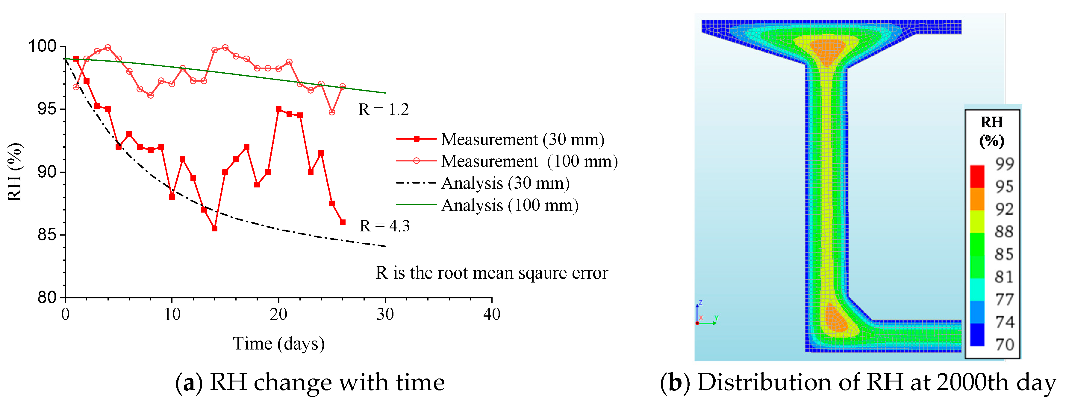
In this study, these measurements were used to calibrate and verify the concrete parameters for the moisture transport analysis. A half-section of the bridge with dimensions identical to the mid-span cantilever section of the Yuji River Bridge was modeled. The boundary condition was assigned such that moisture loss was allowed on all surfaces in contact with air, including the internal side of the box girder. The evaporation rate was calibrated to fit the experimental data. The atmospheric RH was assumed to be 70%. For the sake of simplicity, the diffusion coefficient of the concrete was assumed as constant and was calculated based on the atmospheric RH value.
Figure 3a shows a comparison of the RH changes with time based on analysis and measurement at depths of 30 and 100 mm. The diffusion coefficient of the concrete calculated for the assumed atmospheric RH value and the evaporation rate at the surface with a value of 3 × 10⁻⁹ m/s gave the best results. The figure shows that the results are in reasonably good agreement with the measured values as reported by Huang et al. [2]. The moisture distribution at the half-section of the bridge at 2000 days is presented in Figure 3b. It can be seen that the moisture content varies across the section according to the thickness of the members and exposure conditions. Hence, the shrinkage strain varies along the depth from the surface, resulting in additional curvature and deflection.

4.2. Calculation of Long-Term Deflection of Short-Span PSC Beam (Case A)

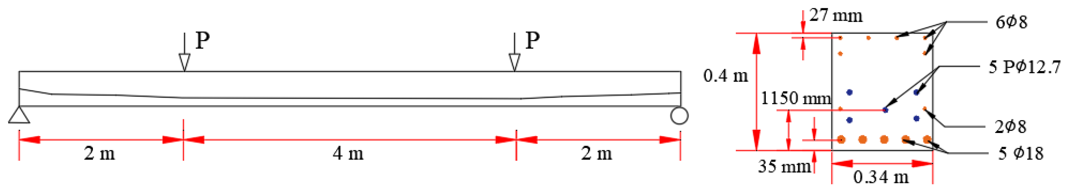
The first combined analysis was performed for a short-span PSC beam selected from a series of tests performed by Espion and Halluex between 1981 and 1986 at the University of Brussel [23]. The beam had a rectangular section of 0.34 × 0.4 m and a length of 8 m. The beam was prestressed with five strands (diameter 12.7 mm) with an effective area of 93 mm2. A prestressing stress of 1320 MPa was applied at 14 days. The dimensions and reinforcement details are shown in Figure 4.
In view of the symmetry of the section, a half-span of the beam was modeled to save computation time. Espion and Halluex reported that the compressive strength of the concrete at the time of prestressing was 32.4 MPa [23]. Accordingly, based on MC2010 [13], the material properties of concrete were assumed as follows: Young’s modulus E c = 32 GPa, mean compressive strength f c m = 33 MPa, uniaxial tensile strength f c t m = 2.56 MPa, and unit weight ρ c = 2350 kg/m3. For the prestressing and non-prestressing reinforcing bars, it was assumed that the elastic modulus E s was 200 GPa, and the unit weight ρ s was 7850 kg/m3.
Two quarter-point loads ( P ) of 16.5 kN and 63.75 kN were each applied to the beam for 28 days and 84 days, respectively. The tests were performed in a laboratory with an average RH and temperature of 60% and 20 °C, respectively. As the beam was kept in the laboratory during the test, the same evaporation rate (3 × 10⁻⁹ m/s) was assigned to all surfaces. Due to the absence of experimental data, the same evaporation rate with the case in 4.1, 3 × 10⁻⁹, is assumed. The moisture diffusion coefficient of the concrete was also assumed to be constant and was calculated for a constant RH value of 60%. The hydro-shrinkage constant was calibrated to fit the experimental data.
The resulting distribution of the RH across the beam section at different times is presented in Figure 5. Because the evaporation rate was assumed to be the same on all surfaces and the section is symmetrical, the RH values at the top and bottom surfaces are similar. This means that the deflection owing to nonuniform shrinkage is induced owing to the presence of a relatively larger area of reinforcement at the bottom section, as shown in 
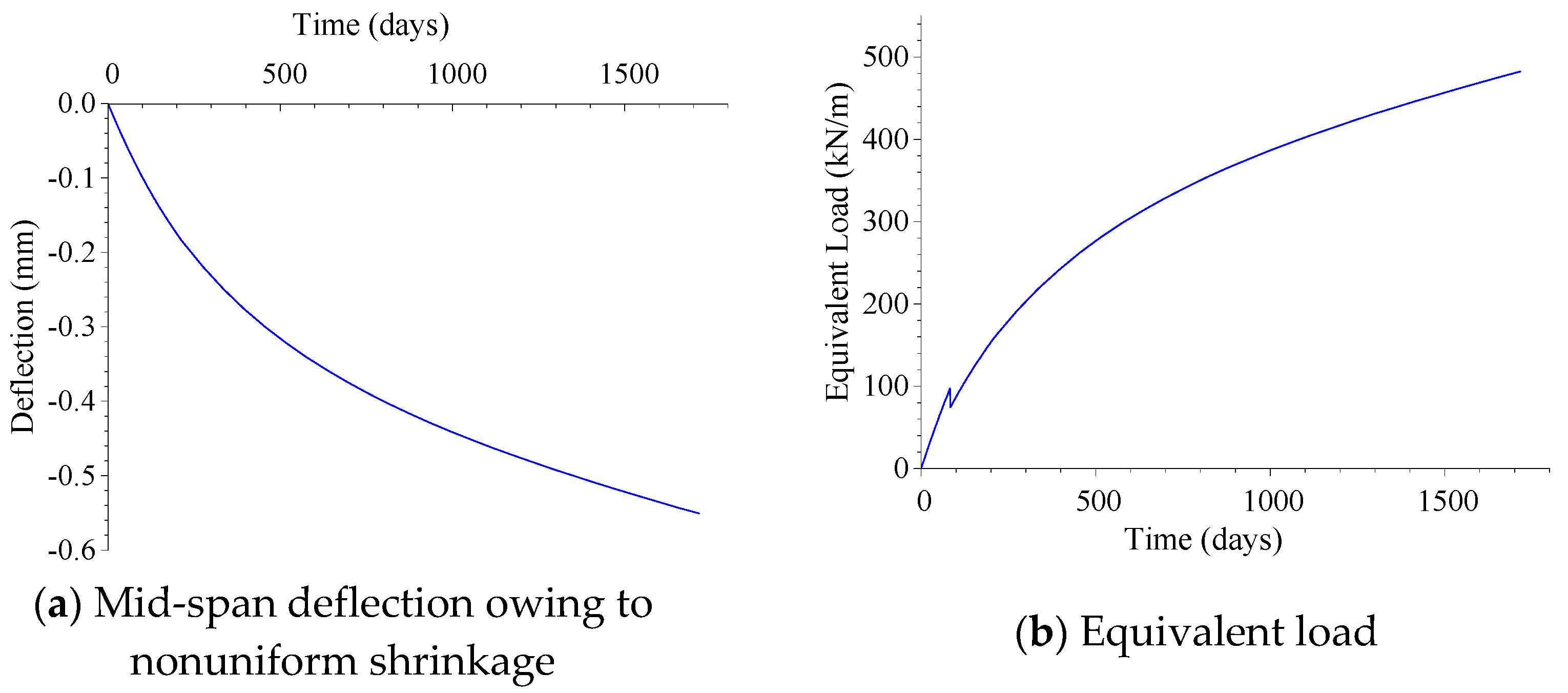
Figure 4. The prestressing and reinforcing bars are mostly located under the neutral axis of the beam section, which restricts the shrinkage strain at the bottom of the beam. Hence, the actual unrestricted strain of the top face of the beam becomes larger than that of the bottom face. As a result, a downward deflection is induced. The resulting deflection has a very small value, i.e., only 0.56 mm at the 1700th day, as shown in Figure 6a. Figure 6b shows the equivalent load calculated for the nonuniform shrinkage deflection in Figure 6a. The equivalent load at 84 days decreases as shown in Figure 6b because it is adjusted by a load adjusting factor γ a of 0.85 on the 84th day, i.e., the onset of cracking, which can be estimated from the structural analysis using Model-2. It should be noted that the negative deflection in Figure 6a indicates a downward deflection, whereas in Figure 6b, the positive equivalent load indicates the downward distributed load.
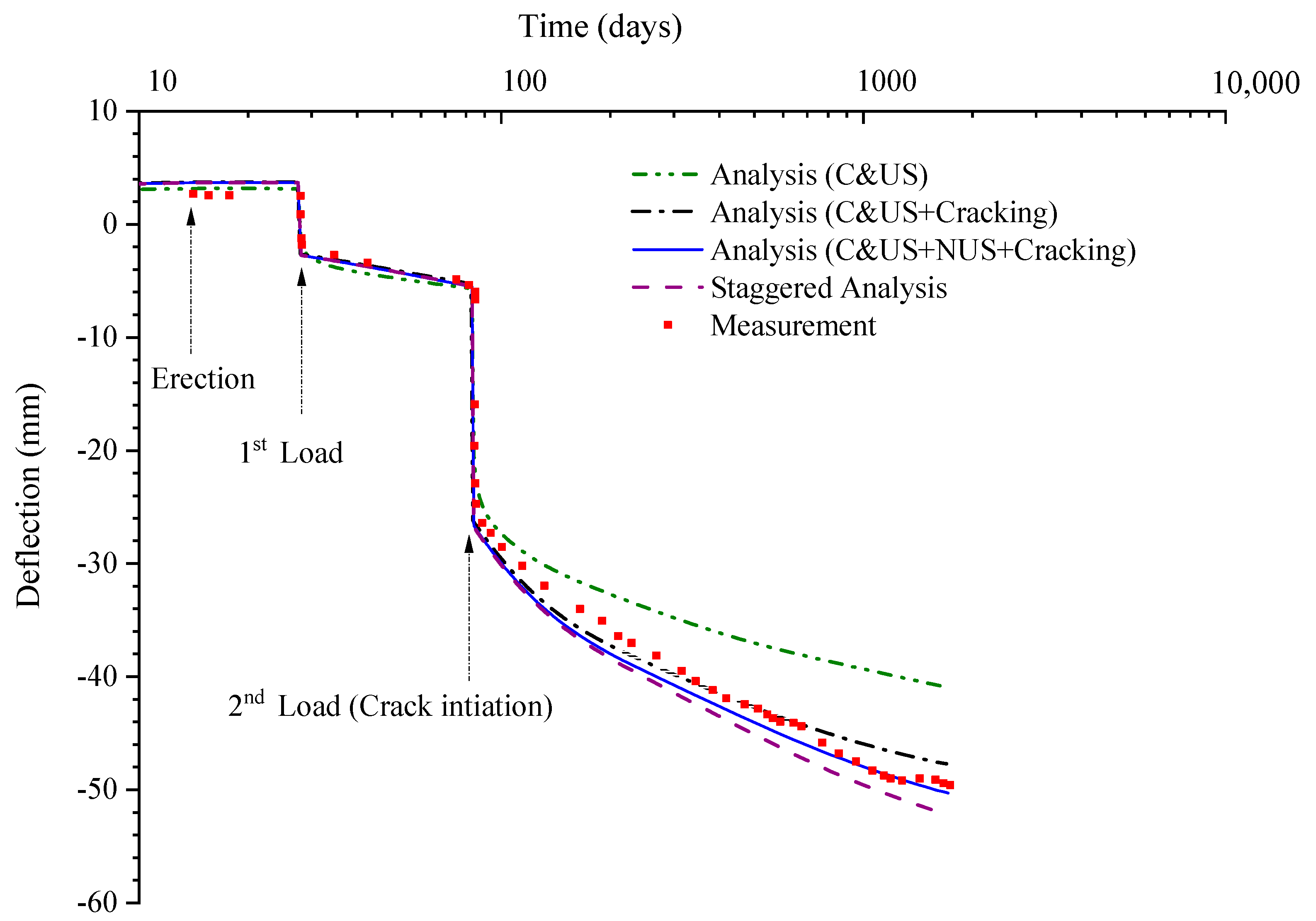
Figure 7 shows the change in the mid-span deflection with time. Four different approaches were used to calculate the deflection. The first used a built-in MC2010 model for the creep and uniform shrinkage (C&US) without considering cracking, as shown by the green line in Figure 7. The second considered creep and uniform shrinkage together with the stiffness reduction of concrete from cracking (C&US + Cracking), as shown by the black line in Figure 7. The third considered the effect of non-uniform shrinkage by using an equivalent load in addition to the combined effects of creep, uniform shrinkage, and cracking (C&US + NUS + Cracking), as shown by the blue line in Figure 7. The fourth approach was a staggered analysis shown by the purple line in Figure 7. The staggered analysis combined the potential flow and structural analyses provided by DIANA FEA [15,16]; the moisture analysis was directly linked to the subsequent nonlinear structural analysis. The hydro-shrinkage constant for the best fit to the measured deflection data was found to be 8 × 10⁻⁴.
The results in Figure 7 show that the analysis result from using the built-in MC2010 model code without considering cracking and nonuniform shrinkage (C&US) starts to diverge from the experimental data and other numerical results at the application of the second load (which induces cracks), and exhibits considerable differences from the measured data at later stages. On the contrary, the analyses considering cracking provide values closer to the measured data (shown with red square dots). The stiffness degradation of the beam owing to the cracking of the concrete significantly increased the long-term deflection. In addition, cracks grow and propagate owing to the creep and nonuniform shrinkage. To demonstrate the effects of creep and nonuniform shrinkage on the crack propagation, an additional crack analysis was performed without considering the creep. Figure 8 shows the crack strain at the bottom of the beam when the second load was applied (84th day) and at the end of the analysis period (1750th day). In the analysis considering neither creep nor nonuniform shrinkage, the crack strain does not show any change after the application of the second load. In contrast, under the influence of creep and nonuniform shrinkage, the crack strain not only increases but also extends to a wider region. This further reduces the stiffness of the beam. In addition, the nonuniform shrinkage contributes to the increase in deflection. The final deflection owing to the non-uniform shrinkage alone is only 0.56 mm from the moisture transport analysis as shown in Figure 6a but grows to 2.4 mm on the 1700th day, when the resulting equivalent load is added to the other loads in Model-2. This is also owing to the combined actions of the cracking and creep. Consequently, the analysis using the equivalent load for nonuniform shrinkage in combination with creep, uniform shrinkage, and cracking (C&US+NUS+Cracking) provides the results closest to the measured data.
As depicted in Figure 7, the staggered analysis also gives results close to the measured data (and the results of the equivalent load analysis (C&US+NUS+Cracking)). However, the stress distributions in the staggered analysis and equivalent load analysis are not identical. In the staggered approach, additional tensile stress is developed because the differential drying shrinkage is restrained by the surrounding concrete and reinforcements; i.e., the stress is in the opposite direction of the shrinkage strain. In contrast, in the equivalent load analysis, stress is induced in the same direction as the flexural strain induced by the equivalent load. In this case, however, the reinforcement ratio is larger in the lower part of the section. Hence the shrinkage strain at the bottom is more restrained than that at the top. Thus, higher compressive strain occurs at the top than at the bottom, and the tensile strain and stress occurs at the bottom. This is same in the equivalent load analysis. There must be some differences in the amplitude of strain and stress in the staggered analysis and equivalent load analysis. However, the restraint to the shrinkage strain is small due to relatively small reinforcement ratio. Therefore, tensile stress is compared to the total stress in the beam faces including the self-weight, prestressing force, and applied loads, the stress difference between the staggered analysis and equivalent load analysis is very small and does not make a significant difference. The difference in the tensile stress between the staggered analysis and the equivalent load approach was less than 0.2 MPa and that in the deflection was less than 1.9 mm at the end of the analysis period.
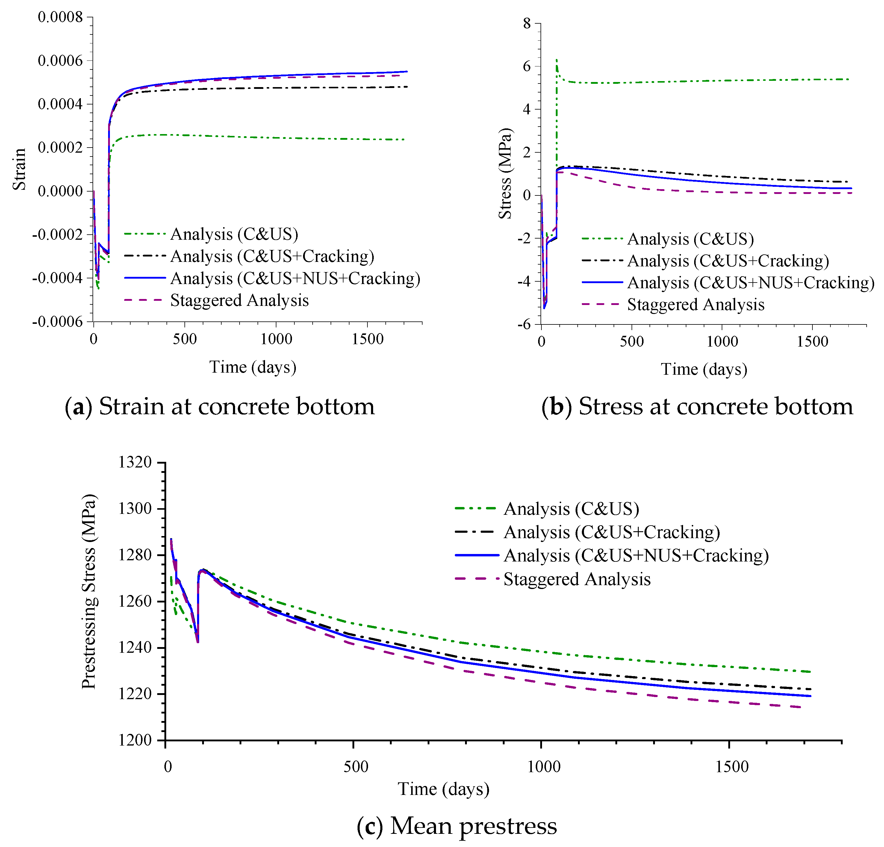
Figure 9 shows the variations of the strain and stress of the concrete bottom and mean prestress at the mid-span section with time. As shown in Figure 9a, in all analyses, the tensile strain occurs at the bottom after 84 days. The tensile strains from the staggered analysis and equivalent load analysis (C&US+NUS+Cracking) are the largest owing to the non-uniform shrinkage. However, as shown in Figure 9b, the tensile stresses are smaller in the analyses considering cracking because the cracks relieve stress. The tensile stresses from the staggered analysis are the smallest owing to the larger deflection and larger crack strain. In addition, as shown in Figure 9c, the staggered analysis gives the lowest prestress. This suggests that the total shrinkage strain (uniform plus non-uniform shrinkage) is larger at the center of the prestressing tendons in the staggered analysis than in the equivalent load analysis.

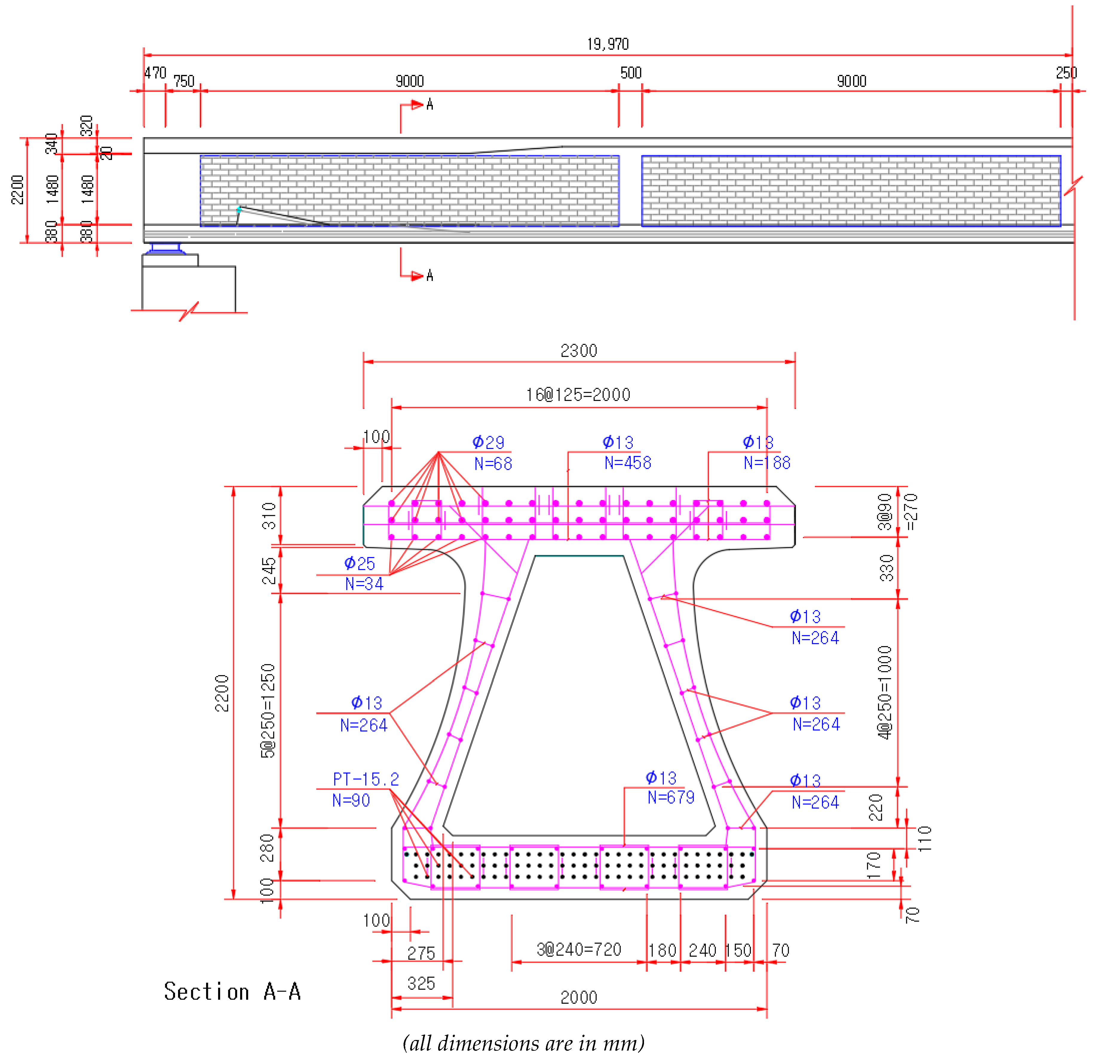
4.3. Calculation of Long-Term Deflection of Medium-Span PSC Box Girder (Case B)

The second example analysis was performed for a 40-m span precast PSC box girder bridge for railways located in Osong, South Korea. It was erected at the end of 2017. The girder has a total height of 2.2 m. The thickness of the bottom slab is 0.34 m, and that of the top slab is 0.37 m. The details of the shape and dimensions of the girder are shown in Figure 10.
The compressive strength of the concrete cylinder was 50 MPa. The modulus of elasticity and the tensile strength of the concrete were calculated as 41.6 GPa and 4.1 MPa, respectively, according to MC2010 [13]. The moduli of both the non-prestressing and prestressing rebar were set to 200 GPa.
The prestressing force was applied using ninety 15.2-mm diameter bars in three layers. The yield strength of each bar was 1600 MPa with an allowable stress of 1502 MPa. The design applied stress was assumed to be 87% of the allowable stress, i.e., 1308 MPa. In the model, an effective stress of 1250 MPa was applied while assuming an immediate loss of 4% owing to the combined effects of the elastic shortening, friction, and anchorage slip.
The half-span and half-section of the bridge were modeled in DIANA FEA while using the advantages of symmetry. A total of 3817 quadratic hexahedron elements were used for the half concrete girder section. The prestressing and longitudinal reinforcing bars were modeled using 45 and 41 bar elements, respectively. In addition, for the transverse bar and stirrups, 2423 bar elements were used. Figure 11 shows the 3D FE model for the medium-span PSC box girder.
The daily average temperature at the site was lowest at −4 °C in January and highest at 24 °C in July. The annual average RH was approximately 68.5%. Accordingly, the average atmospheric RH was set to 68.5% in the moisture transport analysis. The moisture diffusion coefficient of the concrete was calculated for a constant RH value of 69%. The evaporation rate was assumed to be 3 × 10⁻⁹ m/s for the top and outer side faces of the girder. To account for the different environmental exposure conditions such as sunlight, the evaporation rate through the bottom and inner faces of the box girder was set to 50% of that of the top and the outer side faces. The hydro-shrinkage constant value was calibrated for the best fit to the measured data.
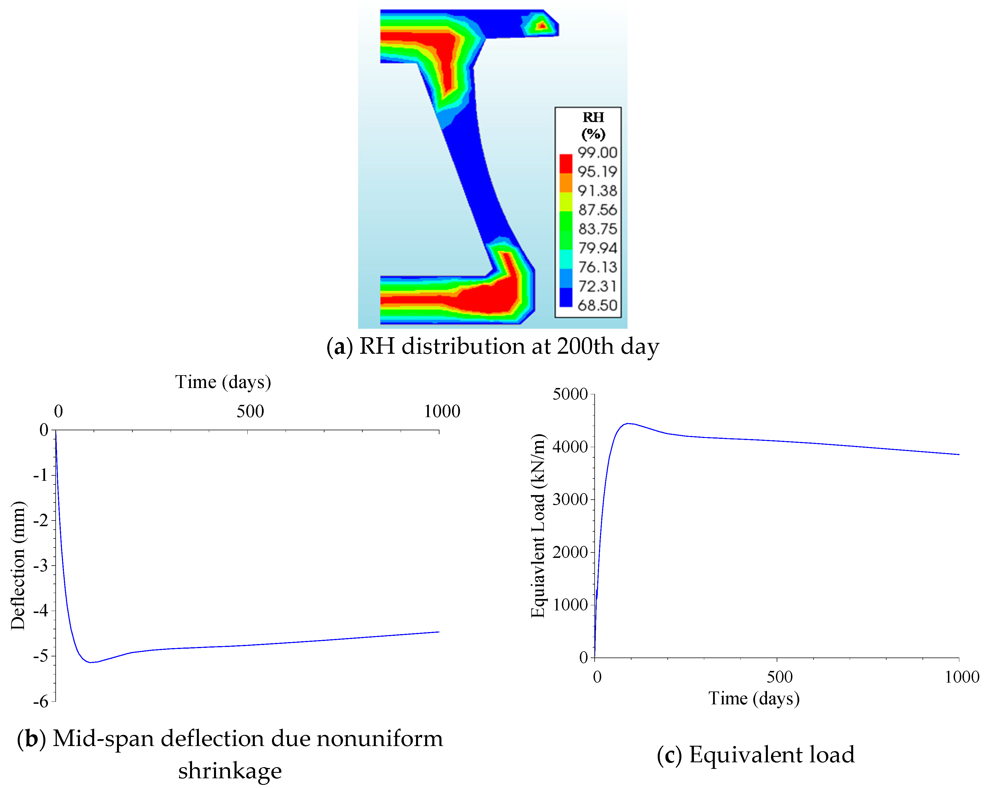
Figure 12a shows the results from the moisture distribution analysis on the 200th day. The lower web section of the girder, which is thinner, dried out faster. Figure 12b shows the variation in the mid-span deflection owing to the nonuniform shrinkage strain. It rises to a peak value of 5.1 mm after 120 days and then slowly decreases to 4.5 mm on the 1000th day, as the moisture level gradually equilibrates with the atmosphere. As the girder is almost prismatic, the resulting equivalent load has the same profile as the deflection-time curve (see Figure 12c).
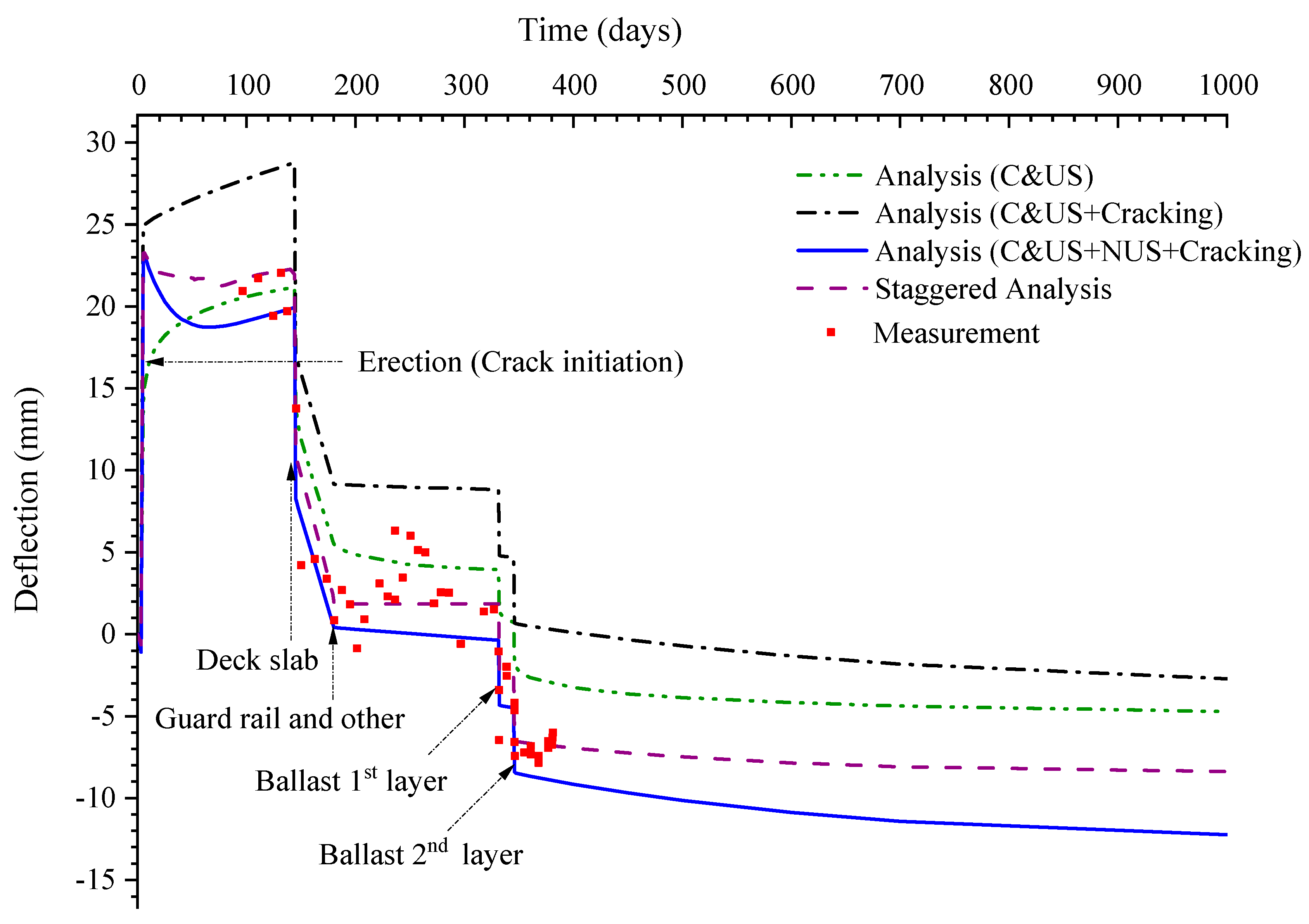
In the structural analysis using Model-2, the loads were applied according to the construction history of the bridge. The self-weight and prestressing force were applied on the 5th day. The deck slab was placed on the 150th day, and other permanent loads (excluding the railway track) were added between the 145th and 180th days. The first and second layers of the ballast were installed on the 332nd and 346th days, respectively. The load adjusting factor for the equivalent load (0.75) was applied after crack initiation on the 5th day.
The deflection of the girder was measured for 380 days [24]. The variations in the mid-span deflection with time by different analysis methods are presented in Figure 13. The hydro-shrinkage constant for the best fit of the results of the equivalent load analysis (C&US+NUS+Cracking) was found to be 3 × 10⁻³. The higher hydro-shrinkage constant value (relative to that for the short-span PSC beam (case A)) is attributed to the higher environmental RH as pointed out by Alvarado [22], and the use of ground-granulated blast furnace slag as a concrete binder.
As can be seen in Figure 13, the staggered analysis and combined analysis using the equivalent load for nonuniform shrinkage (C&US+NUS+Cracking) gave the results closest to the measured data up to 380 days. In contrast, the analysis using the built-in MC2010 model for creep and uniform shrinkage (C&US) without considering cracking and the analysis considering creep and uniform shrinkage together with a stiffness reduction of the concrete by cracking (C&US+Cracking) failed to predict the long-term deflection. The cracking initiates in the support area, when the self-weight and the prestressing force is applied on the 5th day (see Figure 14). The analysis without considering cracking (C&US) results in a lower upward deflection (camber) at the erection relative to the other analyses. The analysis considering cracking but not nonuniform shrinkage (C&US+Cracking) overestimates the upward deflection. The nonuniform shrinkage has a more significant contribution to the downward deflection throughout the analysis period than that in the short-span PSC beam case (case A) owing to the larger girder section. The final deflection owing to nonuniform shrinkage alone is only 4.5 mm in the moisture transport analysis but is raised to 9.5 mm in the combined analysis (C&US+ NUS+Cracking) and to 5.7 mm in the staggered analysis, owing to the combined action of cracking and creep as discussed in Section 4.2.
The difference between the results of the staggered analysis and those of the equivalent load analysis (C&US + NUS + Cracking) is larger than that in the short-span PSC beam (case A) described in Section 4.2. The difference was 0.7 MPa in the compressive stress values and 3.8 mm the deflection values at the end of the analysis period. Additionally, unlikely to be the case in 4.2, the upward deflection by the staggered analysis is larger than that by the equivalent load analysis, and the final deflection by the staggered analysis is smaller. This is because there are more reinforcing bars that are uniformly distributed in the top and bottom flanges in this PSC box girder than in the short-span PSC beam. That is, restraint to shrinkage strain is higher, and the downward or upward deflection is more restrained by the well-distributed reinforcements with higher reinforcement ratio. Therefore, smaller additional tensile strain due to nonuniform shrinkage occurs at the bottom of the girder in the staggered analysis than that in the equivalent load analysis. Additional tensile stress is induced at the top flange and additional compressive stress is induced at the bottom of the girder. This stress distribution is opposite to that in the equivalent load analysis. Consequently, larger upward deflection is obtained in the staggered analysis (as compared to the equivalent load analysis) as shown in Figure 13. This suggests that the section shape, dimensions, and reinforcement details considerably affect the nonuniform shrinkage induced deflection of the PSC girder.
Shear cracking is visible at erection but only in the support area. The other section remains uncracked for the entire analysis period, as shown in Figure 14. Thus, the significance of the stiffness reduction owing to cracking is minimal at later stages.
Figure 15 shows the stress and strain at the bottom concrete and the mean prestress at the mid-span section of the girder. As shown in the figure, the girder section remains in compression at the mid-span section throughout the analysis period. The compressive strain in the staggered analysis is the largest because of the compressive shrinkage strain at the bottom, whereas the equivalent load induces a tensile stress and strain at the bottom unlike in the staggered analysis, as explained earlier in Section 4.2. Thus, the equivalent load analysis yields the smallest compressive stress and strain, as shown in Figure 15a,b. As the prestress loss is a multiple of strain changes and the elastic modulus of the prestressing tendon, it follows the same curve as that of the compressive strain of the concrete (see Figure 15c). Due to creep, the compressive strain at the bottom increases with increasing deflection as shown in Figure 15a, but, as can be found in Figure 15b, the stress at the bottom concrete becomes almost constant after 346 days in the analyses without considering nonuniform shrinkage. Since creep does not develop stress, the stress change after all fixed loads are imposed is mainly due to non-uniform shrinkage. In the equivalent load analysis, the additional tensile stress at the bottom due to the nonuniform shrinkage is reducing slowly as the moisture distribution is converging to equilibrium state with the environment RH, and thus, the compressive stress is increasing slowly. Whereas, in the staggered analysis, the compressive stress at the bottom increases due to restraint.

4.4. Long-Term Deflection of Long-Span Cantilever PSC Bridge (Koror–Babeldaob Bridge) (Case C)

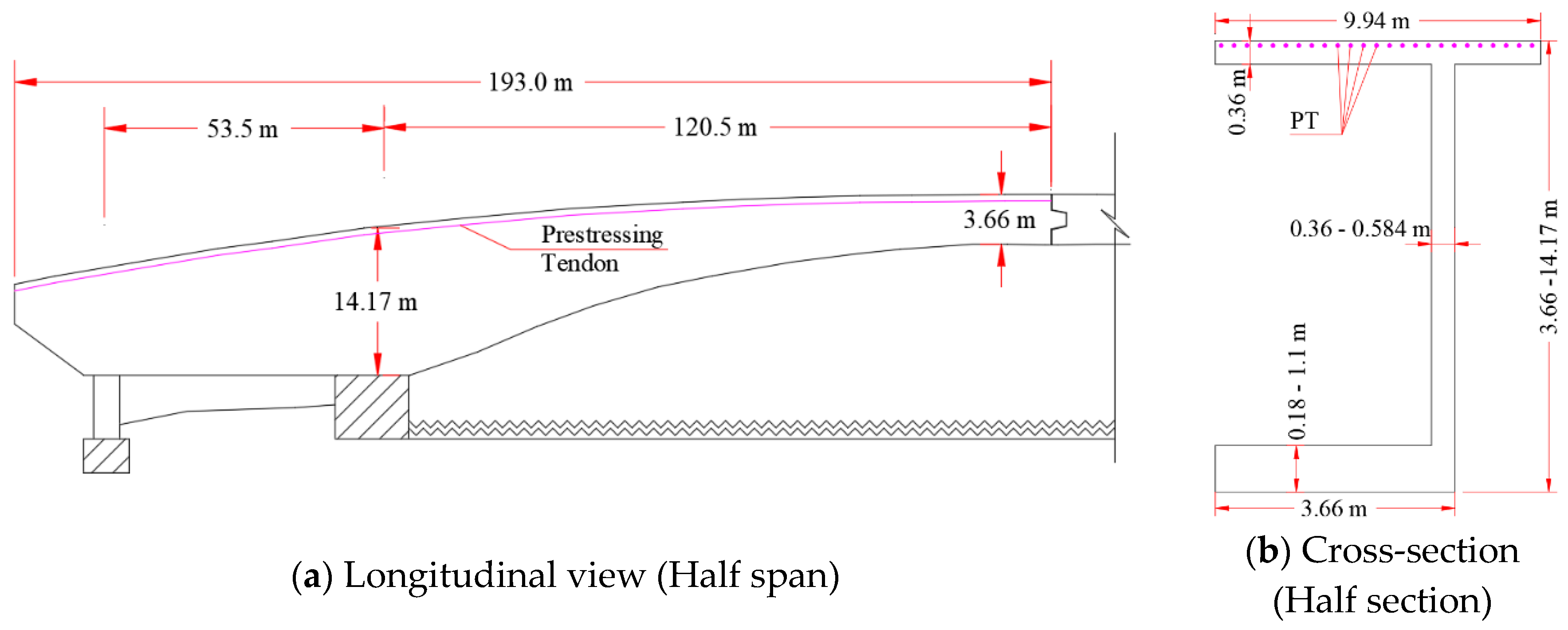
The third example analysis was conducted for a long-span PSC bridge. The Koror–Babeldaob Bridge, with a main span of 241 m, was built in 1977 using a cantilever method. It collapsed in 1996, three months after remedial prestressing. The final mid-span deflection in design was expected to be in the range of 0.53 to 0.65 m. However, after 18 years, it reached 1.39 m and continued to increase until it collapsed on September 26, 1996 [25]. The main span of the bridge comprised a pair of large cantilevers connected with a sliding hinge to allow relative longitudinal movements [26].
The specified compressive strength of the concrete was 35 MPa. In the design, the allowable tensile stress was set to zero [26]. The 28-day elastic modulus of the concrete in the initial design was assumed as 28.3 GPa according to AASHTO [10]; however, various studies have reported that the actual value was in the range of 19.6 to 22 GPa [26,27]. The average unit weight of the concrete was reported as 23.5 kN/m3. In the model, the elastic moduli of both the non-prestressing and prestressing bars were set as 200 GPa, whereas that of concrete was assumed to be 22 GPa in the user-defined material. The uniaxial tensile strength of the concrete was calculated as 3.2 MPa, according to MC2010 [13]. The detailed dimensions of the bridge girder are shown in Figure 16. In the area where the bridge was built, the annual average temperature was approximately 28 °C, and the annual average RH was approximately 82% [26].
Using high-strength threaded bars with a diameter of 32 mm and strength of 1050 MPa, the prestress of 735 MPa, 70% of the tensile strength of the bar, was applied. The same bars were used to provide vertical prestress for the webs with spacing varying from 300 to 3000 mm and the horizontal transverse prestress of the top slab, with a typical spacing of 560 mm [25]. The average thickness of the concrete pavement at the top slab was 75 mm.
The half-span of the bridge was modeled with half-section using DIANA FEA with the advantage of symmetry. A total of 17,432 quadratic hexahedron elements were used for the girder, and 158, 344, and 121 bar elements were used to model the longitudinal, lateral, and vertical prestressing bars, respectively. In addition, 1373 bar elements were used to model the non-prestressing reinforcing bars for the half-concrete girder section excluding the supports. Figure 17 shows the 3D FE model for the Koror–Babeldaob Bridge.
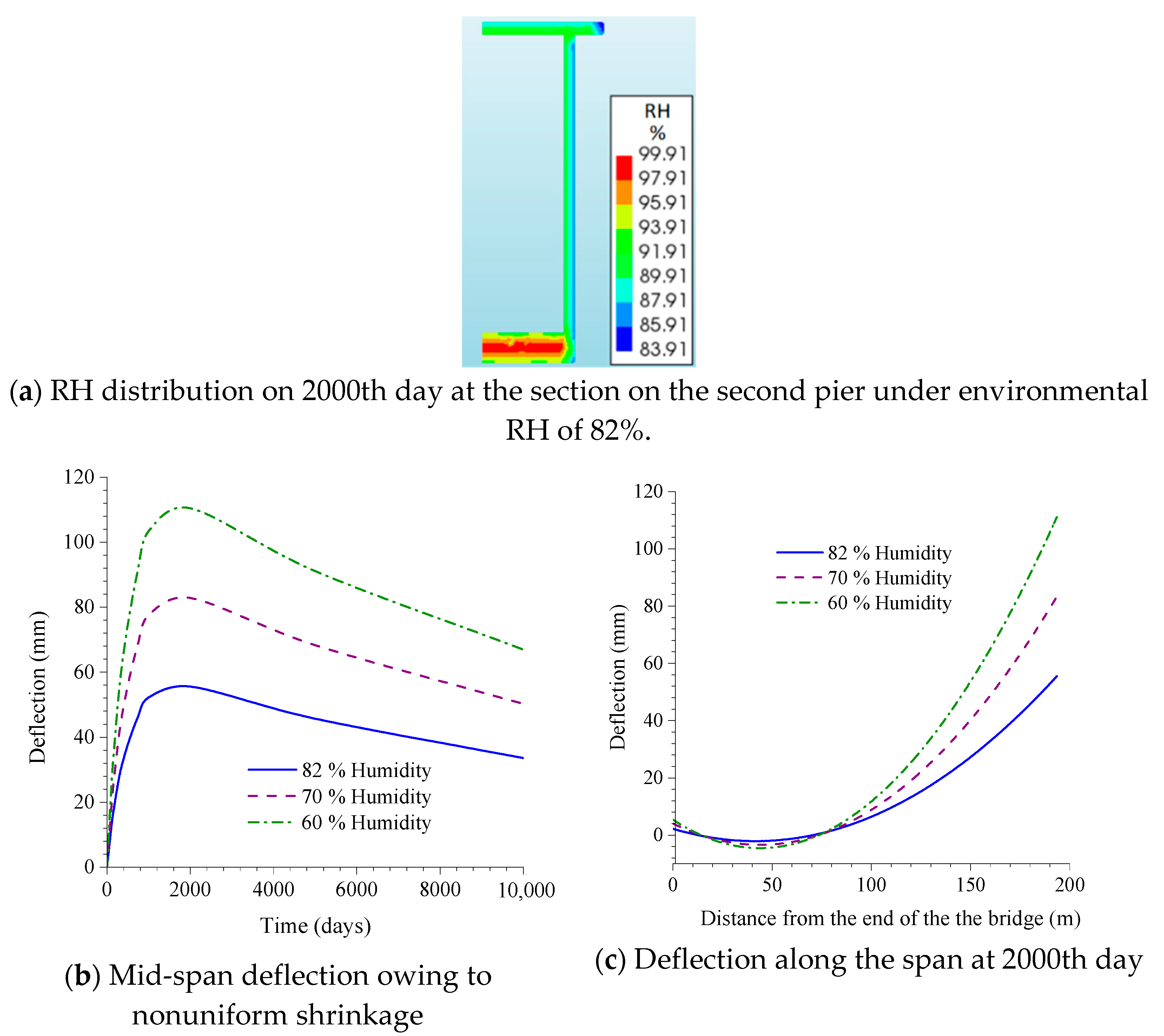
To study the effect of the environmental RH on the deflection owing to the non-uniform shrinkage, in the moisture transport analysis using Model-1, the average atmospheric RH was set as 60% and 70%, in addition to the reported value of 82%. The evaporation rate was assumed to be 3 × 10⁻⁹ m/s, and the hydro-shrinkage constant value was calibrated for the best fit to the measured data. The moisture diffusion coefficient was calculated for an RH value of 82%.
The analysis result in Figure 18 shows that the deflection owing to the non-uniform shrinkage is upward owing to the cantilever arrangement of the bridge and rises up to 55.5 m on the 2000th day when exposed to 82% RH. After that, as the RH inside the concrete approaches equilibrium with the atmospheric RH, the deflection slowly decreases to a final value of 33.5 m at the end of the analysis period. As the atmospheric RH decreases, the resulting deflection (in this case, the camber) caused by the nonuniform shrinkage increases, as shown in Figure 18.
As the bridge is non-prismatic, the second moment of area of its section is calculated at every meter along the length of the bridge, as shown in Figure 19a. The deflection owing to the non-uniform shrinkage is extracted every 0.5 m at the top slab and is formulated as a function of the length of the bridge. From this data, the moment and equivalent load are derived, as shown in Figure 19c,d.
In the structural analysis using Model-2, because the bridge was built using a segmental construction method, the self-weight and prestressing load were gradually applied for 220 days. Other permanent loads, such as the weight of the pavement and guardrail load, were applied 20 days after the completion of the segmental construction. The total analysis period was 10,000 days. The load adjusting factor for the equivalent load was calculated as 0.8 and was applied on the 14th day.
In Figure 20, the analysis results are compared against the measured data (shown by the red squares) and the original design calculation (shown with the purple line). The original estimation of the deflection was calculated using a simplified approach based on the American Association of State Highway Officials design guidelines [26]. In this approach, the creep and shrinkage are assumed to start after the completion of bridge construction. Accordingly, the elastic deflection owing to all permanent loads is calculated first, and the long-term deflection is estimated by multiplying the elastic deflection by the assumed creep coefficient. The total elastic deflection after an assumed 10% prestress loss was 370 mm, and multiplying this by a creep coefficient of 1.3 gave the final long-term deflection as 481 mm.
Figure 20 shows the results for the deflection calculation using different methods. As shown, the analyses considering cracking provide results that are very close to the measured data. The relatively steeper slope in the period from the 30th to 220th day in the analyses considering cracking is caused by the gradual increment of permanent loads during this period. In contrast, the results from the analysis using the built-in MC2010 model show a long-term deflection under 250 mm, which is the lowest value and is too far away from the measured data. This indicates that a design and analytic approach that does not consider cracking (even a current one) cannot correctly predict an excessive deflection in a case where the stiffness degradation owing to cracking is the main cause of the excessive deflection.
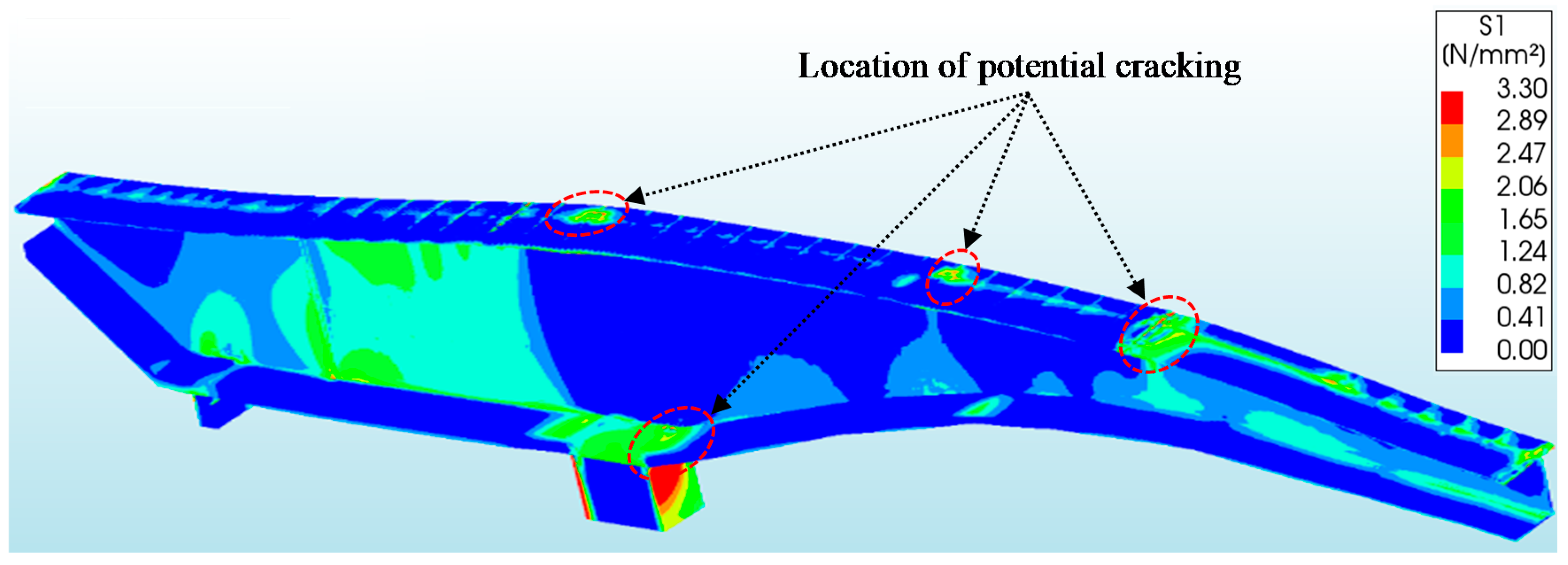
The cracking starts at the face of the second pier and at a location 66 m away from that point, as shown in Figure 21. The principal stress exceeds the tensile strength of concrete, i.e., 3.2 MPa. This is in good agreement with the report by Tang [26], i.e., cracking and failure occur near the same location.
The nonuniform shrinkage induced deflection is upward, and thus, the final deflection from the equivalent load analysis (C&US+NUS+Cracking) is less than that from the analysis without considering the non-uniform shrinkage (C&US+Cracking). However, it is worth noting that the nonuniform shrinkage induces a considerable amount of additional deflection in long-span PSC bridges. It is expected that this additional deflection induces more cracks, further reducing the stiffness of the girder, and consequently, enhances the long-term deflection.

5. Conclusions

In this study, 3D FE modeling and analysis were performed for short-, medium-, and long-span bridges to calculate the long-term deflections of PSC bridges considering the combined effects of creep, shrinkage, and cracking of concrete. To consider the nonuniform shrinkage effect, a simplified method using an equivalent load is proposed herein. After performing a moisture transport analysis and calculating the resulting deflection owing to the nonuniform shrinkage strain, the equivalent load for producing the same deflection is calculated. The equivalent load is then applied to a model for a combined nonlinear structural analysis incorporating creep, uniform shrinkage, and cracking to thereby calculate the long-term deflections of PSC bridges. From several example analyses in this study; the following conclusions can be drawn:
(1)
Nonuniform shrinkage contributes to a significant portion of the long-term deflection of PSC bridges, especially in medium- to long-span bridges with large girder sections.
(2)
The cracking of concrete has a significant impact on the long-term deflections of PSC bridges because it reduces the stiffness of the girder. In addition, the deflection caused by the nonuniform shrinkage induces more cracks and enhances them to propagate, resulting in an increase in the long-term deflection owing to the combined action of the creep.
(3)
The equivalent load approach yields results very close to the experimental data by incorporating the above-mentioned nonuniform shrinkage effect, especially for lightly reinforced PSC girders. For heavily reinforced PSC girders, however, the equivalent load approach shows a slight deviation from the experimental data owing to the increased restraint from reinforcements. Therefore, the arrangement and number of reinforcements are crucial for predicting the nonuniform-shrinkage-induced deflection by the equivalent load method.
(4)
Despite a slight deviation in the calculated deflections of heavily reinforced PSC girders, the results can be on the safe side for the design calculation, and therefore, this approach is very effective for calculating long-term deflections while considering the nonuniform shrinkage strain, without the need for the complicated and expensive coupling of moisture transport and structural analyses.

Author Contributions

Conceptualization, F.N.B. and S.Y.J.; methodology, F.N.B. and S.Y.J.; software, F.N.B.; validation, F.N.B., S.Y.J. and S.-I.K.; formal analysis, F.N.B.; investigation, F.N.B.; resources, F.N.B. and S.Y.J.; data curation, F.N.B.; writing—original draft preparation, F.N.B.; writing—review and editing, F.N.B. and S.Y.J.; visualization, F.N.B. and S.Y.J.; supervision, S.Y.J. and S.-I.K.; project administration, F.N.B., S.Y.J. and S.-I.K.; funding acquisition, S.Y.J. and S.-I.K. All authors have read and agreed to the published version of the manuscript.

Funding

This research was supported by the Doctoral Program of the University of Science and Technology (UST) and the R&D program of Korea Railroad Research Institute, Republic of Korea.

Acknowledgments

We would like to thank Ki Hyun Kim (Senior Researcher, Korea Railroad Research Institute) for sharing his insight and experiences in the numerical analysis.

Conflicts of Interest

The authors declare no conflict of interest.

References

  1. Tong, T.; Liu, Z.; Zhang, J.; Yu, Q. Long-term performance of prestressed concrete bridges under the intertwined effects of concrete damage, static creep and traffic-induced cyclic creep. Eng. Struct. 2016, 127, 510–524. [Google Scholar] [CrossRef]
  2. Huang, H.; Garcia, R.; Guadagnini, M.; Pilakoutas, K. Effect of section geometry on development of shrinkage induced deformation in box girder bridges. Mater. Struct. 2017, 50, 222. [Google Scholar] [CrossRef] [Green Version]
  3. Maekawa, K.; Chijiwa, N.; Gebreyouhannes, E. Multi-scale simulation of thermo-hygro mechanics of RC-PC structures under long-term actions. In Proceedings of the International Conference on Recent Advances in Nonlinear Models—Structural Concrete Applications, Coimbra, Portugal, 24–25 November 2011. [Google Scholar]
  4. Yu, Q.; Bazant, Z.; Wan-Wendner, R. Improved Algorithm for Efficient and Realistic Creep Analysis of Large Creep-Sensitive Concrete Structures. ACI Struct. J. 2012, 109, 665–676. [Google Scholar]
  5. Li, S.; Yang, Y.; Pu, Q.; Yang, D.; Sun, B.; Li, X. Three- dimensional nonlinear creep and shrinkage effects of long-span prestressed concrete box girder bridge. Struct. Concr. 2019, 20, 638–649. [Google Scholar] [CrossRef]
  6. ACI. ACI Committee 435, 435R-95: Control of Deflection in Concrete Structures (Reapproved 2000); ACI: Farmington Hills, MI, USA, 2002. [Google Scholar]
  7. AASHTO LRFD Bridge Design Specifications; American Association of State Highway and Transportation Officials: Washington, DC, USA, 2012.
  8. Rots, J.G.; Blaauwendraad, J. Crack Models for Concrete, Discrete or Smeared? Fixed, Multi-Directional or Rotating? Faculty of Civil Engineering, Delft University of Technology: Delft, The Netherlands, 1989. [Google Scholar]
  9. Allam, S.M.; Shoukry, M.S.; Rashad, G.E.; Hassan, A.S. Evaluation of tension stiffening effect on the crack width calculation of flexural RC members. Alex. Eng. J. 2013, 52, 163–173. [Google Scholar]
  10. ACI. ACI Committee 224, 224R-01: Control of Cracking in Concrete Structures (Reapproved 2008); ACI: Farmington Hills, MI, USA, 2001. [Google Scholar]
  11. Křístek, V.; Bazant, Z. Shear Lag Effect and Uncertainty in Concrete Box Girder Creep. ASCE J. Struct. Eng. 1987, 113, 557–574. [Google Scholar] [CrossRef]
  12. Precast/Prestressed Concrete Bridge Design Manual; Precast/Prestressed Concrete Institute (PCI): Chicago, IL, USA, 2003.
  13. Model Code 2010—First Complete Draft, Vol. 1; International Federation for Structural Concrete (fib): Lausanne, Switzerland, 2010.
  14. Eurocode 2. Design of Concrete Structures. Concrete Bridges. Design and Detailing Rules, BSI Standards. 2005. Available online: https://infostore.saiglobal.com/preview/is/en/2005/i.s.en1992-2-2005.pdf?sku=677898 (accessed on 23 September 2020).
  15. DIANA FEA. DIANA Documentation Release 10.3.; DIANA FEA: Delft, The Netherlands, 2019. [Google Scholar]
  16. Manie, J.; Kikstra, P.W. (Eds.) DIANA Finite Element Analysis User’s Manual: Material Library. TNO DIANA BV, 2014. Available online: https://dianafea.com/manuals/d95/MatLib/MatLib.html (accessed on 23 September 2020).
  17. Ali, W.; Urgessa, G. Computational Model for Internal Relative Humidity Distribution in Concrete. J. Comput. Eng. 2014, 2014, 539850. [Google Scholar] [CrossRef] [Green Version]
  18. Kim, J.K.; Lee, C. Prediction of differential drying shrinkage in concrete. Cem. Concr. Res. 1998, 28, 985–994. [Google Scholar] [CrossRef]
  19. Kuryłowicz-Cudowska, A.; Wilde, K.; Chróścielewski, J. Prediction of cast-in-place concrete strength of the extradosed bridge deck based on temperature monitoring and numerical simulations. Constr. Build. Mater. 2020, 254, 119224. [Google Scholar] [CrossRef]
  20. Bernard, O.; Brühwiler, E. The effect of reinforcement in the new layer on hygral cracking in hybrid structural elements. Mater. Struct. 2003, 36, 118–126. [Google Scholar] [CrossRef] [Green Version]
  21. Sadouki, H.; Mier, J. Simulation of hygral crack growth in concrete repair systems. Mater. Struct. 1997, 30, 518–526. [Google Scholar] [CrossRef]
  22. Alvaredo, A. Crack Formation under Hygral or Thermal Gradients. In Proceedings of the International Conference on Fracture Mechanics of Concrete Structures (FraMCoS2), Zürich, Switzerland, 25–28 July 1995; Volume 3, pp. 1423–1441. [Google Scholar]
  23. Espion, B.; Halleux, P. Long Term Behavior of Prestressed and Partially Prestressed Concrete Beams: Experimental and Numerical Results; ACI: Farmington Hills, MI, USA, 1991. [Google Scholar]
  24. Lee, Y.J.; Sim, S.H.; Lee, J.H.; Lee, J.B. Field Test for Monitoring of Long-term Deformation of ART-Girder Bridge in Osong Test Line. Research Report, Ulsan National Institute of Science and Technology; Korea Railroad Research Institute: Uiwang-si, Korea, 2018. [Google Scholar]
  25. Şener, S.; Çağlar, Y.; Benzer, M.A.; Şener, K.C. Vertical displacement of collapsed bridge in Palau. Chall. J. Struct. Mech. 2015, 1, 84–89. [Google Scholar]
  26. Tang, M.C. The Story of the Koror Bridge; International Association for Bridge and Structural Engineering (IABSE): Zurich, Switzerland, 2014. [Google Scholar]
  27. Bazant, Z.; Yu, Q.; Li, G.H. Excessive Long-Time Deflections of Prestressed Box Girders. I: Record-Span Bridge in Palau and Other Paradigms. ASCE J. Struct. Eng. 2012. [Google Scholar] [CrossRef] [Green Version]
  28. Burgoyne, C.; Scantlebury, R. Lessons learned from the bridge collapse in Palau. Proc. Inst. Civil Engineers Civil Eng. 2012, 161, 28–34. [Google Scholar] [CrossRef] [Green Version]
Figure 1. Curvature and strain profile of a beam.
Applsci 10 07754 g001
Figure 2. Exponential tension softening diagram.
Applsci 10 07754 g002
Figure 3. Comparison of relative humidity change with time and distribution of relative humidity at the mid-span of cantilever section.
Applsci 10 07754 g003
Figure 4. Longitudinal and cross-sectional view of the short-span prestressed concrete (PSC) beam.
Applsci 10 07754 g004
Figure 5. Relative humidity (RH) distribution along the section of the short-span PSC beam.
Applsci 10 07754 g005
Figure 6. Mid-span deflection owing to nonuniform shrinkage and equivalent load for the short-span PSC beam.
Applsci 10 07754 g006
Figure 7. Variation of mid-span deflection of the short-span PSC beam.
Applsci 10 07754 g007
Figure 8. Distribution of crack strain of the short-span PSC beam at 84th and 1750th days. (a) Cracking only; (b) C&US+Cracking; (c) C&US+NUS+Cracking.
Applsci 10 07754 g008
Figure 9. Variation of strain and stress of concrete bottom and mean prestress at the mid-span section with time in the short-span PSC beam.
Applsci 10 07754 g009
Figure 10. Longitudinal and cross-sectional view of medium-span PSC box girder.
Applsci 10 07754 g010
Figure 11. Three-dimensional (3D) finite element (FE) model for the medium-span PSC girder.
Applsci 10 07754 g011
Figure 12. RH distribution in the girder section and variation of mid-span deflection owing to nonuniform shrinkage and equivalent load with time in the medium-span PSC box girder.
Applsci 10 07754 g012
Figure 13. Variation of mid-span deflection with time in the medium-span PSC box girder.
Applsci 10 07754 g013
Figure 14. Distribution of crack strain of the medium-span PSC box girder at 6th, 144th, and 1000th days. (a) Cracking only; (b) C&US + Cracking; (c) C&US + NUS + Cracking.
Applsci 10 07754 g014
Figure 15. Variation of strain and stress of concrete bottom and mean prestress at the mid-span section with time in the medium-span PSC box girder.
Applsci 10 07754 g015
Figure 16. Longitudinal and cross-sectional view of Koror–Babeldaob Bridge [28].
Applsci 10 07754 g016
Figure 17. 3D FE model of Koror–Babeldaob Bridge.
Applsci 10 07754 g017
Figure 18. RH distribution in the girder section and variation of mid-span deflection owing to nonuniform shrinkage with time and along the span of Koror–Babeldaob Bridge.
Applsci 10 07754 g018
Figure 19. Variation of 2nd moment of area, deflection owing to nonuniform shrinkage, and equivalent moment and load along the span of Koror–Babeldaob Bridge.
Applsci 10 07754 g019
Figure 20. Variation of mid-span deflection with time of Koror–Babeldaob Bridge.
Applsci 10 07754 g020
Figure 21. Principal tensile stress of Koror–Babeldaob Bridge on the 160th day.
Applsci 10 07754 g021
Publisher’s Note: MDPI stays neutral with regard to jurisdictional claims in published maps and institutional affiliations.

