Abstract
In this study, the performance of the fiber-reinforced, stress-absorbing membrane interlayer (F-SAMI) method was evaluated to suppress reflective cracks, which usually occur when the overlay method is applied for the maintenance of existing aged pavement. The F-SAMI method has an effect of suppressing the occurrence of reflective cracks by constructing a material composed of emulsified asphalt, fibers, and aggregates between the surface layer and the base layer. The mechanical performance of the F-SAMI was evaluated through both small-scale (model mobile load simulator 3, or MMLS3) and large-scale (accelerated pavement testing, or APT) pavement acceleration tests on the specimen and pavement structures, respectively, with the F-SAMI layer applied between the surface layer and the base layer. In this study, the base layer was made with an asphalt mixture or a concrete mixture, and the surface layer was made with polymer-modified stone mastic asphalt (PSMA). Evaluation was conducted by applying four types of F-SAMI layer, according to the content of asphalt and aggregate and compared with the case where general tack coating was applied. In order to induce the occurrence of reflective cracks, a notch was made in the center of the base layer. As a result of the experiment, it was shown that regardless of the mixture type of the base layer, the specimen or pavement with the F-SAMI method was much more resistant to reflective cracking than those with the tack coating. In addition, it was found that the F-SAMI method with aggregates was more resistant to reflective cracks than that without aggregates.
1. Introduction
Cracks in the road pavement cause the acceleration of damage due to a decrease in durability. In addition, the penetration of water into the lower layer through the cracks causes additional damage, due to the decrease in the adhesion and shear resistance of each pavement layer. In Korea, the application of composite pavement that applies asphalt surface overlay has recently increased to repair damaged concrete pavement [1,2]. However, composite pavement has a disadvantage, in that it is vulnerable to reflective cracking in the joints or cracks of the existing concrete pavement. Once reflective cracking occurs, water penetrates, and the deterioration of the existing concrete is accelerated, which in turn significantly reduces the service life of the entire pavement system. A stress relief layer is an excellent alternative for suppressing these reflective cracks [2,3].
According to various studies related to reflective cracking, it has been reported that the stress concentration phenomenon occurring at the crack tip increases the crack propagation speed [4,5,6]. In addition, it has reported that the load transfer efficiency of the stress relief layer reduces the reflective cracks occurring in the existing cracks or joints [7,8,9,10]. As a result of investigating the performance of the stress relief layer under various environmental conditions, it has been reported that the performance of the stress relief pavement structure in a warm area is superior to that in a cold area [7,11,12,13,14,15]. On the other hand, research by Bush et al. and others [4,6,7,11,16,17,18,19] has reported that the stress relief layer increases the life of pavement by 2–5 years, but does not completely suppress the reflective cracking.
A study by Elseifi et al. [20] reported that the stress relief method using a chip seal delayed reflective cracking by 3–5 years. In the study of Epps et al. [13], it was reported that the stress relief method using a chip seal has a strong effect of preventing water penetration. Brown et al. [21] conducted a wheel tracking test and a fatigue crack test to investigate the effect of the fiber–asphalt composite stress relief layer in overlaid asphalt pavement. As a result of the experiment, it was reported that when the stress relief layer was installed at the bottom of the overlying layer, it showed the greatest effect, reducing permanent deformation by more than 50% and increasing the fatigue crack propagation time 10 times. Gilchrist et al. [22] evaluated that a specimen with a stress relief layer installed at the bottom of the asphalt layer had a life extension effect of about 10 times compared to that of an unreinforced asphalt specimen through a laboratory fatigue cracking test of asphalt specimens.
In South Korea, a crack prevention layer using a glass grid has been applied as a rehabilitation method for highway concrete pavements to suppress reflective cracks. In this method, emulsified asphalt is sprayed on the existing pavement surface as an adhesive, and then the glass grid in the form of a roll manufactured in the factory is heated on site and attached to the existing pavement surface. Therefore, the construction speed is slow, and the longitudinal roughness may be degraded due to distortion of the glass grid during the construction of the upper asphalt layer. The F-SAMI (fiber-reinforced, stress-absorbing membrane interlayer) method, using integral continuous construction equipment, has been recently introduced to improve the construction disadvantages of the glass grid method. This method can minimize construction time, because it continuously sprays emulsified asphalt, fiber, and aggregate using integrated equipment. In addition, there is an advantage of reducing construction cost by about 30% by removing the factory manufacturing process of the crack prevention layer by manufacturing and constructing the fiber–asphalt composite layer on site. However, laboratory and field evaluation of the performance of F-SAMI technology using integrated continuous construction equipment is needed.
2. Objectives
In this study, the reflective crack resistance of the asphalt overlay method, using F-SAMI technology, and the asphalt overlay method using general tack coating was compared in terms of long-term performance, using accelerated pavement testing. Evaluation for resistance to reflective cracking was performed through an indoor experiment using an MMLS3 (model mobile load simulator 3) test on various combinations of specimens, as well as an evaluation of long-term performance by applying APT (accelerated pavement test) loading to a full-scale composite pavement, which consisted of a concrete lower layer and an asphalt overlay layer.
3. Performance Evaluation of F-SAMI Specimens Using MMLS3
3.1. Specimen Preparation for MMLS3 (Model Mobile Load Simulator 3) Test
Specimens for the MMLS3 test were fabricated with different types of lower layers and adhesive layers. The size of the specimen was 30 cm in width and 30 cm in length, the thickness of the lower layer was 5 cm, and the thickness of the upper layer was 5 cm. The lower layer was made of an asphalt mixture or a concrete mixture, and the adhesive layer was made of a tack coating or an F-SAMI layer. Table 1 shows the materials used for each layer.

Table 1.
Materials and grade for MMLS3 specimen.
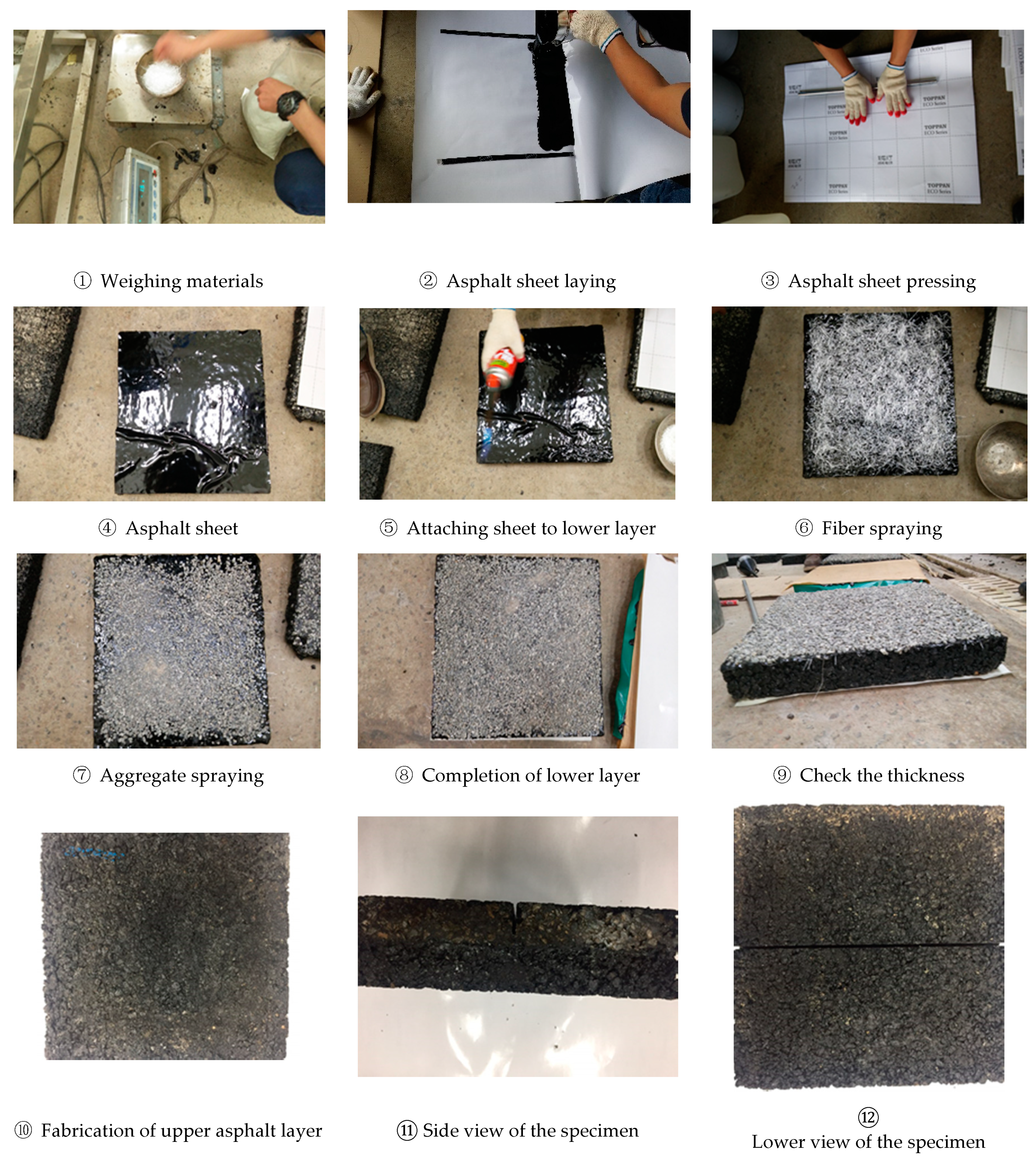
To evaluate the performance of the F-SAMI layer, according to the content of the asphalt binder and the use of aggregate, seven types of specimens were prepared, as shown in Table 2. In addition, after the preparation of the specimen was completed, the crack was simulated with a depth of 40 mm and a width of 10 mm in the center of the lower layer specimen, to simulate a reflection crack. The width and depth were determined in order to accelerate the occurrence of reflective cracks among the values mainly applied on expressways, according to Korean standards [2]. Figure 1 shows the whole process of specimen fabrication for the MMLS3 test. An F-SAMI or tack coating layer was installed on the lower layer and then sufficiently cured. After that, the top asphalt mixture was laid and compacted using a slab specimen compactor. It was concluded that there was no problem with attachment, because there was no detachment between the top and lower layers, even after the MMLS3 test.
Table 2.
Fiber-reinforced, stress-absorbing membrane interlayer (F-SAMI) composition.
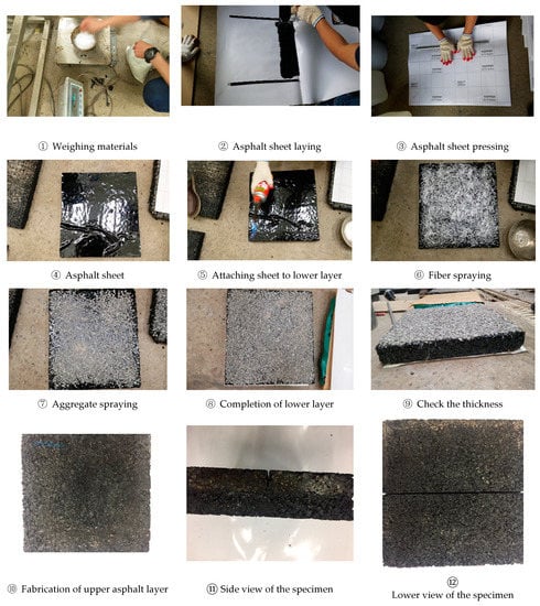
Figure 1.
Fabrication of model mobile load simulator 3 (MMLS3) specimen.
3.2. Experimental Condition for MMLS3 Test
The loading conditions of the MMLS3 test were a single wheel load of 2.7 kN and a speed of 10 km/h, and wandering was not used. Four tires with a diameter of 30 cm, which is 1/3 the size of a standard truck tire size, were installed in a row, and the tire pressure was maintained at 690 kPa. In addition, the test temperature was maintained at 20 °C by circulating water to the specimen bath for the entire experiment. Figure 2 shows the test view, in which the fabricated specimen is installed and the MMLS3 test equipment is fixed at the loading position.
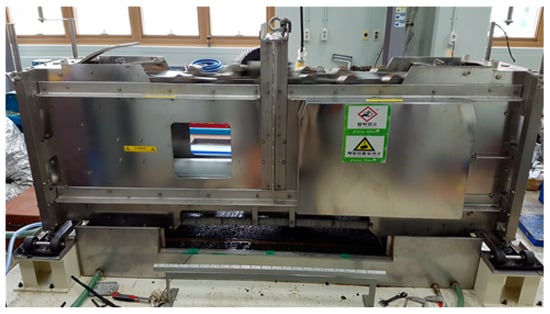
Figure 2.
MMLS3 test setup.
The existing MMLS3 test equipment is designed to perform a test by installing a test specimen on the top of a plastic base plate. However, in order to simulate the transition of the reflective crack, it is necessary to increase the tensile stress generated at the bottom of the test specimen under the load of MMLS3—so as shown in Figure 3, three rubber plates of 1 cm thickness were laid on the floor plate, and the test specimen was installed on the top. In addition, in order to secure sufficient tensile stress, the center of the rubber plate was cut out so that the specimen could be sufficiently bent when the MMLS3 load was applied.
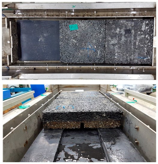
Figure 3.
Specimen installation.
3.3. MMLS3 Test Results
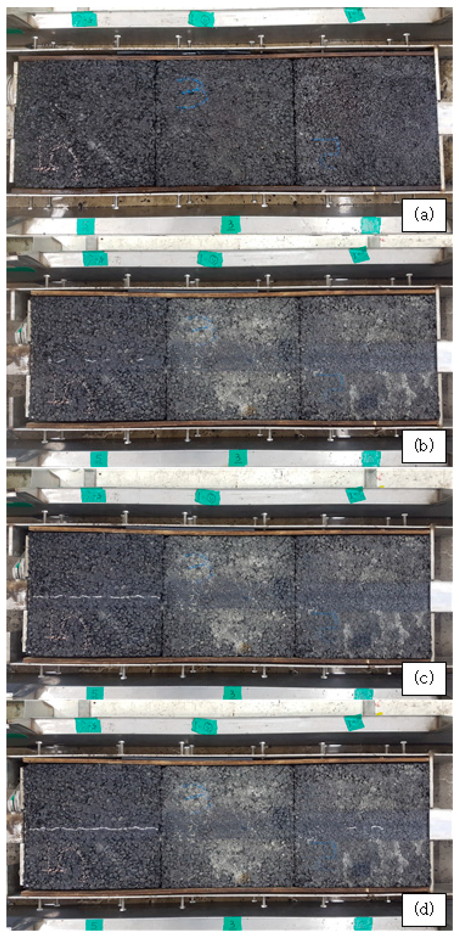
Figure 4 shows the occurrence and progress of reflective cracking in each specimen as the MMLS3 test proceeds. Figure 4a is the specimen top view before the MMLS3 load is applied, and Figure 4b shows that small cracks that occurred on the surface of specimen on the left side. Figure 4c shows that in the specimen on the left side, reflective cracks have occurred entirely on the surface, while in Figure 4d, the cracks occurred gradually in the specimen on the right side.
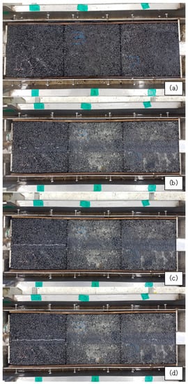
Figure 4.
Reflective crack occurrence and propagation. (a) specimen top view before the MMLS3 load is applied; (b) small cracks that occurred on the surface of specimen on the left side; (c) specimen on the left side, reflective cracks have occurred entirely on the surface; (d) the cracks occurred gradually in the specimen on the right side.
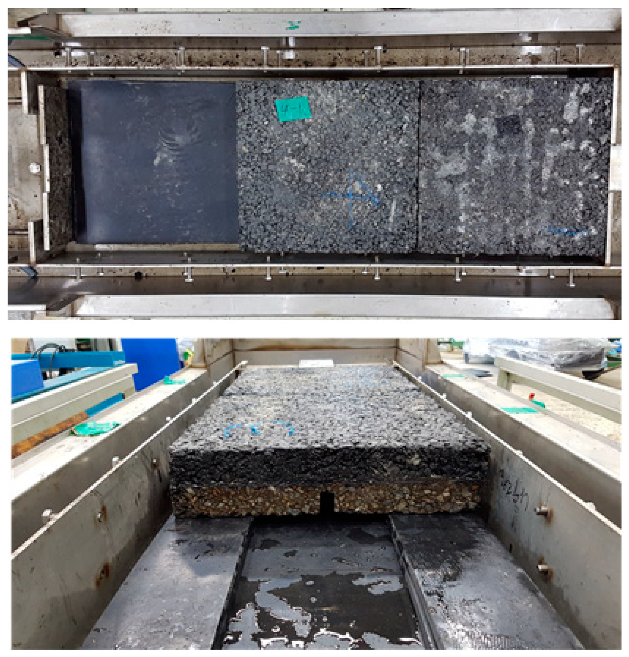
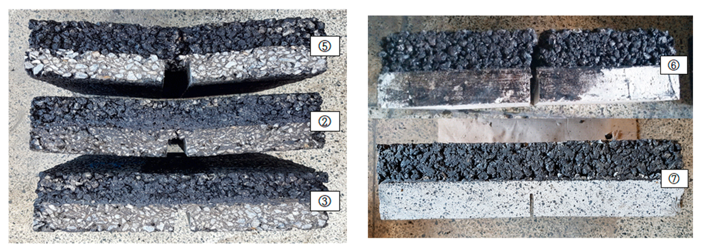
Figure 5 shows the side view of the specimen after the completion of the experiment. The MMLS3 experiment was conducted until the specimen was deflected due to reflection cracking and additional loading was impossible, as seen in specimen 5. From Figure 5, it was found that specimens 5 and 6, to which general tack coating was applied, were completely split due to the reflective cracking.

Figure 5.
Side view of specimens after the completion of the MMLS3 experiment.
Table 3 summarizes the number of loadings up to the point of reflective cracking in the upper part of the specimen, according to each specimen type, measured through the MMLS3 test. The number of loadings when reflective cracks completely occurred in the wheel path, using visual inspection, was taken as the failure criterion.
Table 3.
The number of loadings to failure for each specimen.
Regardless of the type of mixture in the lower layer, the specimens applied with the F-SAMI method showed significantly superior resistance to reflection cracking, compared to the specimens applied with the tack coating. In addition, in the F-SAMI method, the specimens containing aggregate showed greater resistance to reflection cracking than specimens containing no aggregate. As a result of comparing the effect of the asphalt content of the F-SAMI method, it was found that the effect of the contents did not show a specific trend. This is judged to be a result of the asphalt content applied in this test, being applied above a certain level that does not degrade the performance of the F-SAMI method.
4. Performance Evaluation Using Accelerated Pavement Testing (APT)
4.1. Accelerated Pavement Testing (APT) Facility
Field performance evaluation for composite pavement, to which the fiber-reinforced stress-relief layer (F-SAMI) method was applied, was conducted through accelerated pavement testing (APT) at the Korea Institute of Civil Engineering and Building Technology (KICT) in South Korea. This APT facility was built in 2014, and has been heavily used to evaluate the performance of various types of asphalt and concrete pavement [23]. The APT facility is shown in Figure 6, and the equipment name is HVS (Heavy Vehicle Simulator, manufactured by Dynatest, Gainesville, FL, United States). The APT equipment is covered by a temperature chamber to control the environmental effect. The APT is capable of applying a half-axle load of dual tires up to 12.5 tons with one-way travel. The maximum travel speed is 12 km/h, and it can apply lateral wandering within a 1000 mm range.
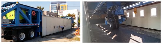
Figure 6.
Accelerated pavement testing (APT) facility.
4.2. Test Section Layout and Test Configuration
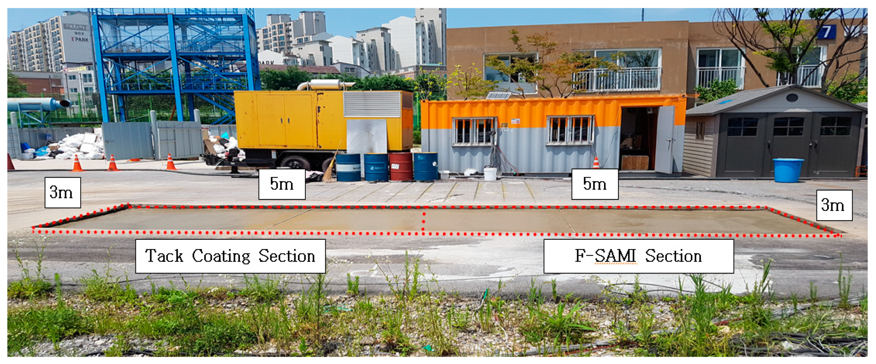
In order to evaluate the performance against the joint reflective cracking, an F-SAMI section (5 m × 3.0 m = 15 m2) and tack coating section (5 m × 3.0 m = 15 m2) were constructed at the APT facility in the KICT, as shown in Figure 7.
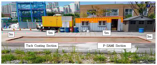
Figure 7.
APT test section.
A sub-base layer was constructed, with a thickness of 15 cm on the top of the compacted subgrade layer, and a concrete layer was constructed with a thickness of 15 cm on the top. Joints were constructed at a depth of 15 cm in the middle of each of the F-SAMI sections and the tack coating section. A 1 cm thick rubber plate was installed under the joint to increase the movement of the joint. On the top of the concrete layer, a PSMA surface layer was constructed with a thickness of 5 cm. Table 4 shows the materials used for test section.
Table 4.
Materials and grade for APT test section.
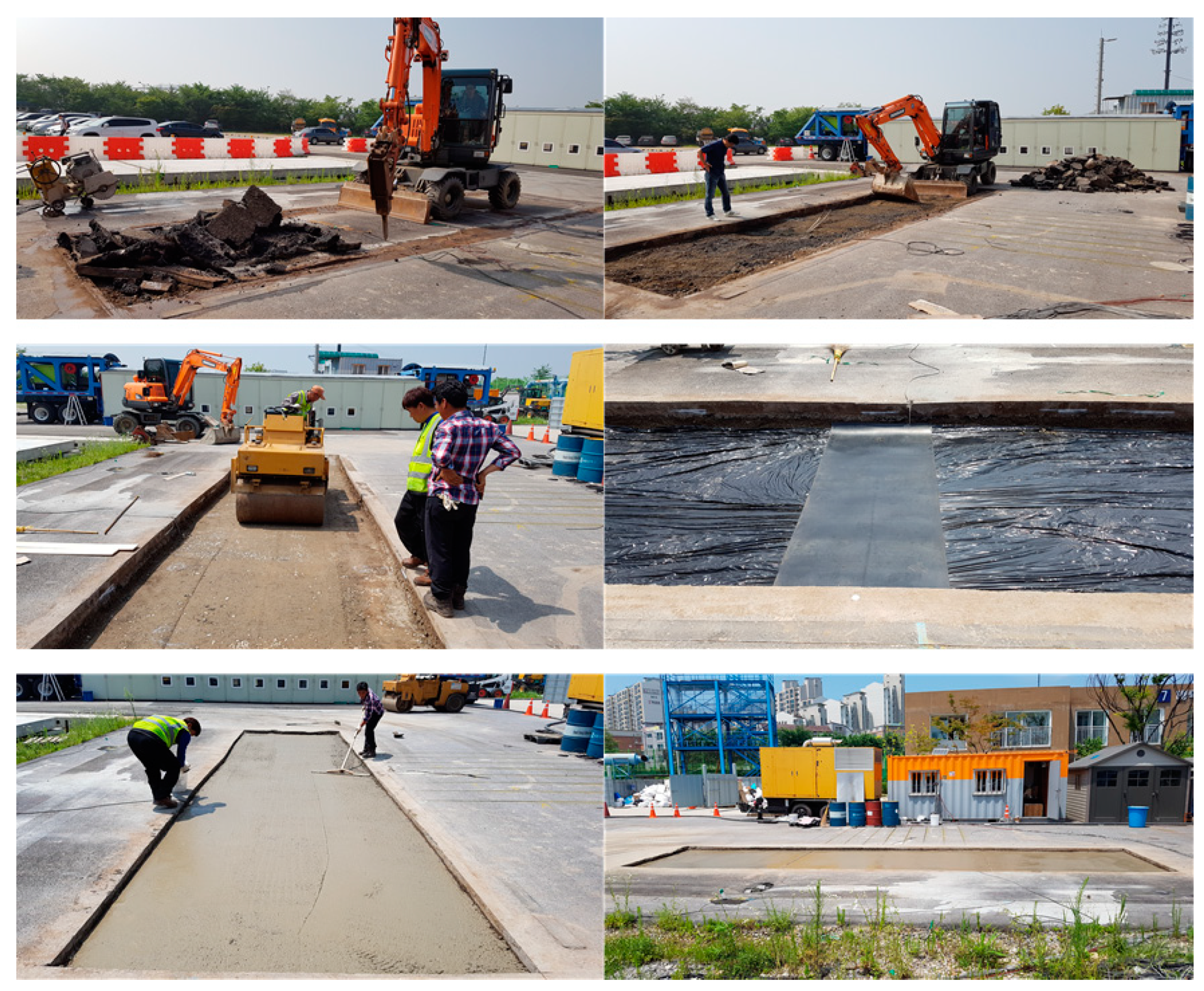
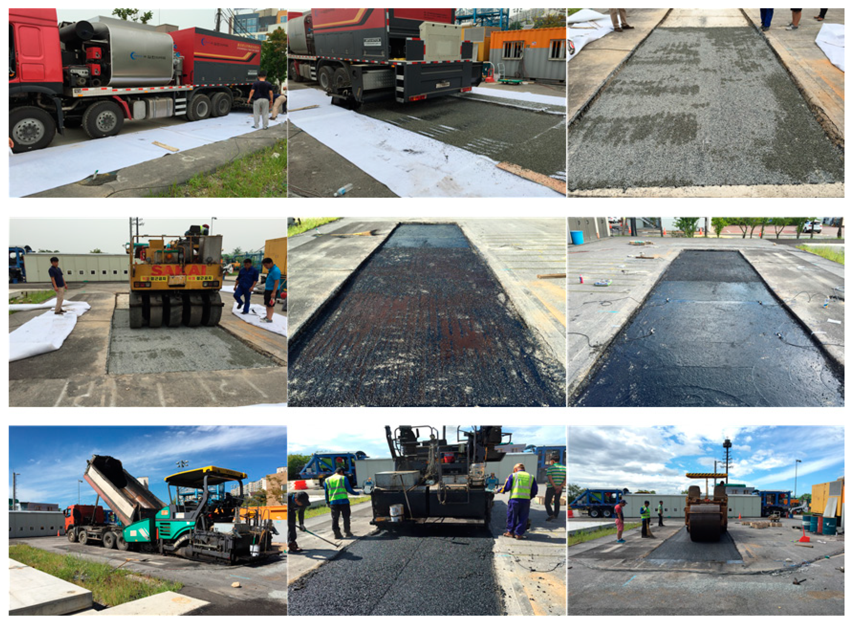
Figure 8 shows the construction of the sub-base and concrete base layer of the APT test section, and Figure 9 shows the construction of the stress relief layer and the surface layer.

Figure 8.
Construction for test section: lower layer.
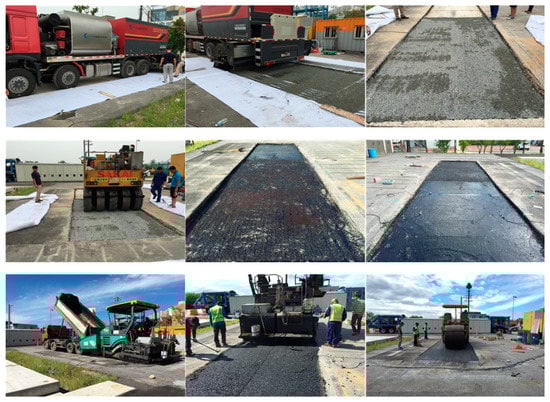
Figure 9.
Construction for test section: upper layer.
The APT test conditions applied to the F-SAMI, fiber-reinforced, stress-relief layer method test bed are as follows:
- ◦
- Load condition: dual-wheel load, 80 kN, 10 km/h, one-way loading
- ◦
- Load wandering: center-based, bidirectional 430 mm
- ◦
- Temperature condition: the surface temperature of the pavement is maintained at 20~25 °C using an air-conditioning system
- ◦
- Total number of loads: 200,000 load passes
Load wandering should be implemented to simulate the distribution of vehicle loads applied to the actual field pavement. In KICT APT, the wandering is controlled at 5 cm intervals through a sensor, so the number of load applications per load location can be applied similarly to the normal distribution. In addition, since the wandering position changes randomly when the vehicle moves in reality, the APT can be applied randomly for each period to simulate this. During the APT test, the pavement temperature is controlled by the heating and cooling system installed inside the APT and the chamber surrounding the APT, and is measured through a thermocouple.
4.3. Test Results of APT
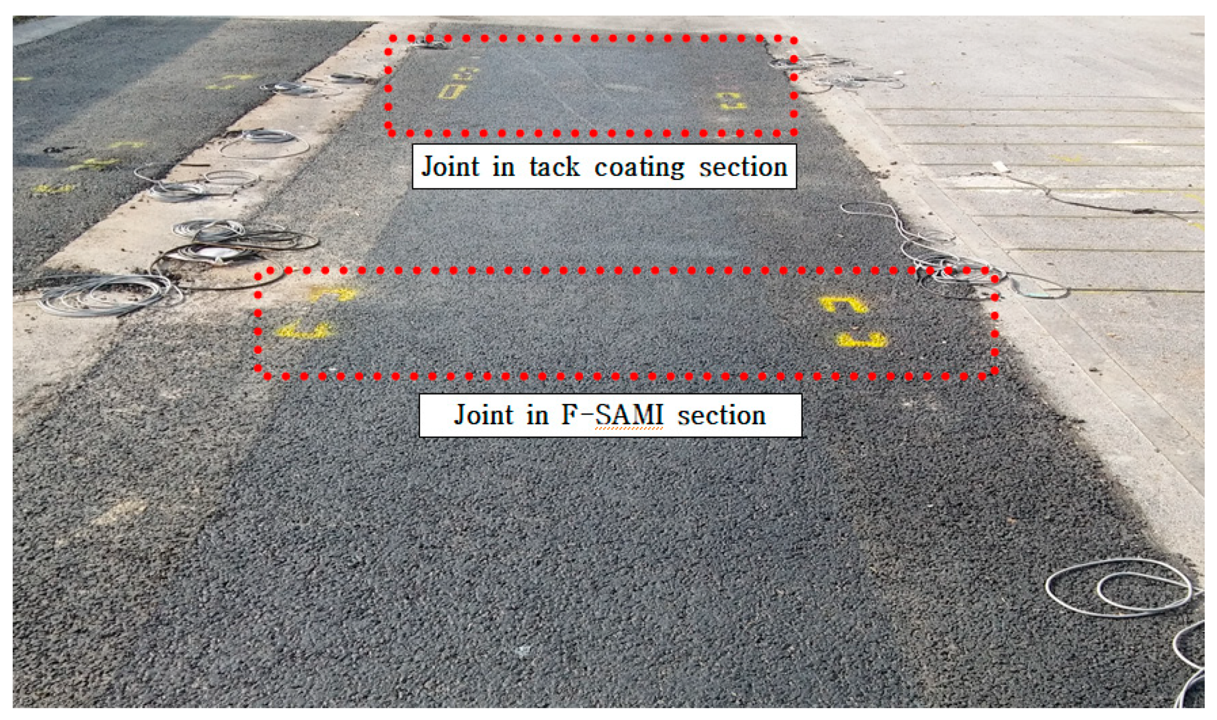
Figure 10 shows the section where cracks occurred at the joints of the test bed. Figure 11 shows the occurrence and progression of cracks in the F-SAMI section and the tack coating section, according to the APT load.
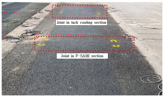
Figure 10.
Crack occurring area (top of the joint).
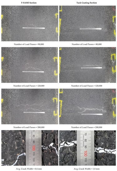
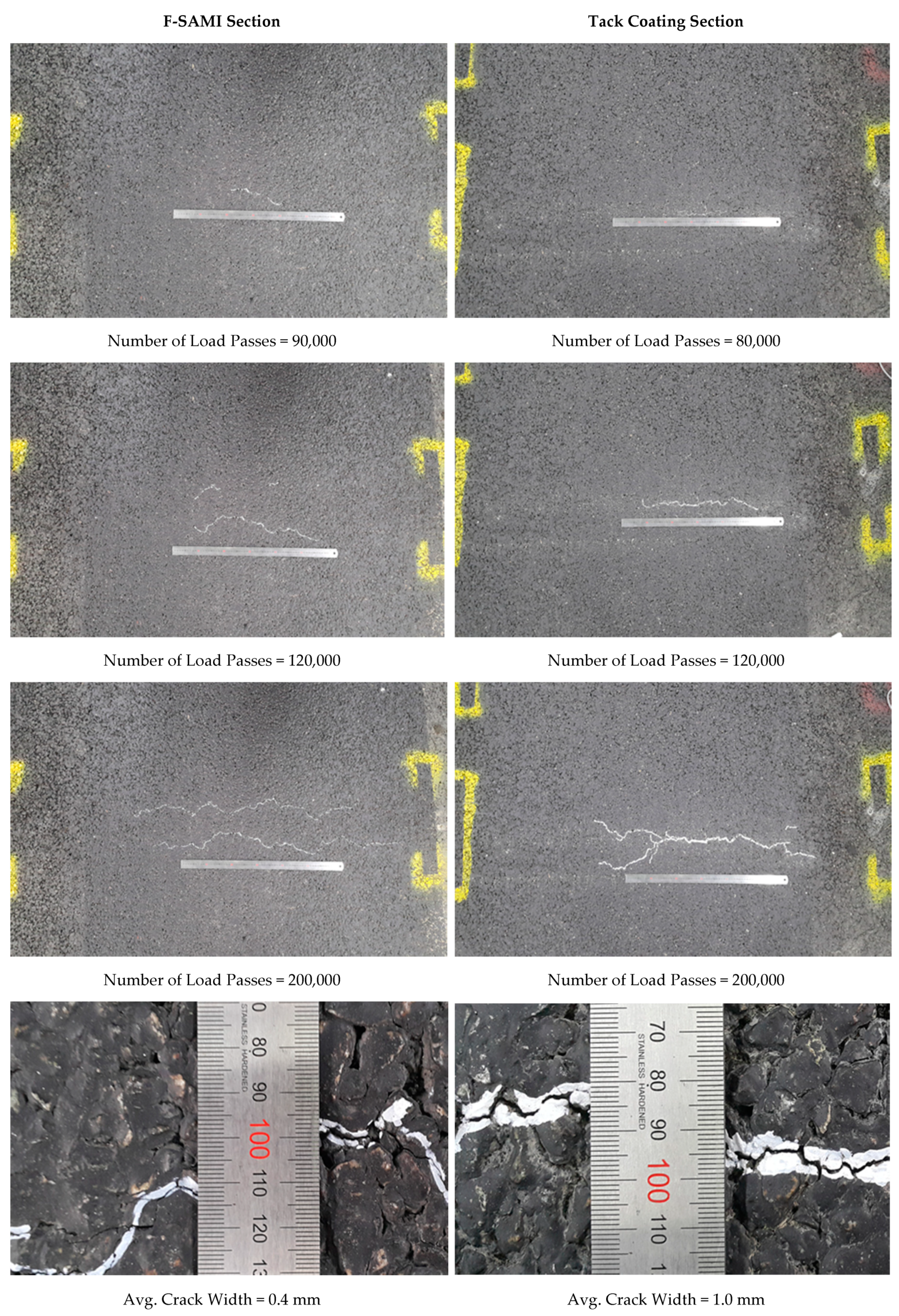
Figure 11.
Occurrence and progression of reflective cracks.
As a result of evaluating the cracks generated in each section, according to the APT loading, the initial cracks occurred at 80,000 load passes in the tack coating section and 90,000 load passes in the F-SAMI section. As a result of the crack propagation evaluation, the tack coating section progressed by cracking at the vertical upper part of the joint, whereas the F-SAMI section developed cracking at a location 7~8 cm away from the vertical upper part of the joint. The crack width of the tack coating section was 0.6~1.3 mm (average 1.0 mm), whereas the F-SAMI section was measured as 0.3~0.7 mm (average 0.4 mm).
At the beginning of APT loading, about 5.0 mm settling occurred in one part of the joint of the F-SAMI section. Since the movement of each slab is independent, due to the installation of the joints penetrating through the concrete base layer and the rubber plate under the joint part, this was estimated to be the settlement of the concrete slab due to the difference in bearing capacity of the sub-base layer. Nevertheless, the test was carried out as it was to consider the excessive reconstruction cost and to evaluate the performance of the F-SAMI layer under adverse conditions.
When applying the F-SAMI method, compared to the tack coating method, reflective cracks occurred about 10,000 load passes later. Reflective cracks in the F-SAMI section were dispersed, and the crack width was reduced by about half compared to those in the tack coating section. Therefore, in spite of the joint sag of the F-SAMI section, the reflective crack resistance of the F-SAMI method was evaluated to be superior to that of the tack coating method.
5. Conclusions
In this study, the reflective crack resistance of the asphalt overlay method using F-SAMI technology was evaluated using the small and large-scale pavement acceleration tests, and the following conclusions were drawn.
As a result of the evaluation of reflective crack resistance through an MMLS3 indoor test of a fiber-reinforced, stress-absorbing membrane interlayer (F-SAMI)-applied pavement specimen, it was found that the resistance to reflective cracking of the F-SAMI-applied specimen was superior to that of the specimen with tack coating between the two layers.
Regarding the effect of the F-SAMI composition ratio, it was found that the F-SAMI including aggregates had better resistance to reflective cracking, while the asphalt binder did not appear to have a clear trend with the application rate.
Based on evaluation of the reflective crack resistance of the F-SAMI-applied pavement structure through accelerated pavement testing (APT), when the F-SAMI method was applied the reflective crack occurred about 10,000 load passes later compared to the tack coating method. The crack length in the surface is similar for both sections, but the reflective crack in the F-SAMI section was dispersed, resulting in a decreasing crack width of more than 50%.
Therefore, the F-SAMI method is expected to increase the overall pavement life by suppressing the reflective cracks occurring from the joints or cracks in the lower layer if applied to the overlay construction on the old pavement.
Funding
This research was funded by Korea Institute of Civil Engineering and Building Technology (Project No. 2020-0449).
Conflicts of Interest
The author declares no conflict of interest.
References
- Eum, J.; Yang, S.; Jung, C. Methodology for Constraining Asphalt Concrete Overlay Against Reflection Cracking; Report No. 99-47-19; Korea Highway Corporation: Seongnam-si, Korea, 1999. [Google Scholar]
- Kwon, O.; Moon, K.; Kim, J.; Lee, J. A Study of Application Method of Asphalt Overlay on Aged Concrete Pavement; Report No. KECRI-2017-31-534.9607; Expressway & Transportation Research Institute: Dongtan-si, Korea, 2017. [Google Scholar]
- Seo, Y.C.; Lee, Y.M.; Kim, J.H.; Cho, N.H. Behavior and Resistance to the Reflection Crack of Composite Pavement with Waterproof Membrane. Int. J. Highway Eng. 2012, 14, 1–10. [Google Scholar]
- Hughes, C.S. Mitigation of Reflection Cracks in Flexible Pavements; Final Report No. VHTRC 78-R5; Virginia Highway and Transportation Research Council: Charlottesville, VA, USA, 1977. [Google Scholar]
- Mascunana, I. An Evaluation of Engineering Fabric in Pavement Rehabilitation; Final Report No. IHD-21; Illinois Department of Transportation: Springfield, IL, USA, 1981.
- McGhee, K.H. Control of Reflection Cracking in a Fabric-Reinforced Overlay on Jointed Portland Cement Concrete Pavement; Report No. VHTRC 83-R8; Virginia Highway and Transportation Research Council: Charlottesville, VA, USA, 1983. [Google Scholar]
- Barksdale, R.D. Fabrics in Asphalt Overlays and Pavement Maintenance; NCHRP Synthesis Report 171; National Cooperative Highway Research Program, National Research Council: Washington, DC, USA, 1991. [Google Scholar]
- Mukhtar, M.; Dempsey, B.J. Interlayer Stress Absorbing Composite (ISAC) for Mitigating Reflection Cracking in Asphalt Concrete Overlays; Final Report No. UILU-ENG-96-2006; Illinois Department of Transportation: Springfield, IL, USA, 1996.
- Carmichael, R.F.; Marienfeld, M.L. Synthesis and Literature Review of Nonwoven Paving Fabrics Performance in Overlays. Transp. Res. Rec. J. Transp. Res. Board. 1999, 1687, 112–124. [Google Scholar] [CrossRef]
- Bischoff, D. Evaluation of Strata® Reflective Crack Relief System; Final Report No. FEP-01-07; Wisconsin Department of Transportation: Madison, WI, USA, 2007.
- Ahlrich, R.C. Evaluation of Asphalt Rubber and Engineering Fabrics as Pavement Interlayers; Final Report No. GL-86-34; Army Corps of Engineers: Washington, DC, USA, 1986. [Google Scholar]
- Lytton, R.L. Use of Geotextiles for Reinforcement and Strain Relief in Asphaltic Concrete. Geotextiles and Geomembranes. J. Int. Geosynth. Soc. 1989, 8, 217–237. [Google Scholar]
- Epps, J.A. Synthesis of Highway Practice 198: Use of Recycled Rubber Tires in Highways. National Cooperative Highway Research Program (NCHRP); Transportation Research Record National Research Council: Washington, DC, USA, 1994. [Google Scholar]
- Amini, F. Potential Applications of Paving Fabrics to Reduce Reflective Cracking; Report No. MS-DOT-RD-05-174; Mississippi Department of Transportation: Jackson, MS, USA, 2005.
- Shatnawi, S. Maintenance Technical Advisory Guide; Volume I-Flexible Pavement Preservation Section Edition; State of California Department of Transportation: Sacramento, CA, USA, 2008.
- Bush, A.J.; Brooks, E.W. Geosynthetic Materials in Reflective Crack Prevention; Final Report No. SR 537; Oregon Department of Transportation Research Unit: Salem, OR, USA, 2007.
- Lorenz, V.M. New Mexico Study of Interlayers Used in Reflective Crack Control; Transportation Research Record. J. Transp. Res. Board. 1987, 1117, 94–103. [Google Scholar]
- Buttlar, W.G.; Dempsey, B.J.; Bozkurt, D. Evaluation of Reflective Crack Control Policy; Report No. ITRC FR 95/96-4; Illinois Transportation Research Center: Edwardsville, IL, USA, 1999. [Google Scholar]
- Vespa, J.W. An Evaluation of Interlayer Stress Absorbing Composite (ISAC) Reflective Crack Relief System; Final Report No. FHWA/IL/PRR 150; Illinois Department of Transportation: Springfield, IL, USA, 2005.
- Elseifi, M.; Bandaru, R. Cost Effective Prevention of Reflective Cracking of Composite Pavement; Final Report; Louisiana Department of Transportation: Hammond, LA, USA, 2011.
- Brown, S.F.; Brunton, J.M.; Hughes, D.A.B.; Brodrick, B.V. Polymer Grid Reinforcement of Asphalt. Assoc. Asph. Paving Technol. 1985, 54, 18–44. [Google Scholar]
- Gilchrist, A.J.T. Control of reflection cracking in pavements by the installation of polymer geogrids. In Proceedings of the Conference on Reflective Cracking in Pavements, Liege, Belgium, 3–6 October 1994; pp. 350–357. [Google Scholar]
- Park, H.M.; Kim, Y.T.; Choi, J.Y.; Kim, K.H. A Preliminary Study for Assessing the Risk of Road Collapse Using Accelerated Pavement Testing. Int. J. Highway Eng. 2016, 18, 57–62. [Google Scholar] [CrossRef]


Publisher’s Note: MDPI stays neutral with regard to jurisdictional claims in published maps and institutional affiliations. |
© 2020 by the author. Licensee MDPI, Basel, Switzerland. This article is an open access article distributed under the terms and conditions of the Creative Commons Attribution (CC BY) license (http://creativecommons.org/licenses/by/4.0/).