Featured Application
The 6-wheel general purpose autonomous mobile robot can be used for various material transport tasks. Fully autonomous disinfection of large areas is provided with optional UV+ germicide add-on.
Abstract
This paper describes the development of Phollower—an autonomous mobile robot intended to perform various logistical tasks in both industrial and civil environments. Phollower is equipped with the latest types of industrial components and sensors. It also employs advanced embedded navigation and localization software to create its own virtual maps and thereby to navigate autonomously within the mapped area. The whole development process has been focused on building a device that meets European safety standards. Phollower is a universal mobile platform that can be quickly expanded with specialized add-ons. A germicidal add-on for disinfection of indoor areas using UV-C light is described as a technology that helps to battle with the ongoing COVID-19 pandemic crisis. The hardware topology combined with the proposed open Programmable Logic Controller (PLC) code and open-Powerlink communication bus creates a unique and easily extendable robot platform.
1. Introduction
Industry 4.0 means not only changes in the traditional industrial environment but also changes in everyday life. E-shops try to offer the most comprehensive range of goods available in stock. Producers in the automotive industry aim to adjust ever more to the customer’s individual needs and expectations. In healthcare, there are strong efforts to reduce the routine work of healthcare professionals to enable them to focus more on nursing the sick instead. Based on all the examples mentioned above, there is a high potential for using intelligent robots that can perform not only repetitive tasks but also collaborate with humans and for the robot to be able to change its workload quickly and efficiently. In this regard, automated guided vehicles (AGVs) until now have been number one in the field of logistics. Single-purpose mobile robots have been used to transfer material from point A to point B using navigation lines, mainly in industrial halls. While Industry 4.0 is considered to be a current standard in industrial technologies, AGVs are frequently replaced by a new type of mobile logistics robots, known as autonomous mobile robots (AMRs). In comparison to AGVs, this new technology enables faster and more efficient deployment in operation; it is ‘more-intelligent’, and therefore, it cooperates better with the system environment and gives the user the option to assign tasks efficiently and promptly.
The contribution of this paper consists of the following. It presents the development of an AMR named Phollower, whose development process was founded on previous experience gained while developing its successful predecessor—Pathfinder [1]. While Pathfinder was designed for operation solely in the health service environment, the new generation, Phollower, is primarily focused on being a universal autonomous mobile robot that meets European safety standards. Phollower has been built exclusively from industrial components.
The development of Phollower was focused on the ease of use and the ability of solving different types of logistics tasks. What makes it different to other available solutions on the market is the use of various interchangeable add-ons and an open access software approach. Our aims were robust mechanical design, sufficient space for material transport, collision avoidance features, and a simple user interface. Phollower can be used as an autonomously working self-employed machine whose tasks are set up by web interface. Even more, API interfaces and operation of several Phollower robots from the central control system is possible. It has an intuitive and user-friendly web interface that guides users with help texts providing detailed operating instructions.
While many solutions of today’s AMRs are based on Robotic Operation System (ROS), there are also other frameworks that can be applied, such as Google ROBEL or Apollo BAIDU to mention a few. It should be stressed that by utilizing ROS in general AMR solution, a strong technological dependence and one-track ROS orientation arises. To use different approach, a part of Phollower technology is API as a set of standardized and described commands, events, status and sensor messages, all of which enable full control of Phollower. The API is based on Python language that is platform independent (Linux or Windows). New features can be added using an open Programmable Logic Controller (PLC) library that enables safety customization to meet all requirements of manufacturing processes. This paper provides a detailed overview of all the features of Phollower’s technology.
2. Related Work
Phollower has been designed and developed as an AMR for the industrial and civil indoor environments. In operation, such a complicated device is challenged by adverse and unspecified situations that may result in hazardous behavior [2]. It is indisputable that safety is a crucial characteristic here. Therefore, from the early beginning, all the safety requirements for machinery had to be applied in the whole development process in accordance with Directive 2006/42/EC of the European Parliament and of the Council of Europe [3,4]. This directive includes a set of standards and must be fulfilled by any machinery intended to be placed on the European market. In the case of mobile platforms, compliance with the following standards is required:
- EN ISO 12100: General principles for design,
- EN 60204-1: Safety of machinery, electrical equipment,
- EN 1175-1+A1: Safety of industrial trucks, requirement for battery powered trucks, and
- EN 1525: Driverless trucks and their systems.
Safety must be quantified, and it must be shown with confidence that the vehicle is safe. Several approaches for vehicle safety validation can be found in the literature:
- (a)
- worst-case scenarios, using the assumption that less demanding situations are handled if the worst-case is handled. This is done by directed testing, and it is the most straightforward and yet valid approach;
- (b)
- to use models to verify that different parts of the AMR work together safely. This requires valid models for everything that can affect the system, which is time-consuming and not always applicable;
- (c)
- to use field tests and from their results show statistically the vehicle is safe enough, where the Extreme Value Theory statistic method can be used [5] with a high validity and lower amount of data required.
Three different safety concepts were proposed and discussed in [6] to design a safe environment for indoor AMRs. They include the safety ring for reliable object detection, safe navigation, and environmental awareness. However, not all proposed concepts for MiR100 [6] have been implemented, and their mutual evaluation is still missing. For [7], safe and robust movement in a complex 3D environment, scenarios were obtained by the combination of variable step-size rapidly exploring random-tree (RRT) method for global path planning together with the local planner for safe path optimization. A solution for the quantitative derivation of the collision risk with the speed control strategies for safe indoor navigation was presented in [8]. The safety speed margin and minimum time for path optimization were chosen as the two criteria by which safety was guaranteed. Safe and rapid AMR navigation in greenhouses was proposed in [9].
A modification of differential evolution optimization algorithm was introduced to find optimal and safe navigation points to avoid damage of agricultural products. An exciting safety approach is the detection of “smartphone zombies” that was shown in [10] using Light Detection and Ranging (LiDAR) point cloud streams and an enhanced segmentation-based method. It enables the AMR to recognize and avoid pedestrians with smartphones and thereby navigate safely. Potential safety and security features during the design level phase of AMR development were studied in [11], but the presented solutions suffer from low latency in communication systems. Commercial AMRs with comparable technology to Phollower [12,13,14,15,16] mostly use safety LiDAR system with probabilistic algorithms.
3. Mechanical Design
Wheeled mechanisms are the most favorable for mobile robots indoors because of their mechanical simplicity and high efficiency [17,18,19]. Phollower was constructed as a 6-wheel robot (see Figure 1), with the two center wheels powered. These are placed on a rocker arm along with the front and rear supporting wheels. Such a balanced system enables the robot to overcome some uneven or hilly terrain of up to 5 gradient, as shown in Figure 2. Phollower’s built-in balance system consists of the following:
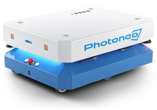
Figure 1.
An overview of Phollower’s base construction.
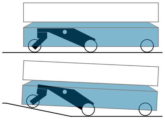
Figure 2.
Phollower’s balance system to overcome uneven terrain.
- main rocker arm,
- front supporting wheel,
- bearing housing used to connect the electric drive to the powered wheel,
- socket in which the safety encoder is being placed, and
- system of two gear wheels to ensure the transmission of the turning motion of the main powered wheel to the safety encoder axis.
The electric drive and powered wheel mounting must be designed to be strong enough to carry the weight of one-sixth of the total weight consisting of the robot’s weight along with the carried load. Therefore, the connection of drive and wheel is made via a bearing housing designed for this purpose. This type of mechanical design allows Phollower to carry a heavier load without any risk of damaging the drive axle.
The robot’s load-bearing structure is built of a welded steel beam construction on which all the mechanical and electric components of the robot are mounted. The total load capacity was designed for a direct load of 100 kg (see Table 1). All wheels are protected by aluminum covers on the sides, which are a partly protective cover. Only the necessary parts remain uncovered.

Table 1.
Basic mechanical parameters of Phollower.
Both center wheels are independent and driven by servomotors. Each servomotor has (in addition to its own resolver) one more safety encoder that evaluates an actual speed value for the needs of the safety ring. The odometry is calculated by resolvers and combined with the odometry obtained from laser scanners. This data fusion increases navigation accuracy; furthermore, drawbacks of both methods are mutually eliminated. For example, wheel odometry is problematic during rotation movement, whereas scanners can handle it smoothly. Conversely, scanners fail on long corridors that do not contain contours. There, the output patterns of scanners do not change, but wheel odometry can precisely detect a real robot movement.
4. Electrical Design
The position of the built-in electrical components was adjusted to the size of the space remaining inside the construction (see Figure 3). Lead-acid batteries are mounted between the parts of the rocker arm balance system. Placing the heavy batteries near the center of gravity improves the stability of the chassis, especially when it is fully loaded. A Programmable Logic Controller (PLC) with integrated programmable safety cards was installed and used to control the drives and also to process the signals. Safety cards evaluate the signals coming from the safety sensors and switch the STO input of the drive inverter, if necessary.
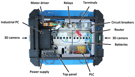
Figure 3.
Positions of built-in electrical components.
An industrial computer with the Linux operating system was used for calculating and processing the trajectory, as well as for navigation. Fast and reliable communication between the PLC and the industrial computer are provided by the open-Powerlink industrial bus, while openPowerlink Stack is used for the Linux part. The interconnections of all components are shown in Figure 4. This technology was developed in [1] where more detailed information is provided.
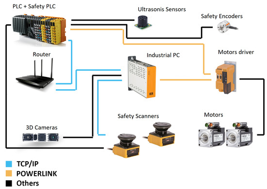
Figure 4.
Interconnections between all electrical components in Phollower.
5. Safety
5.1. Laser Scanner Placement
In the past, human safety was one of the main concerns that prevented autonomous robots from performing certain specific tasks (e.g., physical human–robot interaction). Basic human safety is ensured here using a pair of Hokuyo UAM-05LP-301 safety laser scanners, placed at opposite corners of the robot. However, to achieve human protection all around, the construction of Phollower had to be tailored to not have any part or a component interfering with the active measuring field of each laser scanner. The key requirement is to ensure the widest possible field of the scanners vision, ideally to cover all 360 around the robot and thereby operate safely and navigate precisely. This was achieved by narrowing the cover plates in the section that corresponds to the active measuring field of the scanners, as shown in Figure 5. In this way, a 360 continuous protective safety field was secured without any blind angles. A similar approach was used in [6]. Both scanners are fixed directly to the robot’s structure and protected by the top cover plate, while only the scanning part of the scanner remains unprotected.
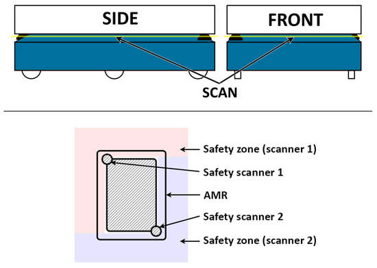
Figure 5.
The measuring slot and placement of safety zone scanners.
Safety scanners enable to set up the safety zone up to 5 m and the warning zone up to 20 m. These scanners are primarily dedicated for AGV applications, and a safety zone can be recalculated in real time based on data obtained from digital inputs and based on data from safety encoders. Safety scanners meet the requirements of PLd Cathegory 3 and SIL 2 standards.
5.2. Safety Zones
The safety requirements of Phollower are considered to include both passive and active machinery safety. Protective metal covers ensure passive safety. Active safety consists of electrical drives with their safety codecs, a safety PLC that evaluates the direction and speed of the robot according to signals from safety encoders, and safety scanners that are used for monitoring the area in front of and behind the machinery (i.e., the safety zone). Note that it is essential to use a safety chain consisting of safety encoders, safety PLC, and safety laser scanners.
It must be stressed that the size and the shape of the safety zone vary with the direction of movement and the actual speed of the robot. Therefore, its size and shape need to be thoroughly calculated, implemented, and experimentally verified. The setup and the braking distance protocol was created for the safety scanners. It characterizes the relationship of braking distance depending on the direction of movement, actual speed, and the shape and size of the safety zone. These parameters were calculated for a fully loaded vehicle with a safety factor of 1.2 (120% weight overload).
Safety LiDAR operation can be disrupted by a random reflection of shiny objects, such as a glass or mirror. This is detected by Phollower as a “false” safety zone disruption, and it is followed by an immediate stop. These glints are unpredictable, so this routine has been adopted and safety stop is executed every time the glint is detected. There is one more additional 3D camera-based algorithm that detects obstacles above or below the LiDAR scan height range. Used 3D cameras do not have safety certification, but a camera certification is not required by the safety standard. This additional algorithm records a point cloud in front of the robot in the longitudinal direction, and if an obstacle is detected in the point cloud, the robot will decelerate and stop to avoid collision. This protection is applied across the entire width of the robot’s body and detects obstacles 5 cm above the floor.
5.3. Braking Distance
The calculation of the robot’s braking distance is done in two steps. Firstly, a deceleration value is obtained from the braking force (in Table 1) and friction force :
The value of is then used to determine braking distance as follows. A momentum p of the vehicle with the total mass m moving with speed v is defined as:
The braking force over the time must be applied to change the momentum to zero:
Therefore, a braking time needed to completely stop the vehicle from its initial speed is
Finally, a braking distance is calculated as
The value of braking distance is needed for calculation of the size of safety zone S, given by EN ISO 13855 and EN IEC 62046 standards together with the manufacturer’s recommended setting of the safety laser scanner [20]. The following formula was used that is specifically related to the safety zone S of scanners placed on the mobile platform:
Parameter is determined in compliance with the manufacturer’s recommendation. It increases the safety zone as the ground clearance of the vehicle increases (see Figure 6). Table 2 contains all values needed for the calculation of safety zone in Equation (8).
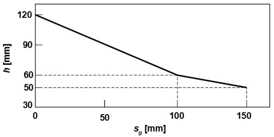
Figure 6.
Parameter as a function of vehicle ground clearance h.
Table 2.
Parameters for calculation of safety zone size from Equation (8).
5.4. Experimental Verification of Safety Zone
Experimental verification consisted of a series of measurements of the actual braking distance at different speeds of the robot with a total weight of 120 kg. During the experiment, various types of objects were used as an obstacle. Each of them simulated parts of the human body in different positions. Specifically, a standing child simulation, a standing adult simulation, a lying adult simulation, and a reliable obstacle simulation were required (Figure 7). The comparison of the theoretical and experimental values of the braking distance is shown in Table 3.
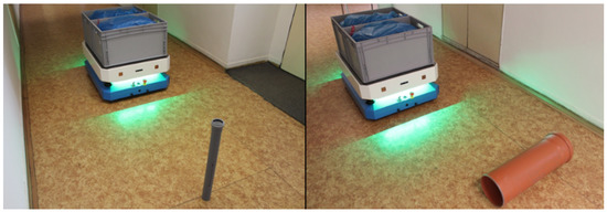
Figure 7.
Experimental verification of the braking distance value.
Table 3.
Results of breaking distance calculated vs. measured values.
6. Navigation and Interface
6.1. Position in the Map
The navigation system is based on a combination of the mechanical wheel rolling data and data from a pair of safety scanners. The output signal from scanners consists of an array of points representing the measured distance from the obstacles located in the nearby environment. The safety scanner provides the measurement range of 0 to 270 with an incremental step of 0.25. All these points are transmitted in the form of polar coordinates. The safety scanners output data are shown in Figure 8.
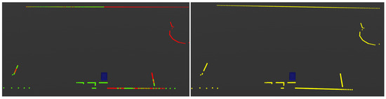
Figure 8.
The signals from both front and rear scanner (left), and the final output 360 environment scan (right).
The first step in the safety scanner data processing is represented by the conversion of each output signal into a common polar coordinate system. The conversion results in 1080 points acquired via the front scanner and another 1080 points acquired with the rear scanner. However, there are overlapping parts in the field of view of both scanners, which can be observed in Figure 8 (left). The final output signal from both scanners has to be merged, in the range from 0 to 360, with an incremental step of 0.25. The final data consist of 1440 points needed to create a virtual 360 laser scan of the environment, Figure 8 (right). B&R PCL library [21] is used for the calculation of the virtual total angle laser scan. It transforms individual points into a point cloud object. The final laser scan with the required parameters is regenerated from that point cloud.
The calculation of the robot’s location within the virtual map is provided using Andrea Censi’s Canonical Scan Matcher algorithm [22] and Monte Carlo localization [23]. Andrea Censi’s Canonical Scan Matcher algorithm is based on the fusion of odometry from the wheels, together with the changes in the contours of the laser scan.
The output signal coming from the laser odometry always represents only a delta offset from the previous position, which leads to integration error in the absolute position due to delta offset integration. Monte Carlo localization is used for elimination of the integration offset. It compares the shape of the current laser scan and the virtual environment map, and, based on the comparison of the actual information of what the robot sees and the information from the map of what the robot should see, the integration error is suppressed.
Global positioning accuracy has been verified by a set of measurements. Phollower was equipped with a chessboard pattern on its top and then navigated from randomly chosen locations to the certain measurement station. An area above this station was monitored by camera, and precise position ( coordinates) was obtained by comparing the chessboard position with camera data each time the robot stopped. Evaluation of data obtained by this measurement showed average positioning accuracy error less than 1 cm.
6.2. Predefined Trajectories
The fundamental function of each AMR is to get from the current position within the environment to a user-determined position. Phollower provides two different approaches. Each of them is suitable for a different type of environment. However, the choice of the approach to be used is made solely by the user.
The predefined trajectory is usually suitable for an industrial environment, where fixed rules for the movement of the motorized industrial systems are applied. This type of use is mainly represented as operations with material supplies needed for production lines. In such cases, the specific paths along which these systems can move and perform are precisely defined and marked. A mechanical barrier often separates these paths from the rest of the environment. This version with predefined trajectories also represents a virtual path (virtual magnetic tape for AGV systems) within a virtual map. All preset stops are interconnected by a strictly defined trajectory. Altogether it creates a route network around which the robot can move. For route calculation purposes, Dijkstra’s algorithm is used [24].
Figure 9 shows the route network together with the actual trajectory of the robot. A specialized web interface for the visualization of the map, stops, and trajectory was implemented for this type of operation. It gives the user the option to select individual targets and control the course of an autonomous movement. This type of navigation comes with the disadvantage that the robot is not able to dynamically bypass obstacles on the path. In this mode, Phollower only sends a notification about the barrier on the route to a nearby responsible human operator.
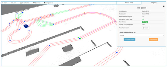
Figure 9.
An example of a predefined trajectory operation.
6.3. Dynamic Trajectories
The opposite concept is represented by dynamic trajectories shown in Figure 10. In this case, the user only defines some individual stops within the environment. After that, Phollower performs the route calculation within the virtual map between the stations using the A star algorithm [25]. This type of trajectory determination is suitable for environments where it is not strictly defined where the robot can or cannot move. As dynamic trajectories are executed cyclically, it is also suitable in environments where many moving obstacles occur randomly. Hospitals and shopping malls are potential environments with demanding requirements for which dynamic trajectories are particularly suitable. For both operation modes, the execution of the chosen path is a task for the position controller. Phollower uses the well-known pure pursuit algorithm iterated in every cycle, which means continual updating of the actual vehicle position and a new look-ahead point determination. Detailed information about the implementation of the pure-pursuit algorithm can be found in [1].
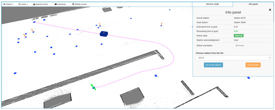
Figure 10.
An example of a dynamic trajectory operation.
7. Addons and Extensions
7.1. Phollower Extendability
One of the most important and innovative contributions of Phollower technology is the possibility to plug in various types of functional extensions, known as “add-ons”. The prerequisite has been prepared using the open-Powerlink communication bus [26], which enables the design and further connection of any compatible devices to the existing system. However, to be able to control the add-ons and to process their data through the master PLC, it is necessary to add new service routines directly to the PLC. Most commercial devices do not make their source codes available as open-source, and there is no possibility for the user to change them. This is why Phollower is designed otherwise.
A pre-created project for the Automation Studio software was created and made available, in which the basic functionality of Phollower is created as a binary library. This concept provides a solution that allows users to open the system and to add their own devices and software packages. Furthermore, this concept keeps the intellectual property of the essential service software protected. On the other hand, it still makes it possible to expand the system freely. This solution only underlines the system’s versatility and the ease of how Phollower adapts to the specific user requirements.
The option to expand the system with the various types of add-ons based on the software solution mentioned above requires hardware preparation. In the case of Phollower, this is ensured by the set of connectors placed on the top of the cover plate (detailed in Figure 11). These connectors provide the power input, connection to the LAN Ethernet, connection to the open-Powerlink bus, four preset digital inputs, and another four preset digital outputs. These digital I/Os can be used immediately in cooperation with the add-ons shown in Figure 12. The combination of the available interfaces creates a versatile system able to be expanded with a set of additional I/O cards, with drivers for small or mid-size electrical drives, with various display units or additional safety features.

Figure 11.
Freely available Phollower interfaces.
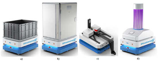
Figure 12.
Various add-ons for Phollower: (a) simple transport, (b) locked box transport, (c) towing add-on, and (d) Phollower UV+ germicide add-on.
Figure 12 shows selected add-ons that have been already designed and tested with Phollower. In Figure 12a an essential passive add-on for transportation of various types of materials is shown. The add-on in Figure 12b serves as a safe way to transport material in a locked box. The add-on in Figure 12c was developed for the autonomous towing of trucks. In cooperation with the safety encoder, the towing add-on can ensure a safety tracking gap function between the robot and a truck.
7.2. Germicide Add-On
COVID-19, the disease caused by the novel coronavirus, has created a global lockdown. People located in contaminated areas are putting themselves at considerable potential risk. To reduce human contact in these affected indoor and outdoor areas, disinfecting robots are being developed [27]. One of the ways to eliminate the virus without chemicals is to use UV-C light. Automatically controlled non-contact ultraviolet surface disinfection robots can be used because COVID-19 also spreads via contaminated surfaces [28]. This disinfection procedure will inactivate the coronavirus without any further modification.
UV-based disinfection robots, such as UVD Robot [29], Violet [30], Connor [31], or Wellwit WDR01C [32], are usually made as single-purpose devices. Moreover, their simpler versions must be operated manually. In contrast, the disinfection ability of Phollower is purely designed as an optional add-on. We consider this add-on conception one of the most important features of Phollower.
Phollower UV+ (see Figure 12d) is the special add-on with germicidal radiators designed to disinfect spaces using UV light in exposed environments such as hospitals. It consists of four 1500 mm long germicidal tubes with 75W power, placed vertically opposite each other to the central supporting structure. A warning beacon is placed at the top of the supporting structure. It lights-up 15 s before the radiator starts to emit light to warn the operator and surrounding humans to leave the place and not to enter during disinfection.
As the primary objective, safety functions have also been implemented in this add-on. The four widescreen cameras with algorithms for human detection have been placed on the top of the central supporting structure (under the beacon). If a human body happens to be detected during disinfection, the germicidal radiators will turn-off to ensure safety and to prevent any human being exposed to UV radiation.
There are two disinfection modes for the germicidal add-on:
- (a)
- the UV-C radiator is activated at the stations only, during the transfer to the next station, light emission is deactivated;
- (b)
- the UV-C radiator is activated both at the stations and during movement, the user can adjust both the times spent on the station and the movement speed from 0.01 m/s to maximum speed.
The operating period per one battery charge is around 4 h of disinfection time using a standard monitoring device [33]. It means that several rooms can be decontaminated. Note, that it heavily depends on the spatial arrangement of rooms and resulting movement trajectories.
7.3. Calculation of Maximum Speed for Radiant Exposure
Let P be the radiant power of one germicide tube. Note that radiation is possible only in the horizontal direction. Irradiance (radiant flux received by a surface per unit area) from one tube is based on the cylinder surface S:
where h is the tube height (m) and r is the distance (m) between the germicide tube and a nearby point that must be exposed to UVC (a red point in Figure 13).
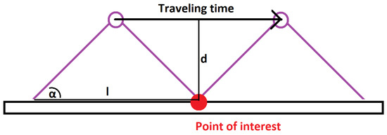
Figure 13.
The geometry of robot movement during disinfection.
The longer the point is exposed to given irradiation, the more viruses will be killed. This is given by radiant exposure (J/m). The value of radiant exposure = 3500 Ws/cm is needed to kill 99% of the covid viruses [34]. Note that speed of the moving robot must be adjusted to ensure desired radiant exposure.
In Figure 13, the red point is a place along the trajectory that needs to be disinfected, purple circles are two germicide tubes, and l is the distance traveled by the robot during which a point to be disinfected is exposed to UVC:
The time needed to reach value = 3500 Ws/cm is calculated by
where is the the value of the equivalent power needed to ensure 3500 Ws/cm, and P is a function of distance d. Table 4 shows examples of maximum speed
of the robot for effective disinfection. The maximum speed for each segment of robot trajectory is calculated in order to ensure desired radiant exposure of given surfaces along path. It can be concluded that predefined trajectories of Phollower with this add-on will ensure safe and effective disinfection. However, the proposed germicide add-on has one disadvantage. Germicide tubes are placed vertically, and therefore floors are less exposed to UV+ radiation. The highest point of radiation is at the height of an average adult’s shoulder. Disinfection of surfaces and objects in reachable distance of a human’s hand is a primary objective here, as these surfaces can be tapped or touched by hands and infected by viruses. This disadvantage can be solved by using one more horizontally placed tube in the front part of Phollower. This will be offered as another add-on functionality.
Table 4.
Examples of maximum speed for a given surface distance.
The power consumption of UV+ add-on is 300 W, which reduces the total operating time of the robot by around 40%. A full charge of the battery takes 75 min and enables several disinfections per night. However, the UV+ add-on operates with the same battery as the remaining part of the robot to not increase production costs. Moreover, if the UV+ add-on was powered by its own separate battery and both batteries were charged form the same charger, a balance circuit would have been required to charge unevenly discharged batteries.
8. Conclusions
This paper has described the development of Phollower, a general-purpose 6-wheel autonomous mobile robot with center axle drive. Using the latest B&R Industrial Automation hardware components and the most recent software stacks and libraries for autonomous localization, navigation, and mapping, we have developed a platform that is versatile and easily modifiable. The development process has been targeted at two goals: meeting the safety requirements of European certification bodies and designing a universal robot. The coronavirus epidemic has put a spotlight on automated disinfecting technology as a potentially vital tool to protect humans. Instead of manual disinfection, which increases the risk of exposure of cleaning personnel, autonomous mobile robots could lead to cost-effective, fast, and effective disinfection. In light of these circumstances, the versatility and flexibility of Phollower could be a great benefit. Future development will be focused on raising its load capabilities and on extending the several add-ons provided. The backbone of solutions will still be tied to open-PLC and open-Powerlink technologies.
Author Contributions
Conceptualization, J.B.; methodology, J.B. and P.T.; software, J.B., L.H. and S.A.; validation, L.H.; formal analysis, J.B.; investigation, K.K.; resources, K.K.; data curation, J.B.; writing—original draft preparation, J.B. and R.O.; writing—review and editing, K.K.; visualization, L.H.; supervision, S.A.; project administration, D.P.; funding acquisition, D.P. All authors have read and agreed to the published version of the manuscript.
Funding
This work was supported by the Scientific Grant Agency of the Ministry of Education of the Slovak Republic under the project VEGA 1/0187/18 and project VEGA 1/0493/19. This work was also supported by the Slovak Research and Development Agency under the contract APVV-15-0750.
Conflicts of Interest
The authors declare no conflict of interest. The funders had no role in the design of the study; in the collection, analyses, or interpretation of data; in the writing of the manuscript, or in the decision to publish the results.
References
- Bačik, J.; Ďurovský, F.; Biroš, M.; Kyslan, K.; Perduková, D.; Padmanaban, S. Pathfinder–Development of Automated Guided Vehicle for Hospital Logistics. IEEE Access 2017, 5, 26892–26900. [Google Scholar] [CrossRef]
- Machin, M.; Guiochet, J.; Waeselynck, H.; Blanquart, J.; Roy, M.; Masson, L. SMOF: A Safety Monitoring Framework for Autonomous Systems. IEEE Trans. Syst. Man Cybern. Syst 2018, 48, 702–715. [Google Scholar] [CrossRef]
- Directive 2006/42/EC of the European Parliament and of the Council of 17 May, 2006 on Machinery, and Amending Directive 95/16/EC (Recast), Official Journal of the European Union, L 157/24. Available online: https://eur-lex.europa.eu/ (accessed on 20 June 2020).
- Madhavan, R.; Lakaemper, R.; Kalmar-Nagy, T. Benchmarking and standardization of intelligent robotic systems. In Proceedings of the (ICAR:2009) 14th International Conference on Advanced Robotics, Munich, Germany, 22–26 June 2009; pp. 1–7. [Google Scholar]
- Åsljung, D.; Nilsson, J.; Fredriksson, J. Using Extreme Value Theory for Vehicle Level Safety Validation and Implications for Autonomous Vehicles. IEEE Trans. Intell. Veh. 2017, 2, 288–297. [Google Scholar] [CrossRef]
- Papa, M.; Kaselautzke, D.; Stuja, K.; Wölfel, W. Different Safety Certifiable Concepts for Mobile Robots in Industrial Environments. In Proceedings of the 29th DAAAM International Symposium on Intelligent Manufacturing and Automation, Zadar, Croatia, 24–27 October 2018. [Google Scholar]
- Wang, C.; Wang, J.; Li, C.; Ho, D.; Cheng, J.; Yan, T.; Meng, L.; Meng, M.Q.-H. Safe and Robust Mobile Robot Navigation in Uneven Indoor Environments. Sensors 2019, 19, 2993. [Google Scholar] [CrossRef] [PubMed]
- Chung, W.; Kim, S.; Choi, M.; Choi, J.; Kim, H.; Moon, C.B.; Song, J.B. Safe Navigation of a Mobile Robot Considering Visibility of Environment. IEEE Trans. Ind. Electron. 2009, 56, 3941–3950. [Google Scholar] [CrossRef]
- Uyeh, D.D.; Ramlan, F.W.; Mallipeddi, R.; Park, T.; Woo, S.; Kim, J.; Kim, Y.; Ha, Y. Evolutionary Greenhouse Layout Optimization for Rapid and Safe Robot Navigation. IEEE Access 2019, 7, 88472–88480. [Google Scholar] [CrossRef]
- Wu, J.; Tamura, Y.; Wang, Y.; Woo, H.; Moro, A.; Yamashita, A.; Asama, H. Smartphone Zombie Detection from LiDAR Point Cloud for Mobile Robot Safety. IEEE Robot. Autom. Lett. 2020, 5, 2256–2263. [Google Scholar] [CrossRef]
- Passerone, R.; Cancila, D.; Albano, M.; Mouelhi, S.; Plosz, S.; Jantunen, E.; Ryabokon, A.; Laarouchi, E.; Hegedűs, C.; Varga, P. A Methodology for the Design of Safety-Compliant and Secure Communication of Autonomous Vehicles. IEEE Access 2019, 7, 125022–125037. [Google Scholar] [CrossRef]
- Tudico, A.; Lau, N.; Pedrosa, E.; Amaral, F.; Mazzotti, C.; Carricato, M. Improving and benchmarking motion planning for a mobile manipulator operating in unstructured environments. In Proceedings of the 18th EPIA Conference on Artificial Intelligence, Porto, Portugal, 5–8 September 2017; pp. 498–509. [Google Scholar]
- Stuede, M.; Nuelle, K.; Tappe, S.; Ortmaier, T. Door opening and traversal with an industrial cartesian impedance controlled mobile robot. In Proceedings of the 2019 IEEE International Conference on Robotics and Automation (ICRA), Montreal, QC, Canada, 20–24 May 2019; pp. 966–972. [Google Scholar] [CrossRef]
- Omron. Autonomous Mobile Robot. Available online: https://industrial.omron.eu/en/products/autonomous-mobile-robot (accessed on 20 June 2020).
- Fetchrobotics. freight500. Available online: https://fetchrobotics.com/products-technology/virtualconveyor/freight-robots/ (accessed on 20 June 2020).
- MiR. MiR 1000. Available online: https://www.mobile-industrial-robots.com/en/solutions/robots/mir1000/ (accessed on 20 June 2020).
- Desai, N.; Punnekkat, S. Safety-oriented flexible design of Autonomous Mobile Robot systems. In Proceedings of the 2019 International Symposium on Systems Engineering (ISSE), Edinburgh, UK, 1–3 October 2019; pp. 1–7. [Google Scholar] [CrossRef]
- Zhu, X.; Kim, Y.; Minor, M.; Qiu, C. Autonomous Mobile Robots in Unknown Outdoor Environments, 1st ed.; CRC Press: Boca Raton, FL, USA, 2018. [Google Scholar]
- Lewis, F.; Shuzhi, G. Autonomous Mobile Robots: Sensing, Control, Decison Making and Applications, 1st ed.; CRC Press: Boca Raton, FL, USA, 2006. [Google Scholar]
- Safety Laser Scanner/UAM-05LP-T301. Available online: https://www.hokuyo-aut.jp/search/single.php?serial=174 (accessed on 20 June 2020).
- Point Cloud Library. Available online: https://pointclouds.org/ (accessed on 8 June 2020).
- CSM. Available online: https://censi.science/software/csm/ (accessed on 20 June 2020).
- Dellaert, F.; Fox, D.; Burgard, W.; Thrun, S. Monte Carlo localization for mobile robots. In Proceedings of the 1999 IEEE International Conference on Robotics and Automation, Detroit, MI, USA, 10–15 May 1999; Volume 2, pp. 1322–1328. [Google Scholar] [CrossRef]
- Wang, H.; Yu, Y.; Yuan, Q. Application of Dijkstra algorithm in robot path-planning. In Proceedings of the 2011 Second International Conference on Mechanic Automation and Control Engineering, Hohhot, China, 15–17 July 2011; pp. 1067–1069. [Google Scholar] [CrossRef]
- Duchoň, F.; Babinec, A.; Kajan, M.; Beno, P.; Florek, M.; Fico, T.; Jurisica, L. Path Planning with Modified a Star Algorithm for a Mobile Robot. Procedia Eng. 2014, 96, 59–69. [Google Scholar] [CrossRef]
- openPOWERLINK—An Open Source POWERLINK Protocol Stack. Available online: http://openpowerlink.sourceforge.net/web/ (accessed on 20 June 2020).
- Harvey, L. Battling COVID-19 with Disinfecting Robots. Available online: https://blogs.mathworks.com/headlines/2020/04/23/ (accessed on 20 June 2020).
- Yang, G.Z.; Nelson, B.J.; Murphy, R.R.; Choset, H.; Christensen, H.; Collins, S.H.; Dario, P.; Goldberg, K.; Ikuta, K.; Jacobstein, N.; et al. Combating COVID-19—The role of robotics in managing public health and infectious diseases. Sci. Robot. 2020, 5. [Google Scholar] [CrossRef] [PubMed]
- Reduce Hospital Acquired Infection with the UV Disinfection Robot. Available online: http://www.uvd-robots.com/ (accessed on 18 June 2020).
- Corinne Purtill. Meet Violet, the Robot That Can Kill the COVID-19 Virus. Available online: https://time.com/5825860/coronavirus-robot/ (accessed on 20 June 2020).
- RobotLAB. Connor UVC Disinfection Robot. Available online: https://www.robotlab.com/store/connor-uvc-disinfection-robot (accessed on 20 June 2020).
- Wellwit Robotics. Pulsed Light Germ-Killing Robot. Available online: https://www.wellwit.com.cn/tcn/WDR01C.html (accessed on 20 June 2020).
- Frivaldsky, M.; Sedo, J.; Pipiska, M.; Danko, M. Design of measuring and evaluation unit for multi-cell traction battery system of industrial AGV. Electr. Eng. 2020, 102. [Google Scholar] [CrossRef]
- Heßling, M.; Hönes, K.; Vatter, P.; Lingenfelder, C. Ultraviolet irradiation doses for coronavirus inactivation—Review and analysis of coronavirus photoinactivation studies. GMS Hyg. Infect. Control 2020, 15. [Google Scholar] [CrossRef]


Publisher’s Note: MDPI stays neutral with regard to jurisdictional claims in published maps and institutional affiliations. |
© 2020 by the authors. Licensee MDPI, Basel, Switzerland. This article is an open access article distributed under the terms and conditions of the Creative Commons Attribution (CC BY) license (http://creativecommons.org/licenses/by/4.0/).