Abstract
This paper presents a hybrid finite element method (FEM)–analytical model of a three-phase squirrel cage induction motor solved using parallel processing for reducing the simulation time. The growing development in artificial intelligence (AI) techniques can lead towards more reliable diagnostic algorithms. The biggest challenge for AI techniques is that they need a big amount of data under various conditions to train them. These data are difficult to obtain from the industries because they contain low numbers of possible faulty cases, as well as from laboratories because a limited number of motors can be broken for testing purposes. The only feasible solution is mathematical models, which in the long run can become part of advanced diagnostic techniques. The benefits of analytical and FEM models for their speed and accuracy respectively can be exploited by making a hybrid model. Moreover, the concept of cloud computing can be utilized to reduce the simulation time of the FEM model. In this paper, a hybrid model being solved on multiple processors in a parallel fashion is presented. The results depict that by dividing the rotor steps among several processors working in parallel, the simulation time reduces considerably. The simulation results under healthy and broken rotor bar cases are compared with those taken from a laboratory setup for validation.
1. Introduction
Electrical machines, particularly induction motors, are indispensable in almost all sectors of our modern-day society. In the form of conveyor belt movers, compressors, electric vehicles, fans, and pumps, etc., they consume more than 50% of the total generated energy worldwide [1]. This fact makes their predictive maintenance very important, to avoid any catastrophic situation. As the world is moving towards industry 4.0, predictive maintenance is becoming more important—as contrasted to preventive or reactive maintenance. Unlike preventive or reactive maintenance, in predictive maintenance we monitor the behavior of an electrical machine and anticipate failures before they occur.
Predictive maintenance allows the servicing of the machine when it needs. By doing so, the system’s downtime can exponentially decrease with a resultant decrease in the maintenance cost. A variety of conventional condition-monitoring techniques have been discussed in literature over the past few decades, such as motor current signature analysis (MCSA) [2,3,4,5], thermal analysis [6,7,8], vibration [9], acoustics [10,11], stray flux monitoring [12,13], partial discharges [14], air-gap flux monitoring [15], etc.
Although these techniques are well-established, compatible with a variety of signal-processing techniques, and require fewer computational resources, they possess several drawbacks. The most prominent drawbacks are relevant to expensive sensors—such as in the case of thermal analysis and the poor legibility of fault-based frequency components at the incipient stage, as in motor current signature analysis (MCSA)-based techniques. Moreover, these techniques depend upon various constraints such as machine structure, the industrial environment, external noise, bad load-coupling, poor foundation, and the impact of the drive controller, etc. The segregation of frequency components when there is more than one fault is another challenging task in MCSA-based diagnostic techniques. It becomes worse when the industrial inverters inject several frequency components as well.
The industrial inverters with complex control algorithms are becoming a crucial part of a drive system. In this case, the definition of faults goes beyond the domain of simple machine equations. The use of conventional diagnostic techniques, while neglecting all subsystems of the drive, can increase the false or missed alarm rate.
To avoid all those problems and to make diagnostic algorithms more reliable, advanced model-dependent and artificial intelligence (AI) based techniques can give promising results. The majority of rotating machine faults are degenerative, which makes fault diagnosis a pattern recognition problem. Due to a variety of global signals and different faults, pattern recognition is not a straightforward problem. Therefore, a reliable diagnostic algorithm can be a combination of data processing for feature extraction and recognition through AI techniques. Various AI techniques such as probability-based, classification, statistical learning, mathematical optimization, and convex optimization can be found in the literature [16]. The statistical and classification-based methods are gaining increasing popularity in uses such as support vector machines (SVM) [17,18,19], artificial neural networks (ANN) [20,21,22], Bayesian classifiers, Naïve Bayes classifiers [23,24,25], machine learning [26,27], k-nearest neighbor algorithm [28,29,30], etc.
Almost all AI-based diagnostic techniques need a large number of data samples under various conditions. Those conditions may include signals under healthy, faulty, loaded, and no-load conditions. Moreover, various kinds of faults with different severity levels under a variety of loading conditions can better train advanced AI-based techniques. The collection of large amounts of data with different constraints is practically impossible both from industry and laboratory environments. Because, first, in industries there are few faulty machines and, secondly, the type and level of faults in industry machines are unknown at first—which is necessary information for training the diagnostic algorithms. In the laboratory, conducting a large number of destructive tests is not economically feasible. The only optimal way is to rely on the accurate mathematical models of the machine. Using mathematical models, almost any kind of fault in any type of machine with different natures of load can be simulated to train the diagnostic algorithm.
A variety of machine modeling techniques are available in the literature, which can be broadly classified into two categories; analytical and numerical. The two-axis theory-based models [31,32,33] are being effectively utilized for control and analysis. Although those models are simple to understand, comprehensive, and fast, they are not suitable for fault simulations because of various approximations such as sinusoidal stator and rotor windings distribution, uniform air gap, no inter-bar currents, and no material saturation, etc. The multiple coupled circuit theory-based models such as winding function analysis (WFA) [34,35], modified winding function analysis (MWFA) [36,37], and extended MWFA [37] allow the inclusion of practical stator and rotor winding functions, the stator and rotor slots openings, and non-linear functions for material saturation. Those models can be used to simulate the majority of faults with very much less simulation time and computational complexity, but they do not remain straightforward while dealing with different types of machines with complex geometrical features. Similarly, other analytical models such as magnetic equivalent circuit [38], generalized harmonic analysis [39], voltage behind reactance [40], and convolution theorem [41] can be used for the simulation of various faults in induction machines but at the cost of material and geometry-related approximations.
Having the ability to deal with almost all kind of geometries and material properties, and the compatibility to solve various kinds of problems, the finite element method (FEM)-based modeling techniques are gaining heightened popularity. Using FEM, a vast variety of electromagnetic [42,43], thermal [44], fluid dynamics [45], structural [46], and related problems can be solved with incredible accuracy. In FEM, the geometry of the system is divided into a considerable number of mesh elements represented by nodes and the solution of each node leads toward the final solution. Indeed, it requires significantly powerful computational resources and a large memory to save intermediate results. Although modern computers with advanced processors are very strong, they need a long time, from several minutes to days, for the solution of highly unsymmetrical machines. The saving of simulation time for fault diagnostics is very important for the collection of vast amounts of data, which can be used as a benchmark for advanced fault diagnostic techniques.
Many methods to diminish these problems have been presented in the literature such as; the hybrid analytical–FEM model [47,48], the model order reduction [49,50,51], and sparse subspace learning (SSL) [52], etc. These methods have their own limitations as they rely on statistical and interpolation techniques, which are different for different kinds of machines. Problems such as the reducibility of the model and the precision of the input grid can lead to the increased complexity of the model.
As the world is moving towards industry 4.0 standards and cloud computation, the computational resources are becoming unlimited. These resources can be in the form of software applications, processing power, and data storage. All these resources are very important for big data-based advanced diagnostic techniques such as machine learning [53], deep learning [54], parallel autonomous mining [55], image processing [56], online wireless monitoring through smart sensors [57], and neural networks [58,59,60], etc. The basic building blocks of the cloud computation are infrastructure as a service (IaaS), platform as a service (PaaS), and software as a service (SaaS). Those building blocks can be utilized for big data storage, custom software development, and computer application utilization respectively.
In order to curtail the complexity related problems of FEM models, the concept of parallel processing by utilizing the cluster of computers is presented in this paper. Unlike most of the papers where the simulation speed of FEM models is increased either by exploiting the symmetry (which is not true in the case of faulty machines) or by data interpolation, in this paper the complete two-dimensional (2D) geometry of a three-phase squirrel cage induction motor is solved on multiple processor cores working in parallel with each other. All inductances are calculated by doing a magneto-static solution of the machine at several rotor positions. The calculated inductances are saved in the three-dimensional (3D) lookup table as a function of the rotor position. The dynamic behavior is then studied in MATLAB/Simulink, and the results are validated by comparing them with the measurements taken from the laboratory test rig.
2. The Motor’s Model
The voltage equations of a squirrel-cage induction motor with a stationary stator and short-circuited rotor cage can be described using magnetic coupled circuits theory as follows:
where Vs, Is, Ir, Rs, Rr, Lss, Lsr, and Lrr are the vectors containing the machine’s voltage, currents, resistances, and inductances respectively. The stator–stator, stator–rotor, rotor–stator, and rotor-–rotor self and mutual inductance matrices (Lss, Lsr, Lrs, and Lrr) can be defined as follows;
The last rows and columns in Lsr, Lrr, and Rrr correspond to the end ring values, which can be neglected in case of a perfect symmetrical machine, as the net end ring current is always zero. In unsymmetrical machines, these entries are important to simulate the end ring faults and to avoid the singularity problems while taking the inverse of inductance matrices.
For the ease of implementation, all these matrices can be grouped.
The currents, torque, and speed can be calculated as:
In the matrices form:
All inductances and resistances need to be calculated with stepping rotor and save them in 3D lookup tables where the third dimension corresponds to the rotor position as shown in Figure 1. All calculations can be done in offline environment using a magneto-static FEM solution and in the online environment the rotor position can be used as an index value to call a corresponding matrix from the lookup table to calculate the performance parameters like speed and torque, etc.
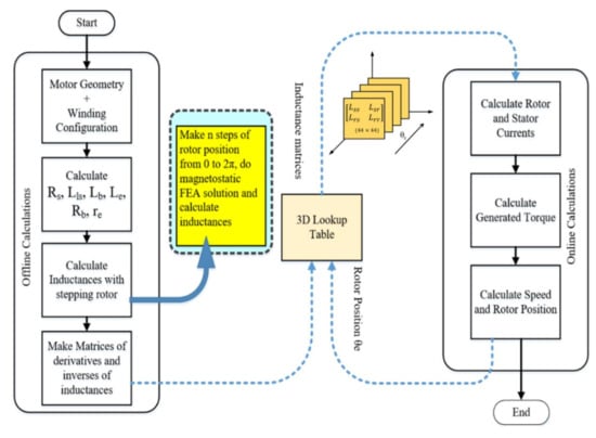
Figure 1.
The schematic diagram of inductances calculations and their implementations for dynamic simulation.
3. LAN Network for Cluster Formation
Parallel computing is a form of concurrent computing where several workouts can be performed in the overlapping periods. Generally, any large problem can be divided into n-small problems, which can be solved simultaneously. Unlike traditional serial programs, the divided problem segments should be independent of each other so that they can run on different processors and the solutions can be combined on the client machine at the end. The general schematic diagram of distributed parallel computation is shown in Figure 2. The client machines, job scheduler, WIFI or LAN network, and the worker processors, are the main parts of the distributed cloud computation. The function of the job scheduler is to divide and distribute the segments of the bigger problem into cluster computers. The cluster computers can further divide their portion among their cores in the same manner.
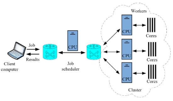
Figure 2.
The cluster formation and utilization for parallel processing.
4. Inductances Calculations
In the case of electrical machines, most of the faults such as eccentricity, broken bars, and stator inter-turn short circuits make the machines unsymmetrical. Due to this fact, the complexity reduction techniques such as exploitation of symmetry by considering symmetric and non-symmetric boundary conditions and model order reduction becomes more tedious. The only best optimal and reliable way for fault diagnostics is to simulate the entire machine at various rotor positions. Since the solution at a distinct rotor position is independent of the solution at subsequent rotor positions, the total “n” rotor steps can be divided into various segments. The magneto-static problems of different rotor position sectors such as, (0 → θ1), (θ2 → θ3), …, (θn-1 → θn), (θn+1 → 2π) can be divided among the workers for parallel processing.
Figure 3 shows the required steps to calculate the inductances at different rotor positions. The computer cluster consists of four computers making a local area network (LAN). Each computer is Intel(R) Core(TM) i7-7500 CPU @ 3.41 GHz with 8 GB RAM and four cores. The finite element method (FEM) based model is constructed using open-access software FEMM 4.0. For making the model and collecting the results, FEMM is interfaced with MATLAB. After making the machine geometry and winding configuration on FEMM, MATLAB works as a job scheduler. It divides the total number of rotor steps among worker computers and their cores and receives the end results.
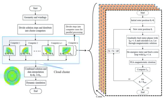
Figure 3.
The division of rotor steps among various computers and their cores for parallel computation and the procedure of inductances calculation.
For better accuracy, a considerable number of mesh elements (250,160) with (125,177) nodes are solved having a precision of 1 × 10⁻⁸ at each rotor step. The FEMM 4.0 achieves this precision through a conjugate gradient solver with the help of multiple successive approximation iterations. Since the inductance profiles change with the change in the air gap, the selection of an appropriate rotor step size is very important. The changing air gap is the function of stator and rotor slot openings [37], which becomes very prominent when the openings on both sides align with each other and lead to the abruptly changing inductance derivatives. As the rotor and stator, slots are different in number, their least count multiple (LCM) can be a minimum choice regarding the number of rotor steps. By doing so, some phase inductances can be considered as shifted copies of the other phase inductances. In this case, the number of total rotor steps or solution samples will be divisible by the total number of rotor bars and the number of samples corresponding to 120 and 240 degrees for stator phases. For example, if the number of rotor steps is (40 × 48 = 1920), the Lbb will be equal to (120 × 1920/360) samples shifted copy of Laa. The same is true in the case of rotor bar inductances, only self and mutual inductances of a single loop need to be calculated, the rest of them are shifted copies. However, special attention is needed if the fault changes all the inductances symmetrically or not.
5. The Simulation Results
At each rotor position, every individual stator phase is energized with a unity DC current, and relevant inductances are calculated by integrating the magnetic vector potential over the coil area as shown by the following equations.
where A is the vector potential, J is the current density, n is the number of turns per phase, i is the phase current, the subscript “si” is for surface integral. The first bracket term in Equation (16) is the integration of the vector potential of coils with positive current or the coils pointing out of the page. The second term corresponds to the coils with negative current or pointing into the page, a2 is the cross-sectional area of the coil, which is approximately equal to the slot area multiplied with the filling factor. The motor’s magnetic flux distribution after the energizing phase “a” with 1 A DC current is shown in Figure 4. The highlighted slots contain phase “a” winding whose surface integral of magnetic potential is equal to self-inductance Laa at the specific rotor position as in Equation (15).
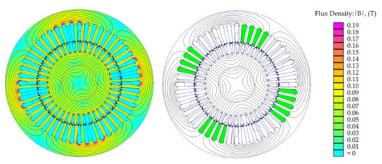
Figure 4.
The flux distribution with energized phase “a” with IDC = 1 A, and the selection of slots for vector potential integral for calculation of self-inductance Laa.
Similarly, all stator–stator self and mutual and stator–rotor mutual inductances can be calculated. The rotor–rotor self and mutual inductances are calculated by energizing a single rotor loop with unity DC current as shown in Figure 5. Only one rotor loop needs to be energized and solved for its inductances, and the rest of them possess the same solution with a phase shift equal to the angle difference between them.
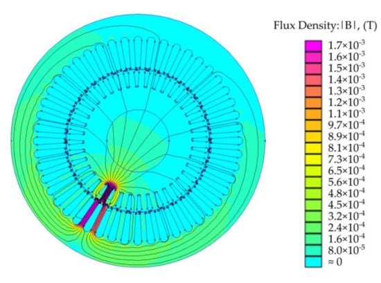
Figure 5.
Flux distribution due to energized rotor loop with IDC = 1 A for the calculation of rotor inductances.
Since the solution is for the 2D model, the effect of end windings is compensated by using additional end winding leakage inductance and resistance using the following analytical formulas.
where Qs is the number of stator slots, Zq is the number of conductors per slot, a is the number of winding parallel paths per phase, m is the total number of stator phases, and q is the number of slots in a pole captured by an individual phase. lw is the average length of the end winding, λw is the permeance factor which is 0.20 for the motor under investigation. The same formula can be used to calculate the leakage inductance of the rotor end rings. For building the resistance matrix, various stator- and rotor-related resistances are calculated using resistivity formula where the skinning and proximity effects are neglected because of the DC supply current;
where ρ is the resistivity, A is the cross-sectional area, and l is the length of the conductor. The effective slot area (ESA) is equal to the total area of slot multiplied with the filling factor, which is 0.60 for the machine under investigation. The conductor cross-sectional area can be calculated by dividing the ESA with the total number of conductors in the slot, which are 17 in this case. The resistance of the end windings is included by increasing the length of the per phase conductor corresponding to the length of the end winding. Since the stator and rotor windings are energized with unity DC current, the effects such as proximity, skinning, material saturation, and eddy currents are neglected as the focus is towards the simulation time reduction. However, they can be included in the online section analytically.
Figure 6 shows various inductances as a function of the rotor position. All self and mutual inductances are the functions of the air gap, which changes with the stepping rotor. This phenomenon is evident in the inductance profiles, which are calculated with a rotor step size of 0.1875 degrees. The self- and mutual inductances of stator have five cycles until an angle of 45 degrees, which corresponds to 40 cycles until 360 degrees. This is because the rotor has 40 bars having 40 slot openings. The stator inductances consider the stator air gap as static while rotor associated air gap moves with the moving rotor. The same is true for rotor self- and mutual inductances, which have six cycles per 45 degrees corresponding to 48 cycles till 360 degrees. Where 48 is the number of stator slots and for rotor inductances, the rotor-associated air gap remains static while the stator gap has a relative motion.
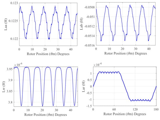
Figure 6.
The calculated inductances as a function of the rotor position.
6. Test Setup
The test rig consists of two identical motors with specifications given in Table 1. Both machines are attached back to back on the same mechanical foundation as shown in Figure 7. The first motor is the test motor while the second acts as a loading machine. The grid supplies the test machine while the loading motor is controlled using ABB ACS-880 industrial inverter for better controllability of slip. The measurement time of the stator current of the test machine under healthy and broken bar cases is 100 sec with a sampling frequency of 10 kHz.

Table 1.
Motor specifications.
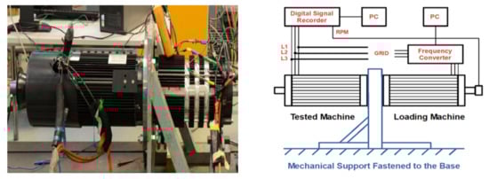
Figure 7.
The test rig and its block diagram.
7. Results and Discussion
7.1. Stator Current Spectrum under Healthy and Broken Rotor Bar Cases
The varying inductances give rise to the harmonics in the stator voltage and currents. The most prominent of them are supply based and spatial harmonics. A comparison of the frequency spectrum of stator current obtained from the proposed model and the measurements taken from the laboratory test rig is shown in Figure 8. The only additional harmonics in the practical signal are the third harmonics coming from the supply side. Another major source of harmonics in the signal spectrum is the fault, which can act as a definition component for condition monitoring. Figure 9 shows the development of the left side harmonics (LSH) due to the broken bars at the rated load.
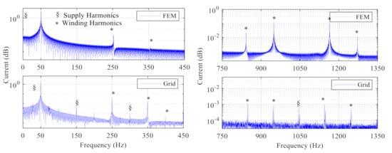
Figure 8.
The frequency spectrum of stator current obtained from the proposed model and laboratory-based measurements.
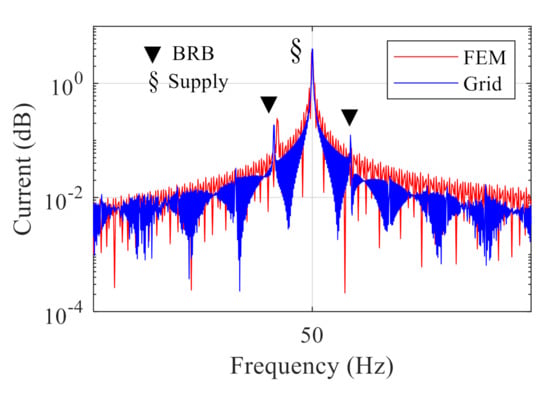
Figure 9.
The broken rotor bars-based side-band frequencies.
7.2. Time Comparison
The overall computational speed of each worker (computer) can be increased by using all cores in a parallel fashion. This increase in speed is because of increased cache, which reduces memory latency; the parallel handling of the independent instructions; and the improved performance of the processor power wall. The per-step computational time for the calculation of inductances relevant to a single phase (Laa, Lab, Lac, and Lar) at different rotor positions by using the different number of cores is shown in Figure 10a. Since, with the increase in the number of cores, more processing power is being utilized, the per-step calculation time increases. Moreover, the variation in the calculation time with the increase in the number of cores also increases, which depends upon the processor being utilized by auxiliary programs like Windows, etc. Figure 10b shows the mean per-step simulation time, which increases from 100 to 200 s per step with the increase in the utilization of processing power from about 25% (one core) to 94% (four cores). The mean simulation time is calculated because each step takes a slightly different time for calculation because of the change in the number of mesh elements and the other programs running in parallel. The overall calculation time for all inductances for 1920 rotor positions is shown in Figure 10c. It is obvious that even the per step simulation time with an increase in the parallel processing increases, but the total calculation time decreases dramatically. Meanwhile, Figure 10d shows the time taken by the cluster of four computers working as a LAN. The simulation time decreases considerably and the non-linear decrease in time is due to the latency of the network. It is worth mentioning that the job scheduler prefers cores of different computers to work in parallel. This is the reason why the computational time in Figure 10d with four cores of different computers working in parallel is considerably less than the time taken by one computer with all four cores engaged in parallel as shown in Figure 10c.
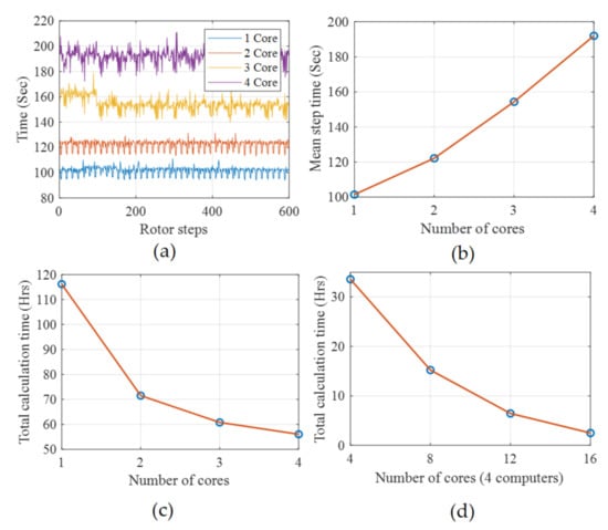
Figure 10.
The simulation time, (a) per step with different number of single computer workers (cores) in parallel, (b) the mean per-step time with different number of cores of a single computer working in parallel, (c) overall time on one computer with different cores engaged in parallel, (d) overall time with different number of computers making a cluster with distributed cores in parallel.
8. Conclusions
This paper presents a hybrid FEM–analytical model solved in a parallel fashion on a cluster of computers for the reduction of computational time. The artificial intelligence (AI) based condition-monitoring techniques for predictive maintenance of electrical machines is gaining heightened popularity. This is not only because of their ability to detect faults at the incipient stage but also because of their aptitude for faults segregation. The accurate model of the electrical machines is the key element of these techniques, which is crucial for the collection of big data under various healthy and faulty conditions. This data is essential for the training of the diagnostic systems and for making the safety rules. Among several modeling techniques, the FEM-based models have proved their accuracy in the field of electrical machine design for the past few decades. The FEM models have very few approximations and can deal with almost any kind of geometrical complexities of the system as compared to their analytical counterparts. The analytical models have their own attractions, such as the reduced simulation time and the development of analytical equations, which are integral parts of drives and inverse problem theory, etc. The biggest challenge for FEM-based models is their complexity in the forms of computational time and required memory. While on the analytical side, the approximations are fatal for any reliable diagnostic algorithm. The world is witnessing the exponentially increasing trend in the power of processors and sophisticated IT networks, which leads toward cloud computation and industry 4.0 standards.
By exploiting the benefits of analytical, FEM models, and cloud computation, this paper proposes a hybrid analytical–FEM model for the simulation of the machine under healthy and faulty conditions with reduced calculation time. Most of the techniques dealing with the reduction in the simulation time of FEM models fail when the machine is in a faulty condition, which makes it purely unsymmetrical. Moreover, any approximation for the sake of reduced complexity can decrease the reliability of the model-dependent diagnostic algorithm. With the development of more sophisticated processors and industry 4.0 standards, the complete models of the system can be solved in very much less time as compared to the conventional techniques. In this paper, the model is first divided into offline and online portions. All the inductances and other necessary parameters are calculated in the offline section, and the results are saved in 3D matrices as a function of rotor position. Once the inductances are calculated, they can be used in an online dynamic model where the performance parameters such as speed, torque, flux, and currents can be investigated under different conditions. In the case of some faults such as broken bars or broken end rings, the inductance matrices need not be calculated again but the fault can be manipulated in the online portion. This can be achieved by changing the values of the corresponding elements in the resistance matrix. For reducing the calculation time, the FEM model is divided into several computers before dividing the specific portion into the cores of any particular processor. For making a computer cluster resembling a cloud, four computers having the same specifications were used as a local area network. The total rotor steps were then divided into several cores working in parallel and the results were collected on the main computer. This technique reduces the simulation time drastically without any need for model approximation. For the validation of results, the frequency spectrum of simulated stator current is compared with the one measured in the laboratory setup under healthy and broken rotor bar cases.
Author Contributions
Conceptualization, B.A., T.V., and A.B.; methodology, B.A., T.V., and A.B.; validation, A.K., A.R., and A.B.; data curation, B.A.; writing—original draft preparation, B.A.; writing—review and editing, A.R., and M.N.I.; visualization, T.V.; supervision, T.V., and A.B. All authors have read and agreed to the published version of the manuscript.
Funding
This research received no external funding.
Conflicts of Interest
The authors declare no conflict of interest.
References
- Saidur, R. A review on electrical motors energy use and energy savings. Renew. Sustain. Energy Rev. 2010, 14, 877–898. [Google Scholar] [CrossRef]
- Sahraoui, M.; Cardoso, A.J.M.; Ghoggal, A. The use of a modified prony method to track the broken rotor bar characteristic frequencies and amplitudes in three-phase induction motors. IEEE Trans. Ind. Appl. 2015, 51, 2136–2147. [Google Scholar] [CrossRef]
- Naha, A.; Samanta, A.K.; Routray, A.; Deb, A.K. Low Complexity Motor Current Signature Analysis Using Sub-Nyquist Strategy with Reduced Data Length. IEEE Trans. Instrum. Meas. 2017, 66, 3249–3259. [Google Scholar] [CrossRef]
- Asad, B.; Vaimann, T.; Belahcen, A.; Kallaste, A.; Rassõlkin, A.; Iqbal, M.N. Broken rotor bar fault detection of the grid and inverter-fed induction motor by effective attenuation of the fundamental component. IET Electr. Power Appl. 2019, 13, 2005–2014. [Google Scholar] [CrossRef]
- Zhen, D.; Wang, T.; Gu, F.; Ball, A. Fault diagnosis of motor drives using stator current signal analysis based on dynamic time warping. Mech. Syst. Signal Process. 2013, 34, 191–202. [Google Scholar] [CrossRef]
- Garcia-Ramirez, A.G.; Morales-Hernandez, L.A.; Osornio-Rios, R.A.; García-Pérez, A.; Romero-Troncoso, R.D.J. Thermographic Technique as a Complement for MCSA in Induction Motor Fault Detection. In Proceedings of the 2014 International Conference on Electrical Machines (ICEM), ICEM 2014, Berlin, Germany, 2–5 September 2014; pp. 1940–1945. [Google Scholar]
- Taheri-Garavand, A.; Ahmadi, H.; Omid, M.; Mohtasebi, S.S.; Mollazade, K.; Smith, A.J.R.; Carlomagno, G.M. An intelligent approach for cooling radiator fault diagnosis based on infrared thermal image processing technique. Appl. Therm. Eng. 2015, 87, 434–443. [Google Scholar] [CrossRef]
- Glowacz, A.; Glowacz, Z. Diagnostics of stator faults of the single-phase induction motor using thermal images, MoASoS and selected classifiers. Measurement 2016, 93, 86–93. [Google Scholar] [CrossRef]
- Luong, P.; Wang, W. Smart Sensor-Based Synergistic Analysis for Rotor Bar Fault Detection of Induction Motors. IEEE/ASME Trans. Mechatronics 2020, 25, 1067–1075. [Google Scholar] [CrossRef]
- Caesarendra, W.; Kosasih, B.; Tieu, A.K.; Zhu, H.; Moodie, C.A.; Zhu, Q. Acoustic emission-based condition monitoring methods: Review and application for low speed slew bearing. Mech. Syst. Signal Process. 2016, 72–73, 134–159. [Google Scholar] [CrossRef]
- Vaimann, T.; Sobra, J.; Belahcen, A.; Rassõlkin, A.; Rolak, M.; Kallaste, A. Induction machine fault detection using smartphone recorded audible noise. IET Sci. Meas. Technol. 2018, 12, 554–560. [Google Scholar] [CrossRef]
- Henao, H.; Demian, C.; Capolino, G.-A. A frequency-domain detection of stator winding faults in induction machines using an external flux sensor. IEEE Trans. Ind. Appl. 2003, 39, 1272–1279. [Google Scholar] [CrossRef]
- Frosini, L.; Harlisca, C.; Szabo, L. Induction Machine Bearing Fault Detection by Means of Statistical Processing of the Stray Flux Measurement. IEEE Trans. Ind. Electron. 2015, 62, 1846–1854. [Google Scholar] [CrossRef]
- Stone, G.C.; Sedding, H.G.; Chan, C. Experience With Online Partial-Discharge Measurement in High-Voltage Inverter-Fed Motors. IEEE Trans. Ind. Appl. 2018, 54, 866–872. [Google Scholar] [CrossRef]
- Mirzaeva, G.; Saad, K.I.; Jahromi, M.G. Comprehensive Diagnostics of Induction Motor Faults Based on Measurement of Space and Time Dependencies of Air Gap Flux. IEEE Trans. Ind. Appl. 2017, 53, 2657–2666. [Google Scholar] [CrossRef]
- Liu, R.; Yang, B.; Zio, E.; Chen, X. Artificial intelligence for fault diagnosis of rotating machinery: A review. Mech. Syst. Signal Process. 2018, 108, 33–47. [Google Scholar] [CrossRef]
- Konar, P.; Chattopadhyay, P. Bearing fault detection of induction motor using wavelet and Support Vector Machines (SVMs). Appl. Soft Comput. 2011, 11, 4203–4211. [Google Scholar] [CrossRef]
- Li, X.; Wang, K.; Jiang, L. The Application of AE Signal in Early Cracked Rotor Fault Diagnosis with PWVD and SVM. J. Softw. 2011, 6, 1969–1976. [Google Scholar] [CrossRef]
- Soualhi, A.; Medjaher, K.; Zerhouni, N. Bearing Health Monitoring Based on Hilbert–Huang Transform, Support Vector Machine, and Regression. IEEE Trans. Instrum. Meas. 2015, 64, 52–62. [Google Scholar] [CrossRef]
- Sadeghian, A.; Ye, Z.; Wu, B. Online Detection of Broken Rotor Bars in Induction Motors by Wavelet Packet Decomposition and Artificial Neural Networks. IEEE Trans. Instrum. Meas. 2009, 58, 2253–2263. [Google Scholar] [CrossRef]
- Bin, G.F.; Gao, J.J.; Li, X.J.; Dhillon, B.S. Early fault diagnosis of rotating machinery based on wavelet packets—Empirical mode decomposition feature extraction and neural network. Mech. Syst. Signal Process. 2012, 27, 696–711. [Google Scholar] [CrossRef]
- Prieto, M.D.; Cirrincione, G.; Espinosa, A.G.; Ortega, J.A.; Henao, H. Bearing Fault Detection by a Novel Condition-Monitoring Scheme Based on Statistical-Time Features and Neural Networks. IEEE Trans. Ind. Electron. 2013, 60, 3398–3407. [Google Scholar] [CrossRef]
- Wang, J.; Liu, S.; Gao, R.X.; Yan, R. Current envelope analysis for defect identification and diagnosis in induction motors. J. Manuf. Syst. 2012, 31, 380–387. [Google Scholar] [CrossRef]
- Palácios, R.H.C.; Da Silva, I.N.; Goedtel, A.; Godoy, W.F. A comprehensive evaluation of intelligent classifiers for fault identification in three-phase induction motors. Electr. Power Syst. Res. 2015, 127, 249–258. [Google Scholar] [CrossRef]
- Wan, X.; Wang, D.; Tse, P.W.; Xu, G.; Zhang, Q. A critical study of different dimensionality reduction methods for gear crack degradation assessment under different operating conditions. Measurement 2016, 78, 138–150. [Google Scholar] [CrossRef]
- Ali, M.Z.; Shabbir, N.S.K.; Zaman, S.M.K.; Liang, X. Single- and Multi-Fault Diagnosis Using Machine Learning for Variable Frequency Drive-Fed Induction Motors. IEEE Trans. Ind. Appl. 2020, 56, 2324–2337. [Google Scholar] [CrossRef]
- Shao, S.; Yan, R.; Lu, Y.; Wang, P.; Gao, R.X. DCNN-Based Multi-Signal Induction Motor Fault Diagnosis. IEEE Trans. Instrum. Meas. 2020, 69, 2658–2669. [Google Scholar] [CrossRef]
- Jung, U.; Koh, B.-H. Wavelet energy-based visualization and classification of high-dimensional signal for bearing fault detection. Knowl. Inf. Syst. 2015, 44, 197–215. [Google Scholar] [CrossRef]
- Pandya, D.H.; Upadhyay, S.H.; Harsha, S.P. Fault diagnosis of rolling element bearing with intrinsic mode function of acoustic emission data using APF-KNN. Expert Syst. Appl. 2013, 40, 4137–4145. [Google Scholar] [CrossRef]
- He, D.; Li, R.; Zhu, J. Plastic Bearing Fault Diagnosis Based on a Two-Step Data Mining Approach. IEEE Trans. Ind. Electron. 2013, 60, 3429–3440. [Google Scholar] [CrossRef]
- Baccarini, L.M.R.; De Menezes, B.R.; Caminhas, W.M. Fault induction dynamic model, suitable for computer simulation: Simulation results and experimental validation. Mech. Syst. Signal Process. 2010, 24, 300–311. [Google Scholar] [CrossRef]
- Cunha, C.C.M.; Oliveira, P.; Lyra, R.; Filho, B.C. Simulation and analysis of induction machines with rotor asymmetries. IEEE Trans. Ind. Appl. 2005, 41, 18–24. [Google Scholar]
- Liang, J.; Qiu, Y.; Zhao, M.; Kang, S.; Lu, H. The modeling and numerical simulations of wind turbine generation system with free vortex method and simulink. Energy Convers. Manag. 2015, 103, 762–777. [Google Scholar]
- Lubin, T.; Hamiti, T.; Razik, H.; Rezzoug, A. Comparison Between Finite-Element Analysis and Winding Function Theory for Inductances and Torque Calculation of a Synchronous Reluctance Machine. IEEE Trans. Magn. 2007, 43, 3406–3410. [Google Scholar]
- Raziee, S.M.; Misir, O.; Ponick, B. Winding Function Approach for Winding Analysis. IEEE Trans. Magn. 2017, 53, 1–9. [Google Scholar]
- Nandi, S. A Detailed Model of Induction Machines With Saturation Extendable for Fault Analysis. IEEE Trans. Ind. Appl. 2004, 40, 1302–1309. [Google Scholar]
- Asad, B.; Vaimann, T.; Belahcen, A.; Kallaste, A.; Rassõlkin, A.; Iqbal, M.N. Modified winding function-based model of squirrel cage induction motor for fault diagnostics. IET Electr. Power Appl. 2020, 14, 1722–1734. [Google Scholar]
- Sudhoff, S.D.; Kuhn, B.T.; Corzine, K.A.; Branecky, B.T. Magnetic Equivalent Circuit Modeling of Induction Motors. IEEE Trans. Energy Convers. 2007, 22, 259–270. [Google Scholar]
- Apsley, J.M.; Williamson, S. Analysis of Multi-Phase Induction Machines with Winding Faults. In Proceedings of the IEEE International Conference on Electric Machines and Drives, San Antonio, TX, USA, 15 May 2005; pp. 249–255. [Google Scholar]
- Wang, L.; Jatskevich, J.; Pekarek, S.D. Modeling of induction machines using a voltage-behind-reactance formulation. IEEE Trans. Energy Convers. 2008, 23, 382–392. [Google Scholar]
- Sapena-Bano, A.; Martinez-Roman, J.; Puche-Panadero, R.; Pineda-Sanchez, M.; Perez-Cruz, J.; Riera-Guasp, M. Induction machine model with space harmonics for fault diagnosis based on the convolution theorem. Int. J. Electr. Power Energy Syst. 2018, 100, 463–481. [Google Scholar]
- Ding, Q.; Yang, Z.; Sun, X.; Zhao, Q.; Zhu, H. Analysis of rotor slot width influence on a bearingless induction motor. Comput. Electr. Eng. 2020, 81, 106534. [Google Scholar]
- Belahcen, A.; Rasilo, P.; Arkkio, A. Segregation of Iron Losses From Rotational Field Measurements and Application to Electrical Machine. IEEE Trans. Magn. 2014, 50, 893–896. [Google Scholar] [CrossRef]
- Zhang, H. Online Thermal Monitoring Models for Induction Machines. IEEE Trans. Energy Convers. 2015, 30, 1–9. [Google Scholar] [CrossRef]
- Zhang, Y.; Ruan, J.; Huang, T.; Yang, X.; Zhu, H.; Yang, G. Calculation of Temperature Rise in Air-cooled Induction Motors Through 3-D Coupled Electromagnetic Fluid-Dynamical and Thermal Finite-Element Analysis. IEEE Trans. Magn. 2012, 48, 1047–1050. [Google Scholar] [CrossRef]
- Bourchas, K.; Stening, A.; Soulard, J.; Broddefalk, A.; Lindenmo, M.; Dahlen, M.; Gyllensten, F. Quantifying Effects of Cutting and Welding on Magnetic Properties of Electrical Steels. IEEE Trans. Ind. Appl. 2017, 53, 4269–4278. [Google Scholar] [CrossRef]
- Sapena-Bano, A.; Chinesta, F.; Pineda-Sanchez, M.; Aguado, J.; Borzacchiello, D.; Puche-Panadero, R. Induction machine model with finite element accuracy for condition monitoring running in real time using hardware in the loop system. Int. J. Electr. Power Energy Syst. 2019, 111, 315–324. [Google Scholar] [CrossRef]
- Ghahfarokhi, P.S.; Belahcen, A.; Kallaste, A.; Vaimann, T.; Gerokov, L.; Rassolkin, A. Thermal Analysis of a SynRM Using a Thermal Network and a Hybrid Model. In Proceedings of the 2018 23rd International Conference on Electrical Machines, ICEM 2018, Alexandroupoli, Greece, 3–6 September 2018; pp. 2682–2688. [Google Scholar]
- Mukhrejee, V.; Far, M.F.; Martin, F.; Belahcen, A. Constrained Algorithm for the Selection of Uneven Snapshots in Model Order Reduction of a Bearingless Motor. IEEE Trans. Magn. 2017, 53, 1–4. [Google Scholar] [CrossRef]
- Far, M.F.; Martin, F.; Belahcen, A.; Rasilo, P.; Awan, H.A.A. Real-Time Control of an IPMSM Using Model Order Reduction. IEEE Trans. Ind. Electron. 2020, 1. [Google Scholar] [CrossRef]
- Far, M.F.; Martin, F.; Belahcen, A.; Montier, L.; Henneron, T. Orthogonal Interpolation Method for Order Reduction of a Synchronous Machine Model. IEEE Trans. Magn. 2018, 54, 1–6. [Google Scholar]
- Borzacchiello, D.; Aguado, J.V.; Chinesta, F. Non-intrusive Sparse Subspace Learning for Parametrized Problems. Arch. Comput. Methods Eng. 2019, 26, 303–326. [Google Scholar] [CrossRef]
- Villalonga, A.; Beruvides, G.; Castano, F.; Haber, R.E. Cloud-Based Industrial Cyber–Physical System for Data-Driven Reasoning: A Review and Use Case on an Industry 4.0 Pilot Line. IEEE Trans. Ind. Informatics 2020, 16, 5975–5984. [Google Scholar] [CrossRef]
- Chen, Z.; Quan, W.; Wen, M.; Fang, J.; Yu, J.; Zhang, C.; Luo, L. Deep Learning Research and Development Platform: Characterizing and Scheduling with QoS Guarantees on GPU Clusters. IEEE Trans. Parallel Distrib. Syst. 2020, 31, 34–50. [Google Scholar] [CrossRef]
- Gao, Y.; Ai, Y.; Tian, B.; Chen, L.; Wang, J.; Cao, D.; Wang, F.-Y. Parallel End-to-End Autonomous Mining: An IoT-Oriented Approach. IEEE Internet Things J. 2020, 7, 1011–1023. [Google Scholar] [CrossRef]
- Bandyopadhyay, I.; Purkait, P.; Koley, C. A combined image processing and Nearest Neighbor Algorithm tool for classification of incipient faults in induction motor drives. Comput. Electr. Eng. 2016, 54, 296–312. [Google Scholar] [CrossRef]
- Guesmi, H.; Ben Salem, S.; Bacha, K. Smart wireless sensor networks for online faults diagnosis in induction machine. Comput. Electr. Eng. 2015, 41, 226–239. [Google Scholar] [CrossRef]
- Chen, J.; Li, K.; Bilal, K.; Zhou, X.; Li, K.; Yu, P.S. A Bi-layered Parallel Training Architecture for Large-Scale Convolutional Neural Networks. IEEE Trans. Parallel Distrib. Syst. 2019, 30, 965–976. [Google Scholar] [CrossRef]
- You, Y.; Zhang, Z.; Hsieh, C.-J.; Demmel, J.; Keutzer, K. Fast Deep Neural Network Training on Distributed Systems and Cloud TPUs. IEEE Trans. Parallel Distrib. Syst. 2019, 30, 2449–2462. [Google Scholar] [CrossRef]
- Huang, S.-R.; Huang, K.-H.; Chao, K.-H.; Chiang, W.-T. Fault analysis and diagnosis system for induction motors. Comput. Electr. Eng. 2016, 54, 195–209. [Google Scholar] [CrossRef]


Publisher’s Note: MDPI stays neutral with regard to jurisdictional claims in published maps and institutional affiliations. |
© 2020 by the authors. Licensee MDPI, Basel, Switzerland. This article is an open access article distributed under the terms and conditions of the Creative Commons Attribution (CC BY) license (http://creativecommons.org/licenses/by/4.0/).