Abstract
Mechanical damage in form of dents, cracks, gouges, and scratches are common in pipelines. Sometimes, these damages form in proximity of each other and act as one defect in the pipe wall. The combined defects have been found to be more injurious than individual defects. One of the combined defects in pipeline comprises of a crack in a dent, also known as dent-crack defect. This paper discusses the development of finite element models using extended finite element criterion (XFEM) in Abaqus to predict burst pressure of specimens of API X70 pipeline with restrained and unrestrained concentric dent-crack defects. The models are calibrated and validated using results of full-scale burst tests. The effects of crack length, crack depth, dent depth, and denting pressure on burst pressure are investigated. The results show that restrained dent-crack defects with shallow cracks (depth less than 50% wall thickness) inside dents do not affect pipeline operations at maximum allowable operating pressure if crack lengths are less than 200 mm. Releasing restrained dent-cracks when the pressure is at maximum allowable operating pressure can cause propagation of deep cracks (depth of 50% wall thickness or more) longer than 60 mm. However, only very long cracks (200 mm and higher) propagate to burst the pipe. Cracks of depth less than 20% of wall thickness inside dents formed at zero pressure are not propagated by the maximum allowable operating pressure. Dent-crack defects having dents of depth less than 2% outside diameter of pipe behave as plain cracks if the dents are formed at zero denting pressure but are more injurious than plain cracks if the dents are formed in pressurized pipes.
Keywords:
dents; cracks; strength; integrity; extended finite element; burst pressure; stress; strain 1. Introduction
Mechanical damage like cracks, scratches, and gouges often occur inside dents in pipelines. The combined defects are considered more injurious to pipeline integrity than plain defects [1,2,3,4,5,6]. An example of combined defects found in pipelines is a crack inside a dent, also known as a dent-crack defect [2,3,4]. Vilkys et al. [7] showed that gouge depths greater than 50% of wall thickness cause stresses higher than yield strength of pipe material and cracks are likely to initiate at the tip of such gouges under normal operating pressure. The dent magnifies the maximum principal stresses developed in the gouge, increasing susceptibly to cracking. Ronny et al. [8] also showed that hoop stresses are higher in a pipeline with combined dent and gouge defects than in a pipeline with plain gouges and concluded that dent-gouge defects significantly lower the burst strength of pipelines.
Very few full-scale experimental studies on dent-crack defects in pipelines have been accomplished [2,3,4,5], mainly because of the difficulty in creating artificial cracks for experiments. Usually, the cracks are represented by notches and gouges [9] with a small fatigue crack at the tip. Currently, there are no analytical models for assessing the integrity of a pipeline with dent-crack defects. The pipeline defect assessment manual [10,11] recommends the use of dent-gouge fracture models to assess dent-crack, without taking the difference between the stress environments at the tip of cracks and gouges into consideration.
Oryniak et al. [12] proposed a model for assessing dent-crack defects based on the stress distribution in a dent with an axial crack lodged at its deepest point by treating the dent as a source of geometric nonlinearity. Bending stresses through the crack caused by the geometric nonlinearity were added to the stresses caused by the internal pressure and the sum used to calculate the stress intensity factor used to analyze crack propagation. The model is considered conservative because it does not account for the effect of re-rounding of dents under internal pressure on the bending stresses through the crack. Bai et al. [13] used a notch in an infinitely long dent to represent a dent-crack defect and then modified the plastic collapse stress of the pipe material to account for deterioration in the material properties due to the mechanical damage during defect formation and the effect of notch shape. They considered the modified collapse stress as the burst stress of the pipe, and a fraction of it was used to compute burst pressure. The main limitation of their approach is that they used a notch instead of a crack.
In the absence of analytical models, the finite element method (FEA) has been successfully used to evaluate burst pressures of pipelines with dent-crack defects [2,3,4]. But, it lacks an in-built criterion for determining burst pressure. The software user must choose one out of several that have been suggested in literature. Das et al. [14] used a threshold for equivalent plastic strain in the defect area to analyze fatigue fracture. Adeeb and Horsley [15] used 20% maximum principal strain as the critical strain for safe excavation of defective pipes in a rock ditch, considering material fails at 20% strain. Tian and Zhang [16] used an equivalent stress criterion to assess burst strength of pipes with dent-scratch defect, considering failure to occur when the equivalent stress equals the true tensile strength of the pipe material. Other studies [2,3,4,17] used the J-integral concept, assuming failure occurred when the J-integral at any integration point in the model equaled a critical value of the material. All the above FEA failure criteria use material properties and geometry of pipe, which are altered by denting and rebound action of dents [18], further introducing uncertainty in the results.
The extended finite element method (XFEM) uses damage parameters determined through calibration and input in the model as material properties. Any moderating effects of denting and re-rounding of dents on material properties and fracture behavior is considered in the calibration process. The cracks in XFEM models propagate when the value of strains, stresses, and fracture energy or displacements at any point within the pipe exceed the calibrated damage parameters. Pressure required to propagate a part-wall crack to a through-wall crack is the burst pressure of the flawed pipeline, and crack growth is observed from the post processing graphics, which makes it easy to accurately determine the burst pressure of the pipeline [19].
This paper uses the XFEM procedure in Abaqus [20] to analyze propagation of longitudinal cracks inside restrained and un-restrained dent and predict burst pressure of pipeline with dent-crack defects. Pipeline specimens with longitudinal part-wall cracks inside dents are modeled and subjected to internal pressure to initiate and sustain crack propagation and burst the pipe.
XFEM uses the partition of unity concept to waive the need for mesh geometry to match crack geometry by introducing local enrichment functions and additional degrees of freedom in the standard FEM formulation [21,22,23]. An intra-element algorithm freely lays the crack within the mesh without tying it to element boundaries, thus overcoming the requirement to match the geometry of mesh to crack geometry. The software searches for regions of crack initiation where stresses and strains exceed a critical value, after which phantom nodes and their superposed original real nodes move apart as the crack propagates, following a specified traction separation law (TSL) and damage evolution criterion.
Abaqus standard [20] provides linear, exponential, and tabular TSL options and maximum principal stress (Maxps) or strain (Maxpe), and maximum nominal stress or strain for damage initiation criterion. Other damage initiation criteria options include quadratic nominal stress, quadratic nominal strain, and user-defined criterion. Damage evolution criteria include fracture energy and crack tip displacement.
2. Materials and Methods
2.1. Overview of Burst Tests
Burst test results and material properties of API X70 pipe samples with dent-crack defects were obtained from literature [2] and used to calibrate and validate finite element models for prediction of burst pressure. The pipes had outside diameter (OD) of 762 mm, wall thickness (t) of 8.5 mm, and length (L) of 2.5 m. Fatigue load actuators were used to create 0.3 mm deep fatigue cracks at the tip of 4 mm deep, crack-like v-shaped notches cut at the 12 O’clock position of the pipe using an electro-discharging machine (EDM). Thus, the total crack-like defect was 4.3 mm deep, approximately 50% of wall thickness and the four specimens used in this study had cracks with lengths (2c) × depth (a) of 20 × 4.3 mm, 60 × 4.3 mm, 100 × 4.3 mm, and 200 × 4.3 mm.
A rigid rectangular steel block attached to a universal loading actuator was used to create 50 mm wide by 100 mm long dents over the cracks, to obtain the desired dent-crack defects. Dent depth and plastic deformation during the denting process were monitored using linear variable differential transducers (LVDTs). The measured dent depth that remained upon releasing the indenter was 28 mm, approximately 4% OD of the pipe. A pressure of 3.8 MPa, equivalent to 30% of the yield pressure (Py) of the pipe, was maintained in the pipe as denting pressure during dent formation. The pressure was administered using a hydrostatic pump and monitored both manually and electronically through transducers. Strains along the pipe length were measured by strain gauges arranged on the pipe surface. Figure 1 shows the set-up of the burst tests.
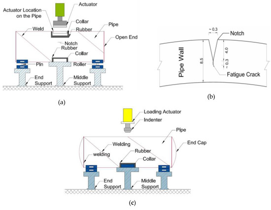
Figure 1.
Schematic diagram showing (a) fatigue loading, (b) fatigue crack, and (c) denting process (used with publisher’s consent granted under license number 1528-896X).
Monotonically increasing internal pressure was supplied to the flawed pipe specimens by a water pump to cause leakage or burst, upon which the test was discontinued. The pressure was monitored mechanically using pressure gauge and electronically using transducers. Table 1 shows the experimental and predicted burst pressures of the different pipe specimens used in the burst test. The pipes in the test had a 28 mm deep dent formed under a pressure of 3.8 MPa, equivalent to 30% of the yield pressure (Py = 12.67 MPa) of the pipe.

Table 1.
Burst pressures of different specimens.
2.2. Material Properties
Samples extracted from the pipe in accordance with procedures of the American Society for Testing and Materials, standard E8 (ASTM E8) were used in tensile tests. The material had a yield stress of 540 MPa (5% proof strain), tensile strength of 620 MPa, Young’s modulus E of 204 GPa, and Poisson’s ratio v of 0.3. Figure 2 shows the stress-strain curve of the pipe material. Charpy-V notch impact tests of five sub-size samples (full wall thickness in specimen sizes) taken from the pipe showed that the pipe material was sufficiently ductile. The material was reported to present a fully ductile fracture behavior, with approximate Charpy impact energy of 152 J at room temperature.
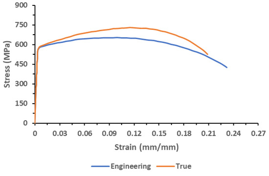
Figure 2.
Stress-strain curve of the pipe material.
2.3. Numerical Modelling
2.3.1. Overview
XFEM in Abaqus [20] was used to model the crack propagation. Maximum principal strain (Maxpe) and fracture energy (Gc) were used as damage parameters. The pipe material was modelled as elastic-plastic with isotropic hardening behavior. Denting of the pipe was accomplished by prescribing a maximum downward displacement load to the indenter as a boundary condition. A displacement load of 63.53 mm left an unrestrained dent of 4% OD depth upon releasing the rigid indenter from the pipe surface.
2.3.2. Setup of the Model
Figure 3a shows the setup of the model and the boundary conditions. Symmetry of the burst test set up along the z-axis (along pipe length) was used to model half of the pipe and reduce computational cost. The model comprised of a deformable solid strip of length 250 mm, width 20 mm, and thickness 8.5 mm, a deformable shell of OD 762 mm and length 1250 mm, with part of it cut out and replaced with the solid strip in which the crack was embedded. Shell geometry was defined by the top surface such that the pipe was assembled by joining the top edge of the shell to the top edge of the solid strip. Previous studies [19] show that shell elements work best when the section is offset at mid surface. The predictions are closer to predictions made using a fully solid model. But the analysis time is significantly longer than the time taken when shell geometry was offset at the top surface. Predictions with shell section offset at the top surface were within 10% of the solid model predictions and yet the analysis time was at least 4 times faster. Shell-solid coupling constraint was used for the transition between solid and shell elements in the pipe body. The crack was modelled as a rectangular planar shell embedded in the solid strip, while the indenter was modelled as a discrete rigid solid block placed at the 12 O’clock position of the pipe and over the crack. Surface-to-surface standard contact was prescribed between the pipe and the indenter. Z-symmetry boundary condition was applied along the circumferential edge of the pipe for symmetry along the z-axis. Vertical support was provided at the bottom of the pipe by restraining degree of freedom U2 against vertical displacement at locations on the pipe surface that were placed on steel blocks during the burst test. Kinematic constraint was used at the ends of the pipe with the geometric centers as reference points, fixed against displacement and rotation but allowing the pipe to freely expand.
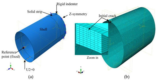
Figure 3.
Showing: (a) Model geometry; (b) Mesh distribution in the model.
2.3.3. Mesh Distribution
Eight-node linear brick elements (C3D8R) with reduced integration were used in the solid part of the pipe, while four-node (S4R) elements with quad-dominated free mesh were used in shell parts of the pipe. Mesh sensitivity analysis was done to optimize accuracy of prediction and reduce the time required to complete analysis. Predictions were very sensitive to size of elements in the solid part of the pipe having the crack. Therefore, fine mesh distribution was used in it, and coarse mesh in the rest of the pipe. Final element dimensions in the solid were 5 mm × 2.86 mm × 0.85 mm in the longitudinal, circumferential, and thickness directions of the pipe respectively, and element size of 18 mm was used for the shell elements. Figure 3b shows mesh distribution in the model, with fine mesh near the crack and coarse mesh away from the crack to reduce computation cost. A total of 10 elements were used in the thickness direction of the pipe.
2.3.4. Defect Configuration and Loading Sequence
Three common pipeline dent-crack defect configurations were investigated. The first defect configuration investigated was a pipe with an unrestrained dent-crack defect subjected to internal pressure. The denting load was applied through the indenter as a displacement. The indenter was released from the surface of the cracked pipe after loading, to create the unrestrained dent-crack and the flawed pipe was then subjected to internal pressure to propagate the crack. The second defect configuration was a pipe with a restrained dent-crack subjected to internal pressure. The indenter was left on the pipe surface after applying denting load and internal pressure was then applied to propagate the crack. This configuration simulates a pipe dented and cracked by a hard object on which it is placed during construction. The last configuration was a pipe with a restrained dent-crack defect, subjected to maximum allowable operating pressure (MAOP) of the pipe. The indenter was gradually released from the pipe surface with the pipe still at MAOP. The objective was to assess whether releasing the indenter at MAOP would propagate the dent-crack. Often in the field, an initially restrained dent is unrestrained circumstantially. In such a scenario, getting the maximum safe operating pressure that does not propagate an existing crack as the restraint is released becomes paramount. Figure 4 shows the steps used to vary the defect configurations investigated in this study. Different permutations of the steps produce different defect and loading scenarios in the pipe. Unrestrained dent-crack defects under internal pressure were realized using steps 1–4. Restrained dent-crack under internal pressure was created using steps 1, 2, and 4, eliminating step 3 altogether. Finally, the third scenario (release of indenter at MAOP) was simulated using steps 1, 2, 4, and 3, in that order, with the amount of pressure used in step 4 being the MAOP of the pipe. Parametric studies were conducted for the three defect scenarios by varying denting pressure, dent depth, and crack dimensions.
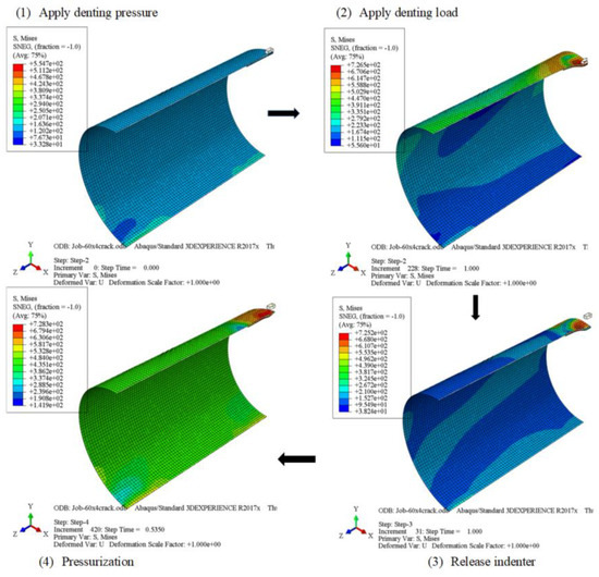
Figure 4.
Showing typical distribution of von Mises stress in the pipe at different loading steps followed in this study; Step 1: Apply denting pressure; Step 2: Dent the pipe; Step 3: Release the indenter from pipe surface; Step 4: Pressurize the pipe to propagate crack and burst the pipe.
2.3.5. Calibration and Validation of the Model
Maximum principal strain (Maxpe) with exponential traction separation law, were used as damage parameters for XFEM crack propagation. Available studies [19] show that model calibration can be successfully accomplished using either small-scale or full-scale test results. Burst test results were used to calibrate and validate the model in this study. Burst pressure of the specimen with 100 mm × 4.3 mm crack was used for calibration. The crack length in the specimen matched the dent length perfectly. Results of the three remaining specimens (20 mm × 4.3 mm, 60 mm × 4.3 mm, and 200 mm × 4.3 mm cracks) tested were used in validation. Damage parameters obtained from the calibration and validation process were fracture strain, Maxpe = 0.045, and fracture energy, Gc = 2 kJ/m2. High fracture strain and low fracture energy cause large plastic deformation followed by brittle crack propagation [24]. Resistance to propagation of a cohesive crack in elastic-plastic materials depends on material properties and damage parameters (cohesive strength and energy). According to Li and Chandra [25], the resistance is effected through plastic dissipation of energy in the material surrounding the fracture process zone and dissipation of cohesive energy inside the fracture process zone itself. Increasing cohesive strength (fracture strain) and strain hardening exponent increases the contribution of plasticity towards resistance of crack propagation but lowers contribution of cohesive energy (fracture energy). Large fracture strains show that the material has a high flow stress and require large loads to plasticize. The large loads produce large traction within the fracture process zone resulting in greater resistance to fracture. Low fracture energy shows that resistance to crack propagation is fundamentally by the plastic dissipation of energy in the material around the fracture process zone. A very low amount of energy is required to separate the surfaces within the cohesive zone to form the crack. Table 1 shows burst pressures of four specimens obtained from test and predictions made using the calibrated model. The result shows that the model is generally non-conservative, and predictions were within 10% of the test results.
Load-displacement curves [2] for the dent formation process in the experiments were used to validate the denting of the numerical model. Figure 5 shows load-displacement curves for application and release of the rigid indenter from the pipe surface. There is good agreement between test and model-derived curves for all specimens, but the maximum denting load of the model was on average 13% higher than maximum load from tests, showing the models was stiffer than the experiments. This is attributed to the firm supports achieved in modelling compared to supports used in experiments.
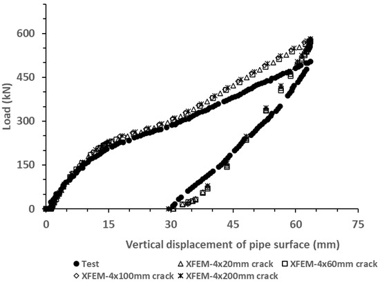
Figure 5.
Load-displacement curve for application and release of indenter.
3. Results and Discussion
3.1. Unrestrained Concentric Dent-Crack Defects
Figure 6 shows the Von Mises stress distribution at different stages of crack propagation through the wall of the specimen having a 60 mm × 4.3 mm crack at the center of a 4% OD deep unrestrained dent formed at 0.3 Py denting pressure. The crack does not propagate during dent formation but stresses at the tip are higher than the yield stress of the material (Figure 6b). When the internal pressure is applied, the dent rebounds to recover the circular pipe geometry before the crack begins to propagate through the wall as shown in Figure 6c. Fracture occurs with visible upward displacement of the internal surface of the pipe (Figure 6d,e) due to plasticization under sustained pressure, typical in specimens with deep cracks [24,26].
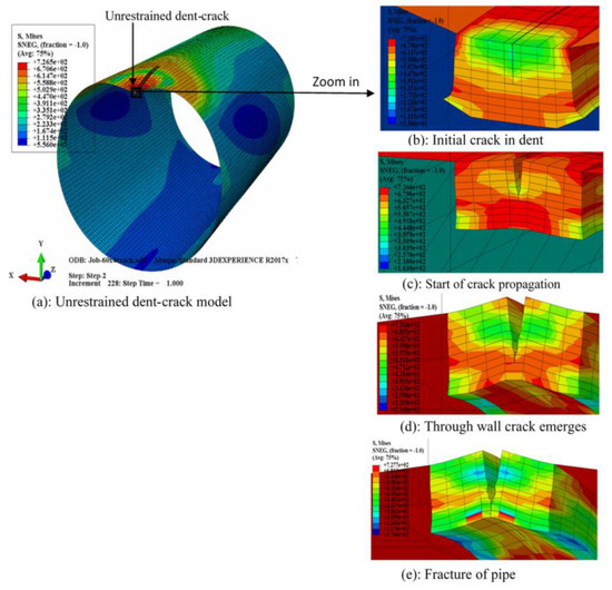
Figure 6.
Distribution of von Mises stress in pipe wall at various stages of propagation of a crack inside unrestrained dent: (a) Model of pipe with unrestrained concentric dent-crack; (b) Before applying pressure; (c) At start of crack propagation; (d) After through wall crack emerges inside pipe; (e) When crack has fully opened and fracture is complete.
Table 2 shows the effect of varying the defect parameters on the burst pressure of a pipe with unrestrained concentric dent-crack defect, considering crack depths of 1.7 mm (0.2 t) and 4.3 mm (0.5 t). Internal pressure (denting pressure) ranging from 0% to 80% of yield pressure, Py (Py = 12.67 MPa), was maintained in the pipe during dent formation as crack length and dent depths were varied.
Table 2.
Burst pressure of pipes with unrestrained concentric dent crack defects.
Denting the pipe at a pressure of 0.8Py (=10.13 MPa) caused cracks to propagate in the circumferential direction during formation of the unrestrained dent-crack because the total bending and membrane strains normal to the circumferential plane surpassed the threshold fracture strain in the process. The risk of circumferential propagation increased with dent depth and denting pressure. It was impossible to dent the pipe to 6% OD depth at 0.3 Py denting pressure with 200 mm long crack. Similarly, creating 6%OD deep dents at 0.5Py denting pressure was generally problematic for all crack lengths because large strains are involved.
3.1.1. Effect of Crack Depth on Burst Pressure
Unrestrained dent-cracks having 0.2 t deep cracks of any length inside dents less than 6% OD deep had no tangible effect on the burst pressure if the defects were formed at <0.5 Py denting pressure. A denting pressure of 0.5 Py for dents of depths < 6% OD and crack of lengths ≤ 200 mm, was not consequential to operations of pipeline if crack depths were ≤0.2 t. The pipes sustained pressures higher than 10.13 MPa -the MAOP of the pipe- without bursting. Most specimens with 0.2 t deep cracks inside dents sustained very high internal pressure and plasticized significantly without crack propagation. On the other hand, all specimens with 0.5 t deep crack in the dent failed by fracture and their burst pressures decreased with crack length, for all dent depths and denting pressures. Specimens with shallow cracks tend to fail by plastic collapse, while deeply cracked specimens tend to fail by fracture [19,24].
3.1.2. Effect of Crack Length on Burst Pressure
Crack length was varied from 20 to 200 mm while maintaining crack depth at 0.5t, varying dent depths from 0% to 6% OD, and denting pressures from 0 to 0.8 Py. Increasing crack length from 20 to 200 mm in a 2% OD deep dent formed at zero pressure caused a 25% drop in the burst pressure and a 36% drop for dent depths ≥4% OD. Dent-crack defects with ≤2% OD dent depths formed at 0 pressure had the same burst pressure as plain cracks (Figure 7a). With cracks of lengths >20 mm and dent depth >2% OD, dent cracks were more severe than plain cracks, as shown in Figure 7b,c, with the disparity increasing with crack length and denting pressure.
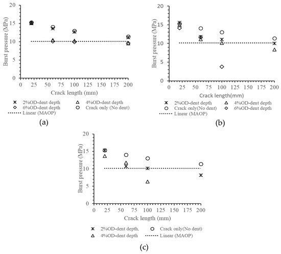
Figure 7.
Variation of burst pressure of specimens with 0.5 t deep crack inside dents of different depths formed at: (a) Denting pressure = 0, (b) Denting pressure = 0.3 Py; (c) Denting pressure = 0.5 Py.
According to Ghaednia et al. [2,3,4], dent-crack defects with cracks of 0.5 t depth inside dents of 4% OD depths were unable to sustain pressure equivalent to the MAOP of the pipe if crack lengths were greater than 75 mm, regardless of the pressure at which the dents were formed. This study shows that the margin of safety is higher and varies with pressure. All dents formed at zero pressure with a 0.5 t crack would sustain the MAOP for crack lengths < 200 mm as shown in Figure 7a, while Figure 7b shows that 0.5 t deep cracks inside 4%OD deep dents formed at 0.3 Py denting pressure have limiting length of 100 mm. The same defect if formed at 0.5 Py would have a limit length less than 100 mm.
Ghaednia et al. [2] applied the J-integral concept to decide whether the pipe had failed. Failure occurred when the J-integral value at any point in the crack reached 1.15 , the critical value of J-integral at which the material fractured. We believe, based on our analysis, that using the J-integral value at the tip of an existing crack to determine burst pressure of pipeline is conservative. Whereas crack growth in the model initiated at lower pressure, its progression beyond the immediate vicinity of the original crack tip was slowed by plasticity, enabling the pipes to sustain more pressure before bursting.
3.1.3. Effect of Dent Depth on Burst Pressure
Increasing the dent depth from 0% to 6% OD while keeping the crack length and the crack depth constant did not change the burst pressure if the dent was formed at zero pressure (Figure 8a). But, where denting of the pipe was accomplished with the pipe already under pressure, increasing the dent depths at constant crack length and crack depth reduced the burst pressure, as shown in Figure 8b,c. The rate of drop in the burst pressure with dent depth increased with crack length and denting pressure.
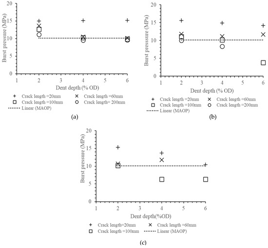
Figure 8.
Variation of burst pressure with dent depth, for pipes having 0.5 t deep cracks of various lengths inside dents formed at: (a) Denting pressure = 0, (b) Denting pressure = 0.3 Py; (c) Denting pressure = 0.5 Py.
Dent-crack defects having dents > 4% OD deep, formed at denting pressure > 0.3 Py with a crack of length > 100 mm and depth ≥ 0.5 t were likely to burst at pressures lower than MAOP of the pipe. All dents formed at 0.5 Py denting pressure and having crack of lengths > 100 mm inside them did not sustain the MAOP of the pipe.
3.1.4. Effect of Denting Pressure
Figure 9 shows the variation of the burst pressure with denting pressure for pipes having different dent depths and crack dimensions. The results show that dent-crack defects formed when the pipe was under pressure were more severe on burst strength. For a given crack length and dent depth, burst pressure dropped with increase in denting pressure. Specimens having crack length ≥ 100 mm in dents of depth ≥ 4% OD formed at 0.3 Py were likely to burst at pressures lower than MAOP of the pipe. All specimens with dents formed at 0.5 Py and having crack length ≥ 100 mm burst at pressures lower than MAOP. It is thus valid to say that dents augmented the effect of cracks on burst pressure, and denting pressure magnified the effect of the dent depth. Dent-crack defects formed at 0.3 Py or lower denting pressures sustained the MAOP if the dent depths are less than 4%OD and cracks inside the dents were less than 100 mm long and 0.5 t deep. Defects formed at 0.5 Py only sustained the MAOP if the crack lengths were less than 100 mm. As concluded by Ghaednia et al. [2], dent-crack defects having 4% OD deep dents formed at 0.3 Py are likely to sustain the MAOP if the crack length is <75 mm and crack depth is 0.5t.
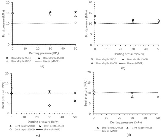
Figure 9.
Variation of burst pressure with denting pressure, for pipes with 0.5 t deep cracks of varied lengths inside dents of varied depths: (a) Crack length = 20 mm, (b) Crack length = 60 mm, (c) Crack length =100 mm and (d) Crack length = 200 mm.
3.2. Restrained Concentric Dent-Crack Defects
Figure 10 shows the von Mises stress distribution at different stages of crack propagation through the wall of the specimen having a 60 mm × 4.3 mm crack in a 4% OD deep restrained dent formed at 0.3 Py denting pressure. The remaining ligaments experienced large stresses similar to the ligaments in the unrestrained dent-cracks prior to the start of crack propagation under pressure. Plasticization accompanied fracture but upward displacement of the internal surface of the pipe was limited by the dent restraint. There is negligible difference between the pressure required to propagate the crack and burst pressure of the pipe with restrained dent. This is in sharp contrast with the response of pipes with unrestrained dent cracks, where the crack propagated at 9 MPa internal pressure and burst at 11.14 MPa internal pressure.
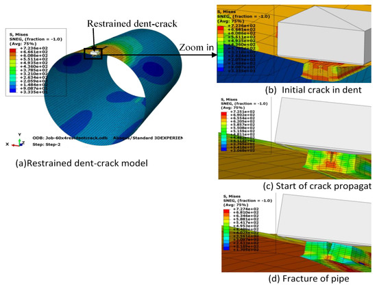
Figure 10.
Distribution of von Mises stress in pipe wall at various stages of propagation of a crack inside a restrained dent: (a) Model of pipe with restrained dent-crack; (b) Before applying pressure; (c) At start of crack propagation; (d) After fracture is complete.
Unrestrained dents rebound before the cracks begin to propagate through the wall, hence releasing elastic bending stresses. The crack is then free to open and propagate when the stress intensity at its tip exceeds material strength. The rebound action is prevented in restrained dent-crack defects. Therefore, the cracks are not free and require high internal pressure to open and begin propagation. The high internal pressure also plasticizes the pipe wall around the crack tip to the extent that the pipe cannot sustain significant additional pressure once crack propagation begins.
Table 3 shows the predicted burst pressure of specimens with various sizes of restrained dent-crack defects. All specimens with cracks of depth 0.2 t inside dents sustained pressures greater than the yield pressure, Py, of the pipe without fracturing. Crack length, dent depth, and denting pressures had no measurable effect on the burst pressure of the specimens, as they failed by plastic collapse. Releasing the indenter from the pipe surface with the pipe operating at MAOP did not cause crack propagation in the specimens (Table 4).
Table 3.
Burst pressure of pipes with restrained concentric dent-crack defect.
Table 4.
Effect of releasing indenter from pipe surface with pipe operating at maximum allowable internal pressure.
With a crack of depth 0.5t, burst pressures dropped with increasing crack length, dent depth, and denting pressure similar to the pipes with unrestrained dent-crack defects. However, burst pressure of specimens with restrained dents-cracks were generally higher than burst pressures of the corresponding specimens with unrestrained dent-cracks (Table 2) and plain cracked specimens (Table 5).
Table 5.
Burst pressure of specimens having plain cracks.
Restraining dents contribute in two ways to improve pipe resistance to fracture. First, compressive stresses from the restraint reduce stress triaxiality at the crack tip and secondly, they counteract hoop stresses from internal pressure. Therefore, high pressure is required to develop the fracture strain and propagate cracks in restrained dents.
Restrained dent-crack defects with crack lengths ≥ 100 mm inside dents of depth ≥ 6% OD formed at any pressure were problematic as they displayed susceptibility to unstable crack propagation in circumferential and longitudinal directions. Denting pipes at 0.8 Py propagated cracks of length ≥ 100 mm inside dents of depths ≥ 4% OD. Releasing the dent restraint at MAOP did not propagate cracks of length < 60 mm. Cracks of length > 60 mm propagated but only those with lengths > 100 mm and inside dents of depth ≥ 4% OD deep formed at 0.8 Py denting pressure propagated until the pipes burst when the dent restraint was released.
4. Conclusions
Burst pressure of pipeline with restrained and unrestrained concentric dent-crack defects was investigated in this study, considering the effect of varying crack geometry, dent depth, and denting pressure. Predicted burst pressures are compared with burst pressure of longitudinally cracked pipes without dents. Lastly, the effect of releasing the indenter from pipe surface when the pipe is operating at its maximum allowable operating pressure on crack propagation was assessed.
Specimens with unrestrained concentric dent-crack defects with dent depth of 2% OD formed at zero denting pressure had the same burst pressure as plain cracked specimens, but dent-crack defects were more injurious than plain cracks with increasing dent depth and denting pressures. A 0.2 t deep crack in dents formed at zero pressure was not problematic because the affected specimen sustained the MAOP of the pipe without the crack propagating, for crack lengths ≤ 200 mm and dent depths ≤ 6% OD.
Unrestrained dents of depth 6% OD formed at pressures > 0.3 Py, with cracks of depth ≥ 0.2 t, did not sustain the MAOP of the pipe. The cracks propagated at pressures lower than MAOP of the pipe, and risk of bursting at pressure lower than MAOP increased with crack length and denting pressure.
Specimens with restrained dent-crack defects had higher burst pressure than the corresponding specimens with unrestrained dent-crack defects and releasing the restraint at MAOP did not propagate 0.2 t deep cracks but propagated 0.5 t deep cracks. Risk of propagation and bursting increased with crack length, denting pressure, and dent depth. All cracks with length > 60 mm propagated but only those of length > 100 mm propagated until the pipes burst when dent restraint was released at MAOP of the pipe.
Increasing crack depth, crack length, and dent depth were more detrimental to pipe integrity than increasing denting pressure. But, deep dents (>4% OD) disproportionately increased the effect of the other defect parameters on pipeline integrity and burst pressure.
Pipelines with restrained concentric dent-crack defects are safe for service at maximum allowable operating pressure of the pipe if the restraints remain in position on the pipe surface.
Integrity of pipelines with unrestrained concentric dent-cracks vary with defect geometry. Affected pipelines retain significant strength and may be maintained in service with careful assessment.
Although only two crack depths were considered in this study, the results suggest that dent-crack defects are not too severe on integrity of pipelines subjected to monotonically increasing pressure. A study involving more crack depths and locations within dents other than the dent center (apex) is required for a broader understanding of the effect of dent-crack defects on the integrity of pipelines. Our future work will investigate more crack depths and the effect of cracks located in the flank of dents on burst pressure. Additionally, the fatigue life of pipelines with dent-crack defects, which has not been the focus of the present study, will be investigated.
Author Contributions
The authors have agreed upon the following credit statement for this manuscript. Conceptualization: A.O., Y.L., and S.A.; Methodology: A.O. and S.A.; Investigation: A.O. and S.A.; Formal Analysis: A.O., Y.L., and S.A.; Resources: S.A., N.Y.-G., M.K., and R.C.; Writing—original draft preparation: A.O. and Y.L.; Writing—review and editing: Y.L., S.A., R.C., and N.Y.-G.; Supervision: S.A.; Project administration: S.A.; Funding acquisition: S.A., N.Y.-G., R.C., and M.K. All authors have read and agreed to the published version of the manuscript.
Funding
The authors wish to acknowledge funding received from NSERC and Enbridge Pipelines Inc.
Conflicts of Interest
The authors declare no conflict of interest.
Disclaimer
Any information or data pertaining to Enbridge Employee Services Canada Inc., or its affiliates, contained in this paper was provided to the authors with the express permission of Enbridge Employee Services Canada Inc., or its affiliates. However, this paper is the work and opinion of the authors and is not to be interpreted as Enbridge Employee Services Canada Inc., or its affiliates’, position or procedure regarding matters referred to in this paper. Enbridge Employee Services Canada Inc. and its affiliates and their respective employees, officers, director, and agents shall not be liable for any claims for loss, damage, or costs, of any kind whatsoever, arising from the errors, inaccuracies, or incompleteness of the information and data contained in this paper or for any loss, damage, or costs that may arise from the use or interpretation of this paper.
References
- The American Society of Mechanical Engineers. Gas Transmission and Distribution Piping System: ASME Code for Pressure Piping, B31; ASME-B31.8; Revision to B31.8-1999; The American Society of Mechanical Engineers: New York, NY, USA, 2003. [Google Scholar]
- Ghaednia, H.; Das, S.; Wang, R.; Kania, R. Dependence of burst strength on crack length of a pipe with a dent-crack defect. J. Pipeline Syst. Eng. Pract. 2017, 8, 4016019. [Google Scholar] [CrossRef]
- Ghaednia, H.; Das, S.; Wang, R.; Kania, R. Effect of operating pressure and dent depth on burst strength of NPS30 line pipe with Dent-Crack defect. J. Offshore Mech. Arct. Eng. 2015, 137, 031402-8. [Google Scholar] [CrossRef]
- Ghaednia, H.; Das, S.; Wang, R.; Kania, R. Safe burst strength of a pipeline with dent-crack defect: Effect of crack depth and operating pressure. Eng. Fail. Anal. 2015, 55, 288–299. [Google Scholar] [CrossRef]
- Rafi, A.; Silva, J.; Kenno, S.; Das, S.; Kania, R.; Wang, R.Y. Strength of line pipe with dent and crack defect. In Proceedings of the 8th International Pipelines Conference, IPC 2010-31095, Calgary, AB, Canada, 27 September–1 October 2010. [Google Scholar]
- Bedairi, B.; Cronin, D.; Hosseini, A.; Plumtree, A. Failure prediction for crack-in corrosion defects in natural gas transmission pipelines. Int. J. Press. Vessel. Pip. 2012, 96, 90–99. [Google Scholar] [CrossRef]
- Vilkys, T.; Rudzinskas, V.; Prentkovskis, O.; Tretjakovas, J.; Višniakov, N.; Maruschak, P. Evaluation of failure pressure for gas pipelines with combined defects. Metals 2018, 8, 346. [Google Scholar] [CrossRef]
- Ronny, H.; Espen, B.; Lijana, D.O. Damage assessment of pipelines with dents and cracks, proposal for methodology for calculation of acceptable dimensions of a combination of crack, & dent in subsea pipelines. In Proceedings of the ASME 29th International Conference on Ocean, Offshore and Arctic Engineering, Shanghai, China, 6–11 June 2010. [Google Scholar]
- Lancaster, E.R.; Palmer, S.C. Burst pressures of pipes containing dents and gouges. Proc. Inst. Mech. Eng. Part E J. Process Mech. Eng. 1996, 210, 19–27. [Google Scholar] [CrossRef]
- Cosham, A.; Hopkins, P. The effect of dents in pipelines—Guidance in the pipeline defect assessment manual. Int. J. Press. Vessel. Pip. 2004, 81, 127–139. [Google Scholar] [CrossRef]
- Macdonald, K.A.; Cosham, A. Best practice for the assessment of defects in pipelines—Gouges and dents. J. Eng. Fail. Anal. 2005, 12, 720–745. [Google Scholar] [CrossRef]
- Orynyak, I.; Yakovleva, E.; Rozgonyuk, V. Application of the cheng-finnie method to the calculation of stress intensity factors in thin-walled pipes with long axial cracks with allowance for geometric nonlinearity. Strength Mater. 2007, 39, 455–465. [Google Scholar] [CrossRef]
- Bai, Y.; Song, R. Fracture assessment of dented pipes with cracks and reliability-based calibration of safety factor. Int. J. Press. Vessel. Pip. 1997, 74, 221–229. [Google Scholar] [CrossRef]
- Das, S.; Cheng, J.J.R.; Murray, D.W. Prediction of fracture in wrinkled energy pipelines subjected to cyclic deformations. Int. J. Offshore Polar Eng. 2007, 17, 205–212. [Google Scholar]
- Adeeb, S.M.; Horsley, D.J. A numerical procedure to establish a safe working pressure during excavation of a pipeline in a rock ditch. Int. J. Press. Vessel. Pip. 2006, 83, 488–497. [Google Scholar] [CrossRef]
- Tian, X.; Zhang, H. Failure criterion of buried pipelines with dent and scratch defects. J. Eng. Fail. Anal. 2017, 80, 278–289. [Google Scholar] [CrossRef]
- Kainat, M.; Langer, D.; Hassanien, S. Do we need a safe excavation pressure for dented pipelines: How should it be defined? In Proceedings of the 12th International Pipelines Conference, Ipc2018-78376, Calgary, AB, Canada, 24–28 September 2018. [Google Scholar]
- Rosenfield, M.J.; Pepper, J.W.; Lewis, K. Basis of the New Criteria in ASME B31.8 for Prioritization, & Repair of Mechanical Damage. Int. Pipeline Conf. 2002, 36207, 647–658. [Google Scholar]
- Okodi, A.; Lin, M.; Yoosef-Ghodsi, N.; Kainat, M.; Hassanien, S.; Adeeb, S. Crack propagation and burst pressure of longitudinally cracked pipeline using extended finite element method. Int. J. Press. Vessel. Pip. 2020, 184, 104115. [Google Scholar] [CrossRef]
- Dassault Systèmes. Abaqus Documentation; Dassault Systèmes: Velizy-Villacoublay, France, 2016. [Google Scholar]
- Melenk, J.M.; Babuska, I. The partition of unity finite element method: Basic theory and applications. Comput. Methods Appl. Mech. Eng. 1996, 139, 289–314. [Google Scholar] [CrossRef]
- Moes, N.; Dolbow, J.; Belytschko, T. A finite element method for crack growth without remeshing. Int. J. Numer. Methods Eng. 1999, 46, 131–150. [Google Scholar] [CrossRef]
- Fries, T.P.; Belytschko, T. The extended/generalized finite element method: An overview of the method and its applications. Int. J. Numer. Methods Eng. 2000, 84, 253–304. [Google Scholar] [CrossRef]
- Liu, X.B.; Zhang, H.; Han, Y.; Xia, M.; Ji, Y. Numerical and Experimental study on critical crack tip opening displacement of X80 pipeline steel. Mechanics 2017, 23, 204–208. [Google Scholar] [CrossRef]
- Li, H.; Chandra, N. Analysis of crack growth and crack-tip plasticity in ductile materials using cohesive zone models. Int. J. Plast. 2003, 19, 849–882. [Google Scholar] [CrossRef]
- Cravero, S.; Ruggeri, C. Structural Integrity Analysis of Axially Cracked Pipelines Using Conventional and Constraint-Modified Failure Assessment Diagrams. Int. J. Press. Vessel. Pip. 2006, 83, 607–617. [Google Scholar] [CrossRef]


Publisher’s Note: MDPI stays neutral with regard to jurisdictional claims in published maps and institutional affiliations. |
© 2020 by the authors. Licensee MDPI, Basel, Switzerland. This article is an open access article distributed under the terms and conditions of the Creative Commons Attribution (CC BY) license (http://creativecommons.org/licenses/by/4.0/).