1. Introduction
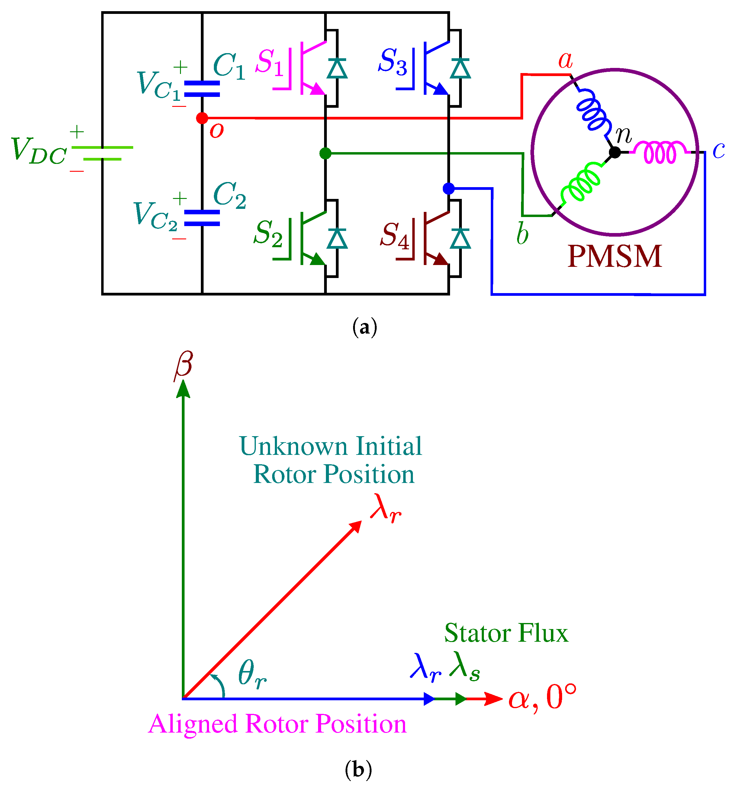
In many applications such as in light electric vehicles and consumer products, low power is desired. The utilization of a cost-effective three-phase inverter is crucial to decrease the cost of the drive system. This can be achieved by eliminating two semi-conductors in the inverter topology making it four-switch three-phase inverter, as shown in
Figure 1a [
1,
2,
3,
4]. For sensorless operations where the initial rotor position detection is not available or starting from an unknown rotor position is not possible, aligning or locking the rotor to a predetermined position is inevitable for proper starting of PMSM [
5]. Additionally, for sensored operation of PMSM drives where incremental optical encoder is used as the position sensor, the initial rotor position is not known, therefore the alignment procedure is mandatory [
6]. The precise rotor position must be identified before starting the motor and after the DC-link is at full capacity.
The PMSM has to be energized by a selected voltage vector or sequence of voltage vectors to align the rotor to the predefined position. In studies using sensorless control and incremental encoders in sensor based AC drives, methods for determination of initial rotor position and alignment to zero angle have not been investigated for the FSTP inverter. Locking the rotor to a known position (especially zero angle), as shown in
Figure 1b at start-up is easily performed in classical six-switch three-phase (SSTP) inverters using conventional techniques, however zero angle alignment with classical methods do not work in case of an FSTP inverter due to the fact that the DC-link voltage is at full capacity and one phase (phase
a which is set to align with zero position and
d-axis rotor flux linkage vector) of the PMSM is mounted to the midpoint of the split capacitors in the DC-link, as shown
Figure 1a such that all the four non-zero voltage vectors aligned with the
–axes. Therefore, simplified space vector pulse width modulation (SVPWM) generation in FSTP based inverter is achieved [
7,
8,
9].
In the classical rotor alignment procedure of the PMSM drive with vector control scheme, enough
d-axis constant current is injected to overcome the load, inertia and friction in the vector controlled scheme whilst
q-axis current reference is set to zero with zero position input applied to the co-ordinate transformations such as Park and inverse Park prior to startup, therefore the rotor flux is aligned with the stator flux which is set to zero degree position [
10]. The main disadvantages of such conventional techniques are that they are mainly dependent on PI regulators and can be easily applicable to six-switch inverter based PMSM drives without causing severe degradation at the startup procedure. Moreover, with the classical rotor position alignment method, dynamic performance strongly relies on the bandwidth of the current control loop and the parameters of the
d- and
q-axes current regulators. High and low frequency pulse signal injection methods are investigated for the sensorless control of PM machines in classical six-switch three-phase inverters [
11,
12,
13]. However, these studies are intended to estimation of initial rotor position. In the FSTP inverter fed PMSM drive, classical alignment procedure with
d-axis current regulator with zero position applied to the co-ordinate transformations that is used for three-phase six-switch (SSTP) inverter generates improper voltage vectors that does not perform alignment to zero angle when phase
a (
d-axis zero angle position) is attached to the mid-point of the split capacitors.
In [
14], a simple sector determination scheme for a normalized SVPWM is proposed for the FSTP inverter without voltage or position sensors such that the complex calculations are eliminated in the controller. Although, the sector determination algorithm is developed for SVPWM, no discussion has been given on obtaining a zero angle initial rotor position alignment. Current and torque ripple minimization incorporating SVPWM are also reported in [
8] for FSTP inverters where the compensation techniques are employed for PMSM drives to reduce the unbalancing and current and torque distortion in FSTP inverters. However, the main focus in this work is to reduce the oscillation observed in current and torque waveforms due to the nature of FSTP inverters. Therefore, in this study, no details have been given on the encoder type or about the initial rotor position detection methodology. A study in the literature given in [
15] discusses the initial rotor position alignment issue of the FSTP inverters. The solution to this problem explained in [
8], which is locking the rotor with line-to-line voltage is possible but does not acquire zero angle alignment.
In this paper, the proper rotor position alignment methodology to a predetermined zero angle position is developed for the FSTP driven PMSM drive. It is shown that the rotor position can be aligned to zero electrical degree position properly using low-frequency d-axis synchronous reference frame voltage in which the desired constant virtual zero position is applied to the co-ordinate transformation (inverse Park transformation) without using classical closed loop dq–axes current regulators. Thus, correct zero position alignment is achieved in a short amount of time for the FSTP inverter based PMSM drive at start-up. The proposed initial zero angle rotor position alignment method is simple and therefore is eligible for real-time implementation of cost effective four-switch PMSM drives.
2. Definition of Problem and the Proposed Signal Injection-Based Initial Zero Angle Rotor Position Alignment Method for FSTP Inverter
The simplest approach to align/lock the rotor to a known initial position in the FSTP inverter fed PMSM drive before starting is performed by applying a constant voltage vector to the stator phases to produce a stationary magnetic field and the rotor aligns itself naturally onto this stator field. However, one phase (phase a) is mounted to the mid-point of the capacitors for the FSTP topology, therefore under constant voltage input no current will flow through phase a which does not allow aligning the rotor position to the desired zero angle.
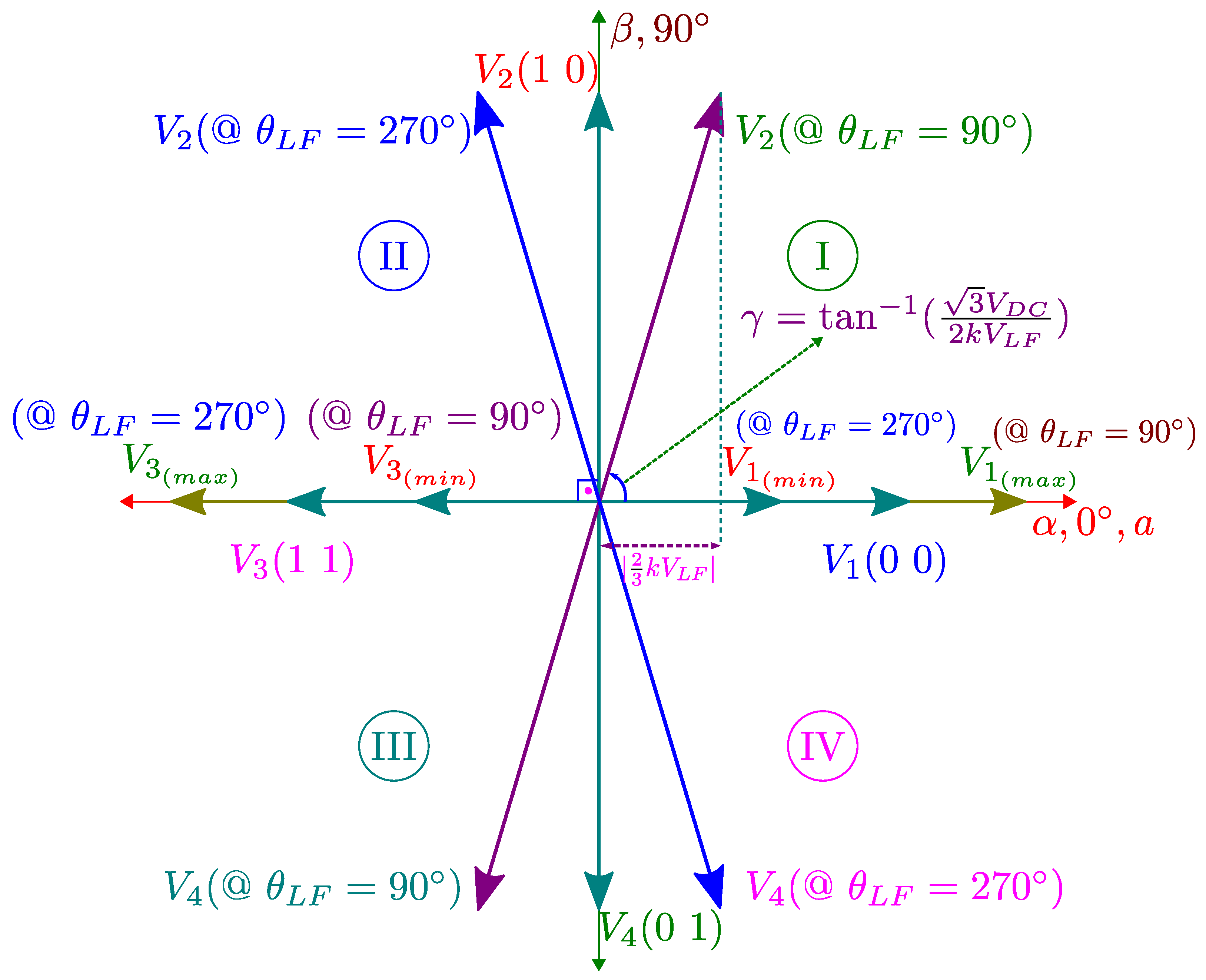
Fluctuations in the two capacitor voltages
and
exist that produce a deviation of the non-zero voltage vectors from their previous position, as shown in
Figure 2. This can easily be overcome in the SSTP inverter where all phases can be controlled by the corresponding switches on each of the inverter legs. In the proposed alignment scheme at the startup process for FSTP inverter based PMSM drives, the pulse width modulated low-frequency
d-axis voltage reference signal is injected to phase
a through phase
b and
c allowing current to be flown in phase
a and therefore proper rotor position alignment to zero angle is achieved.
3. Mathematical Analysis of the Proposed Zero Angle Initial Rotor Position Alignment Scheme
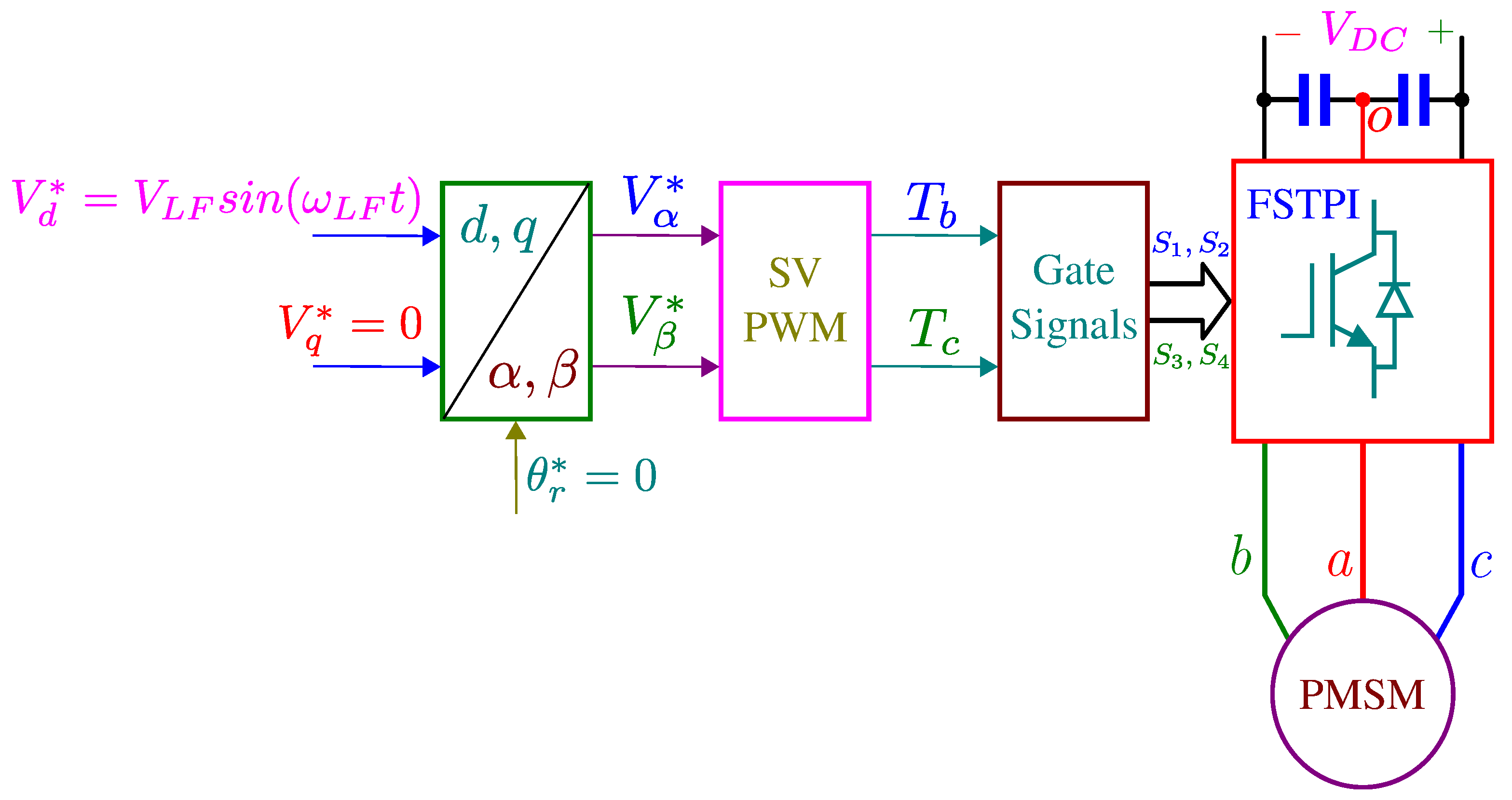
For proper zero angle rotor position alignment in FSTP inverter based PMSM drive, open-loop voltage control with
d-axis low-frequency (
Hz) reference signal
is injected along with
to the drive scheme, as shown in
Figure 3. By injecting the fluctuated voltage signal to the
d-axis, constant
voltage with fluctuated AC components are generated on the upper and lower capacitor voltages given by
where
k is the resultant AC voltage amplitude constant
in the DC-link capacitors due to the motor parameters, capacitor values, and the injected signal frequency.
is the equivalent impedance when phase
a is energized and phase
b and
c are shorted under voltage signal injection. As a result, current flows in phase
a and therefore alignment to zero position is achieved. The magnitude of
and injected signal frequency
determine the time elapse to lock the rotor to the desired zero angle position. Using Equation (
1), the four active voltage vectors under low-frequency
d-axis signal injection case are tabulated in
Table 1 and
Table 2.
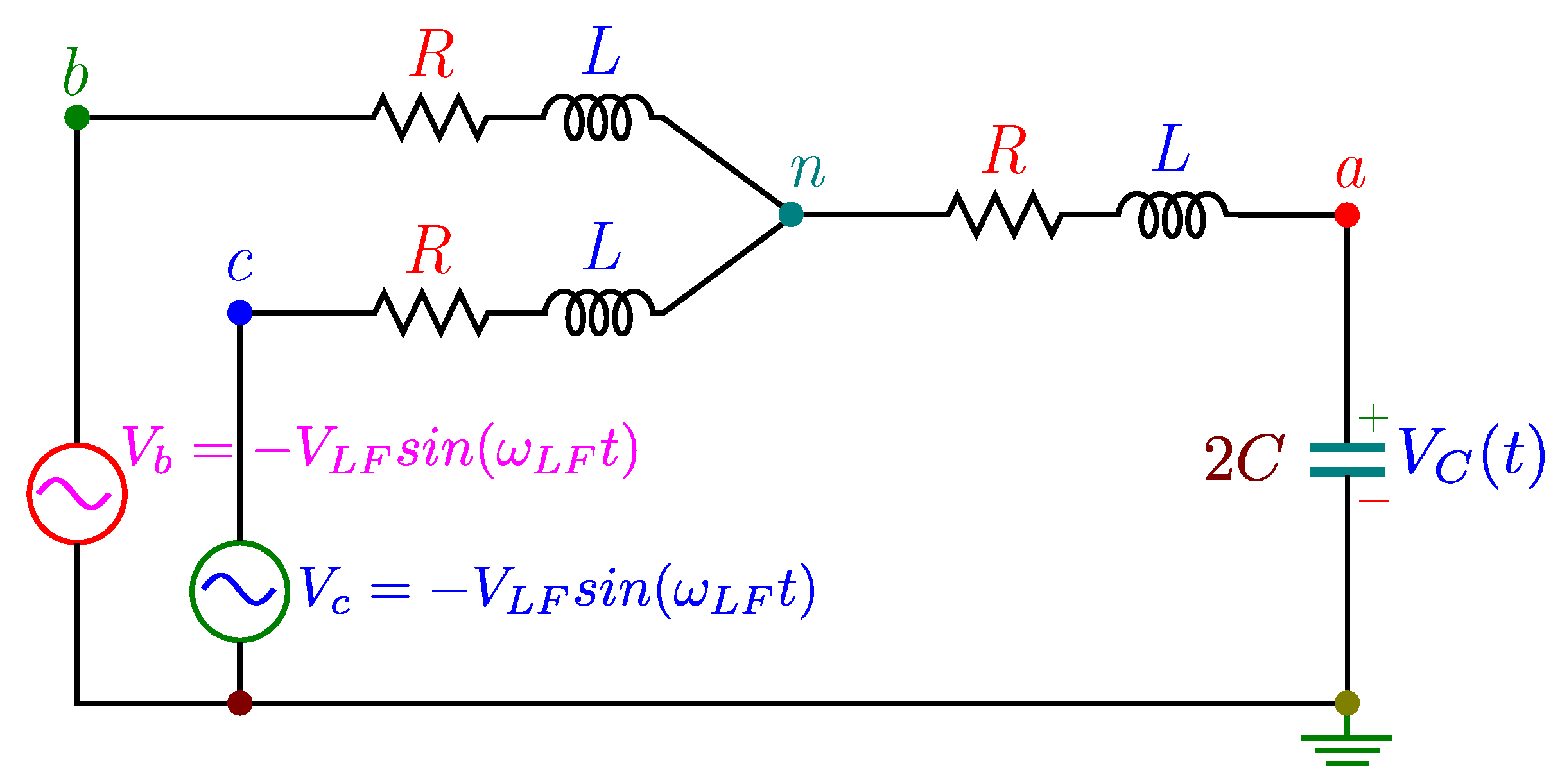
Analysis of Inverter Capacitor Effect
Since the circuit given in
Figure 4 has stator resistances, damping occurs in the system. Resonance will naturally be determined by the damping of the circuit irrespective of the applied low-frequency AC signal. If the circuit is underdamped, the system resonates otherwise the circuit operates as overdamped without resonance. The circuit in
Figure 4 has a damping factor calculated as
Since the damping factor
= 2.4042 is greater than 1, the system behaves as overdamped without oscillation. The critically damped condition of the circuit occurs at
where
is stator resistance,
is stator inductance and
C =
=
= 380
F considering the electrical machine parameters are constant. The Semikron SEMITEACH
TM inverter that has been used in this system has two 2200
F capacitors. Since the calculated damping factor in Equation (
2) is greater than 1 with the already built-in capacitors in the inverter, the system acts as overdamped without oscillation.
4. Determination of Constant
Applying inverse Park transformation in
Figure 3 of the open-loop voltage control of FSTP inverter based PMSM drive, reference
–axes voltages are obtained as
Assuming
electrical position occurs at the border of Sector I and IV, duty ratios
and
in the SVPWM calculations can be derived as
where
and
. Actual leveled duty cycles are expressed as
Therefore,
b– and
c–axes LFS injection based voltages applied to the motor terminals are given as
An equivalent circuit of the zero angle alignment of PMSM drives with LFS injection based on an FSTP inverter can be drawn in terms of inverter and motor parameters, as shown in
Figure 4 where
L and
R are the motor inductance and resistance.
C is the capacitor of the FSTP inverter. DC voltage ripples on capacitors can be obtained by solving the circuit illustrated in
Figure 4. The amplitude of the equivalent impedance of
Figure 4 can be derived as
5. Implementation and Experimental Results
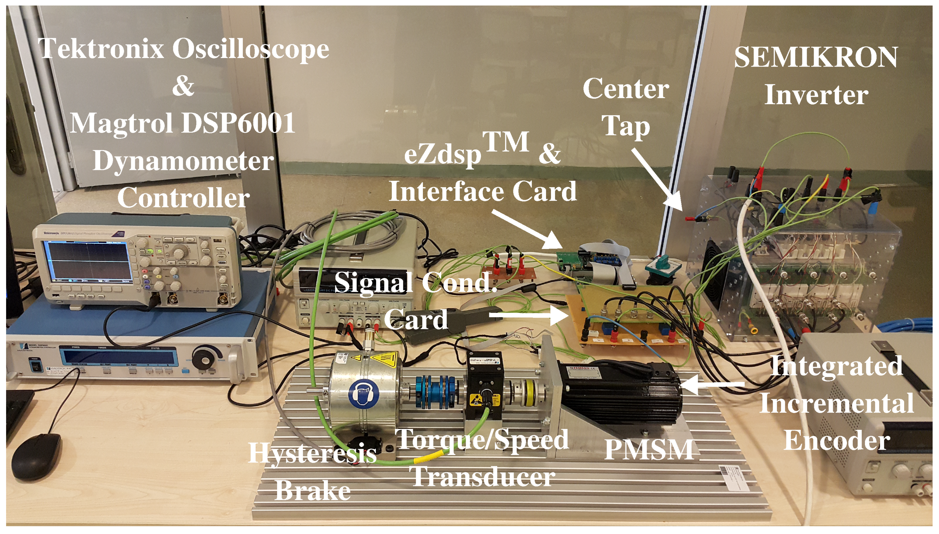
To validate the feasibility of the proposed scheme, an experimental platform of the FSTP inverter for PMSM drive is set up which is shown in
Figure 5. Comparative experimental studies of the proposed smooth initial rotor position alignment method and the classical method have been conducted on a 1 kW FSTP inverter fed PMSM drive. The stator resistance and inductance of the PMSM are 3.4
and 3.3 mH, respectively. The rotor magnetic flux linkage is 0.095 Wb. The DC-link voltage measurements are performed by Tektronix TPP0200 model passive voltage probes with 300 V max. range and up to 200 MHz bandwidth. The voltage probes are used with the voltage amplifiers. The current probe used in the system is Fluke 80i-110s with ±(3% + 50 mA) accuracy at 10 A and ±100 A range. Rotor position and speed are obtained by HEDSS ICU4809 incremental encoder with 2500 ppr with up to 120 kHz response frequency.
Figure 6,
Figure 7,
Figure 8 and
Figure 9 illustrate the experimental results of the mechanical rotor positions and DC-link capacitor voltages using conventional and the proposed methods under fan type load, respectively.
Figure 10 and
Figure 11 represent phase
a current and mechanical rotor speed using the proposed method under
400 V with
and
are 2200
F, respectively. In
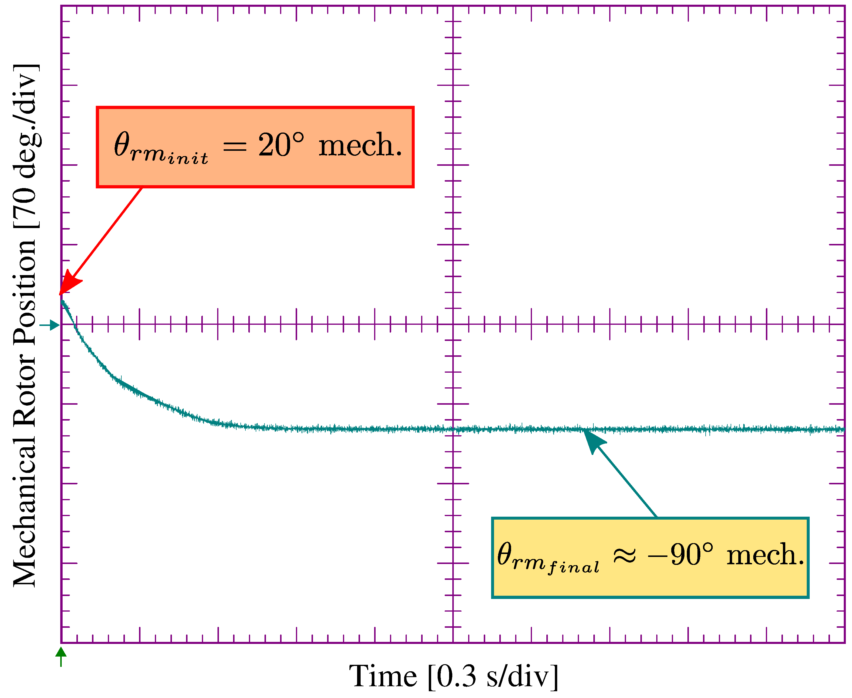
Figure 6, classical rotor alignment with the proper constant
d-axis voltage value using virtual zero angle is applied as a reference with
q-axis voltage is set to zero. The rotor is deviated too much from the desired zero angle from the initial position of 20 mechanical degrees. Its final position is around −90 mechanical degrees, as shown in
Figure 6.
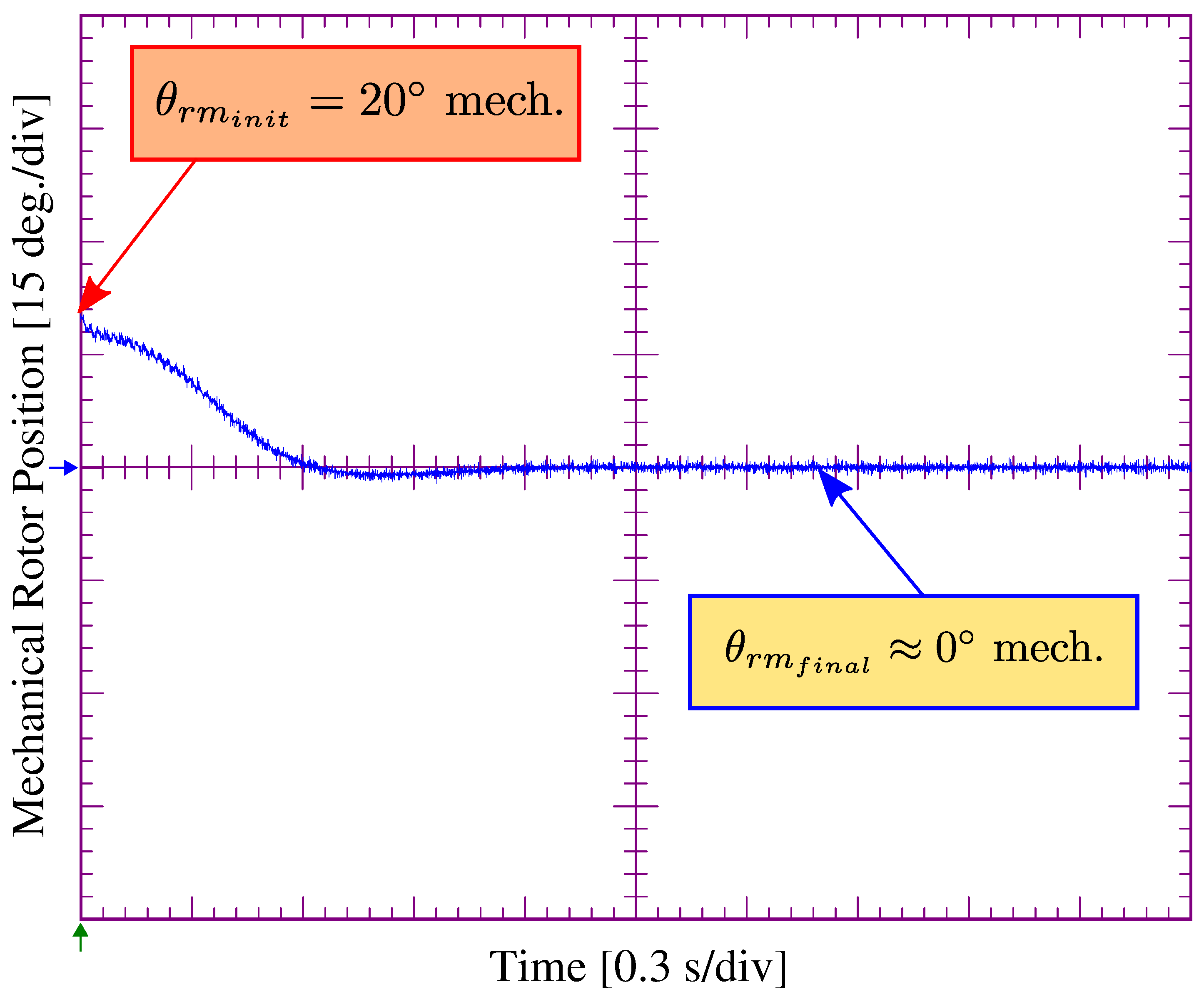
It is seen in
Figure 7 that under
50 Hz LFS injection with 0.25 pu
d-axis voltage amplitude reference, proper zero angle alignment is successfully achieved. Initial rotor position is set to 20 mechanical degrees. After 1.2 s, the rotor locks to the zero mechanical degree position with the proposed method as opposed to the classical one in which the alignment procedure to zero angle is not successful, as shown in
Figure 6. The rotor is aligned to a negative position using the classical alignment method. Since only DC capacitor voltages exist in the classical zero angle alignment method, no current flows through the phase which is mounted to the center point of the capacitors. Therefore, the alignment procedure is unsuccessful.
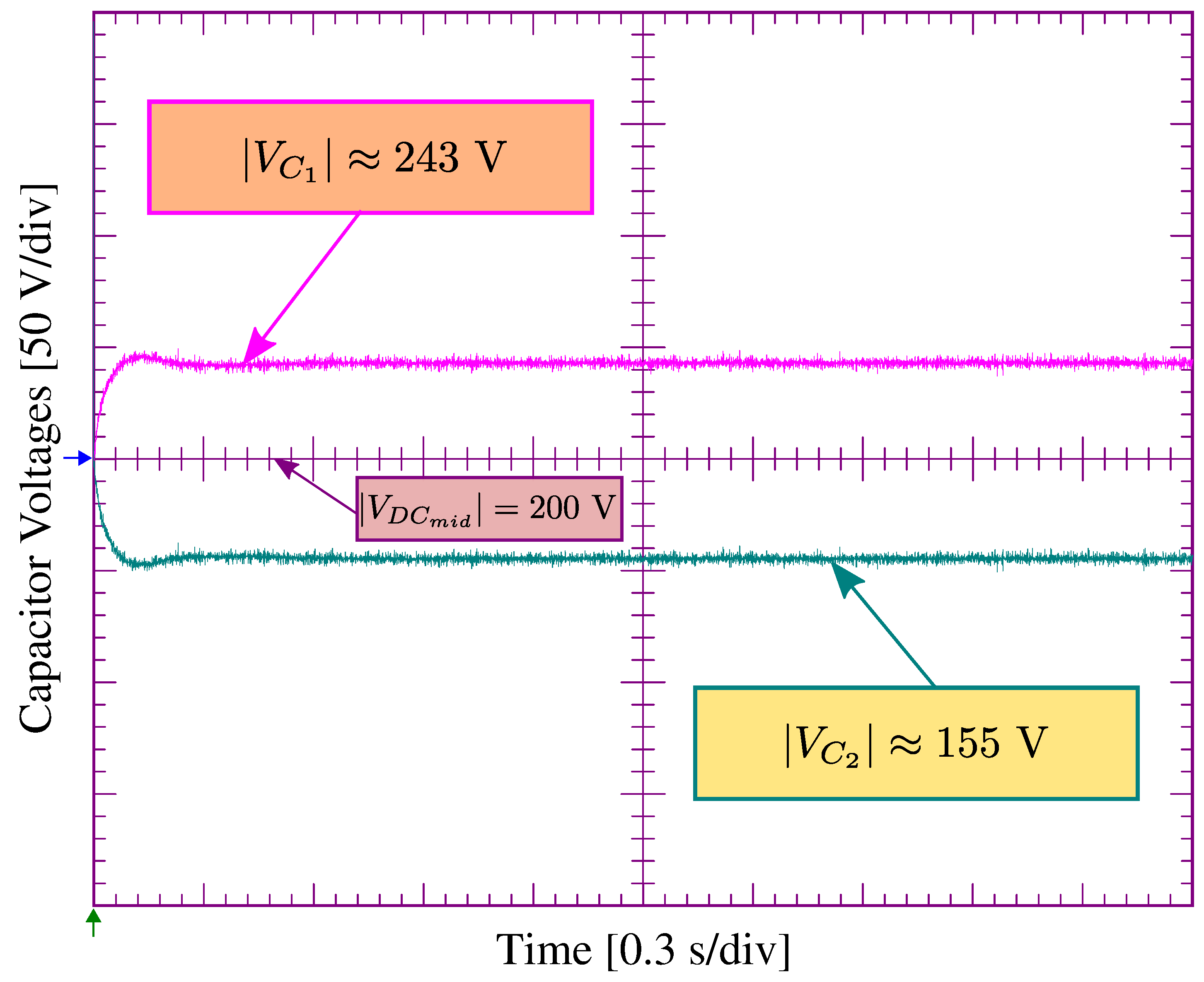
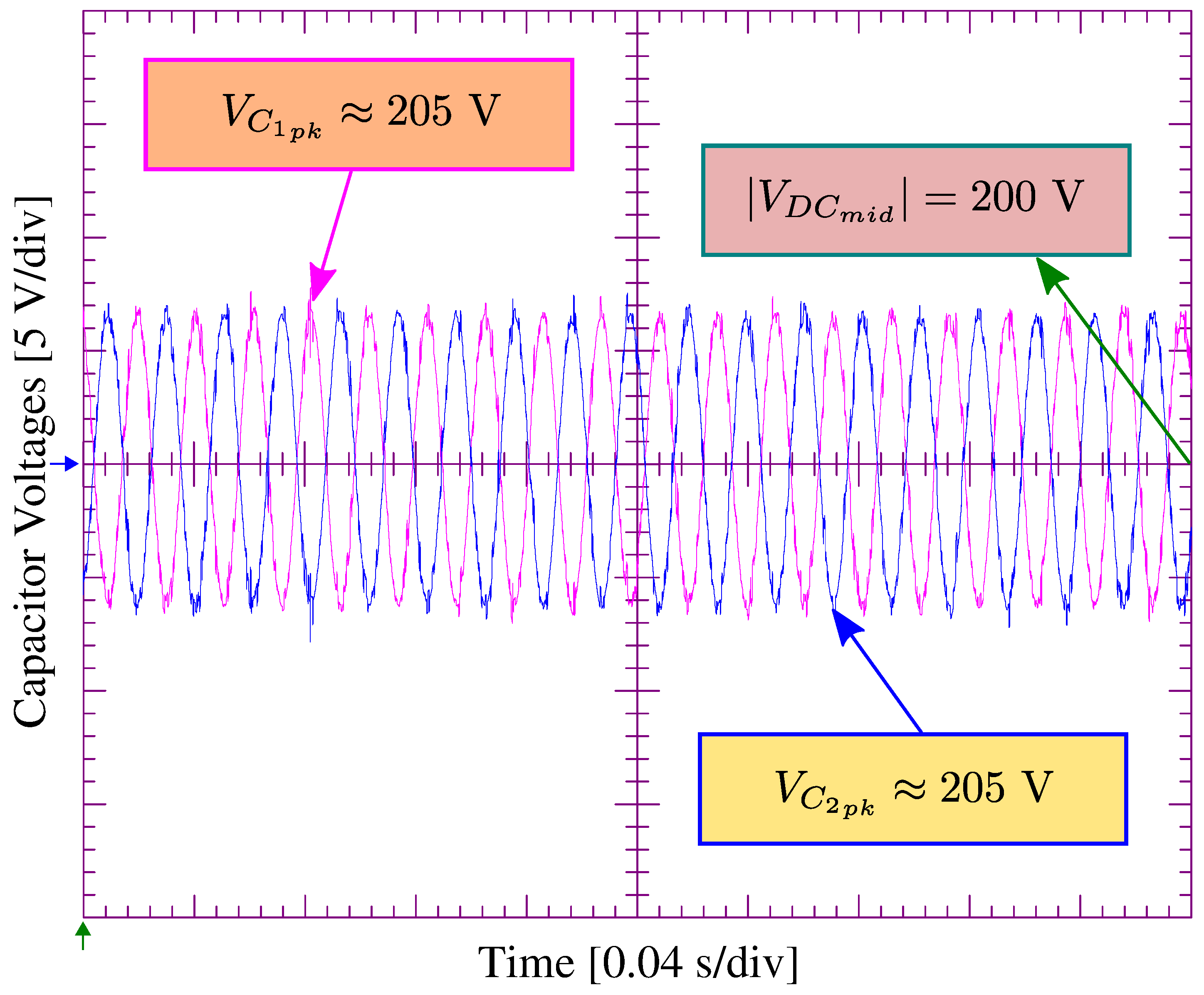
With the proposed scheme, LF signal allows fluctuation on the DC-link offset voltage, as shown in
Figure 9 enabling current flowing through the center tap connected to phase
a which results in proper zero rotor angle alignment. The amplitude of the fluctuated DC-link voltages matches with the
k value that is theoretically calculated in Equation (
10). The frequency of oscillated DC-link voltages equals to the injected LF signal frequency.
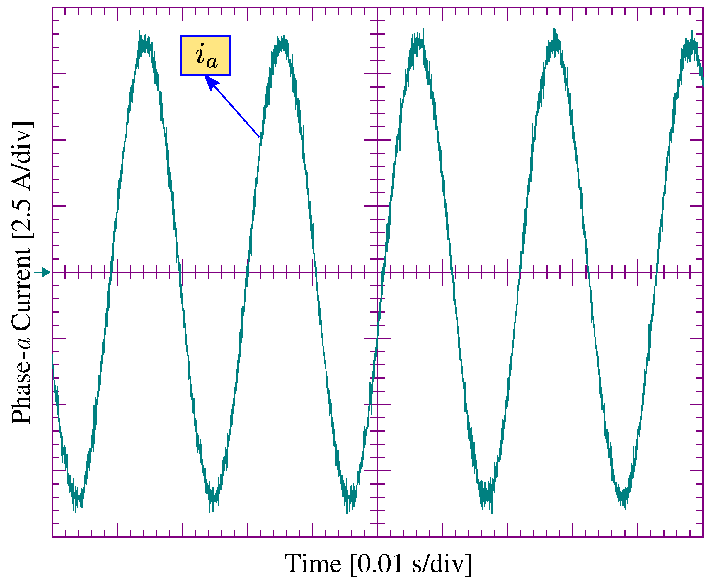
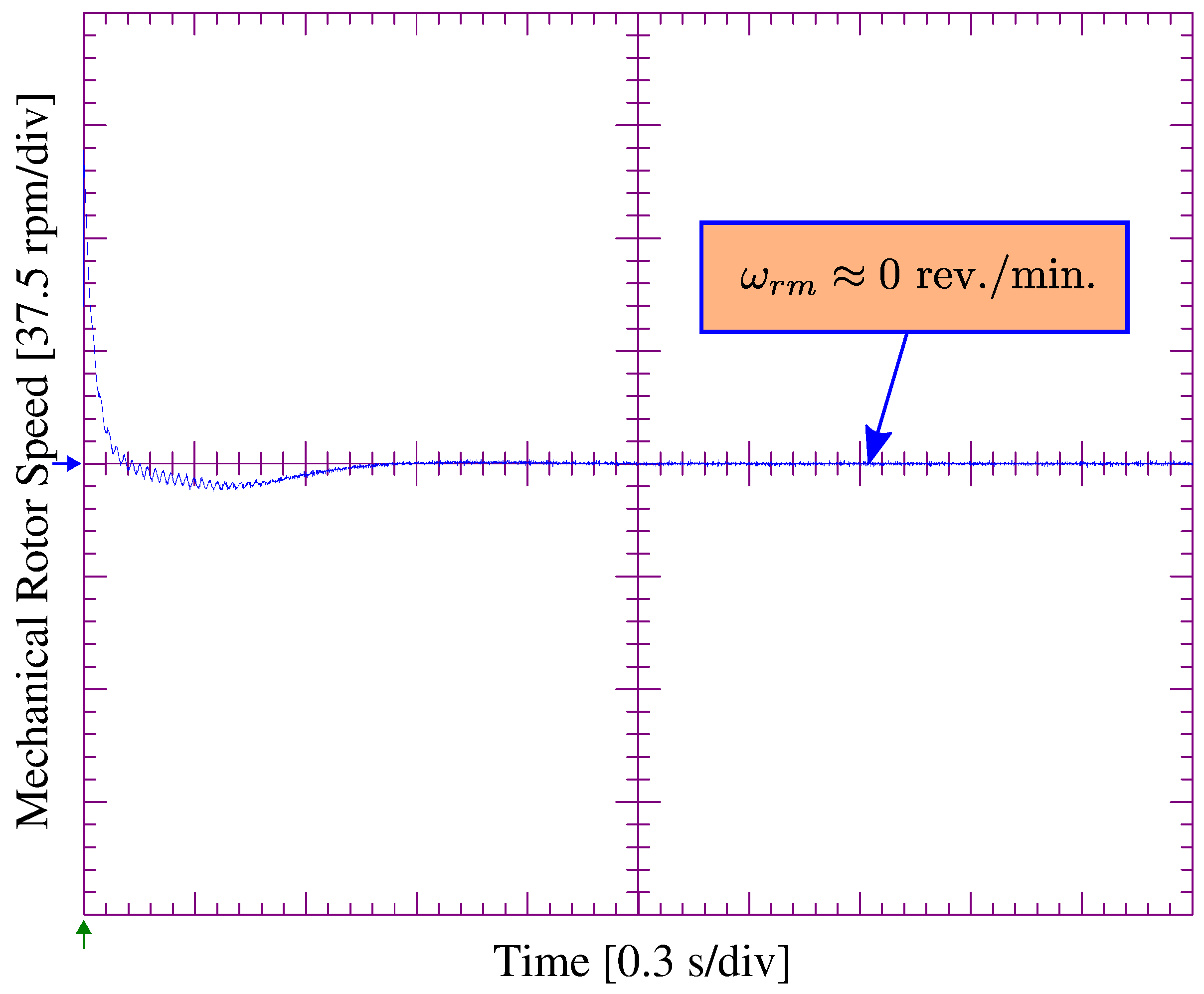
Steady-state phase
a current waveform is given in
Figure 10. It is seen that no low frequency fluctuations are reported on the phase current. This will not cause mechanical oscillation in the motor when the rotor is locked with the zero angle. When the rotor is aligned to the proper zero position, the speed of the rotor is dropped to zero as well at the same time with the position, as shown in
Figure 11.
The sensitivity analysis based on the input applied voltage amplitude
and the injected signal frequency
versus the time duration of the alignment are depicted in the
Table 3. It is observed in the sensitivity analysis that when the
ratios is around 0.005, the faster alignment is achieved. The motor current increases when the input voltage amplitude is selected higher than 0.25 pu which is selected to be the optimum voltage amplitude. If the inertia and/or load of the system are higher than expected, a proper offset can be added as a bias to the injected signal to achieve zero angle alignment. Since the application of this method is only used for the initial alignment procedure, it will only run for a few seconds.
As can be seen in
Table 3 that higher
values with proper injected frequency (close to the motor nominal operating frequency) considering the
ratio generate more
at the DC-link and the alignment time is reduced. The optimum
amplitude is selected to be 25% of the nominal voltage at 50 Hz (nominal operating frequency of the motor).
The proposed zero angle rotor position alignment method at start-up could be used in applications such as centrifugal pump, fan and blower where initially light load or no-load occur including permanent magnet synchronous generators that are mounted on small scale wind turbines. Since the basis of the proposed method is an open-loop, alignment time depends on the system inertia, applied voltage, and the frequency of the injected signal. After the alignment procedure is completed, switching to the closed-loop control algorithm is enabled which drives the four-switch PMSM system. If the desired zero rotor position has not been achieved while the speed is not close to zero for a certain amount of time, the applied frequency is lowered properly to speed up the alignment procedure.


