Article

Simple Ventilators for Emergency Use Based on Bag-Valve Pressing Systems: Lessons Learned and Future Steps

by
Enrique Castro-Camus
1,*,
Jan Ornik
2,
Cornelius Mach
2,
Goretti Hernandez-Cardoso
1,
Bhushan Savalia
2,
Jochen Taiber
2,
Armando Ruiz-Marquez
1,
Karl Kesper
3,
Srumika Konde
2,
Caroline Sommer
2,
Julian Wiener
2,
David Geisel
2,
Franziska Hüppe
2,
Gunter Kräling
4,
Peter Mross
5,
Johnny Nguyen
2,
Thomas Wiesmann
6,
Björn Beutel
7,8 and
Martin Koch
2
1
Centro de Investigaciones en Optica, A.C., Loma del Bosque 115, Lomas del Campestre, Leon, Guanajuato 37150, Mexico
2
Faculty of Physics and Material Sciences Center, Philipps-Universität Marburg, 35037 Marburg, Germany
3
Abteilung für Innere Medizin, Schlafmedizinisches Zentrum, Universitätsklinikum Gießen und Marburg GmbH, Baldingerstraße 1, 35043 Marburg, Germany
4
Department of Medical Technology, Universitätsklinikum Gießen und Marburg GmbH, 35043 Marburg, Germany
5
Department of Neurology, Universitätsklinikum Gießen und Marburg GmbH, 35043 Marburg, Germany
6
Department of Anaesthesiology and Intensive Care Medicine, University Hospital Marburg, Philipps University of Marburg, Baldingerstraße, 35033 Marburg, Germany
7
Department of Medicine, Pulmonary and Critical Care Medicine, University Medical Center Gießen und Marburg, Philipps University Marburg, 35037 Marburg, Germany
8
The German Center of Lung Research (DZL), Baldingerstrasse, 35043 Marburg, Germany
*
Author to whom correspondence should be addressed.
Appl. Sci. 2020, 10(20), 7229; https://doi.org/10.3390/app10207229
Submission received: 3 September 2020 / Revised: 29 September 2020 / Accepted: 5 October 2020 / Published: 16 October 2020
(This article belongs to the Section Applied Physics General)

Abstract

:
As part of a plethora of global efforts to minimize the negative effects of the SARS-CoV2 (COVID-19) pandemic, we developed two different mechanisms that, after further development, could potentially be of use in the future in order to increase the capacity of ventilators with low-cost devices based on single-use-bag-valve mask systems. We describe the concept behind the devices and report a characterization of them. Finally, we make a description of the solved and unsolved challenges and propose a series of measures in order to better cope with future contingencies.

1. Introduction

The international health crisis caused by the rapid propagation of the SARS-CoV2 (COVID-19) has triggered an unprecedented type of collaborative and distributed development worldwide. From professional scientists, physicians and engineers in universities, research institutions and companies to individuals with home-based electronics and mechanics building capabilities have started intensive brainstorming, prototyping, re-engineering and testing of potential solutions to multiple aspects of the pandemic.
Taking into account the experience gained in China and Italy, two of the earliest and most affected countries by the pandemic so far, it is clear that a key piece of equipment required at hospitals are mechanical ventilators and that the number of available ventilators is insufficient with regard to the potential numbers needed in most countries worldwide [1]. On 13 March 2020, we decided to start an emergency project to develop and evaluate the potential of a platform for low-cost, easy-to-build ventilators to cope with the potential shortage of ventilators worldwide. During the following days, an interdisciplinary group was formed including people with backgrounds in physics, engineering, informatics, medicine, etc. to shape up ideas. Quickly, two approaches were chosen, prototypes started to be built, tested and optimized for performance and reliability. In this contribution, we present two ventilator prototypes of the most basic approach that are based on the use of a bag-valve manual ventilator.
The design framework shown here is made to be a low cost design, easy modification of widespread standard components, or at least easy to manufacture and basic ventilator capacity. In addition, we enumerate challenges pending to be solved for this concept to be converted into a real solution. It is worth mentioning that although we have tried to include as many of the options and to meet characteristics similar to a professional mechanical ventilator, our objective was to build a simplified, easy- and economical-to-build apparatus that, when fully developed, could potentially be of benefit to patients in need for mechanical ventilation in a circumstance in which no other option can be offered. We also want to make a clear statement that the devices presented here:
  • Have not been approved for use by any health regulatory agency or homologous institution.
  • Have not been tested on humans or other animals, and that all tests have been carried out with mechanical and electronic equipment only. No clinical or preclinical trials have been conducted or approved up to the date of this publication.
  • We strongly discourage any attempt to use the devices presented here on humans. Its replication should only be for the purpose of further investigation and development.
Manually pumped ventilators have been used in the past to cope with epidemic-related patient surges [2]. It is worth noting that pushing mechanisms for a bag-valve ventilator is an approach that has been pursued by various groups around the world both in the past, mostly as an academic exercise [3,4,5]. Yet, in recent days many groups around the world have taken this concept as a possibility to cope with the current crisis [6,7,8,9,10]. It is worth mentioning that our designs might have similarities and face similar deficiencies to other bag-valve pushing mechanisms. For some of those developments detailed construction schematics and other detailed information have been made available to the public.

2. Design Considerations

While the use of mechanical ventilation is a clinical practice that is normally only used on patients that require it as a life-sustaining measure, inappropriate ventilation of a patient could result in damage to the lungs that would also be life-threatening [11,12,13]. The breathing process might seem a relatively simple one at first glance. To first approximation it is not very different to inflating and deflating a balloon, however, that simplistic view is what physicists would call a spherical-cow-approximation. There are a number of subtleties that make respiration more complex. In the following, we provide a brief description of the breathing process based on [14]. Under normal circumstances, inhalation is driven by the unconscious motion of a series of muscles, mainly the diaphragm as the key muscle together with different other muscle groups of the chest wall, that increase the volume of the thoracic cavity. This leads to a decrease of the pressure in the lungs which, at its time, results in the flow of fresh air into the lungs through the airway. The subsequent relaxation of said muscles increases the pressure in the lungs that produces the exhalation. Therefore inhalation is usually produced by “negative” thoracic pressure, while exhalation is produced by “positive” thoracic pressure. When mechanical ventilation is applied, usually through an endotracheal tube, the inhalation is no longer driven by negative pressure produced by the patient, but by positive pressure provided by the ventilator that “forces” air into lungs, this is a complete game-changer in many senses. For instance, natural “negative” pressure inspiration cannot over inflate the lungs and its internal ramified structures, the alveoli, which can potentially be damaged by overpressure when “positive” pressure is applied. This could lead to damage of the lung, which is usually already compromised by the underlying condition, such as pneumonia caused by COVID-19. Therefore, the volume per inspiration (tidal volume) and the appropriate pressures across the breathing cycle must be limited.
Unlike healthy subjects, who maintain a small volume of air in the lungs once the exhalation is over, critical patients in some cases produce a full exhalation. This causes the fluids that are in the lung to completely fill all the cavities, which means that it is more difficult to inflate the lung again in the following breath cycle, and making it more prone to injury by the mechanical ventilation. Therefore, a minimal positive pressure (positive end-expiratory pressure—PEEP) should be maintained in the lung at the end of the expiration in order to prevent the collapse of the lungs. It is worth mentioning that bag-valve resuscitators are single-use-products, thus, for each new patient, a new resuscitator is needed. Yet, hygienic standards are easy to follow, as the two mechanism prototypes themselves are not part of the pneumatic system itself. In addition, a connecting hose between the bag-valve system and the mask or endotracheal tube will be needed, which is normally not used in manual resuscitation. The total volume of that hose has to be significantly smaller than the tidal volume pumped in order to ensure appropriate exhaustion of the exhaled CO 2 to the atmosphere.
In addition to the purely pneumatic considerations, there are other aspects to be taken into account. For instance, forcing air into the lungs of a patient at a rate determined by the ventilator instead of the natural rhythm determined by the patient is extremely uncomfortable and requires deep sedation, which might complicate other aspects of the progress evaluation and treatment of the patient. Hence, a feedback mechanism, usually by pressure or flow, is desirable in order to trigger the breath cycle of the ventilator and thus improve the patient–ventilator synchrony. Furthermore, the gas used for ventilation should be enriched in oxygen content (FiO 2 ) since the lung capacity of the patient is diminished, and ideally the gas mixture should be humidified and warmed-up since the endotracheal tube bypasses the upper part of the airway (nose and pharynx), which usually performs these two functions.
During the four weeks that the prototyping process took in our group, we tried to incorporate as many of the desirable characteristics as possible to our prototypes. However, each degree of sophistication increases the cost of the device, the fabrication time and most importantly, the potential failure points. In the face of the contingency, careful reliability tests cannot be thoroughly performed for appropriately long periods. In Table 1 the typical setting parameters for a mechanical ventilator are shown [15].

3. Results

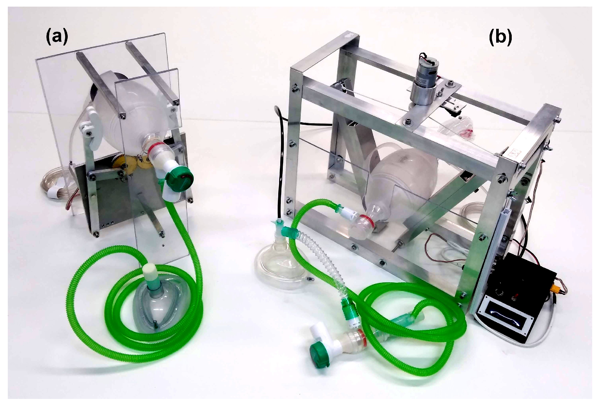
3.1. Prototype 1 (Contingence Life-Support Air Pressure Emergency Respirator—CLAPER)

The first approach was the construction of a bag-valve pusher that would be able to operate in continuous mode without the requirement of digital control, at least for a first simplified version, even if it did not meet all the ideal requirements. The system consists of a motor that drives a small gear, which at its time drives two larger gears coupled to each other in order for them to move synchronously but in opposite directions. The two gears have an additional eccentric axis that is used to move a coupling rod each, which moves an oscillatory arm which is fixed at one end to the baseplate of the mechanical system. A convex piece is attached to the other end of the arm, which is used to press the bag-valve at regular intervals. The position of the fixed point of the arm can be varied and this provides the user with control over the tidal volume (see the methods section). It is worth mentioning that since the tidal volume is determined by the motion range, and given that this is mechanically determined, the tidal volume delivered is very precise and repeatable. The frequency can be varied as well by changing the voltage supplied to the motor. The ensemble is shown in Figure 1. However, the inclusion of a microcontroller opens the possibility of controlling not only the breathing frequency and the volume pumped, but also inspiration/expiration time ratio, pressure limits and pressure/flow triggers.
Measurements of pressure and flow were performed on the CLAPER device in order to quantify its performance and decide if it is within the expected parameters for a mechanical ventilator as described in the Methods section. The measurement results are shown in Figure 2. The tests were performed using the different positions of the pivot in order to have some control over the tidal volume pumped, which is a parameter that needs to be controlled for its use. Figure 2a shows the time evolution of the pressure along four breathing cycles for various positions of the pivot. The points in Figure 2b show the peak pressure achieved for the different pivot positions, showing that peak pressures between 8.9 and 25.9 cm H 2 O were achieved. Figure 2c shows the evolution of the flow for the breathing cycle and the peak inspiratory and expiratory flows are shown Figure 2d. From those measurements it is possible to obtain the evolution of the volume pumped, which is shown in Figure 2e. The peak values of that evolution, shown in Figure 2f are the tidal volumes that were achieved for the different positions of the pivot, in this same plot we included gray boxes that depict the tidal volume ranges for patients of different predicted-body-weights, which are labeled for each box as a reference. As observed in the plot, by varying the positions it is possible to modulate the tidal volume stepwise for patients from about 30 kg to about 100 kg.
An additional test was carried out to measure the maximum obtainable pressure from the system. It is important to mention that this is related to the motor used. In particular, we drive our prototype with ∼60 RPM that can deliver a maximum torque of 180 N cm. If a stronger motor is used, that will provide a higher maximum pressure, and vice versa. The measurement was carried out by blocking the outlet of the system, which gives the same effect as an infinitely stiff lung, the maximum pressure we achieved under the given conditions was 44.8 cm H 2 O, which is comparable to commercially available ventilator settings. The reduction of lung compliance (lungs stiffness) results in a reduction of the speed of the motor, which at its time can affect the breaths per minute and the inspiration to expiration ratio. However, for typical compliances found in the majority of patients, the system operates as shown in Figure 2.

3.2. Prototype 2 (Experimental Actuated Resuscitator Machine—eARM)

The second approach is based on a simpler mechanical design. The mechanism consists of two arms that squeeze the bag-valve resuscitator, which is placed between them. The motion of the arms is driven by a string that is attached to a string role driven by a motor. Once the resuscitator is squeezed, the direction in which the motor is rotating has to be reversed. In the simplest case, this can be achieved uses a microswitch, which marks the end position and relays, which switches the polarity of the voltage applied to a DC motor. A more advanced approach, which we present here, includes using a microcontroller and an H-bridge to invert the motion of a DC motor. Placing two microswitches at the two ends of the arms’ travel, in the initial (open) and final positions (closed), enables positional feedback to a microcontroller. By changing the position of the microswitch, which indicates the final (closed) state, the pressure and tidal volume can be tuned. Analogously to the CLAPER case, the tidal volume is determined by the motion range, since this is limited by the positions of the two microswitches. The tidal volume delivered is very precise and repeatable. The use of a microcontroller enables the control and monitoring of the respiratory rate, inspiration to expiration ratio, and opens the possibility to implement complex feedback-based controls (e.g., PEEP control and triggered inspiration) as well as the implementation of alarms in the case of electrical power fault, disconnections or leaks in the pneumatic system, etc. A render of the prototype is shown in Figure 3.
Measurements of pressure and flow were also performed on the eARM using the same equipment as for CLAPER as described in the Methods section. An additional tube of approximately 2 m length and 1 cm in diameter was used for connecting the test lung to the bag-valve resuscitator. An additional valve from another bag-valve resuscitator was placed between the tube and the test lung, in order to prevent “exhaled” air from residing in the tube and being “inhaled” with the next inspiration. The tests measurements were performed at five different positions of the microswitch indicating the final (closed) position in order to control the tidal volume. The breathing rate was set to 20 BPM and the inspiration to expiration ratio to 1:1. The measurement results are shown in Figure 4. In the left part of Figure 4 the time evaluation of pressure, flow, and volume are shown over four breathing cycles for the five positions of the microswitch. The average of the peak pressure, peak volume, and peak inspiratory and expiratory flow for each position of the microswitch are shown in the right part of Figure 4. Since both prototypes rely on a bag valve resuscitator, a similar outcome of the test measurements was expected and also achieved. As a microcontroller is already used for this prototype, an additional pressure sensor was installed. This way we were able to show the potential of such a device to also control the PEEP as well as potential for triggered inspiration (Augmented spontaneous breathing—ASB mode), which means that the system can synchronize its timing to the breathing attempts of the patient. The test measurements with the implemented pressure control are shown in Figure 5.

4. Discussion and Conclusions

The performance shown by the two prototypes for the “core” characteristics are comparable to professional ventilators, however there are also some characteristics that are not implemented such as special sequences that help physicians evaluate the state of the patient. The volumes and pressures achieved during the tests are consistent with the clinical requirements, and both systems permit controlling the volumes and breathing rates within the ranges normally used in intensive care units. Furthermore the capacity to control tidal volume and PEEP allows the implementation of lung-protective ventilation strategies on both models. Of course there are still challenges to be overcome in future research:
  • Reliability of the mechanisms, software, etc.: Since these were fast track developments, there has not been enough time to undergo appropriate long term reliability tests on these pieces of equipment. Although we did run tests for several days on both prototypes, appropriate tests for weeks or months under realistic operation conditions are still needed and will require a significant amount of time, incompatible with the urgent requirement of ventilators to deal with the ongoing international crisis.
  • Mass production with appropriate standards: Given that the concept of the devices presented here with the necessary adjustments for industrial production are expected to become medical equipment, the fabrication has to be performed in appropriate industrial environments with the necessary manufacture equipment and by trained personnel. In addition appropriate quality control has to be implemented. Once again, it is not clear how this could be done in a timely manner to face the COVID-19 pandemic.
  • Regulatory approval or exemption: Being medical equipment, the use of the devices presented here, or variations around them, requires appropriate approval by the health regulatory agencies of the different countries that intend to use them. Such a process is, under normal circumstances, time consuming, involves a significant amount of bureaucratic paperwork and financial investment, not to mention extensive preclinical and clinical trials. While some countries, such as the USA that have issued a declaration of “liability immunity for activities related to medical countermeasures against COVID-19” [16], most countries have not taken similar measures, therefore, the use of these devices depends either on the creation of similar policies of general application, or the expedited approval of specific devices.
  • Additional features: In addition to the central characteristics such as volumes, pressures, etc. required from a professional mechanical ventilator, there are a number of other characteristics that need to be met. For instance, the system has to be enclosed in an easy-to-clean fluid spill resistant casing, it requires battery support for the case of a power cut or for patient transportation, among other characteristics. The possibility to provide real-time pressure, flow and volume plots on a screen is also a characteristic that would be desirable as well as the possibility to program other inhalation/exhalation sequences that are of use for clinicians as diagnostic tools or for specific ventilation strategies such as pressure support ventilation.
For completeness, we include here a reference Table 2 with a comparison of the performance parameters of our two models compared to a state-of-the-art commercial ventilator. It is worth mentioning that although not as flexible as the commercial system, our models meet, with some restrictions the characteristics needed for the treatment of ARDS(acute respiratory distress syndrome).
In conclusion, we believe that our two proof-of-concept approaches to re-engineer and upscale simple low cost manual bag-valve-systems to a low-cost ventilator were successful and promises, after further development, to be of benefit to patients in need of mechanical ventilation in the absence of other options. The constructed prototypes are displayed in Figure 6. However, a number of questions remain open and this implies the need of reliability tests, clinical trials as well as fulfilling regulatory and legal formalities. Furthermore, significant commitment from companies that can manufacture them, or even military industry, will be needed if these concepts are to be converted into real solutions within a reasonable timescale. An important aspect is that, perhaps for the first time a global collection of efforts appeared spontaneously in a very short period, and not only to address the mechanical ventilator availability problem, but many other aspects, yet most of these efforts were disorganized and the convergence of the emergency-development, emergency-manufacture and emergency-legal/regulatory-clearance do not seem to be converging at appropriate speeds to deal with the problem. These aspects will need to be addressed in order to better respond to future crises.

5. Methods

5.1. Pressure and Volume Measurements

The measurements were performed by inflating a calibrated MAQUET test lung 190 for a maximum tidal volume of 1 L, all the tests were conducted using normal atmospheric air at room temperature and pressure. A calibrated digital flow and pressure measurement system was used for the characterization. The measurements presented for prototypes were performed using an AMBU ® SPUR II adult bag-valve system.

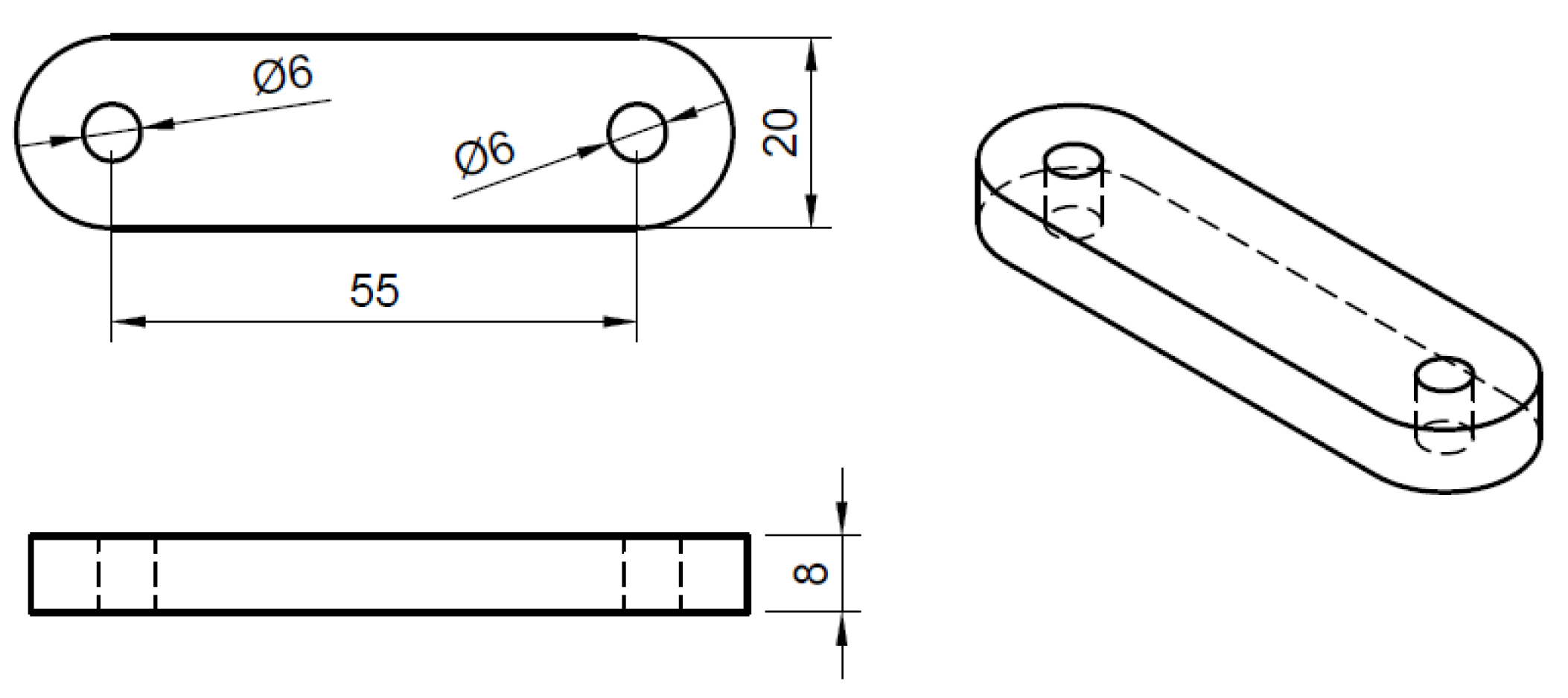
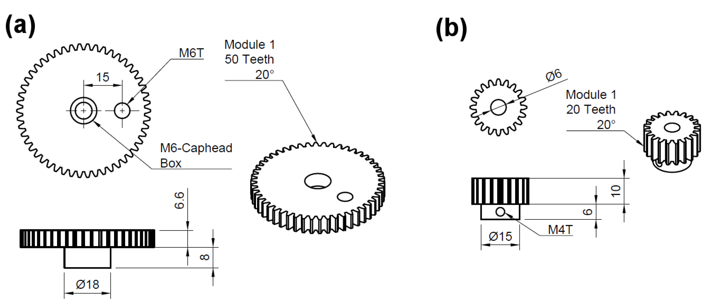
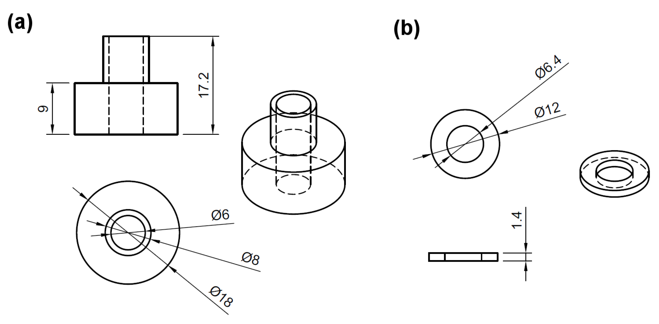
5.2. CLAPER Prototype

Here we include the schematics of the most important mechanical parts of the design:
The system was driven by a DC motor ∼60 RPM in the absence of load with a maximum torque of 180 N cm. which was coupled directly to the small gear. The mechanical assemble can be seen in Figure 1 and a schematic showing the details of the assemble process in shown in Figure 14. For motion axes stainless-steel M6, cap-head screws were used with non-threaded sections. They were fixed on the M6T threads made on the base-plate, gears, or long bars with an additional counter-nut on the opposite side. All parts were machined in aluminum, except for the bush-bearings and washers (Figure 13), which were made from brass, the 50-teeth gears, which were made from brass commercial gears and the 20-teeth gear which was made from a commercial stainless-steel gear. Nylon screws were used at the M6T threads on the long arm 110 mm from the pivot point in order to give support and fine alignment control, also a counter-nut was used to fix the adjustment. A commercial PEEP-valve was fitted to the exhaust of the bag-valve in order to have control on the end-exhalation-pressure.

5.3. eARM Prototype

Schematics of Prototype 2 (eARM) which is shown in Figure 15.
Design considerations:
  • A flexible and strong string is required (e.g., braided nylon cord), which should be able to carry enough weight, depending on the pressure which is to be achieved.
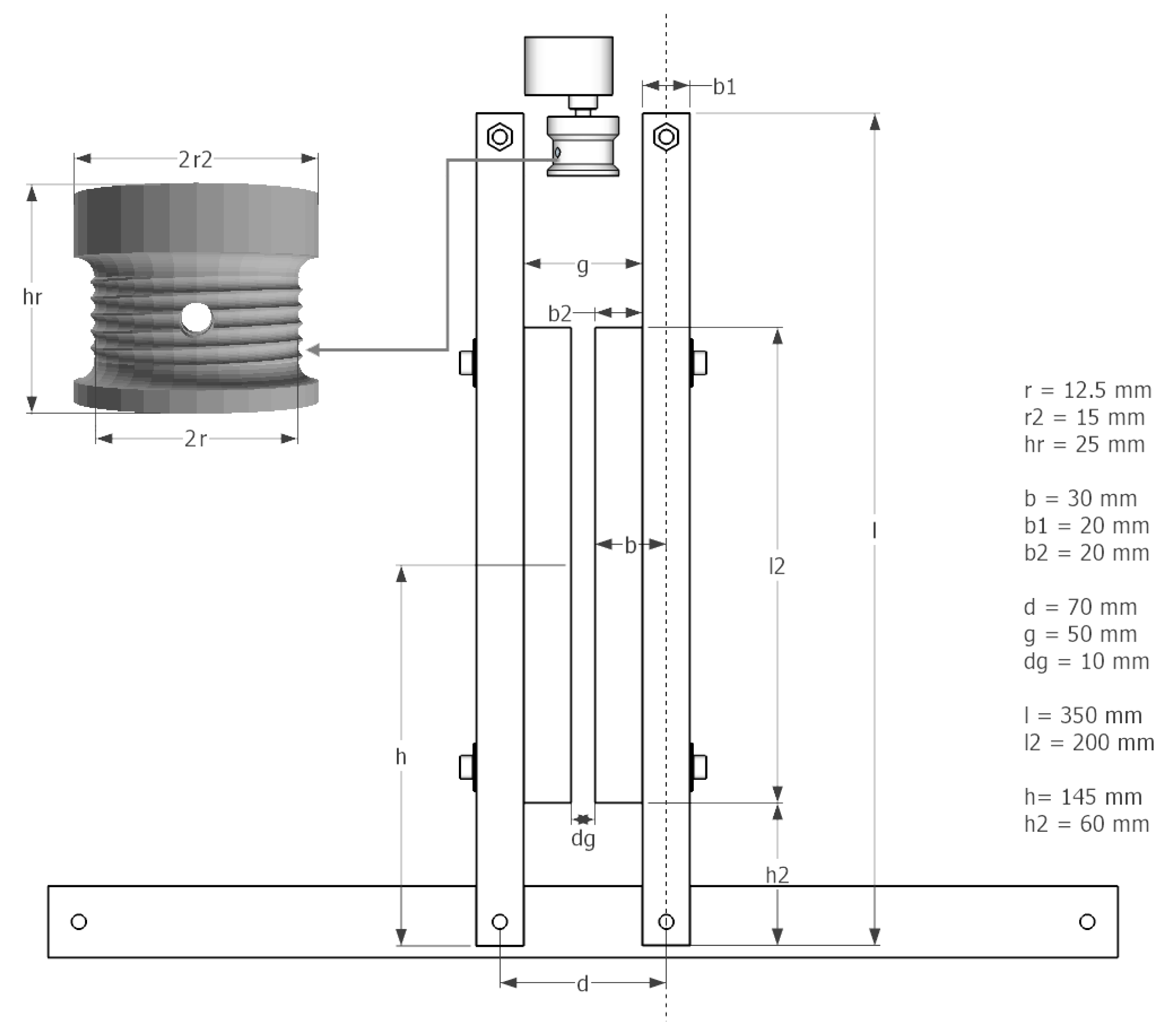
  • A spiral form in the string roll (see Figure 16) reduces jitter from string rolling up badly. Choosing a sufficient r2, in a way that squeezing is achieved in only a few turns, also helps avoiding jitter.
  • The string roll should enable easy installation/attachment of the string (e.g., twice through a hole in the string role).
  • An attachment on the arms (b2) helps pressing the bag-valve resuscitator while leaving space for the string roll (g > 2r2).
  • To avoid potential damages of the bag-valve resuscitator at the maximum squeezing, an additional space between the arms (dg) should be left.
  • Movable microswitches make setting up the device easier. The tunable position of the upper microswitch is essential for a manual volume and pressure control.
  • Two microswitches are needed to monitor and set respiration rate and inspiration to expiration ratio. Also if 1:1 ratio is the goal, keep in mind that opening and closing times differ.
  • Since bag-valve resuscitators are not designed for continuous long-term use, their characteristics and material can deteriorate with time. Regular rechecking and, if necessary, replacement are advised. Therefore, a design enabling relatively easy and quick replacement of it should be realized.
  • In Figure 17, the arm the length (l), spacing between the two rotational axis (d), bag-valve resuscitator position (h) and string roll radius (r) are shown. Accordingly a motor with appropriate characteristics (torque, rpm) have to be chosen in a way, that the squeezing process runs smoothly with the desired pace while reaching the desired pressure and volume.
  • By increasing l, the motor’s leverage also increases, if h stays unchanged. This means that a motor with less torque could perform the squeezing. However, in this case the end points of the arms have to travel a greater distance from released to squeezed state, meaning that the motor has to rotate faster at the same r2 of the string role to maintain the same rate of squeezing (BPM). By increasing the r2, the speed of the motor could be kept unchanged, however, this would cancel out the leverage gained by increasing l. Nevertheless, these relations allow for some tunability of the design according to the needs.
  • The systems requires active control from a microcontroller and we propose the connection schematics shown in Figure 18. The microcontroller used was the ArduinoUNO platform and the code can be found in the supplementary information.

Author Contributions

Conceptualization, E.C.-C. and M.K.; data curation, E.C.-C., J.O., G.H.-C., B.S. and J.T.; formal analysis, E.C.-C., J.O., C.M., G.H.-C., B.S., J.T. and J.W.; funding acquisition, E.C.-C. and M.K.; investigation, E.C.-C., J.O., C.M., G.H.-C., B.S., J.T., K.K., C.S., F.H., G.K., P.M. and J.N.; methodology, E.C.-C., J.O., C.M., G.H.-C., B.S., J.T., A.R.-M., J.W., T.W. and B.B.; project administration, M.K.; resources, E.C.-C. and M.K.; software, J.O., J.T., S.K., C.S. and D.G.; supervision, J.O. and M.K.; validation, E.C.-C., J.O., C.M., G.H.-C., B.S., J.T. and J.W.; visualization, E.C.-C., J.O. and C.M.; writing—original draft, E.C.-C., J.O., C.M. and J.N.; writing—review and editing, E.C.-C., J.O., C.M., G.H.-C., B.S., J.T., A.R.-M., K.K., S.K., C.S., J.W., F.H., G.K., P.M., J.N., T.W., B.B. and M.K. All authors have read and agreed to the published version of the manuscript.

Funding

We acknowledge financial support from the Minister for Higher Education, Research and the Arts of the German State of Hessen and from the Sparkasse Marburg-Biedenkopf. ECC wants to thank financial support through an Experienced Research Fellowship from the Alexander von Humboldt Foundation.

Conflicts of Interest

The authors declare no conflict of interest.

References

  1. Ranney, M.L.; Griffeth, V.; Jha, A.K. Critical Supply Shortages—The Need for Ventilators and Personal Protective Equipment during the Covid-19 Pandemic. N. Engl. J. Med. 2020, 382, e41. [Google Scholar] [CrossRef] [PubMed]
  2. Young, J.; Sykes, M. Assisted ventilation. 1. Artificial ventilation: History, equipment and techniques. Thorax 1990, 45, 753. [Google Scholar] [CrossRef] [PubMed] [Green Version]
  3. Powelson, S.K. Design and Prototyping of a Low-Cost Portable Mechanical Ventilator. Ph.D. Thesis, Massachusetts Institute of Technology, Cambridge, MA, USA, 2010. [Google Scholar]
  4. Malya, R.; De Santiago, C.; Dickman, N.; Nasteff, M.; Nonet, T.; Sundaramraj, A.; Vasquez, K.; Abidi, S.; Oden, M. A Novel Augmentation Device for Ventilation Utilizing the Bag Valve Mask in EMS and Resource Limited Settings. Circulation 2019, 140, A14208. [Google Scholar]
  5. Vicente, V.C.; Padilla, J.N.; Tanguilig III, B.T. Portable automated bag-valve mask with android technology. Int. J. Adv. Technol. Eng. Explor. 2016, 3, 28. [Google Scholar] [CrossRef]
  6. MIT Emergency Ventilator (E-Vent). Available online: https://e-vent.mit.edu/ (accessed on 12 August 2020).
  7. Kwon, A.H.; Slocum, A.H.; Varelmann, D.; Nabzdyk, C.G. Rapidly scalable mechanical ventilator for the COVID-19 pandemic. Intensive Care Med. 2020, 46, 1642–1644. [Google Scholar] [CrossRef] [PubMed]
  8. PROJEKT DIY-BEATMUNGSGERÄT. Available online: http://diy-beatmungsgerat.de/ (accessed on 27 September 2020).
  9. Emergency Ventilator Response: Spiro Wave. 2020. Available online: https://ventilatorresponse.com/ (accessed on 27 September 2020).
  10. Buytaert, J.; Abud, A.A.; Akiba, K.; Bay, A.; Bertella, C.; Bowcock, T.; Byczynski, W.; Coco, V.; Collins, P.; Francisco, O.; et al. The HEV Ventilator Proposal ventilator proposal. arXiv 2020, arXiv:2004.00534. [Google Scholar]
  11. Williams, L.M.; Sharma, S. Ventilator Safety. In StatPearls [Internet]; StatPearls Publishing: Tampa/St. Petersburg, FL, USA, 2019. [Google Scholar]
  12. Bezzant, T.B.; Mortensen, J. Risks and hazards of mechanical ventilation: A collective review of published literature. Disease-a-Month 1994, 40, 585–638. [Google Scholar] [CrossRef]
  13. Ates, A.; Arikan, M.; Ozgok, A. Use of Bag Valve Device Resulting in Pneumothorax. J. Case Rep. 2017, 6, 595–597. [Google Scholar] [CrossRef] [Green Version]
  14. Whipp, B. Pulmonary ventilation. In Comprehensive Human Physiology; Springer: Berlin, Germany, 1996; pp. 2015–2036. [Google Scholar]
  15. Overview of Initiating Invasive Mechanical Ventilation in Adults in the Intensive Care Unit. Available online: https://www.uptodate.com/contents/overview-of-initiating-invasive-mechanical-ventilation-in-adults-in-the-intensive-care-unit (accessed on 5 April 2020).
  16. Health and Human Services Department. Declaration Under the Public Readiness and Emergency Preparedness Act for Medical Countermeasures Against COVID-19, 17 March 2020. Fed. Regist. 2020, 85, 15198. [Google Scholar]
  17. Evita V800/V600 Intensive Care Ventilator: Instructions for Use. Available online: www.draeger.com/Products/Content/evita-v800-v600-sw-1n-ifu-9055601-en.pdf (accessed on 28 September 2020).
Figure 1. Three-dimensional render of the prototype of the contingence life-support air pressure emergency respirator (CLAPER).
Applsci 10 07229 g001
Figure 2. (a) Pressure as a function of time for pivot positions 1 (lighter color) to 5 (darker color). (b) Peak pressure from plots in (a) as a function of pivot position. (c) Flow generated as a function of time for pivot positions 1 (lighter color) to 5 (darker color). (d) Peak inspiratory (circles) and expiratory flow (squares) as a function of pivot position. (e) Volume pumped as a function of time for pivot positions 1 (lighter color) to 5 (darker color). (f) Peak volume pumped for the various pivot positions, the gray boxes show the recommended tidal volumes (6 to 8 mL/kg) for various predicted body weights (ideal weights) calculated from the parameters in Table 1.
Applsci 10 07229 g002
Figure 3. Three-dimensional render of the experimental actuated resuscitator machine (eARM) prototype.
Applsci 10 07229 g003
Figure 4. eARM measurement results. (a) Pressure as a function of time for microswitch positions 1 (lighter color) to 5 (darker color). (b) Peak pressure from plots in (a) as a function of microswitch position. (c) Flow generated as a function of time for microswitch positions 1 (lighter color) to 5 (darker color). (d) Peak inspiratory (circles) and expiratory flow (squares) as a function of microswitch position. (e) Volume pumped as a function of time for microswitch positions 1 (lighter color) to 5 (darker color). (f) Peak volume pumped for the various microswitch positions, the gray boxes show the recommended tidal volumes (6 to 8 mL/kg) for various predicted body weights (ideal weights).
Applsci 10 07229 g004
Figure 5. Measurements performed in order to demonstrate the additional features that can be implemented relatively easily with a digital control and a pressure sensor. Respiration rate was set to 15 BPM with inspiration to expiration ratio set to 1:2. The system was also set to trigger a breathing cycle in case of a potential inspiration (marked in gray) and to maintain positive end-expiratory pressure (PEEP), which was done with an additional mechanical PEEP valve and pressure dependent motor control. (a) Pressure obtained along several respiratory cycles. An inspiration was triggered when the pressure dropped by 2 cm H 2 O (red circles) with respect to PEEP. This pressure drop is the signal that corresponds to a patient attempting to breath in. PEEP was set to 7 cm H 2 O (dashed line). (b) Flow as a function of time. (c) Volume pumped as a function of time.
Applsci 10 07229 g005
Figure 6. Photograph of the CLAPER (a) and eARM (b) prototypes constructed.
Applsci 10 07229 g006
Figure 7. Schematic representation of the baseplate. Sizes shown are just for reference and have not been optimized. The design will require adjustments.
Applsci 10 07229 g007
Figure 8. Schematic representation of the connecting rod. Sizes shown are just for reference and have not been optimized. The design will require adjustments.
Applsci 10 07229 g008
Figure 9. Schematic representation of the arm rod. Sizes shown are just for reference and have not been optimized. The design will require adjustments.
Applsci 10 07229 g009
Figure 10. Schematic representation of the bag-pusher. Sizes shown are just for reference and have not been optimized. The design will require adjustments.
Applsci 10 07229 g010
Figure 11. Schematic representation of the M1 50 theeth (a) and M1 20 theeth (b) gears used. Sizes shown are just for reference and have not been optimized. The design will require adjustments.
Applsci 10 07229 g011
Figure 12. Schematic representation of the Teflon-bearing used under the 50-teeth gears. Sizes shown are just for reference and have not been optimized. The design will require adjustments.
Applsci 10 07229 g012
Figure 13. Schematic representation of the bush-bearing used at the long arm pivot position (a) is the main body of the bearing, (b) is a washer that maintains the bar in place. Sizes shown are just for reference and have not been optimized. The design will require adjustments.
Applsci 10 07229 g013
Figure 14. Schematic representation of the assemble. The design will require adjustments.
Applsci 10 07229 g014
Figure 15. Three-dimensional render of the eARM prototype diagonally and from the front. Yellow: Motor with string roll, Orange: Squeezing arms, Green: Upper endswitch (volume and pressure control), Red: Lower endswitch (Timing control). The design will require adjustments.
Applsci 10 07229 g015
Figure 16. Schematic of the eARM system with arms in the maximum compression position. The design will require adjustments.
Applsci 10 07229 g016
Figure 17. Schematic of the eARM system with minimum compresion showing the bag-valve resuscitator. The design will require adjustments.
Applsci 10 07229 g017
Figure 18. Schematic of the electrical connections for eARM system. The design will require adjustments.
Applsci 10 07229 g018
Table 1. Setting parameters for a mechanical ventilator [15]. * Breaths per minute. ** Acute respiratory distress syndrome.
ParameterValue
Tidal volume6–8 mL/kg PBW
Rate2–16 BPM *, for ARDS ** up to 35 BPM *
PEEP5–10 cmH 2 O
FiO2Adjusted to obtain SpO2 > 90%
Inspiratory flow40–60 L/min
Insp:exp ratio1:1–1:3
PSV5–10 cmH 2 O
Insp. pressure12–25 cmH 2 O (typ.)
Trigger pressure−2 to −1 cmH 2 O
Trigger flow2 L/min
Table 2. Comparison of main characteristics of a state-of-the-art mechanical ventilator (Dräger Evita) [17], the CLAPER and the eARM systems. a Externally controllable by voltage supply, b digital control tested in the range of 4–8. c Externally operated.
ParameterTypical (ARDS)EvitaCLAPEReARM
Tidal volume (mL)100–8002–3000227, 338, 460, 595, 7220–800
Rate (BPM)2–350.5–9815–24 a 8–30
PEEP (cm H 2 O)5–100–500–400–40 b
FiO2 (%)0–9021–100E/O c E/O c
Inspiratory flow (L/min)40–602–12030–5621–49
Insp:exp ratio1:1–1:3600:1–1:3001:11:1, 1:2
PSV (cm H 2 O)5–100–950–510–44
Insp. pressure (cm H 2 O)12–250–9510–4510–100
Trigger pressure (cm H 2 O)−2–−1N/AN/A−2–0
Trigger flow (L/min)20.2–15N/AN/A
Publisher’s Note: MDPI stays neutral with regard to jurisdictional claims in published maps and institutional affiliations.

