Article

A Simplified CityGML-Based 3D Indoor Space Model for Indoor Applications

1
School of Geosciences and Info-Physics, Central South University, Changsha 410083, China
2
School of Hydraulic and Ecological Engineering, Nanchang Institute of Technology, Nanchang 330099, China
*
Authors to whom correspondence should be addressed.
Appl. Sci. 2020, 10(20), 7218; https://doi.org/10.3390/app10207218
Submission received: 20 September 2020 / Revised: 11 October 2020 / Accepted: 13 October 2020 / Published: 16 October 2020
(This article belongs to the Special Issue BIM and GIS Integration for Driving Smarter Decisions)

Abstract

:
With the continuous development of indoor positioning technology, various indoor applications, such as indoor navigation and emergency rescue, have gradually received widespread attention. Indoor navigation and emergency rescue require access to a variety of indoor space information, such as accurate geometric information, rich semantic information and indoor spatial adjacency information; hence, a suitable 3D indoor model is needed. However, the available models, such as BIM and CityGML, mainly represent geometric and semantic information of indoor spaces, and rarely describe the topological adjacency relationship of interior spaces. To address the requirements of indoor navigation and emergency rescue, a simplified 3D indoor model is proposed in this research. The building components and indoor functional spaces of buildings are described in a simplified way. The geometric and semantic information are described based on CityGML, and the topological relationships of indoor adjacent spaces are represented by CityGML XLinks. While describing the indoor level of detail (LOD) of buildings in detail, the model simplifies building components and indoor spaces, which can preserve the characteristics of indoor spaces to the maximum extent and serve as a basis for indoor applications.

1. Introduction

Smart cities, as a new urban development concept, extend people’s perceptions and explorations of spatial information from outdoor spaces to indoor spaces [1,2]. In particular the continuous development of indoor positioning technology has given rise to many indoor space applications, such as indoor navigation, indoor emergency rescue, and indoor path planning [3,4,5,6]. With the help of various indoor positioning technologies [7,8,9,10,11,12], people can easily get from one place to another in an indoor environment. In the event of an indoor emergency, such as a fire, rescuers are able to quickly develop evacuation routes to protect life and property to the greatest extent possible. However, the increasing complexity of high-rise buildings has also led to an increasingly complex indoor space environment. The complexity of indoor spaces is partly a barrier to efficient indoor navigation and rapid emergency response but also highlights the importance of indoor navigation and emergency rescue. Unlike outdoor spaces, people are exposed to various obstacles, such as walls and indoor facilities, when passing through indoor spaces. Therefore, indoor navigation requires detailed information about indoor spaces, such as the location of indoor spaces and the spaces adjacent to an indoor space. In this context, a three-dimensional model that can accurately describe the complex environment of an indoor space in detail is indispensable [13].
A 3D model that describes the geometric, semantic, and even topological information of a building’s indoor space plays an important role in indoor spatial inquiry, spatial analysis, and the generation of path information. In terms of 3D models for buildings, the well-known Building Information Modeling (BIM) [14] can describe the geometric and semantic information of buildings in detail. As the primary data exchange standard of BIM, the Industry Foundation Classes (IFC) standard developed by buildingSMART [15] describes geometric and semantic information of building components for indoor spaces with a variety of classes, such as IfcWall, IfcSlab, and IfcSpace, which can serve as the basis for indoor applications, such as indoor navigation and emergency rescue [4,16]. However, the building elements in IFC are mostly described by Swept Solid and Constructive Solid Geometry (CSG), while only a small portion of the elements are described by Boundary Representation (Brep), which is widely used in the GIS domain [17,18]. On the other hand, although BIM models provide rich information about buildings, they do not have the spatial analysis capabilities [19,20]. Therefore, in most cases, BIM models are used as an ideal source of 3D data for conversion to GIS data, such as converting BIM data in IFC to 3D GIS data in CityGML [17].
City Geography Markup Language (CityGML) [21] from the Open Geospatial Consortium (OGC) is an open data model used for the representation and exchange of 3D city models. In the current version, 2.0 [22], CityGML adopts five different levels of detail (from coarse LOD0 to highly detailed LOD4) to represent various features in city models, ranging from a single building to a whole city. Thanks to the concept of LODs, CityGML has a wide range of applications, such as indoor navigation and emergency rescue [23,24]. The building model of CityGML is able to represent the thematic and spatial aspects of buildings in LOD0 to LOD4. In LOD4, geometric and semantic information about the interior spaces of a building are described in detail. Geometrically, Brep is used to represent the geometry of building components. For example, floors, ceilings and interior walls are represented by surfaces and a room is represented by a solid, which semantically correspond to FloorSurface, CeilingSurface, InteriorWallSurface and Room, respectively. Topologically, CityGML adopts the XML concept of XLinks to represent a common geometrical object shared by two solids. The XLink topology is nearly as powerful as the explicit GML3 topology but simpler and more flexible.
However, the LODs concept in the current version is no longer sufficient to meet the requirements of emerging indoor applications, such as indoor navigation [25]. On the one hand, it is necessary to acquire the rooms adjacent to a certain room for indoor navigation. However, the descriptions for indoor spaces in LOD4 do not reflect two adjacent rooms sharing the same interior wall. On the other hand, LOD4 adds detailed indoor space information to LOD3, where the exterior shape of a building is the most detailed, which means that all the details of a building are described in LOD4. Indoor navigation requires access to detailed interior building information but not detailed exterior information. A revised LODs concept will be included in the forthcoming version: CityGML 3.0 [26]. The new definition of LODs is flexible to represent a detailed indoor model with a coarse exterior building shape, which may be beneficial to indoor applications, such as indoor navigation.
Unlike several 3D modelling standards such as IFC and CityGML, which cover geometrics and semantics of interior spaces, IndoorGML [27] dedicates to model interior spaces for the purpose of indoor navigation. As an OGC standard, IndoorGML allows to represent and exchange indoor spatial information to construct indoor navigation systems. It provides a core data model to represent topological connectivity of indoor space and a network model in indoor space for indoor navigation. However, to avoid reduplicative efforts with IFC and CityGML, IndoorGML includes merely geometrics and semantics of building components, which could serve as a complementary model to IFC and CityGML for indoor navigation. Moreover, IndoorGML still has not yet represented the adjacency of interior spaces, such as two adjoining rooms sharing a wall, even though it describes the topological connectivity.
With respect to 3D models for cadastral systems, the Land Administration Domain Model (LADM) [28] provides an abstract and conceptual model which describes basic administrative objects for land administration. The administrative units in LADM are described as legal spaces which can be connected with physical features in other models, such as the combination of LADM and CityGML to develop 3D cadastral systems [29,30,31] and the integration of LADM and IndoorGML to support indoor navigation [32] and emergency evacuation [33]. Since 3D cadastral objects are described as closed volumetric ones bounded by property boundaries, a large amount of literature focuses on the valid representation of 3D parcel of cadastral models and the automatic construction of 3D volumetric object [34,35,36]. However, 3D cadastral models rarely address the more detailed building components, such as doors and windows, or the topological adjacency relationship between rooms. Therefore, 3D cadastral models are not entirely suitable for describing 3D interior spaces.
In this research, we introduce the simplified 3D indoor space model based on CityGML. The model describes accurate geometric information of building indoor spaces with rich semantic and corresponding topological information. The model is designed according to CityGML3.0′s LODs concept, taking into account the requirements of indoor navigation and emergency rescue, highlighting the detailed description for indoor space information while ignoring exterior description of buildings. The geometric representation and semantic types of the model still follow the CityGML2.0 schema, and the topological relationship is described for adjacent rooms by XLinks.
The remainder of this paper is organized as follows. In Section 2, we discuss the current CityGML LODs concept and simplified representation for buildings. The detailed design and representation of the simplified 3D indoor space model is proposed in Section 3. In Section 4, the CityGML dataset is extracted from BIM data using FME based on the model. Some conclusions and future work are given in Section 5.

2. Background and Related Work

The building module of CityGML 2.0 gives different detailed descriptions of the same building using LOD0 to LOD4, as shown in Figure 1. A building is represented as a footprint by a horizontal 3D surface in LOD0. LOD1 is represented as coarse a block-shaped model by a solid or multisurface. LOD2 adds simplified roof structures to LOD1, and the outer surfaces of a building can be represented semantically by thematic features. Openings (windows, doors) and other detailed exterior structures are added to LOD2 to obtain the most accurate exterior representation: LOD3. In LOD4, detailed interior building structures, which are composed of rooms probably with furniture, can be modeled upon LOD3.
The LODs concept of CityGML2.0 allows descriptions for the same features at different levels of detail. This allows handling of the complexities of urban models and facilitates spatial analysis and visualization [25]. However, the concept also creates some problems. For example, the interior spatial structure of a building can only be described in LOD4, which means that the detailed indoor information can only be described based on LOD3, which is the most detailed exterior shape of a building. This definition somewhat hinders indoor applications, such as indoor navigation, which require access to detailed indoor space information but not precise exterior building information.
There have been a number of efforts to refine the LODs concept of CityGML2.0. Typical improvements include the progressive definitions of LODs for geometric and semantic levels of detail [38,39], the progressively finer levels of detail descriptions for indoor and outdoor spaces [40,41], and mapping the LOD4 descriptions of the current version for indoor spaces to four levels of detail, LOD0 to LOD3, to describe indoor space information [25,38]. Consequently, in the upcoming version, CityGML 3.0, LOD4 will be removed, and all objects (including the interior of a building) can be represented in LOD0 to LOD3. For example, it is possible to represent the interior structure of a building in LOD3 with a coarse exterior shell in LOD1. The new LODs concept greatly increases the flexibility of interior space descriptions. Therefore, LODs can be tailored according to different indoor applications without having to limit the interior space information to only one level of detail.
While there is a large amount of literature that focuses on improving the geometric and semantic LODs of the current version, limited literature has reported on the topological description of CityGML for interior spaces. In CityGML2.0, a geometric object shared by other geometric objects can be referenced by a GML geometry attribute xlink: href. Figure 2 shows that two solids (s1 and s2) share a common surface (surface1, blue). Hence, the geometry of surface1 is represented only once and referenced by the two solids through XLinks. The topology representation of XLinks is limited to the features that have a shared geometry object. However, the XLink topology is not used to describe interior spaces that share a common building element in CityGML.
In Figure 3, although room1 is adjacent to room2 and wall w1 is the common element, CityGML uses the two sides of the wall (thick wall) to represent the boundary surfaces of the two rooms, respectively, yielding two separate indoor spaces without using XLinks to describe the shared common element: The interior wall. Not only does this description for rooms have some data redundancy, but it does not represent the topological relationship of the rooms. Likewise, the topological relationship of the adjacent rooms upstairs and downstairs is also not represented. Moreover, the topological relationship description is not specified in the schema and Unified Modeling Language (UML) document of CityGML 3.0 [42,43], which is under development.
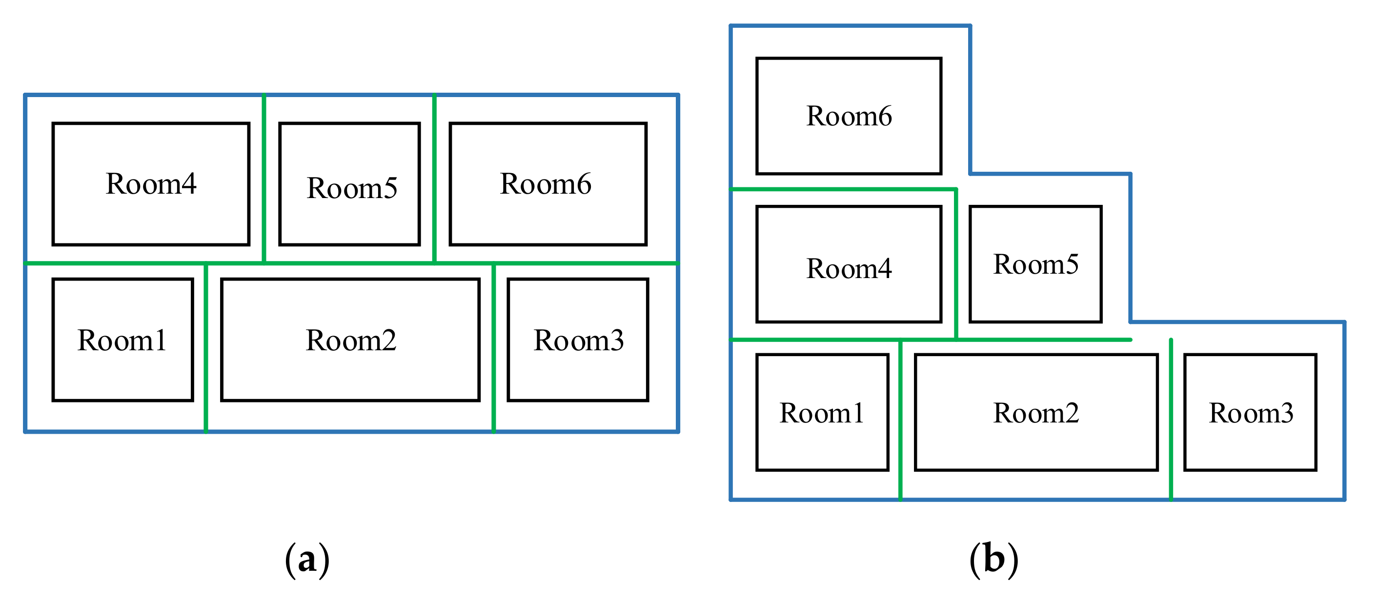
Topology relationships of indoor spaces are the basis for indoor spatial queries, and the establishment of explicit topology relationships can be helpful in constructing adjacencies of indoor spaces and generating indoor paths [44]. One approach that can be attempted to establish topological relationships for indoor spaces is to simplify building components, such as walls, by reducing the thickness to a thin surface [45] and representing two adjacent rooms that share the common surface. The simplified description of a building in the literature [45] can be summarized as follows: In the simplified model, the exterior boundary surface of a building is the outer contour of the building, while the interior boundary surface is located at the center of the interior wall, as shown in Figure 4a. However, this approach cannot be applied to buildings with irregular outer contours. In Figure 4b, for example, if the exterior boundary surface is still the outer contour of the building, the rooms will be unenclosed and the topological relationships of the rooms could not be represented. Furthermore, the method does not attempt to simplify the building components between stories.
Joon-Seok Kima et al. [46] proposed a geometrically simplified description for the interior spaces of buildings using the prism model. However, the prism model is not applicable to the top and bottom faces of an indoor space with different 2D footprints. In addition, this method does not involve the simplification of doors and windows. Some methods [47,48] that simplify the CityGML high-level LOD models to generate low-level LOD models only simplify the exterior characteristics of buildings and cannot be used to describe the simplification of interior structures.
In summary, the existing literature indicates that the LODs concept in the current version, CityGML 2.0, is no longer sufficient for emerging indoor applications. Indoor 3D models suitable for indoor navigation and emergency rescue should be designed according to the requirements of indoor applications. On the one hand, the models are required to describe detailed indoor geometric and semantic information, but not all of the indoor details. On the other hand, considering the possible adjacency among indoor rooms, the topological relationships of rooms should be described according to the CityGML2.0 XLinks. However, there is, to the best of our knowledge, no 3D indoor model that can properly describe the geometric and semantic information of indoor spaces as well as the topological relationships of indoor spaces. Therefore, we introduce a simplified 3D indoor space model based on CityGML to aid in indoor navigation and emergency rescue. It should be noted that this research does not change CityGML descriptions for indoor spaces but attempts to suggest a 3D indoor model based on CityGML that is suitable for indoor applications, such as indoor navigation. Since CityGML3.0 is still under revision, this work still adopts the CityGML2.0 schema and UML to describe indoor spaces according to the CityGML2.0 encoding standard, while the CityGML3.0′ LODs concept is adopted for indoor LOD design.

3. Simplified 3D Indoor Space Model (3DSISM) Based on CityGML

Indoor spatial information in 3D indoor models is determined by different indoor applications. Indoor navigation is concerned with indoor spaces (e.g., rooms and corridors) and constraints (e.g., walls and doors) represented by various indoor spatial elements [27] of appropriate semantic type and geometric representation to define various physical and virtual spaces [26]. In addition, indoor spatial information should not only reflect the indoor space environment of a building but also consider navigation constraints, such as adjacencies of indoor spaces and indoor paths [5,13]. Therefore, 3D indoor spatial information should contain detailed geometric and rich semantic information about various indoor functional spaces and building components, such as rooms, stairs, walls, ceilings, doors, and windows, which organize the indoor spaces into a number of spatial units and spatial relationships and provide appropriate information for indoor applications, such as indoor navigation. It is worth mentioning that there are a large number of facilities in indoor spaces, such as furniture. These furnishings occupy a certain amount of interior spaces and are obstacles to indoor navigation and emergency rescue, which should be avoided when developing indoor paths. Therefore, indoor spatial information should include the description of furniture. However, in this study, we put emphasis on the representation of building components and indoor functional spaces, while the description of furniture is beyond the scope of this research.

3.1. LOD of the 3DSISM

3.1.1. Geometry Model for Indoor Spaces

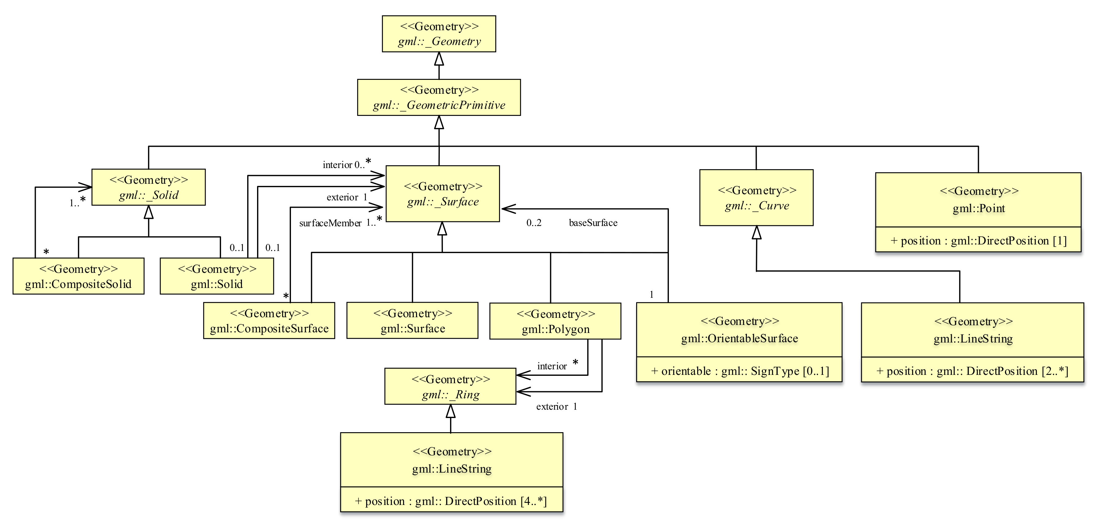
CityGML adopts the objects of GML3 [49] geometric model based on ISO19107 “spatial model” [50] to describe the geometric properties of city model features using Boundary Representation (Brep). To describe the geometric properties of 3D indoor spaces, a subset of the CityGML geometric model can be used, as shown in Figure 5. A zero-dimensional object is a point (Point), a one-dimensional object is a curve (_Curve), a two-dimensional object is a surface (_Surface), and a three-dimensional object is a solid (_Solid). A solid is bounded by surfaces and a surface is enclosed by curves. Curves are not allowed to cross and two curves intersect at a common point. A curve is defined as a straight line using GML3 class LineString. A surface is defined as a plane, represented by a polygon, which is topologically closed. The ring (_Ring) is the boundary of a polygon, and the geometry is a closed linear ring (LinearRing). A polygon consists of an outer ring and zero to multiple inner rings.

3.1.2. Definition of the LOD for Indoor Spaces

The LODs concept of CityGML 3.0 allow to describe a detailed indoor space structure with a coarse exterior building shape or even a user-defined geometric and semantic LOD [26,51]. Therefore, we try to describe the detailed indoor space while ignoring the exterior building information. The geometric model in Section 3.1.1 and the corresponding semantic classes are used to describe indoor spaces and building components in detail, while exterior building shape is not represented in the LOD defined in this research.
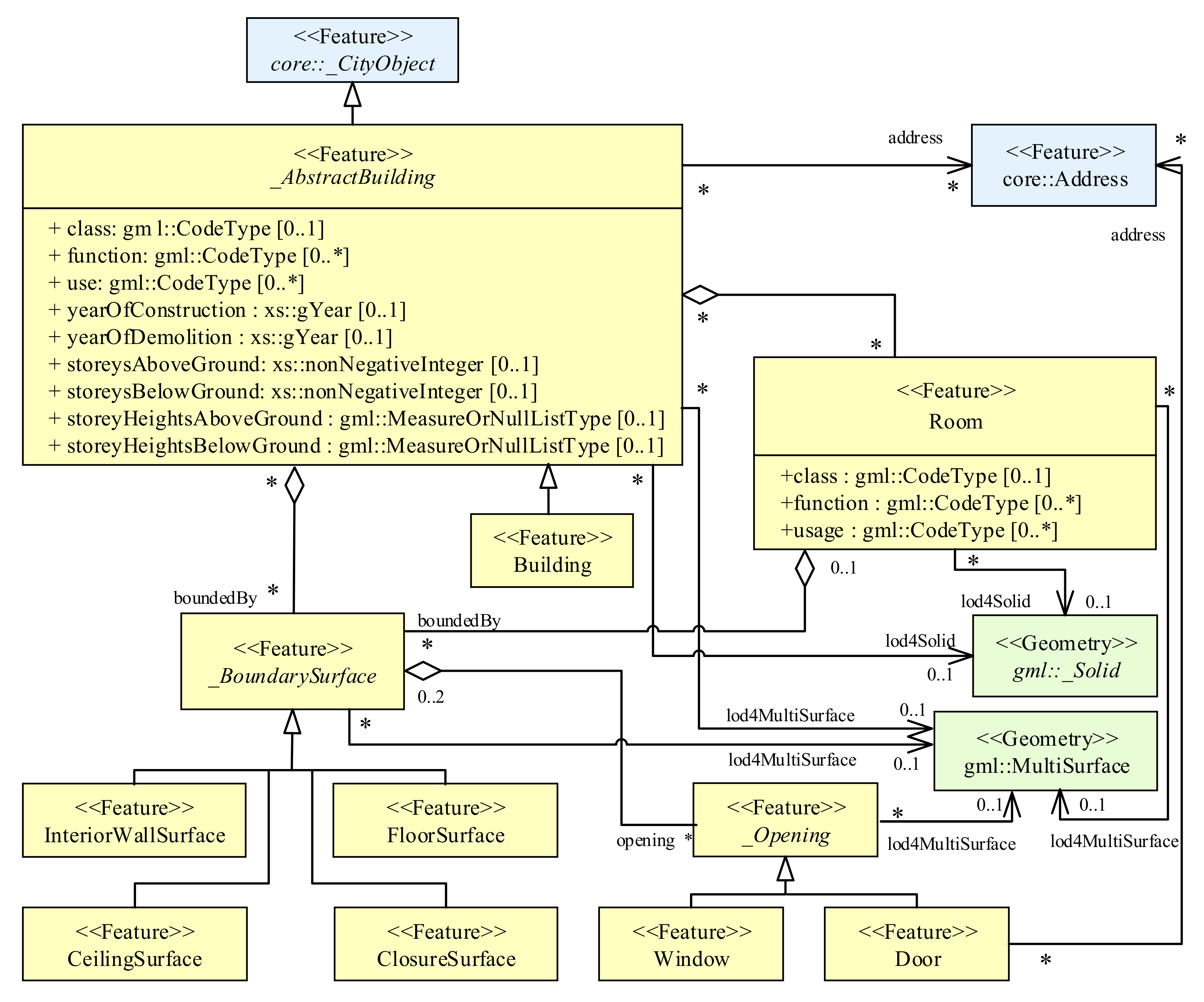
In this work, indoor building spaces are decomposed into subspaces, which can be semantically represented as rooms, corridors, stairs, elevators, etc., according to the function of indoor spaces. There are no gaps between subspaces nor can they penetrate each other. The UML diagram of the 3D indoor space model is shown in Figure 6.
Each subspace is represented by geometric primitive Solid, which is enclosed by its boundary surfaces. The semantic class _BoundarySurface defined by CityGML2.0 is adopted for boundary surfaces, such as InteriorWallSurface, FloorSurface and CeilingSurface. Since the 3D indoor model proposed in this paper describes only indoor space information, the semantic information that describes the building exterior, such as RoofSurface, WallSurface, and GroundSurface, has been removed from this model, and only the semantics that describe indoor spaces are retained.
For geometrically unenclosed spaces, a virtual surface, ClosureSurface [22], can be used to virtually enclose the spaces to form a closed solid. For example, an open balcony is not a closed space and ClosureSurface can be used to enclose it to construct a closed object. A corridor or hall is an open space that connects various rooms and stairs. Corridors and staircases are two different functional spaces and are usually connected without doors. Therefore, a ClosureSurface is employed as the common boundary surface to connect a corridor and stairs.
The adjacent spaces are connected through a common boundary surface using XLinks to describe the topological relationship of indoor spaces. As each 3D spatial entity in indoor spaces occupies its own independent space, these entities will not intersect each other. Hence, the topological relationships of indoor spaces are only the following: Contains, touch, and disjoint.

3.2. Simplified Representation for Indoor Spaces

CityGML2.0 LOD4 describes building information at the highest level of detail, including detailed exterior and interior building information. Although the 3D indoor space model proposed in this paper does not describe exterior information, not all indoor applications require the most detailed indoor information [39]. Therefore, the simplification of building components to generate lightweight but efficient indoor spatial data is an appropriate approach to model 3D indoor space for indoor navigation. The simplification of indoor spaces is largely different from that of the exterior shape of a building. The simplification of a building’s exterior is mostly a simplification of its exterior contours, removing unnecessary and redundant data to achieve a low level of detail to describe the building exterior. While the simplification of interior spaces requires a consideration of the geometric representation of building components, descriptions of the indoor spaces and relationships among indoor spaces according to the requirements of different interior applications. Therefore, principles of simplification are needed in the descriptions of interior spaces. It should be noted that we put emphasis on a simplified representation for building elements and indoor spaces, not a methodology for simplification.

3.2.1. Principles for the Simplified Representation

Indoor navigation requires not only geometric data with certain precision and clear semantic definitions but also topological relationships among indoor spaces. To meet the requirements of indoor navigation, this paper proposes the following principles for the simplified description of indoor spaces.
Principle 1: Appropriate accuracy. The indoor space environment of a high-rise building is exceptionally complex. The simplification of indoor spaces is a generalized and abstract expression of building components; thus, there is consequent loss in the geometric accuracy of indoor spaces. For indoor applications, such as indoor navigation, the locations in indoor spaces are required to be accessed; thus, simplification of indoor spaces should ensure the accuracy of indoor positioning. Currently, the accuracy of indoor positioning varies depending on the signal transmitted, principle of positioning and indoor environment. As an example, the low cost, high accuracy Ultrawideband (UWB) can achieve an average indoor positioning accuracy of 15 cm [52]. In addition, the CityGML LODs specify different accuracies for spatial features representation. In CityGML LOD4, the proposed absolute accuracy requirement for a 3D point should be 0.2 m or less. Therefore, the geometric simplification of building components should meet the corresponding accuracy requirements.
Principle 2: Reflection of the characteristics of indoor spaces. The geometric properties of building elements may change after geometric simplification, which may result in changes in the shape of indoor spaces. Simplification of indoor spaces should, therefore, reflect the geometric characteristics and layouts of indoor spaces, following the indoor LOD definition mentioned above.
Principle 3: Appropriate semantic description. Changes in the geometric properties of building components can result in inconsistencies in semantics after simplification. The semantic descriptions of building elements and indoor spaces should keep the original semantic properties, and if necessary, appropriate semantics should be reassigned according to the semantic classes of the LOD description in Section 3.1.2.
Principle 4: Topological consistency. The topological relationships of indoor spaces should be taken into account to avoid topological inconsistency, such as the topological relationship of adjacent rooms on the same story and/or upstairs and downstairs.
Principle 5: Applicability. Different buildings have different building components and spatial shapes. The simplified descriptions of building components should have a certain applicability, not just for a single building.

3.2.2. Simplified Representation for Building Components and Indoor Spaces

Different buildings have different indoor spaces and components types. In this work, the representative building components and indoor functional spaces are selected to be simplified and described according to the requirements of indoor navigation, following the principles of simplification.
  • Simplification and description of vertical building components
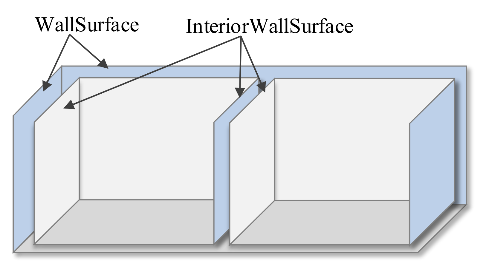
A wall separates outdoor and indoor spaces in the vertical direction, as well as different indoor rooms. In this work, the vertical components refer to walls. In CityGML, the walls separating outdoor and indoor spaces are described as walls and interior walls, respectively, while the walls separating different rooms are described as interior walls, as shown in Figure 7.
Considering the requirements of indoor navigation and the complexities of building outer contours (Figure 4b), in this work, all the walls (thick walls) of a building are represented as surfaces and are replaced by their center surfaces, according to the simplification principles, as shown in Figure 8. The simplified walls are geometrically represented by geometric primitive Polygon. Semantically, the walls separating outdoor and indoor spaces are simplified from exterior and interior walls to a single wall, resulting in semantic inconsistency. Since the indoor space model describes information about indoor spaces, the simplified wall is semantically described as InteriorWallSurface. In addition, the layouts of rooms in the same story are not exactly the same. After simplification, one side of a wall may be associated with two or more rooms, as shown in Figure 9. Considering the principle of topological consistency, the simplified wall should meet maximal segmentation so that there is only one room on each side of a wall. Two adjacent rooms share the wall, and XLinks is used to describe the topological relationships.
  • Simplification and description of horizontal building components
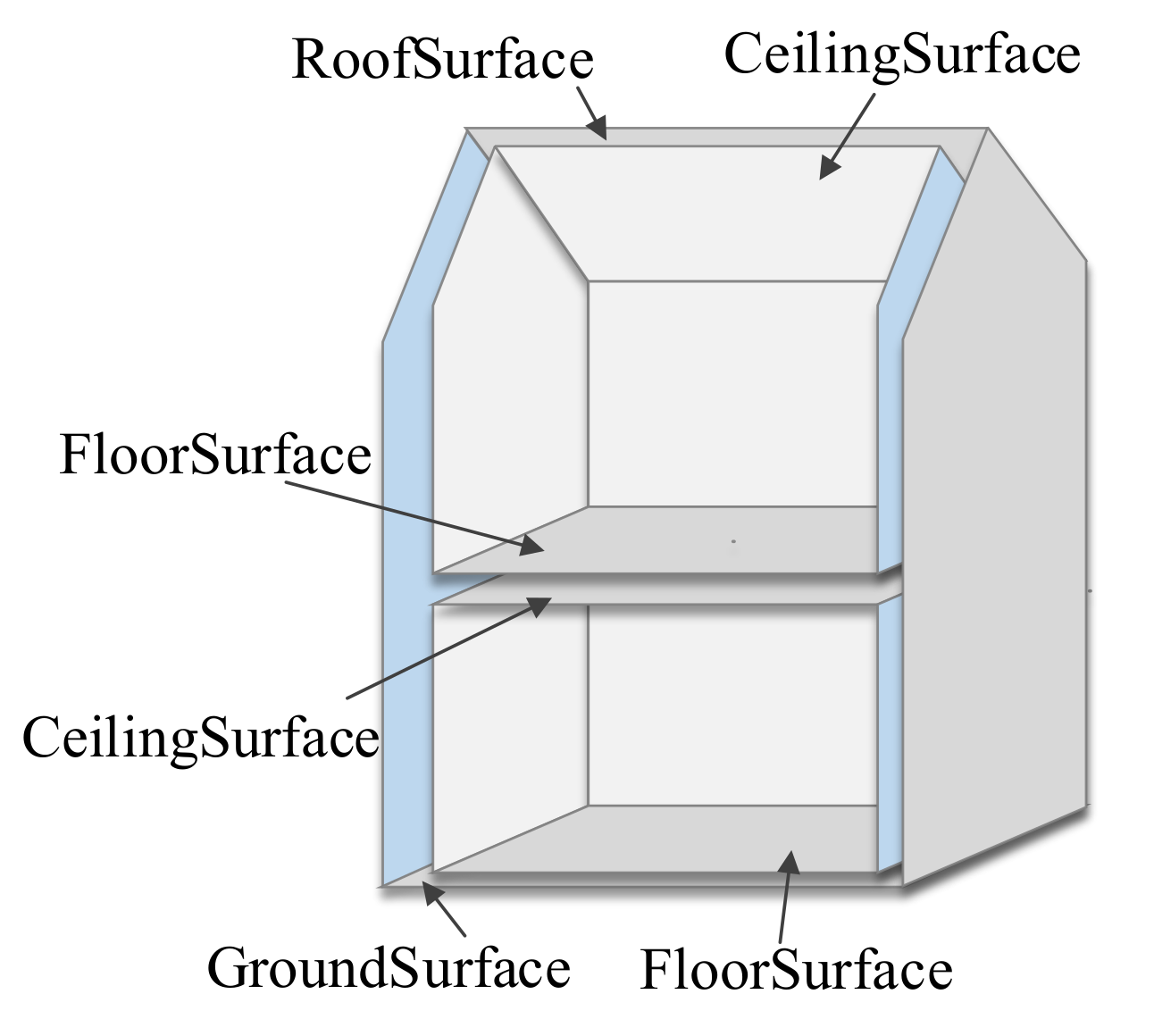
In CityGML, ceilings and floors separate different stories horizontally, roofs separate indoor spaces from outdoor space, and ground plates connect buildings with the ground, as shown in Figure 10. In this research, ceilings, floors, roofs, and ground plates are classified as horizontal building elements. Floors and ceilings separating adjacent stories, according to the principles above, are simplified and replaced by center surfaces and represented geometrically by geometric primitive Polygon. For two adjacent rooms upstairs and downstairs, the floor of one room is the ceiling of the other room after simplification, and both floor and ceiling are the same feature, resulting in a semantic inconsistency. Therefore, the simplified surface can be assigned either FloorSurface or CeilingSurface semantically but not both (as shown in Figure 11).
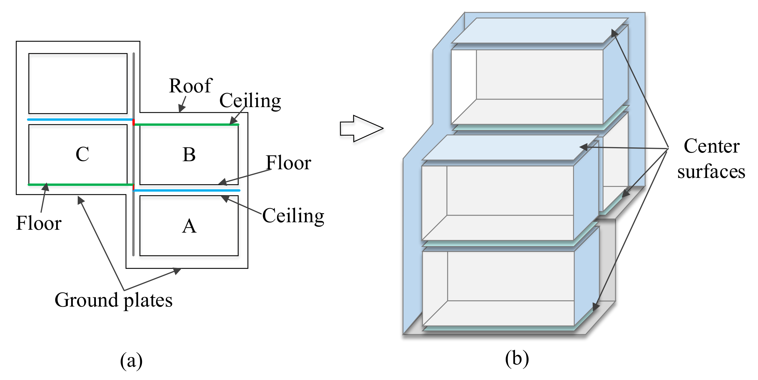
Indoor activities are in the story spaces between floors and ceilings, without being concerned with roofs and ground plates; however, when simplifying these building elements, irregular building shapes should be considered as much as possible. As shown in Figure 12a, the ground plates of the building are not on a horizontal plane. When the floor and ground plate of room C are simplified after simplifying the ceiling and floor between room A and room B with a center surface, there would be a geometric error if the ground plate was ignored and if only the floor of room C was retained. Therefore, floors and ground plates are also simplified with center surfaces. The simplified surface can be assigned FloorSurface semantically to describe semantic information of indoor spaces and to avoid semantic conflicts. The same is true for the simplification of ceilings and roofs, that is, center surfaces are used, and the simplified surfaces can be assigned CeilingSurface semantically.
The layouts of rooms on different stories are not vertically identical. After simplification, one side of the surfaces between adjacent rooms upstairs and downstairs may be associated with two or more rooms, as shown in Figure 13. Considering the principle of topological consistency, the simplification of horizontal building components should meet the maximal segmentation so that there is only one room on each side of a surface. XLinks is adopted to describe the topological relationships of adjacent rooms.
  • Descriptions of doors and windows
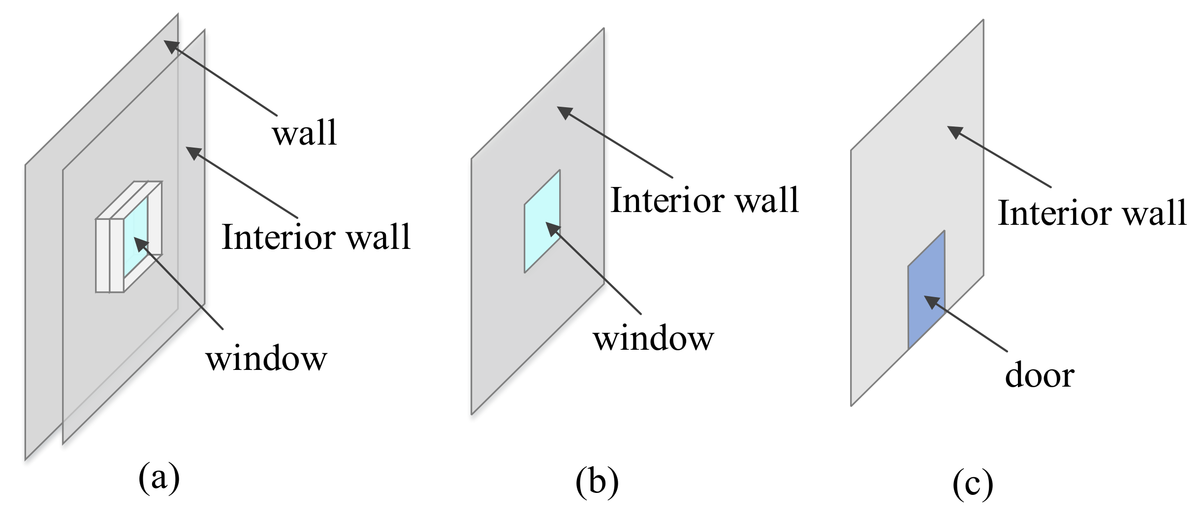
Doors and windows are building elements that connect functional spaces. In CityGML, doors and windows belong to the class Opening, with geometric properties represented by Polygon. Doors and/or windows are located in the center of an interior and exterior wall, or two interior walls, and are connected with walls to form a composited surface, as shown in Figure 14a. When a wall is simplified, a part of the walls is removed (the white part in Figure 14a), and a door and/or a window are connected to the simplified interior wall to form a composited surface. In general, a window is in an interior wall, and the boundary of the window is an inner ring of the interior wall; therefore, the window (Figure 14b) is a hole in the interior wall. A door (Figure 14c) is connected to an interior wall at common edges and is not a hole in the interior wall. Semantically, doors and windows maintain their original semantic properties and are objects of the class Opening.
  • Simplification and description of indoor functional spaces
1.
Description of Rooms and Corridors (or halls)
After the simplification of the building components above, it is possible to enclose indoor functional spaces, such as rooms and corridors, with the boundary surfaces. The indoor spaces are represented by Solid geometrically and as Room semantically with function, class and use [22] to specify a room or a corridor. A corridor is an open space that horizontally connects rooms and staircases. In general, a virtual surface, ClosureSurface, can be used as a common boundary surface between a corridor and a staircase to enclose spaces together with other boundary surfaces and to connect a corridor and a staircase.
2.
Simplification and description of stairs
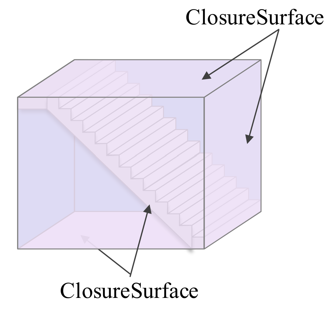
A stairs is a functional space connecting two adjacent stories. Stairs belong to the class IntBuildingInstallation in CityGML, of which the location and shape are represented in detail by GM_MultiSurface. However, indoor navigation and emergency rescue are not concerned with the detailed shape of a stairs but more with the indoor spaces connected to the stairs and the operation state of the stairs. Therefore, in this research, the shape, structure, and other details of a stairs are ignored, and it is described as a functional space enclosed by interior walls as well as virtual surfaces, and assigned Room as semantic property with function, class, and use, as shown in Figure 15.

4. Implementation

4.1. Experimental Data

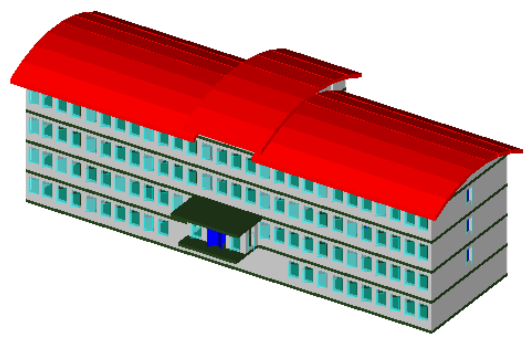
On the one hand, BIM model provides detailed geometric information and rich semantic information, and on the other hand, because of the lack of CityGML LOD4 data, in this work, the BIM data (in IFC4) [53] is taken as raw data, as shown in Figure 16. The building is composed of five stories named basement, ground level, 1 level, 2 level and roof level, where the roof level is not an indoor activity space; thus, will be removed in this work, and only the other four floors will be processed. Building components and indoor spaces are extracted according to the simplified description in Section 3 by Feature Manipulation Engine (FME, by Safe Software) to generate the CityGML dataset based on 3DSISM.

4.2. Data Extraction

According to the 3DSISM, data extraction consists of the following five steps: (1) Filtering and mapping of semantic types; (2) extraction and setting of attribute data; (3) transformation and setting of spatial reference system; (4) extraction of the building components; and (5) generation of indoor spaces.
  • Filtering and mapping of semantic types
The IFC defines numerous types of building components, with only a subset of the types associated with CityGML. An IFC file consists of a project (IfcProject) at the top. Under the project, there are one or more sites (IfcSite), which may include one or more buildings (IfcBuilding). A building may contain one or more stories (IfcBuildingStory), each of which contains various building elements, such as walls, slabs, and doors. According to the simplified 3D indoor model in Section 3, the IFC types shown in Table 1 are selected as the input data in this work, with the italicized descriptions in brackets referring to the data types provided to the corresponding CityGML dataset.
  • Extraction and setting of attribute data
The IfcProject describes the general properties of the project, such as GlobalId, Name, and Description, which can be renamed to CityModel of CityGML by AttributeManager transformer, such as GlobalId set to gml_id. Similarly, the IfcBuilding provides the attribute information of the building, which is converted to Building of CityGML by AttributeManager, as shown in Figure 17. It should be noted that CityModel is the top class of CityGML model, and Building is the child class of CityModel; hence, the ID: gml_id of CityModel is set as the parent ID: gml_parent_id of Building, and the ID: gml_id of Building is set as the parent ID: gml_parent_id of other building components.
  • Transformation and setting of spatial reference system
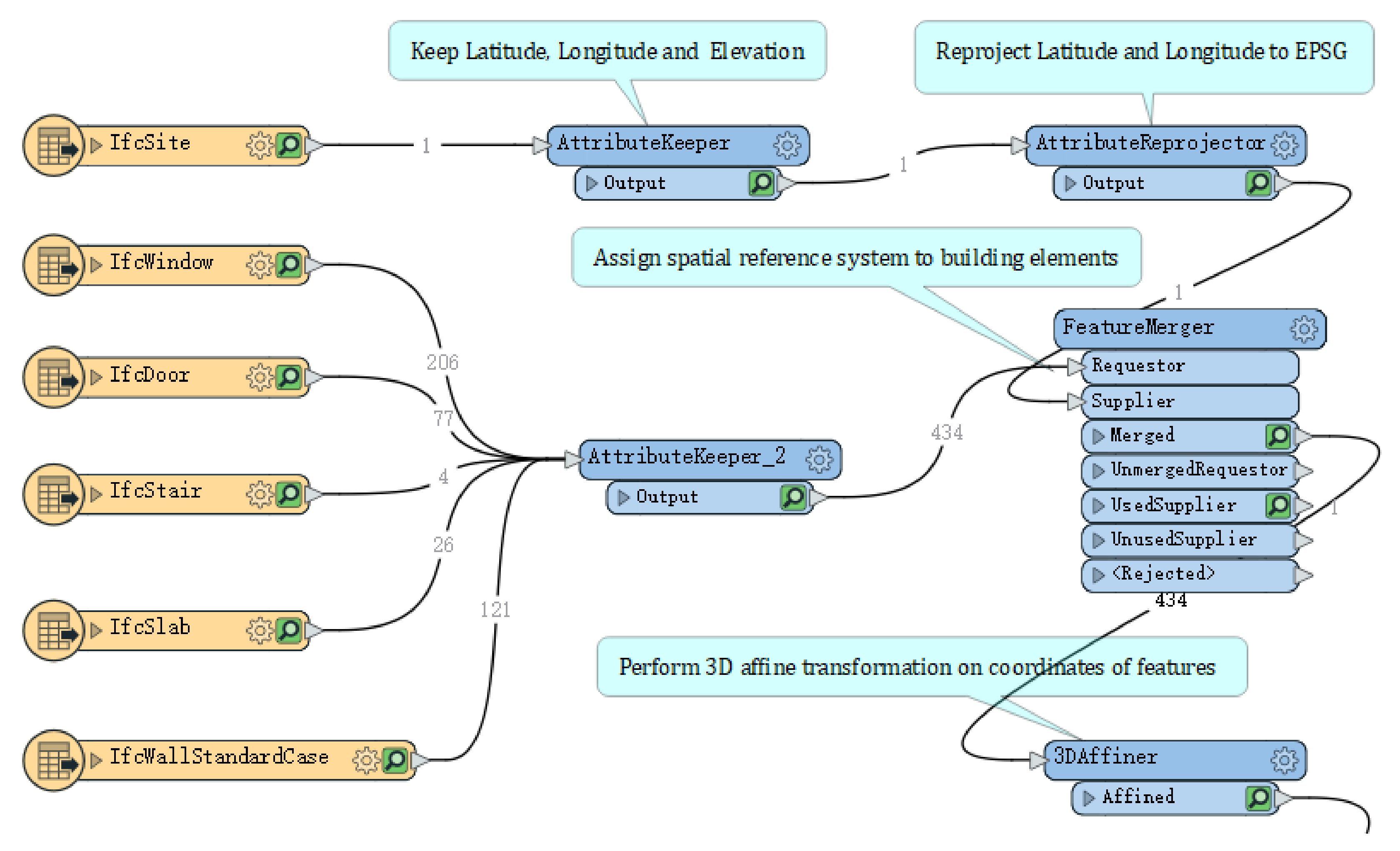
IfcSite provides building location information in the form of latitude, longitude and elevation, while CityGML describes spatial information in the form of a 3D CRS (Coordinate Reference Systems), such as the well-known European Petroleum Survey Group (EPSG); therefore, conversion of spatial reference system is required. The latitude, longitude and elevation of IfcSite are extracted by AttributeKeeper and projected to the target spatial reference system, EPSG: 31,467 by AttributeReprojector. The transformer FeatureMerger is used to merge the coordinate reference information with the building elements, and then 3D affine transformation is performed to obtain the coordinate reference information of the building elements (Figure 18).
  • Extraction of the building components
The extraction of the building components is an important part of data extraction. Building components, such as interior walls, ceilings, floors, doors, and windows, are extracted for the generation of indoor spaces according to the simplified description of the building components in Section 3.2.2. The building components and the layouts of the indoor spaces are different in each story and should be filtered and extracted according to each story.
  • Filtering of the building components
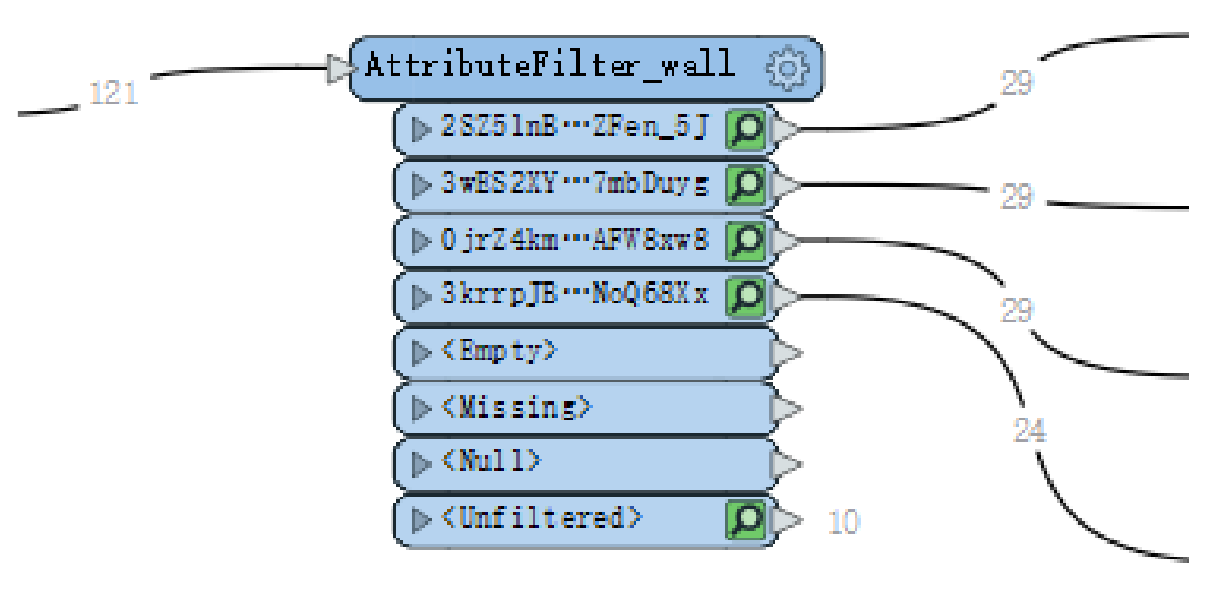
The building components are filtered according to the story where they are. Take the filtering of walls as an example. The IfcWallStandardCase has attributes that contain the ID of its parent class IfcBuildingStory, namely, ifc_parent_id. The walls of each story are filtered out according to the story ID by AttributeFilter, as shown in Figure 19. The same applies to other building components.
2.
Extraction of the building components
As described in Section 3.2.2, the extracted surfaces of the building components, such as floors, ceilings, and walls, are all centered in the original building components, and doors, windows, and walls are in one plane. Since the walls of the building are perpendicular to the floors and ceilings, the following steps are followed to extract the building components in this work.
First, the walls and stairs of a story are processed to extract the 2D center walls and the 2D bounding box, respectively, which are overlaid to generate the final 2D center walls of the story. The doors and windows of the story are projected to a plane to clip the final 2D center walls to generate the 2D doors and windows.
Second, the center positions of the original upper and lower floors (IfcSlab) associated with the story are calculated as the elevations of the ceiling and floor of the story, respectively. Surfaces are constructed by AreaBuilder based on the final 2D center walls and assigned the elevations by 3DForcer to obtain the final ceilings and floors, of which the gml_parent_id is set as gml_id of the building. Note that if the story has adjacent stories, the ceilings of the story will be overlaid on the floors upstairs to meet the maximal segmentation before the final ceilings are obtained. Similarly, the floors of the story should be overlaid on the ceilings downstairs to obtain the final floors. The extractions of the ceilings and floors are shown in Figure 20 and Figure 21, respectively.
Finally, the final 2D center walls are assigned the elevation of the floors, which are extruded by the height of the story to obtain the initial interior walls of the story. The doors and windows are assigned elevations, and extruded by the respective heights to obtain the final doors and windows, which are overlaid with the initial interior walls by SurfaceOnSurfaceOverlayer to obtain the final interior walls. The parent ID: gml_parent_id of the interior walls is set as ID: gml_id of the building, while the parent ID: gml_parent_id of the doors and windows are is set as the ID: gml_id of the interior walls since the doors and windows belong to Openings. The extractions of interior walls, doors and windows are shown in Figure 22.
  • Generation of Indoor Spaces
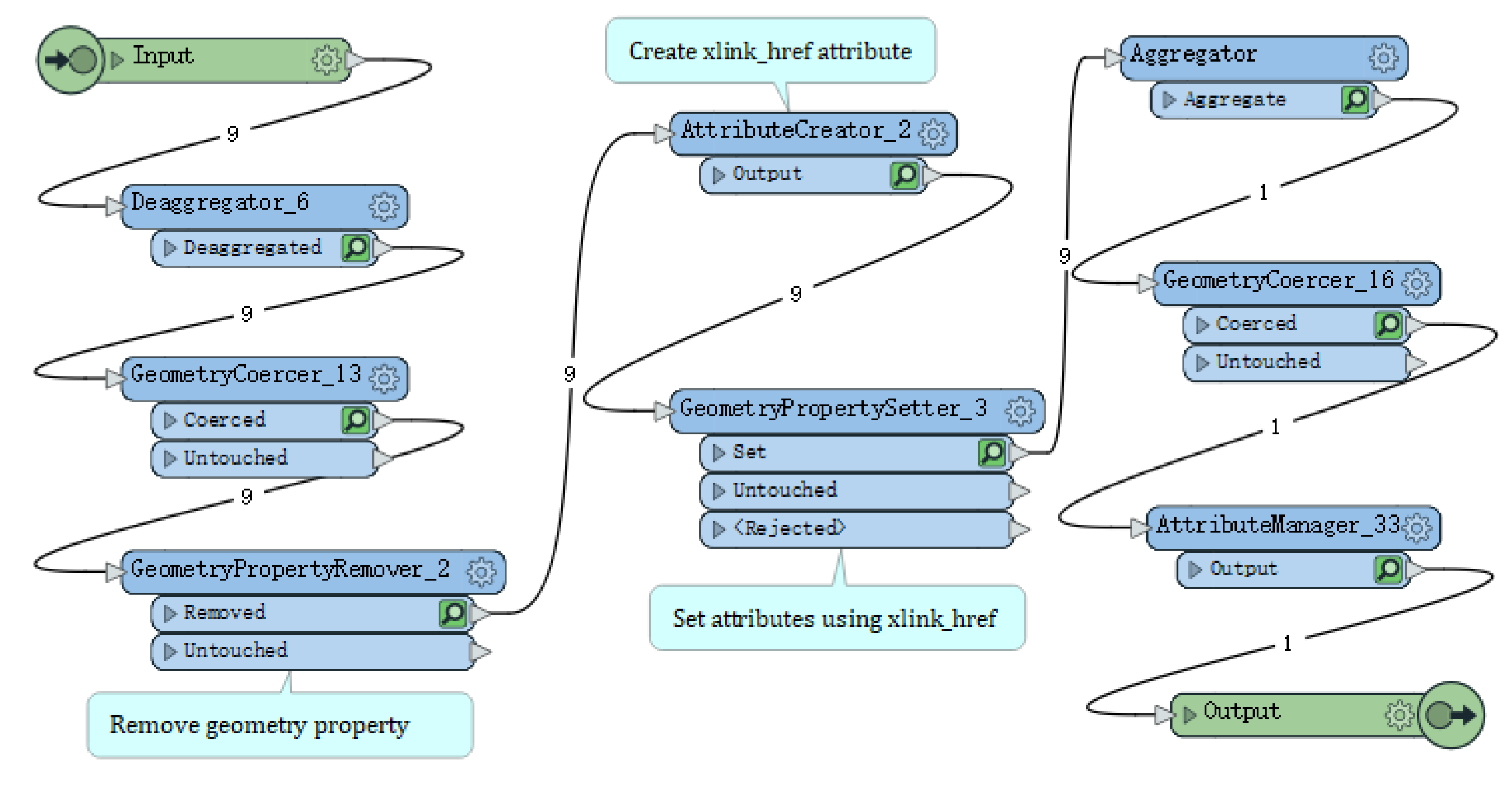
Rooms can be constructed through SolidBuilder using the building components extracted above. However, the solid entities constructed in this way have redundant geometric information instead of being built by CityGML XLinks. Therefore, it is necessary to remove the geometric information and set the xlink_href property on the extracted building components before constructing the rooms. In this work, a customized transformer RoomBuilder is used to implement the construction of each interior space, as shown in Figure 23.

4.3. Results

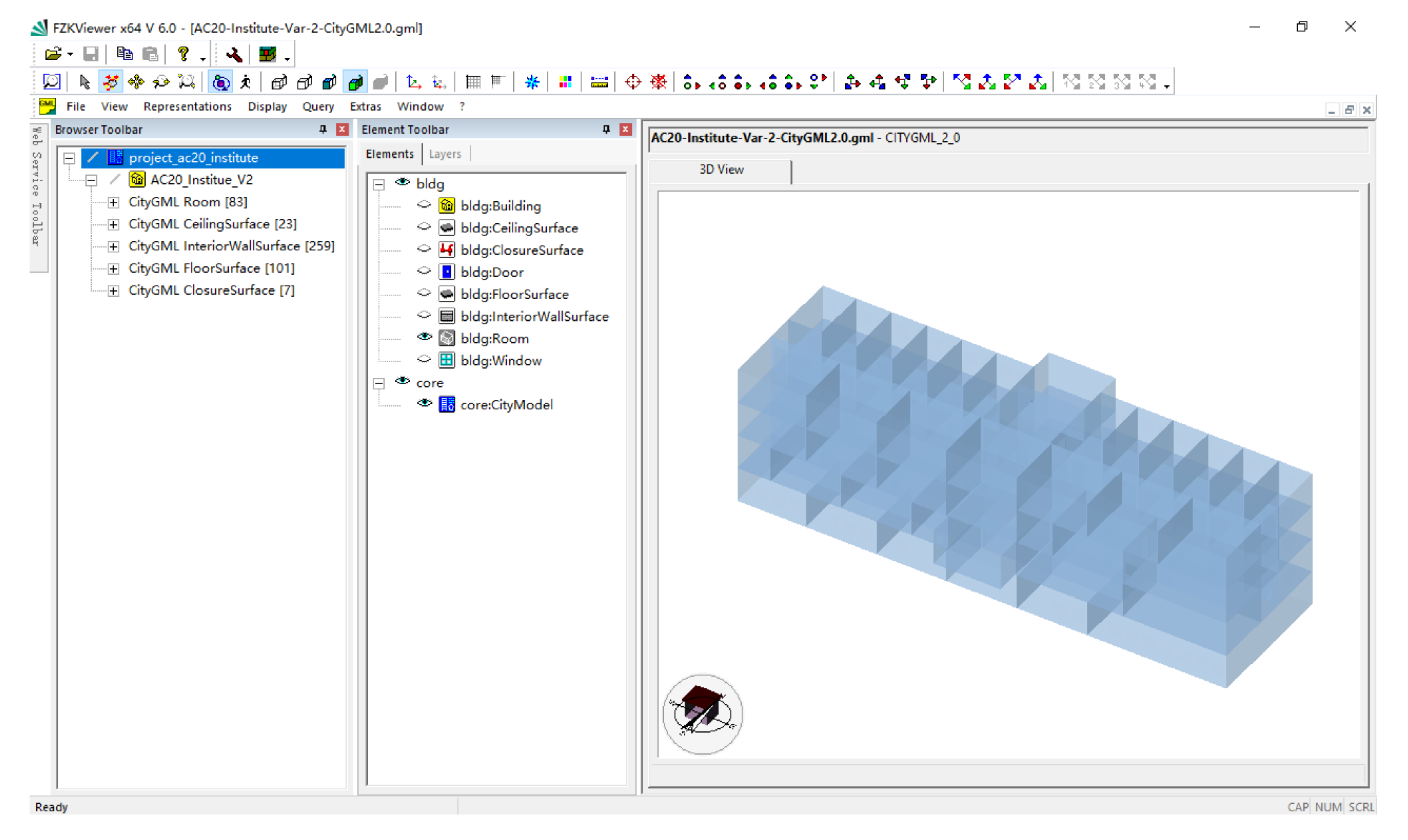
The extracted building components and interior spaces are written to CityGML by the transformer Writer and visualized in FZK Viewer (developed by Karlsruher Univerity of Technology, version 6.0). Figure 24 shows the extracted building elements (ceilings are not shown for visualization purposes) and the number of extracted CityGML classes. Figure 25 shows the interior functional spaces constructed by the extracted building elements using XLinks.
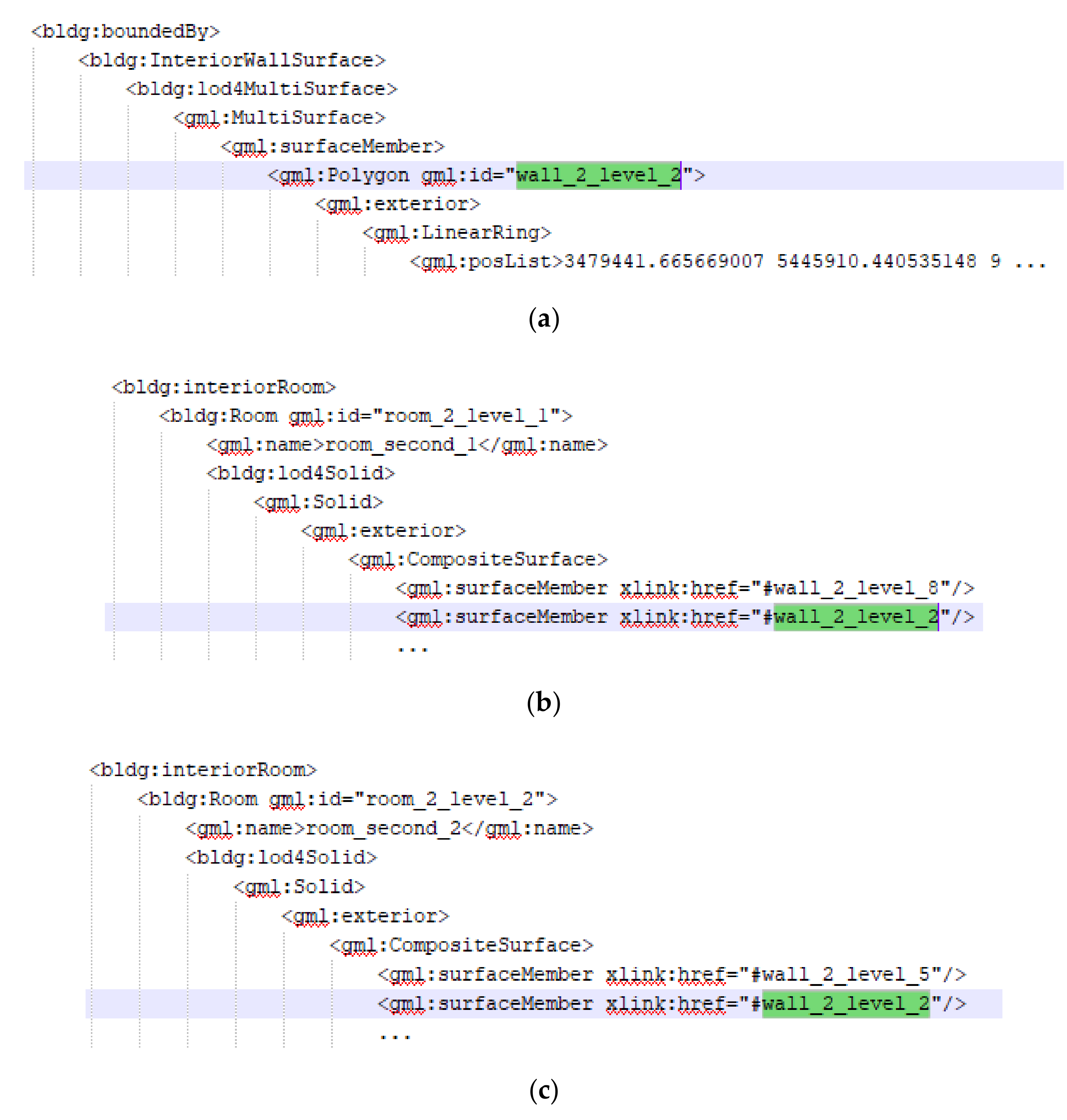
The building component between two adjacent spaces is the common element shared by these spaces. The two spaces reference the shared element using the XLinks to represent the topological relationship and to describe the adjacency. Taking two adjacent rooms “room_second_1” and “room_second_2” as an example, the XML description of the common element interior wall “wall_2_level_2” is shown in Figure 26a, which is referenced by the two rooms using XLinks to describe the topological relationship of the two rooms (Figure 26b,c).

5. Conclusions and Future Work

As the basis for indoor navigation and emergency rescue, a 3D indoor model should be able to provide a variety of indoor spatial information, such as indoor locations, building components, and indoor spatial adjacency relationships. A simplified 3D indoor model that contains accurate indoor spatial geometry information, rich semantic information, and spatial topological relationship information is proposed in this paper to achieve efficient indoor navigation and rapid emergency rescue. The simplified 3D indoor model in this research has the following advantages.
Flexible LOD description for the building interior. Considering that the LODs concept of CityGML2.0 can no longer meet the requirements of emerging indoor applications, the model draws on the LODs concept of CityGML3.0, describing the indoor LOD of buildings in detail, and ignoring the outdoor LOD. The model eliminates the exterior building information that is not of interest to indoor applications, avoids data redundancy, and provides basic data for indoor applications.
Lightweight description for indoor spaces. The building components are simplified in the model, and the geometric properties of the elements are preserved as much as possible. Although the location of the building elements may change after simplification (e.g., replacing the original wall with a center surface), the centered element can represent the original component without loss of accuracy for indoor navigation. Moreover, the original semantic properties of building components are retained, and appropriate semantic properties are assigned to describe the indoor space characteristics, avoiding semantic inconsistency after simplification. Third, the model is beneficial as it describes the adjacencies of indoor spaces. For example, replacing the original wall with a center surface allows to represent the topological relationship of indoor spaces using XLinks, providing basic data for indoor spatial query and path generation.
Facilitating data interoperability. The geometric, semantic, and topological properties of the model follow the CityGML schema, which is based on GML. GML provides a standardized geometry and topology model of geographical features, making it easy to combine CityGML with other geospatial data to facilitate interoperable data exchange.
However, several aspects still need to be investigated further and solved. First, the model provides a simplified description for complex building components and indoor spaces, but does not consider interior facilities, such as furniture. In reality, various facilities and furniture, both movable and nonmovable, are placed in indoor spaces. These furnishings occupy a certain amount of indoor space that is inaccessible, and the available unoccupied space needs to be calculated for indoor navigation and emergency rescue. CityGML 2.0 LOD4 is able to geometrically and semantically describe furniture; however, as mentioned above, all detailed indoor information, including furniture, is represented in LOD4. Additionally, LOD4 describes the location, shape and size of furniture in detail, which is too elaborate for indoor navigation, resulting in data redundancy. Furthermore, some furniture, such as chairs, can move around and thus the unoccupied space will change at any time. Accurately and appropriately describing furniture without data redundancy and representing the mobility of furniture is a major challenge in building 3D indoor models.
Second, the model describes the topological adjacencies of indoor spaces through CityGML XLinks to facilitate the generation of indoor space paths. However, detailed indoor path information has not been provided in the model. On the one hand, indoor navigation requires detailed indoor space information, and on the other hand, the ability to quickly develop suitable indoor paths is needed. An efficient indoor path model is required to provide proper path information for indoor navigation. As a complement to CityGML, IndoorGML describes a network model for indoor navigation. Combining the model proposed in this paper with IndoorGML is a feasible solution. Furthermore, a 3D outdoor model is indispensable which should be combined with indoors for a building. Constructing a full 3D indoor and outdoor model that integrates building spatial geometry information, semantic information, topological adjacency information, and indoor path information to better serve integrated indoor/outdoor applications and provides comprehensive 3D spatial data for smart cities is an urgent task.

Author Contributions

Conceptualization, Q.S. and X.Z.; methodology, Q.S. and X.Z.; formal analysis, X.Z. and D.H.; writing—original draft preparation, Q.S.; writing—review and editing, X.Z. and D.H. All authors have read and agreed to the published version of the manuscript.

Funding

This research was funded by the National Natural Science Foundation of China (Project No. 41971360).

Conflicts of Interest

The authors declare no conflict of interest.

References

  1. Li, W.; Batty, M.; Goodchild, M.F. Real-Time GIS for Smart Cities. Int. J. Geogr. Inf. Sci. 2020, 34, 311. [Google Scholar] [CrossRef]
  2. Jovanović, D.; Milovanov, S.; Ruskovski, I.; Govedarica, M.; Sladić, D.; Radulović, A.; Pajić, V. Building Virtual 3D City Model for Smart Cities Applications: A Case Study on Campus Area of the University of Novi Sad. ISPRS Int. J. Geo-Inf. 2020, 9, 476. [Google Scholar] [CrossRef]
  3. Fellner, I.; Huang, H.; Gartner, G. “Turn Left after the WC, and Use the Lift to Go to the 2nd Floor”—Generation of Landmark-Based Route Instructions for Indoor Navigation. ISPRS Int. J. Geo-Inf. 2017, 6, 183. [Google Scholar] [CrossRef] [Green Version]
  4. Tashakkori, H.; Rajabifard, A.; Kalantari, M. A New 3D Indoor/Outdoor Spatial Model for Indoor Emergency Response Facilitation. Build. Environ. 2015, 89, 170–182. [Google Scholar] [CrossRef]
  5. Ghawana, T.; Aleksandrov, M.; Zlatanova, S. 3D geospatial indoor navigation for disaster risk reduction and response in urban environment. ISPRS Ann. Photogramm. Remote Sens. Spat. Inf. Sci. 2018, 4, 49–57. [Google Scholar] [CrossRef] [Green Version]
  6. Dong, W.; Qin, T.; Liao, H.; Liu, Y.; Liu, J. Comparing the Roles of Landmark Visual Salience and Semantic Salience in Visual Guidance during Indoor Wayfinding. Cartogr. Geogr. Inf. Sci. 2020, 47, 229–243. [Google Scholar] [CrossRef]
  7. Yang, C.; Shao, H.-R. WiFi-Based Indoor Positioning. IEEE Commun. Mag. 2015, 53, 150–157. [Google Scholar] [CrossRef]
  8. Tiemann, J.; Schweikowski, F.; Wietfeld, C. Design of an UWB Indoor-Positioning System for UAV Navigation in GNSS-Denied Environments. In Proceedings of the 2015 International Conference on Indoor Positioning and Indoor Navigation (IPIN), Banff, AB, Canada, 13–16 October 2015; IEEE: Piscataway, NJ, USA, 2015; pp. 1–7. [Google Scholar]
  9. Afuosi, M.B.; Zoghi, M.R. Indoor Positioning Based on Improved Weighted KNN for Energy Management in Smart Buildings. Energy Build. 2020, 212, 109754. [Google Scholar] [CrossRef]
  10. Cui, W.; Liu, Q.; Zhang, L.; Wang, H.; Lu, X.; Li, J. A Robust Mobile Robot Indoor Positioning System Based on Wi-Fi. Int. J. Adv. Robot. Syst. 2020, 17, 1729881419896660. [Google Scholar] [CrossRef] [Green Version]
  11. Xu, H.; Ding, Y.; Li, P.; Wang, R.; Li, Y. An RFID Indoor Positioning Algorithm Based on Bayesian Probability and K-Nearest Neighbor. Sensors 2017, 17, 1806. [Google Scholar] [CrossRef] [Green Version]
  12. Zhou, C.; Yuan, J.; Liu, H.; Qiu, J. Bluetooth Indoor Positioning Based on RSSI and Kalman Filter. Wirel. Pers. Commun. 2017, 96, 4115–4130. [Google Scholar] [CrossRef]
  13. Brown, G.; Nagel, C.; Zlatanova, S.; Kolbe, T.H. Modelling 3D Topographic Space against Indoor Navigation Requirements. In Progress and New Trends in 3D Geoinformation Sciences; Springer: Berlin/Heidelberg, Germany, 2013; pp. 1–12. [Google Scholar]
  14. Eastman, C.M.; Eastman, C.; Teicholz, P.; Sacks, R.; Liston, K. BIM Handbook: A Guide to Building Information Modeling for Owners, Managers, Designers, Engineers and Contractors; John Wiley & Sons: Hoboken, NJ, USA, 2011. [Google Scholar]
  15. Building SMART. International, Industry Foundation Classes (IFC), IFC4.1. 2018. Available online: http://www.buildingsmart.org/standards/ifc (accessed on 20 September 2020).
  16. Isikdag, U.; Zlatanova, S.; Underwood, J. A BIM-Oriented Model for Supporting Indoor Navigation Requirements. Comput. Environ. Urban Syst. 2013, 41, 112–123. [Google Scholar] [CrossRef]
  17. Deng, Y.; Cheng, J.C.; Anumba, C. Mapping between BIM and 3D GIS in Different Levels of Detail Using Schema Mediation and Instance Comparison. Autom. Constr. 2016, 67, 1–21. [Google Scholar] [CrossRef]
  18. Zhu, J.; Wang, X.; Chen, M.; Wu, P.; Kim, M.J. Integration of BIM and GIS: IFC Geometry Transformation to Shapefile Using Enhanced Open-Source Approach. Autom. Constr. 2019, 106, 102859. [Google Scholar] [CrossRef]
  19. Zhu, J.; Wright, G.; Wang, J.; Wang, X. A Critical Review of the Integration of Geographic Information System and Building Information Modelling at the Data Level. ISPRS Int. J. Geo-Inf. 2018, 7, 66. [Google Scholar] [CrossRef] [Green Version]
  20. Wang, T.-K.; Zhang, Q.; Chong, H.-Y.; Wang, X. Integrated Supplier Selection Framework in a Resilient Construction Supply Chain: An Approach via Analytic Hierarchy Process (AHP) and Grey Relational Analysis (GRA). Sustainability 2017, 9, 289. [Google Scholar] [CrossRef] [Green Version]
  21. Gröger, G.; Plümer, L. CityGML—Interoperable Semantic 3D City Models. ISPRS J. Photogramm. Remote Sens. 2012, 71, 12–33. [Google Scholar] [CrossRef]
  22. OGC. City Geography Markup Language (CityGML) Encoding Standard; Open Geospatial Consortium. 2012. Available online: https://www.ogc.org/standards/citygml (accessed on 20 September 2020).
  23. Becker, T.; Nagel, C.; Kolbe, T.H. A Multilayered Space-Event Model for Navigation in Indoor Spaces. In 3D Geo-Information Sciences; Springer: Berlin/Heidelberg, Germany, 2009; pp. 61–77. [Google Scholar]
  24. Kolbe, T.H.; Gröger, G.; Plümer, L. CityGML–3D City Models and Their Potential for Emergency Response. In Geospatial Information Technology for Emergency Response; Taylor & Francis: Abingdon, UK, 2008; pp. 257–274. [Google Scholar]
  25. Löwner, M.-O.; Gröger, G.; Benner, J.; Biljecki, F.; Nagel, C. Proposal for a new lod and multi-representation concept for citygml. ISPRS Ann. Photogramm. Remote Sens. Spat. Inf. Sci. 2016, IV-2/W1, 3–12. [Google Scholar]
  26. Kutzner, T.; Chaturvedi, K.; Kolbe, T.H. CityGML 3.0: New Functions Open Up New Applications. PFG J. Photogramm. Remote Sens. Geoinf. Sci. 2020, 1–19. [Google Scholar] [CrossRef] [Green Version]
  27. OGC. IndoorGML Standard, Version: 1.0.3; Open Geospatial Consortium. 2018. Available online: https://www.ogc.org/standards/indoorgml (accessed on 20 September 2020).
  28. ISO. ISO 19152:2012, Geographic Information-Land Administration Domain Model, 1st ed.; ISO: Geneva, Switzerland, 2012. [Google Scholar]
  29. Rönsdorf, C.; Wilson, D.; Stoter, J. Integration of land administration domain model with CityGML for 3D cadastre. In Proceedings of the 4th International Workshop on 3D Cadastres, Dubai, UAE, 9–11 November 2014; pp. 313–322. [Google Scholar]
  30. Gozdz, K.; Pachelski, W.; Van Oosterom, P.J.M.; Coors, V. The possibilities of using CityGML for 3D representation of buildings in the cadastre. In Proceedings of the 4th International Workshop on 3D Cadastres, Dubai, UAE, 9–11 November 2014; pp. 339–361. [Google Scholar]
  31. Surmeneli, H.G.; Koeva, M.N.; Zevenbergen, J.A.; Alkan, M. Towards integration of LADM and CityGML for the cadastral system of Turkey. Int. Arch. Photogramm. Remote Sens. Spat. Inf. Sci. 2020, 43, 691–698. [Google Scholar] [CrossRef]
  32. Alattas, A.; Zlatanova, S.; Van Oosterom, P.; Chatzinikolaou, E.; Lemmen, C.; Li, K.-J. Supporting indoor navigation using access rights to spaces based on combined use of IndoorGML and LADM models. ISPRS Int. J. Geo-Inf. 2017, 6, 384. [Google Scholar] [CrossRef] [Green Version]
  33. Alattas, A.; van Oosterom, P.; Zlatanova, S.; Hoeneveld, D.; Verbree, E. LADM-IndoorGML for exploring user movements in evacuation exercise. Land Use Policy 2020, 98, 104219. [Google Scholar] [CrossRef]
  34. Thompson, R.; Van Oosterom, P. Modelling and validation of 3D cadastral objects. In Urban and Regional Data Management; Taylor & Francis: Abingdon, UK, 2011. [Google Scholar]
  35. Thompson, R.J.; van Oosterom, P. Validity of mixed 2D and 3D cadastral parcels in the land administration domain model. In Proceedings of the 3rd International Workshop on 3D Cadastres, Shenzhen, China, 25–26 October 2012; pp. 325–344. [Google Scholar]
  36. Ying, S.; Guo, R.; Li, L.; Van Oosterom, P.; Stoter, J. Construction of 3D volumetric objects for a 3D cadastral system. Trans. GIS 2015, 19, 758–779. [Google Scholar] [CrossRef]
  37. Biljecki, F.; Ledoux, H.; Stoter, J. An Improved LOD Specification for 3D Building Models. Comput. Environ. Urban Syst. 2016, 59, 25–37. [Google Scholar] [CrossRef] [Green Version]
  38. Benner, J.; Geiger, A.; Gröger, G.; Häfele, K.-H.; Löwner, M.-O. Enhanced LOD Concepts for Virtual 3D City Models. ISPRS annals of the photogrammetry, remote sensing and spatial information sciences. In Proceedings of the ISPRS 8th 3D GeoInfo Conference & WG II/2 Workshop, Istanbul, Turkey, 27–29 November 2013; pp. 51–61. [Google Scholar]
  39. Löwner, M.-O.; Benner, J.; Gröger, G.; Häfele, K.-H. New Concepts for Structuring 3D City Models–an Extended Level of Detail Concept for CityGML Buildings. In International Conference on Computational Science and Its Applications; Springer: Berlin/Heidelberg, Germany, 2013; pp. 466–480. [Google Scholar]
  40. Biljecki, F.; Ledoux, H.; Stoter, J.; Zhao, J. Formalisation of the Level of Detail in 3D City Modelling. Comput. Environ. Urban Syst. 2014, 48, 1–15. [Google Scholar] [CrossRef] [Green Version]
  41. Tang, L.; Li, L.; Ying, S.; Lei, Y. A Full Level-of-Detail Specification for 3D Building Models Combining Indoor and Outdoor Scenes. ISPRS Int. J. Geo-Inf. 2018, 7, 419. [Google Scholar] [CrossRef] [Green Version]
  42. OGC. CityGML-3.0 Conceptual Model. Available online: https://github.com/opengeospatial/CityGML-3.0CM (accessed on 20 September 2020).
  43. OGC. CityGML-3.0 Encodings. Available online: https://github.com/opengeospatial/CityGML-3.0Encodings (accessed on 20 September 2020).
  44. Kim, T.; Kim, K.-S.; Lee, J. How to Extend IndoorGML for Seamless Navigation between Indoor and Outdoor Space. In International Symposium on Web and Wireless Geographical Information Systems; Springer: Berlin/Heidelberg, Germany, 2019; pp. 46–62. [Google Scholar]
  45. Ladenhauf, D.; Berndt, R.; Krispel, U.; Eggeling, E.; Ullrich, T.; Battisti, K.; Gratzl-Michlmair, M. Geometry Simplification According to Semantic Constraints. Comput. Sci. Res. Dev. 2016, 31, 119–125. [Google Scholar] [CrossRef]
  46. Kim, J.-S.; Li, K.-J. Simplification of Geometric Objects in an Indoor Space. ISPRS J. Photogramm. Remote Sens. 2019, 147, 146–162. [Google Scholar] [CrossRef]
  47. Baig, S.U.; Rahman, A.A. A Three-Step Strategy for Generalization of 3D Building Models Based on CityGML Specifications. GeoJournal 2013, 78, 1013–1020. [Google Scholar] [CrossRef] [Green Version]
  48. Fan, H.; Meng, L. A Three-Step Approach of Simplifying 3D Buildings Modeled by CityGML. Int. J. Geogr. Inf. Sci. 2012, 26, 1091–1107. [Google Scholar] [CrossRef]
  49. OGC. Geography markup language (GML) Encoding Sandard; Open Geospatial Consortium. 2007. Available online: https://www.ogc.org/standards/gml (accessed on 20 September 2020).
  50. Herring, J. The OpenGIS Abstract Specification, Topic 1: Feature Geometry (ISO 19107 Spatial Schema), Version 5. In OGC Document; No. 01–101; Open Geospatial Consortium Inc.: Wayland, MA, USA, 2001. [Google Scholar]
  51. Biljecki, F.; Zhao, J.; Stoter, J.E.; Ledoux, H. Revisiting the Concept Level of Detail in 3D City Modelling. In Proceedings of the 8th 3DGeoInfo Conference & WG II/2 Workshop, Istanbul, Turkey, 27–29 November 2013; ISPRS: Christian Heipke, Germany, 2013; Volume II-2/W1. [Google Scholar]
  52. Amsters, R.; Demeester, E.; Stevens, N.; Lauwers, Q.; Slaets, P. Evaluation of Low-Cost/High-Accuracy Indoor Positioning Systems. In Proceedings of the 2019 International Conference on Advances in Sensors, Actuators, Metering and Sensing (ALLSENSORS), Athens, Greece, 24–28 February 2019; pp. 15–20. [Google Scholar]
  53. IFC. 4 Example, Institute for Automation and Applied Informatics (IAI), Karlsruhe Institute of Technology (KIT). 2017. Available online: http://www.ifcwiki.org/index.php?title=KIT_IFC_Examples (accessed on 20 September 2020).
Figure 1. Five representations of a building in level of detail (LOD)0 to LOD4 [37].
Applsci 10 07218 g001
Figure 2. Representation of topology by XLinks.
Applsci 10 07218 g002
Figure 3. Representation of interior rooms in City Geography Markup Language (CityGML).
Applsci 10 07218 g003
Figure 4. Simplification of walls (2D footprints). (a) Exterior and interior boundary surfaces of a building. (b) A building with irregular outer contours.
Applsci 10 07218 g004
Figure 5. UML diagram of adapted 3D indoor spatial geometry model based on CityGML.
Applsci 10 07218 g005
Figure 6. UML diagram of Simplified 3D Indoor Space Model (3DSISM) based on CityGML.
Applsci 10 07218 g006
Figure 7. Representation of walls in CityGML.
Applsci 10 07218 g007
Figure 8. Simplification of walls.
Applsci 10 07218 g008
Figure 9. Maximal segmentation of surfaces.
Applsci 10 07218 g009
Figure 10. Representation of roofs, ceilings, floors and ground plates in CityGML.
Applsci 10 07218 g010
Figure 11. Simplification of ceilings and floors.
Applsci 10 07218 g011
Figure 12. (a) Sectional drawing of a building. (b) Simplification of roofs and ground plates.
Applsci 10 07218 g012
Figure 13. Maximal segmentation of surfaces.
Applsci 10 07218 g013
Figure 14. Representation of doors and windows. (a) Representation of a window in CityGML. (b) Simplified representation of a window. (c) Simplified representation of a door.
Applsci 10 07218 g014
Figure 15. Simplification of stairs.
Applsci 10 07218 g015
Figure 16. The Building Information Modeling (BIM) model of an office building.
Applsci 10 07218 g016
Figure 17. Setting of attribute data of CityGML classes.
Applsci 10 07218 g017
Figure 18. Transformation of spatial reference system.
Applsci 10 07218 g018
Figure 19. Filtering of walls in each story.
Applsci 10 07218 g019
Figure 20. Extraction of ceilings.
Applsci 10 07218 g020
Figure 21. Extraction of floors.
Applsci 10 07218 g021
Figure 22. Extraction of Interior walls, doors and windows.
Applsci 10 07218 g022
Figure 23. Customized transformer for construction of a room.
Applsci 10 07218 g023
Figure 24. Extracted CityGML dataset based on 3DSISM.
Applsci 10 07218 g024
Figure 25. Indoor spaces constructed by the extracted building elements using XLinks.
Applsci 10 07218 g025
Figure 26. Excerpt from the CityGML dataset of an interior wall shared by two adjacent rooms. (a) XML description of an interior wall “wall_2_level_2”. (b) The wall “wall_2_level_2” is referenced by a room “room_second_1” through XLinks. (c) The wall “wall_2_level_2” is referenced by a room “room_second_2” through XLinks.
Applsci 10 07218 g026
Table 1. Semantic mappings from Industry Foundation Classes (IFC) to CityGML.
IFC TypeCityGML Class
IfcProject (Attribute)CityModel
IfcBuilding (Attribute)Building
IfcSite (Attribute: Latitude, Longitude, Elevation)Location information of the building
IfcWallStandardCase (Geometry)
IfcSlab (Geometry)
InteriorWallSurface
CeilingSurface
FloorSurface
IfcStair (Geometry)ClosureSurface
IfcOpeningElement (Attribute)Attribute information for Openings
IfcDoor (Geometry)Door
IfcWindow (Geometry)Window
Publisher’s Note: MDPI stays neutral with regard to jurisdictional claims in published maps and institutional affiliations.