Article

Hybrid Impedance-Admittance Control for Upper Limb Exoskeleton Using Electromyography

by
Lucas D. L. da Silva
1,*,
Thiago F. Pereira
1,
Valderi R. Q. Leithardt
2,3,4,
Laio O. Seman
1 and
Cesar A. Zeferino
1,*
1
LEDS—Laboratory of Embedded and Distribution Systems, University of Vale do Itajaí, Rua Uruguai 458, C.P. 360, 88302-901 Itajaí, Brazil
2
VALORIZA, Research Center for Endogenous Resources Valorization, Instituto Politécnico de Portalegre, 7300-555 Portalegre, Portugal
3
Departamento de Informática, Universidade da Beira Interior, 6201-001 Covilhã, Portugal
4
COPELABS, Universidade Lusófona de Humanidades e Tecnologias, 1749-024 Lisboa, Portugal
*
Authors to whom correspondence should be addressed.
Appl. Sci. 2020, 10(20), 7146; https://doi.org/10.3390/app10207146
Submission received: 30 August 2020 / Revised: 20 September 2020 / Accepted: 2 October 2020 / Published: 14 October 2020
(This article belongs to the Special Issue Wireless Sensor Networks in Smart Environments)

Abstract

:
Exoskeletons are wearable mobile robots that combine various technologies to enable limb movement with greater strength and endurance, being used in several application areas, such as industry and medicine. In this context, this paper presents the development of a hybrid control method for exoskeletons, combining admission and impedance control based on electromyographic input signals. A proof of concept of a robotic arm with two degrees of freedom, mimicking the functions of a human’s upper limb, was built to evaluate the proposed control system. Through tests that measured the discrepancy between the angles of the human joint and the joint of the exoskeleton, it was possible to determine that the system remained within an acceptable error range. The average error is lower than 4.3%, and the robotic arm manages to mimic the movements of the upper limbs of a human in real-time.

1. Introduction

Exoskeletons are wearable mobile robots that combine various technologies to enable limb movement with greater strength and endurance. These robots are used in several application areas, such as industry [1] and medicine [2]. Industry uses exoskeletons to increase the productivity and safety of workers, enabling them to lift, carry, and operate heavy objects and tools [3], thus reducing risks arising from this handling [4,5]. In the medical field, exoskeletons are used to rehabilitate patients by assisting the execution of repetitive movements, thus reducing the therapist’s workload. The use of the exoskeleton increases the efficiency of treatments for the recovery of neuromuscular functions [6]. Among the different applications in rehabilitation, we can cite the work of Zhang et al. [7], who developed an exoskeleton to assist people with muscle weakness. In [6,8], the authors built exoskeletons for the rehabilitation of arms. Wang et al. [9] focused on helping patients to rehabilitate their hands. These and other applications require techniques and technologies to assess muscle function for subsequent activation of the exoskeleton.
Electromyography (EMG) is one of the available techniques used to monitor muscle function. This technique captures the energy generated by the muscles and provides electrical signals that indicate muscle activation. This type of signal is called electromyographic signal [10], and its intensity is directly related to the amount of force exerted by the skeletal muscles [11,12,13], which are responsible for the movement of the joints and the human posture [10,14]. With the correct interpretation, it is possible to find the user’s movement intentions indicated by the electromyographic signals.
Several works combine EMG with other techniques to control exoskeletons, including neuro-fuzzy [8,15], classifiers and neural networks [16], proportional closed-loop control [4], machine learning [17], cinematics [18], and Kalman filter and Hill model [19]. The use of classifiers enables identifying movements with accuracy above 90% [19]. Neural networks can adapt; however, the complexity grows exponentially with the number of inputs [20]. Fuzzy logic offers simplicity and is tolerant to a certain degree of contradiction in data [20]. Although these works indicate that techniques based on Artificial Intelligence (AI) have the potential to be used in the control of exoskeletons, they require training and have a high computational cost. AI-based systems also tend not to behave well in untrained/modeled scenarios [16,21]. Other problems with artificial intelligence techniques lie in insufficient data acquisition that tends to increase the modeling error.
An alternative to AI techniques relies on the use of control techniques analogous to biomechanics and allows changing the rigidity of the robot so that it behaves as human musculature. Among these techniques, we can highlight the impedance and admittance controls, which perform position control through the forces/torques applied to the mechanical structure. At the impedance level, the actuator reacts to the environment, changes its position, and corrects the error generated by the interaction with the environment [22]. Admittance control acts in favor of this change of position, facilitating the user’s interaction with the robotic structure. This method softens the stiffness of the structure [23], usually taking position or speed into account as control parameters.
This research is inserted in the context above and presents a hybrid control system that combines impedance and admittance controls for an exoskeleton of upper limbs to lift large loads. The admittance control defines the position (posture) that the exoskeleton must assume, while the impedance control corrects changes caused by interactions with loads. In addition to the electromyography signals, the system considers the inclination the limb is in, the degree of inclination of the joints, and the load that the structure is carrying. In this article, we present a proof of concept of a robotic arm with two degrees of freedom built for the evaluation of the proposed control system. Experimental results show that the average error is lower than 4.3%, and the robotic arm manages to mimic the movements of the upper limbs of a human in real-time. In this sense, the methodology here presented can be used to extend and improve existing prototypes, such as the ones presented in [24,25].
The remainder of this article is organized as follows. Section 2 presents concepts in biomechanics, electromyography, and bio-inspired control and discusses related work. Next, Section 3 describes the hybrid control system proposed in this work. Section 4 presents the materials and methods used to implement a proof of concept use designed to validate our proposal. Section 5 presents and discusses the experimental results. Section 6 gives the final remarks.

2. Background

2.1. Fundamentals of Biomechanics

It is necessary to understand how the mechanical structures of the human body act to reproduce the movements generated by the user of an exoskeleton. These concepts are approached by biomechanics, a branch of biophysics that studies the movement in living organisms.
The movements are divided into three planes: sagittal, frontal, and transverse [14,26]. In the sagittal plane, flexion, extension, and hyperextension movements occur. The extension is the movement that returns to the anatomical position, hyperextension is the movement that goes beyond the anatomical position, and flexion is the movement of rotation in the sagittal plane (movement performed by the head, trunk, arm, forearm, hand, and hip). The frontal plane comprises the abduction and adduction movements. Abduction is the movement of a body segment outside the midline of the body, while adduction moves towards the midline. The transverse plane involves rotation movements around the longitudinal axis. Lateral and medial rotations are two types of transverse plane movement. The lateral rotation occurs when the limb moves away from the midline of the body, whereas medial rotation occurs in the body’s midline.
Muscles play a role in the movement, and they are the only tissue capable of actively producing tension [26]. The muscles are responsible for the movement of the body’s appendages, but they can only perform these tasks when stimulated by the nervous system; the muscles and the nervous system form the neuromuscular system [12,26,27].
When a muscle contracts and generates movement, it becomes an agonist [14,26], and several muscles collaborate to produce movement (the main agonist and assistant agonists). A muscle that acts in opposition to the agonist, generating an eccentric contraction, is called an antagonist or opponent. Agonists and antagonists usually position themselves on opposite sides of a joint. Agonists are responsible for accelerating movement, while antagonists perform deceleration, especially in rapid movements. There are two other functions that muscles can assume: stabilization and neutralization. The stabilizing muscles stabilize a part of the body against an internal or external force. Neutralizers are responsible for preventing the function of a muscle when its contraction performs more than one function, for instance a muscle that causes flexion and abduction, and only one of the movements must occur [26].
Figure 1 illustrates the elbow flexion and extension movements. Two main muscles are related to these movements: the biceps and the triceps. The biceps act as the agonist of the flexion movement and antagonist of the extension. The triceps, in turn, play the inverse role of the biceps in each of these movements.

2.2. Electromyography

The intensity of an electromyographic signal is directly related to the amount of force exerted by the skeletal muscles [11,12,13]. With the correct interpretation of the electromyographic signals, the exoskeleton control system can identify the user’s movement intentions.
The two basic EMG techniques are intramuscular and surface. The former uses invasive needle-based electrodes, whereas the latter, also known as sEMG, uses non-invasive surface electrodes. The advantage of intramuscular EMG is that signal acquisition is less susceptible to interference than sEMG [13,28], which enables obtaining information from smaller muscles or those located below other muscles [10,13]. The advantage of sEMG lies mainly in the fact that it is non-invasive. Examples of the use of sEMG are found in studies that monitor signals to control exoskeletons for arms [4,8,11,16,17,19], hands [9], wheelchair [15], and knee [29]. In [3], the state-of-the-art on lower limb exoskeletons is analyzed.

2.2.1. Positioning of Electrodes

The electrodes need to be placed in order to find the signal of interest, and it is necessary to identify the region in which the electrode will achieve the best performance in the signal acquisition process [12,27]. Additionally, it is necessary to know if this region is of general placement, in which there is more than one muscle group, or of specific placement, in which the electrode will capture only one muscle group or muscle [12]. Finally, it is necessary to consider some essential parameters, such as the purpose of the muscle, the insertion of the muscle, and the innervation [12]. The purpose of the muscle is the relation of movement effected by the contraction. The insertion is where the muscle is fixed, and it is an indispensable parameter to identify the direction of the fibers to align the surface electrodes with the fibers. Finally, innervation is the origin of the contraction command signal, and it is essential information for the specific placement.

2.2.2. Characteristics of the Electromyographic Signal

The properties of the electrical signal generated by the contraction vary according to the muscle [12,13]. Fast contraction muscles reach maximum tension in one-seventh of the time of a contraction muscle [12,27]. The myoelectric signal occurs within the range of 0–1000 Hz, with most of the signal of interest being between 25 and 500 Hz [12,13,27]. Electromyography devices use low-pass and high-pass filters to ensure the capture of the correct frequencies of the electrical signals generated by the muscles. These filters remove noise and interference produced by the measuring device [12,13,27].
The electromyographic signal can be used in three ways: raw, rectified, and integrated. Raw EMG performs the pure reading of the signal and is typically used in the diagnosis of diseases that affect the muscles or in classifications that consider the frequency of the signal [27]. Rectified EMG converts the raw signal to a single polarity signal, which is typically positive to ensure that the signal does not average to zero. This approach is used in the same applications as the raw EMG. [12]. Finally, the integrated EMG performs the peak-to-peak linearization of the wave and is used to measure muscle effort. This approach is also used in systems that process EMG signals with low computational cost [27].

2.3. Bio-Inspired Controls

Bio-inspired controls are controls that aim to imitate the form of human interaction. The impedance and admittance controls are opposed in concept. The former aims to prevent the environment from disturbing the trajectory, whereas the latter aims to allow interaction [22,30].
The impedance control establishes a dynamic relationship between the interaction force and the position error, correcting the robot’s position errors by increasing the force exerted [22]. This control is defined by (1)
m d ( x ¨ x r ¨ ) + b d ( x ˙ x r ˙ ) + k d ( x x r ) = f e
where m d b d , and k d are the desired impedance coefficients that regulate the performance of the controller, m is the mass of the system, b is the damping coefficient, k is the rigidity of the system, x is the real position, x r is the reference position, and f e is the external force. In this type of control, the force exerted is considered a variable with a high degree of priority. A practical example is in an environment in which robots work together with humans [30].
Admittance control relies on allowing movement, so the actuator changes its position according to the inputs [22]. The controller tries to smooth the source from the rigid position, responding to the forces of interaction and introducing a deviation from the desired movement [22]. In this way, the electromyographic signals are used at the inputs as a force applied to the exoskeleton position [31]. Admittance control is defined by (2)
u = k p ( x r x ) + k v ( x r ˙ x ˙ )
where u is the input control, k p is the position constant, and k v is the speed constant.

2.4. Related Work

Several studies reporting the implementation and evaluation of control systems for robotic arm exoskeletons are found in the literature. Below, we discuss some of these works, which are summarized in Table 1.
Li et al. [32] presented a bio-inspired control with the use of impedance control based on stiffness. The work relates human stiffness to that of the exoskeleton. The authors used a neural network to update the coefficients at run time, and the system measured the trajectory according to the user’s stiffness variation. The control estimated the trajectory for the shoulder and the elbow, and the error obtained was similar for both estimated joints.
In [33], the authors developed a control system based on linear/non-linear cascade regression to activate an arm exoskeleton (shoulder, elbow, and wrist) applied in rehabilitation. The authors extracted the characteristics of the signals with a focus on acquiring amplitude and performing self-regression. The experiments carried out had two groups of participants, one composed of users who had suffered a cerebrovascular accident (CVA) and the other composed of users without a history of stroke. The system achieved a similar performance with the two groups of participants in estimating the movement of the arm’s joints (shoulder, elbow, and wrist).
The authors of [34] developed a control for arm exoskeleton in which the prototype received the commands from a PC via wireless communication. The authors extracted the electromyographic signals in the time, frequency, and time–frequency domains and used the data collected to train a backpropagation neural network (BPNN). The proposed solution uses an embedded microprocessor to capture the signals and command the actuators; the PC processes the measured signal and defines the movement to be performed by the robotic arm. The authors assessed the position estimate using the elbow joint. Despite occasional errors, with peaks of up to 30%, the system achieved a good average result.
In [35], the authors developed a control for elbow exoskeleton using BPNN. They extracted information on the frequency and amplitude of the signal and measured the accuracy in different scenarios. They also considered three situations of visual focus of attention of the user. Their goal was to assess the impact of the control estimate the movements with the user paying attention or not. The system was tested on the elbow joint, and the experiments showed that the control estimate improved with the lack of the user’s attention to the movements.
As Table 1 shows, our work stands out from the others for emphasizing implementation using embedded computing and employing a control technique that has a lower computational cost for defining the control parameters, enabling implementation in low-cost processors for real-time execution. This approach facilitates the construction of a robotic arm that does not depend on a PC for operation.

3. Control System

In this work, we propose a hybrid control system for a robotic arm that combines impedance and admittance controls to determine the trajectory and correct the trajectory error when interacting with objects. The system uses simplified versions of the control equations described in Section 2.3 for implementing a real-time control system.
It is worth noting that the electromyographic signal is the body’s control signal. Thus, we can assume that the control of speed and strength is contained in the EMG signal. Based on this assumption, the proposed admittance control seeks to decide the position that the electromyographic signal represents, while the impedance control aims to deal with the interaction of the robotic arm with the environment to correct its trajectory. The following subsections describe the proposed controls and how they interact.

3.1. Admittance Control

In the proposed system, the admittance control calculates the desired angle θ x which applying (3)
θ x = θ x 1 + k e × ( S a g S a n ) cos ( θ x 1 + θ a j ) × K g × 2 s a g
where θ x 1 is the previously calculated angle, k e is the electromyography constant, S a g is the value of the normalized agonist signal, S a n is the normalized antagonist signal, θ a j is the angle of the anterior joint, and k g is the gravitational constant. k e defines a gain of relevance to the normalized electromyographic signal. Following biomechanics, a more developed musculature generates more strength than a person with less developed musculature. Thus, to perform the same movement, people with more developed muscles need to apply less force to obtain the same result. This coefficient adjusts the control according to the user’s strength because the more muscle, the more is the myoelectric energy obtained by the EMG sensor.
This model seeks to transform the electromyographic signal into motion. In the second term of (3), k e increases or decreases the system’s response to the signal, while ( S a g S a n ) determines the direction of movement. The third term of (3) seeks to support the arm’s position after a movement made by the user. In this term, k g assigns speed of response to the lack of electromyographic signals ( S a g and S a n ), so the product k g × 2 s a g mimics the effect of gravity on the arm.

3.2. Impedance Control

The impedance control calculates the angle change generated by the interaction with the environment in each joint of the robotic arm. The controller reads a force sensor located at the end of the arm, which measures the force of some load (i.e., the mass) suspended by the robotic arm (the environment). The controller then calculates the necessary corrections and drives the joint servo motors to respond to the user’s movement. The definitive angle θ d for each joint is given by (4)
θ d = θ x + k c × cos   θ p j + θ x × m
where θ x is the desired angle, k c is the correction constant, θ p j is the angle of the back joint, and m is the mass value measured by the force sensor. The value of θ d is slightly different from θ x to correct the effect of load on the exoskeleton joint. k c is responsible for defining the change in angle according to the load. The term cos ( θ p j + θ x ) seeks to identify the contribution of load to this change in angle. k c is the constant that relates the interference with the environment and the change in position. In servo motor applications, the impedance control makes a fine adjustment, changing the final angle very little. This adjustment is essential to maintain the precision in the linear force of the motor.

3.3. Integration

The admittance control system inputs are signals that indicate the position change to be performed. The admittance control then modifies the angle of the joints to mimic the user’s movement. This controller considers the value calculated in the previous execution so that the movement is accurately mimicked. In turn, the impedance control considers the forces that act against the movement and changes the forces applied to the motor to correct the position shift caused by the load suspended by the arm. Figure 2 presents a diagram block that represents the interface and main blocks of the proposed hybrid control.

4. Materials and Methods

4.1. System Architecture

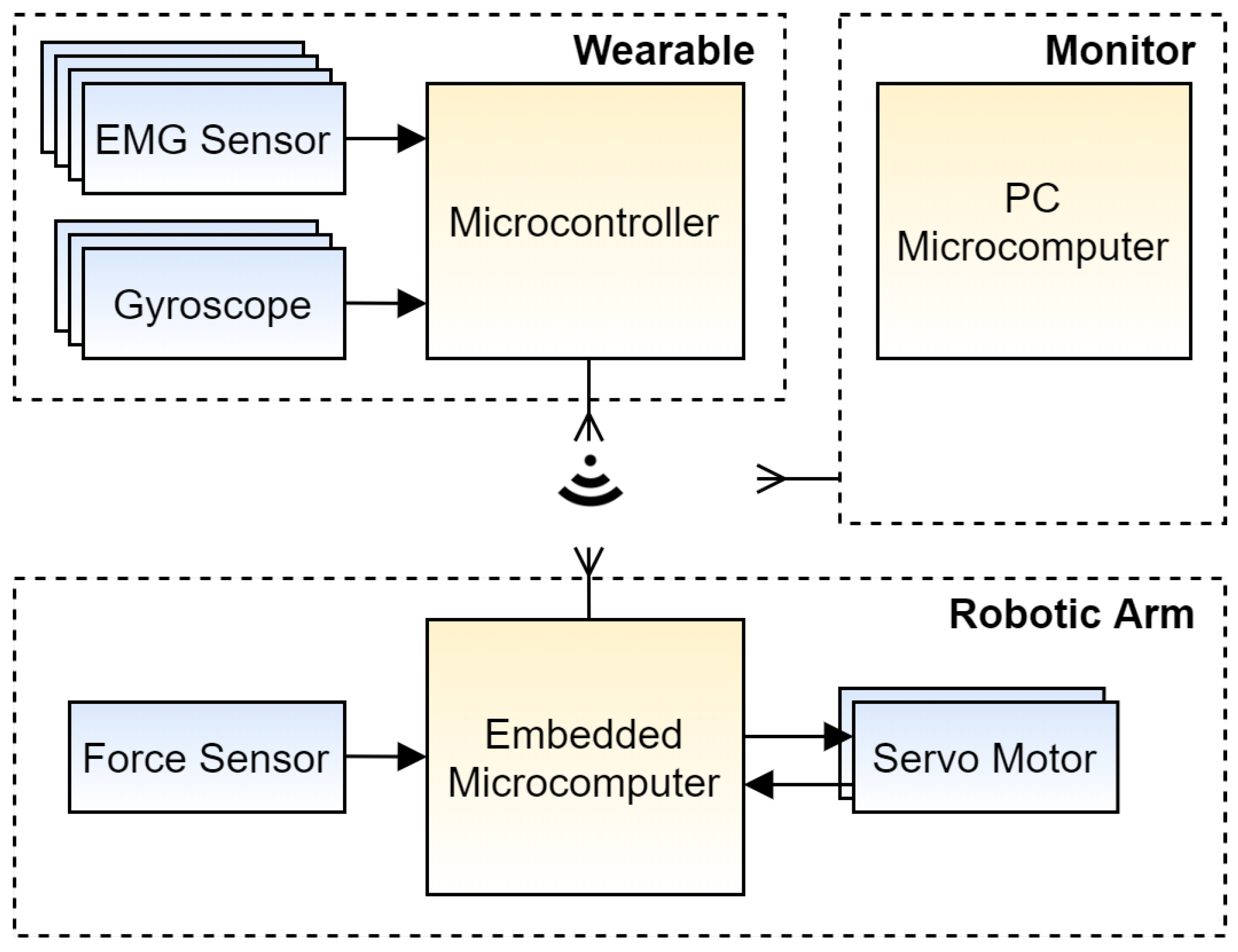
Figure 3 describes the architecture designed to implement the proposed solution, which comprises three subsystems. The first subsystem is a wearable suit that integrates EMG sensors, gyroscopes, and a microcontroller. It captures the user’s arm movement and executes the admittance control. The second subsystem is the robotic arm that integrates an embedded computer, a force sensor, and two feedback servo motors. It receives the movement information computed by the admittance control, reads the force sensor, and activates the servo motors. The last subsystem is a microcomputer that performs the telemetry of the inputs and outputs of the other two subsystems, displaying charts for real-time analysis. Both subsystems communicate through Wi-Fi.

4.2. Materials

We employed several components to build and evaluate the proposed robotic arm. When choosing the materials, we prioritize the lowest cost components that met the project’s requirements. Microcontrollers were selected due to their high availability in the market and the amount of documentation available. The choice of servos was due to the torque/force ratio sufficient so that the structure’s weight did not impact the performance of the robotic arm. All these components—including the sensors—are easy to find in the current market, facilitating the reproduction of the proposed robotic arm. The bill of materials (BOM) used includes:
  • EMG Sensor: MyoWare Muscle Sensor Development Kit, an Arduino-powered sensor kit from Advancer Technologies. The kit also includes circuitry boards to measure the filtered and rectified electrical activity of a muscle [36]. The MyoWare sensor has an input impedance of 110 G Ω and can operate with an input voltage ranging from 2.9 to 5.7 V. It has a potentiometer with resistance ranging from 0.01 to 100 k Ω to adjust the gain at the outputs. The sensor has two outputs that present the integrated and rectified electromyographic signal.
  • Force Sensor: A 0.5" Force Sensitive Resistor (FSR) that senses applied force in the range from 100 g to 10 kg. It varies its resistance according to the pressure applied to the sensing area [37].
  • Gyroscope: MPU-6050, a motion-tracking device that combines a 3-axis gyroscope, a 3-axis accelerometer, and a Digital Motion ProcessorTM in a small package [38].
  • Servo Motor: Datan Analog S1213, an analog feedback servo providing a torque of 6.5 kg*cm with a speed of 0.21 s/60 . This device provides feedback (potentiometer wiper) line that enables reading the servo’s position through an analog interface [39].
  • Microcontroller: ESP32-DevKitC V1 from Espressif, a low-footprint development board which integrates a 32-bit microcontroller (ESP32) and a 2.4 GHz Wi-Fi circuitry, running C code on bare metal [40]. ESP is an acronym for Espressif.
  • Embedded Microcomputer: Raspberry Pi 3 Model B, a single-board computer with wireless LAN and Bluetooth connectivity, running C code on Raspberry Pi OS [41].
  • PC Microcomputer: A laptop computer with an Intel i5 4210U processor and 12 GB of RAM.

4.3. Methods

This section presents the methods used in the development of the proposed hybrid control system. The signal capture uses EMG sensors to read myoelectric signals and gyroscopes to know the position of the user’s joints. ESP32 performs the admittance control system, while the Raspberry Pi 3 runs the impedance control system. The PC microcomputer monitors system operation in real-time for analysis.

4.4. Signal Capture and Processing

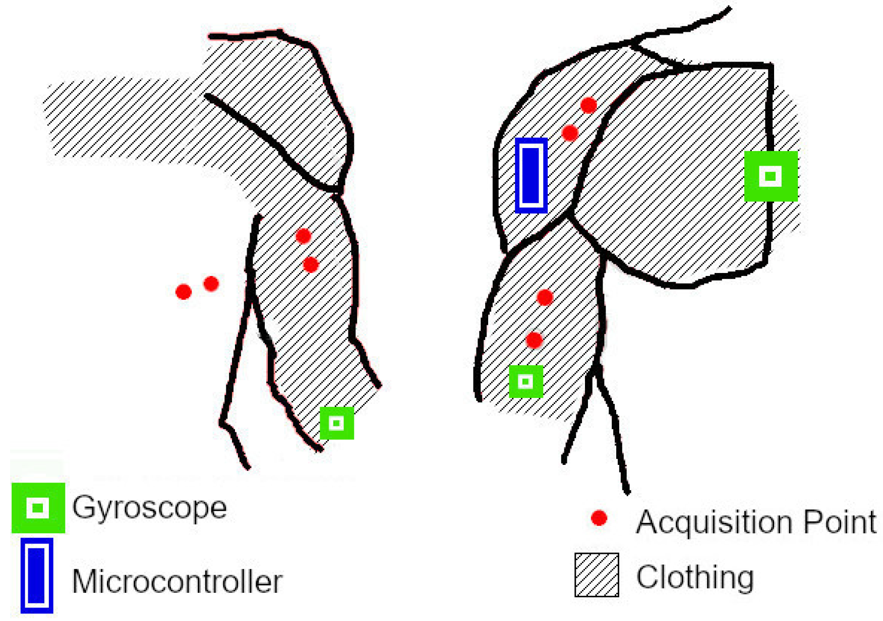
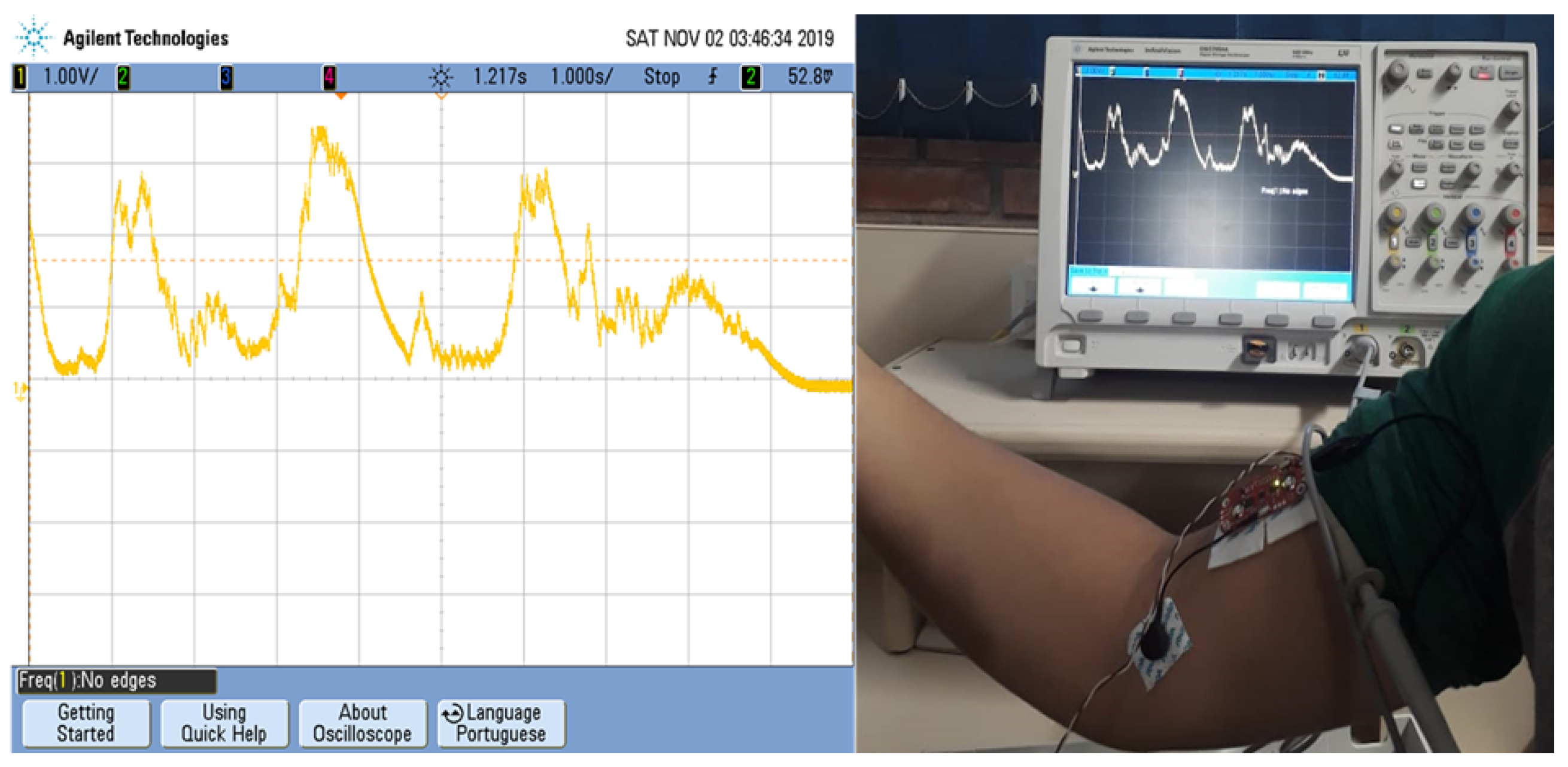
We identified the muscles involved in the movement of the upper limbs and the correct location for the acquisition of electromyographic signals based on the literature [12,27]. Figure 4 identifies the chosen points which were: (i) latissimus dorsi, to identify shoulder extension; (ii) anterior deltoid, for shoulder flexion; (iii) biceps brachii, for elbow flexion; and (iv) triceps, for elbow extension. EMG sensors capture signals and filter surface noise with a Common-mode Rejection Ratio (CMRR) circuit. Figure 5 shows a test that exemplifies the reading of the output voltage of the muscle contraction sensor. The sensor delivers the electromyographic signal appropriately amplified to the analog-to-digital converter (ADC) of the microcontroller.
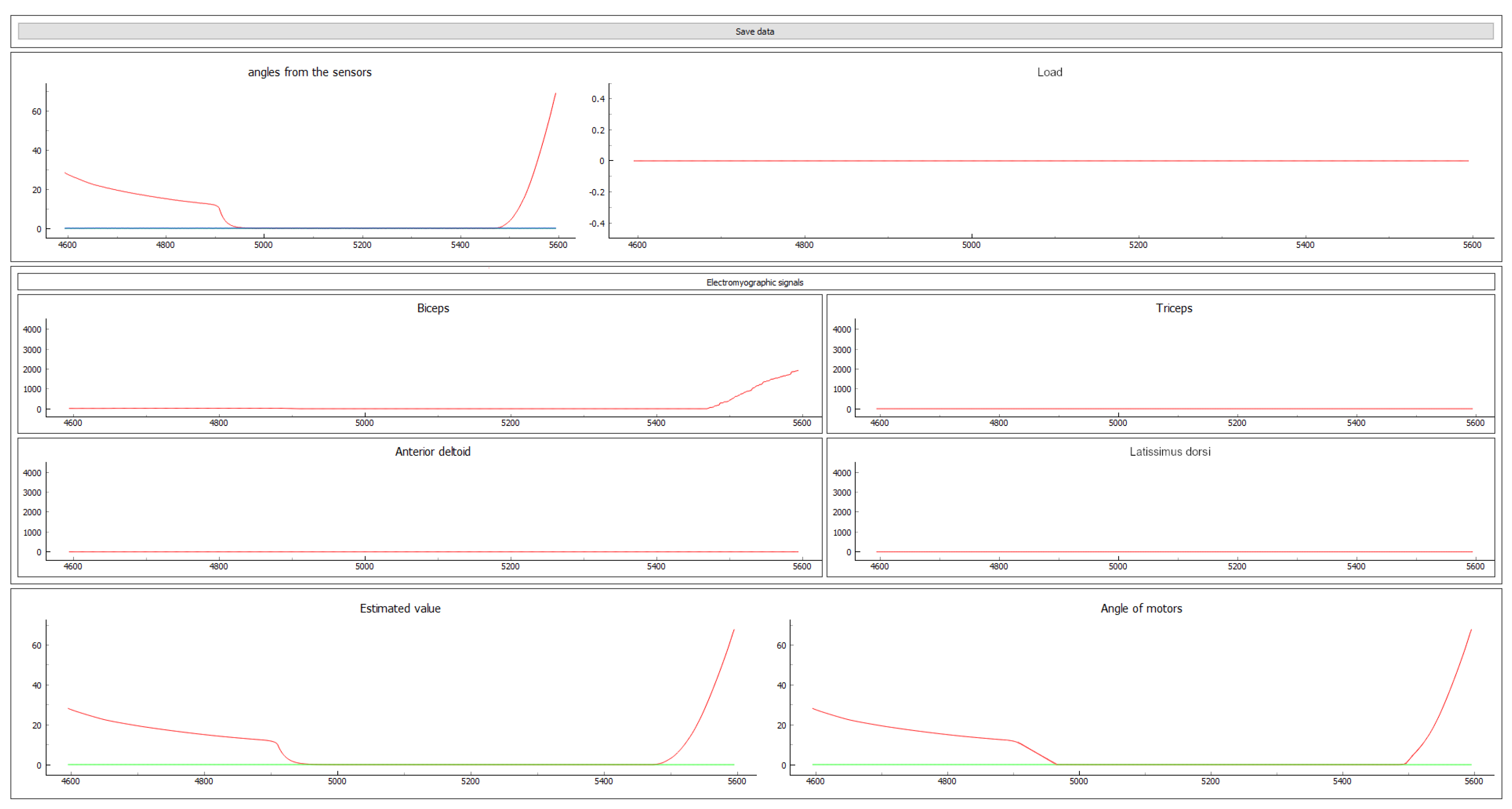
The ESP32 microcontroller captures the EMG signals and angles of the gyroscopes, performs the admittance control, and sends its output to the Raspberry Pi 3 via Wi-Fi, which runs the impedance control algorithm. ESP32 also broadcasts the values of the signals collected through MQTT (Message Queuing Telemetry Transport) communication protocol for the PC microcomputer to display them in real-time for analysis. Figure 6 presents the interface of a program developed for monitoring the system in real-time. The figure shows the values of the angles of the user’s joints in the upper left corner and the mass of the load that the arm is supporting in the upper right corner. Below, the four charts show the values of the electromyographic signals. At the bottom, the two charts present the inductance control output and the feedback receiver from the servo motors.
The example in Figure 6 illustrates a sequence of unloaded elbow movements. The user maintains an upright posture, and the shoulder joint is relaxed. In the first graph, we can see the angles acquired by the gyroscopes. The blue line refers to the shoulder joint, which remains at 0 throughout the observed period as the user does not rotate that joint. The orange line represents the elbow joint, and we can see the variation of the angle measured by the gyroscope. Initially, the user has the elbow slightly flexed (angle close to 30 ) and then performs a slow extension movement. Next, the user keeps the arm extended (angle equal to 0 ) for a while, and flexes the elbow quickly to an angle greater than 70 . From the last two graphs, we can see that the control system’s output and the feedback from the servo motors reproduce these movements in real-time. Concerning the other graphs, we can see that the load graph remains at 0 g because the experiment was conducted without load. The four central graphs present the EMG signals read by the ESP32 microcontroller. As its ADC has a 12-bit resolution, the measurements range from 0 to 4095; these measurements are integrated EMG values, an approach used in low-cost systems [27]. The graphs concerning the EMG signals show that the triceps, anterior deltoid, and latissimus dorsi muscles are relaxed, whereas the biceps perform a low-intensity contraction at the moment of the elbow flexion.

4.5. Proof of Concept

We developed a proof of concept (POC) for validation of the proposed solution. It is composed of two separate parts: (i) a wearable suit, which encloses the ESP32 microcontroller, the EMG sensors, and the gyroscopes; and (ii) a reduced-scale robotic arm, which comprises the Raspberry Pi 3, the force sensor and the servo motors.
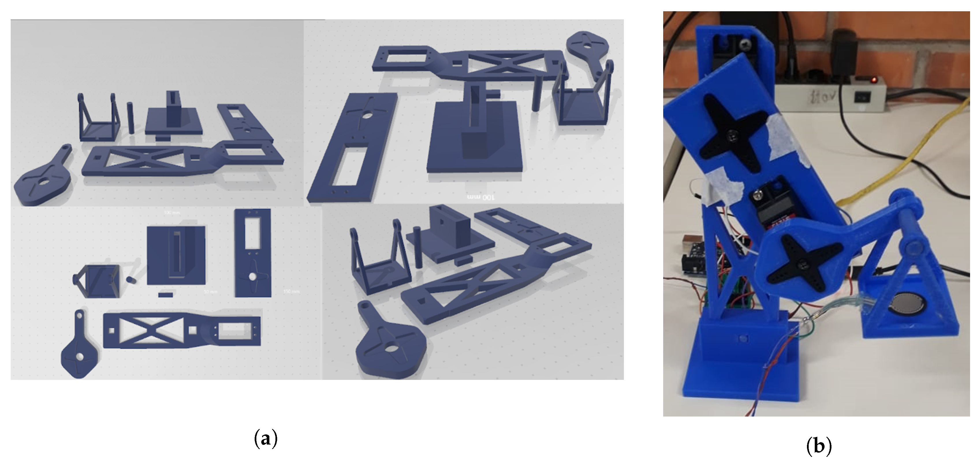
We used a CAD (Computer-aided Design) tool to model the robotic arm and measurements based on the Vitruvian proportion with a 1.72 m man. The model’s arm and forearm measurements are 320 and 253 mm long, whereas the dimensions of the robotic arm’s parts are 65 and 51 mm. We produced these parts in PLA (Polylactic Acid) using a 3D printer. The printed parts have holes for fixing the motor case, and mechanical fittings secure the servo motors’ control horns. Figure 7 shows: (a) the 3D modeling of the parts that compose the mechanical structure of the robotic arm; and (b) the physical implementation of the POC. In Figure 7b, we can note the force sensor used to measure the mass of the load suspended by the arm and the servo motor of the elbow articulation.

4.6. Calibration

4.6.1. Normalization

We employed a variation of the MVC (Maximum Voluntary Contraction) method to calibrate the system. MVC measures the maximum EMG value that the user can generate [32]. The proposed variation, which we call contraction for maximum angle (CMA), measures the maximum value for the EMG signal the user generates when contracting a muscle to the joint’s limit in the shortest time. This measure becomes the reference for normalizing intermediate values. CMA method makes the participants produce acceptable entries for the system, even if they have anatomical differences. The average error is lower than 4.5%, and the robotic manages to mimic the movements of the upper limbs of a human in real-time.
The experiment carried out consisted of performing the elbow and shoulder extension and flexion movements; these movements being ordered in biceps, triceps, anterior deltoid, and latissimus dorsi. In the first execution, the elbow flexion and extension movements were performed as quickly as possible. In the second execution, the user extended and flexed the shoulder.

4.6.2. Control Coefficients

We set k g to 9.8 because it is the approximate gravity value. We carried out experiments to evaluate the angle reported for the robotic arm to reach and the servo motor’s feedback using loads with different masses. k e defines gain in the normalized electromyographic signal. We defined its value to 1.25 experimentally based on trial and error with visual feedback. It must be individually adjusted for each user, taking into account the user’s strength (i.e., the necessary force that the user applies to move the load). k c is the coefficient related to the interference with the environment and the change in position. At this point in the research, we defined its value to 0.10 based on trial and error to become more consistent with the values presented by the measuring equipment. The automatic definition of this coefficient is a work to be developed in future applications.

4.6.3. Influence of Structure Weight

Regarding the structure weight, about 15 g add up to the load. However, considering the weight of the elbow joint structure, the maximum deviation generated is 0.0098 . For the shoulder, the maximum deviation considered is 0.0588 . Given the low magnitude of the deviations, they were disregarded. Notice that, since the digital-to-analog converter (DAC) has a 12-bit resolution, the angle variation to be recorded is 0.043 .

4.7. Gyroscope Error

We performed tests with the POC in which the gyroscope was placed on the axis of rotation. The experiments showed that the gyroscope varied from 1 to + 1 when at rest and from 0 . 5 to + 0 . 5 when in motion. We then applied a five-position moving average filter to reduce the average error to 0 . 1 .

5. Experimental Results

We tested the POC using the following values for the coefficients of the control systems: k e = 1.25, k g = 9.8, and k c = 0.1. The tests comprised a series of movements during which we monitored the angles of the user’s joints, which indicate the desired positioning and the robotic arm’s angles. First, we performed a no-load test to verify the admittance system. Afterward, we carried out the experiments described in the following subsections. The study was conducted in accordance with the Declaration of Helsinki, and the protocol was approved by the Ethics Committee of University of Vale do Itajaí (Project Identification code: 38698920.0.0000.0120).

5.1. Experiment 1: One Degree and no Load

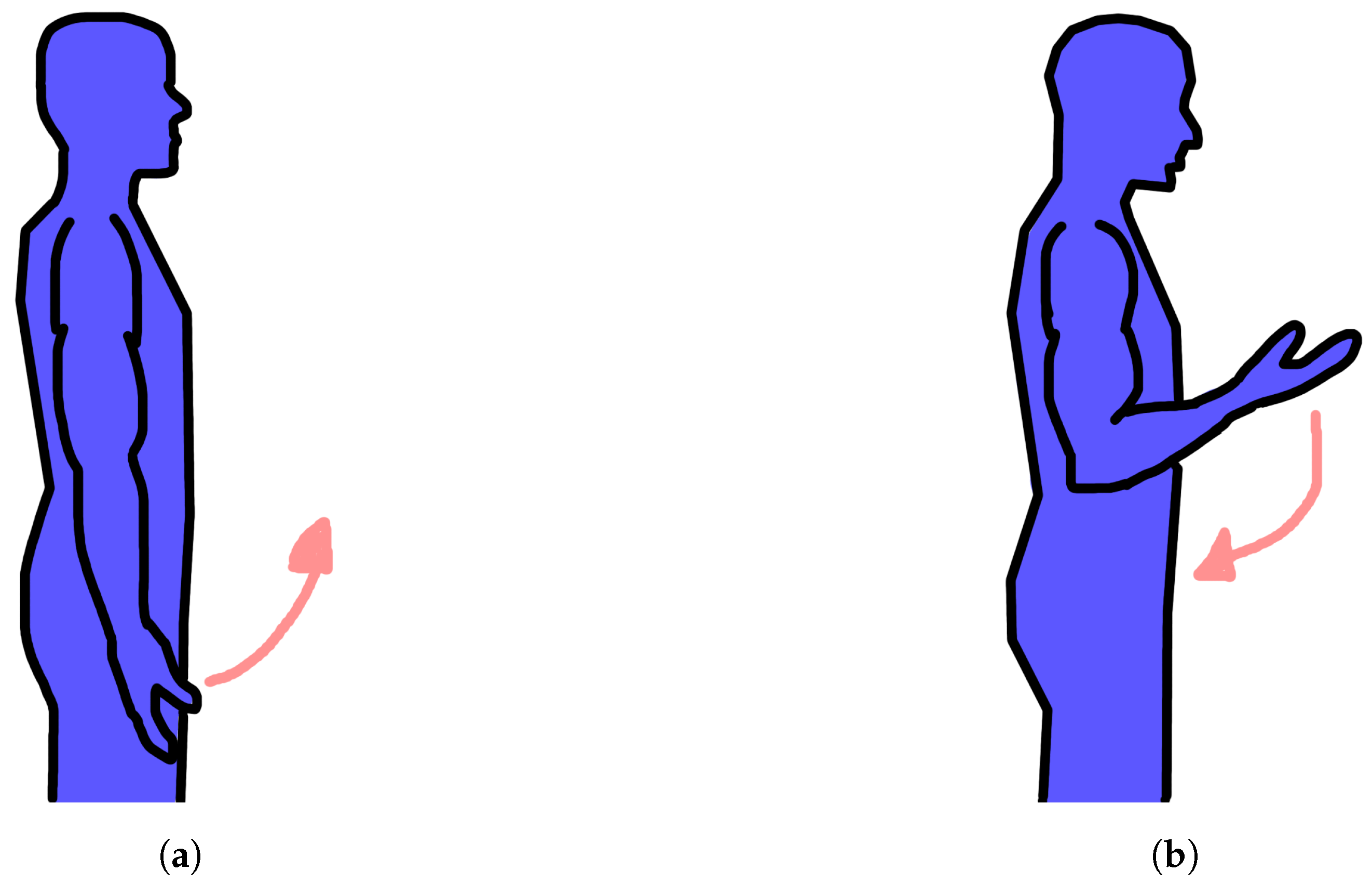
In this experiment, the user performed the flexion and elbow extension movements illustrated in Figure 8. First, with an upright posture and the arm relaxed, the user achieved almost complete flexion. After that, he/she relaxed the gill biceps, performing the elbow extension. The user then performed another bicep contraction but aiming to reach a right angle compared to the relaxed arm. Finally, he/she performed a less intense contraction.
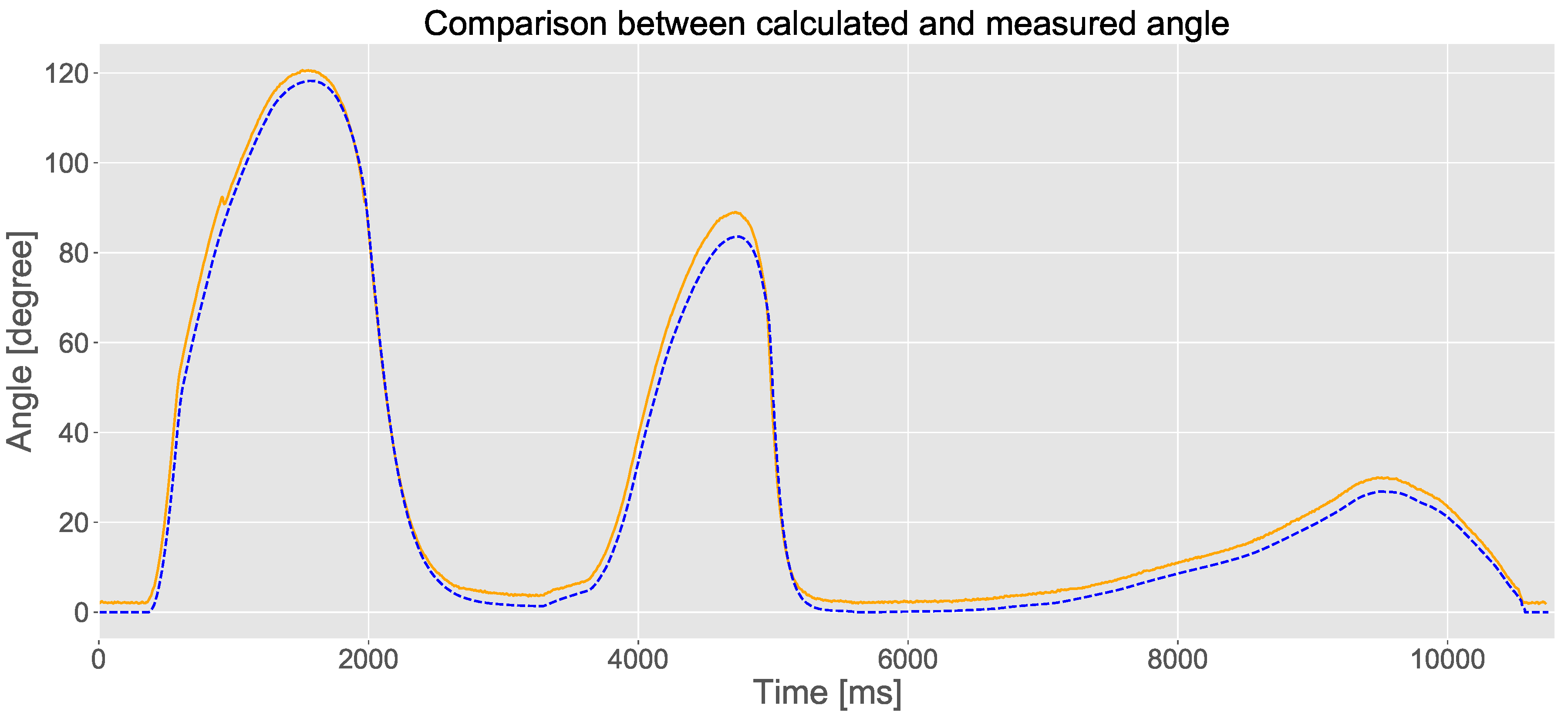
Figure 9 shows a graph illustrating the variation in the angle of the elbow joint during the execution of the experiment. The graph contains two curves: (i) the actual angle of the articulation of the user’s arm (value measured by the gyroscope), which is drawn with a solid orange line; and (ii) the output of the control system (the calculated value), which is drawn with a dashed blue line. It is possible to notice the similarity in the two trajectories presented in the figure; besides, the estimate declines slightly more sharply than the measured value.
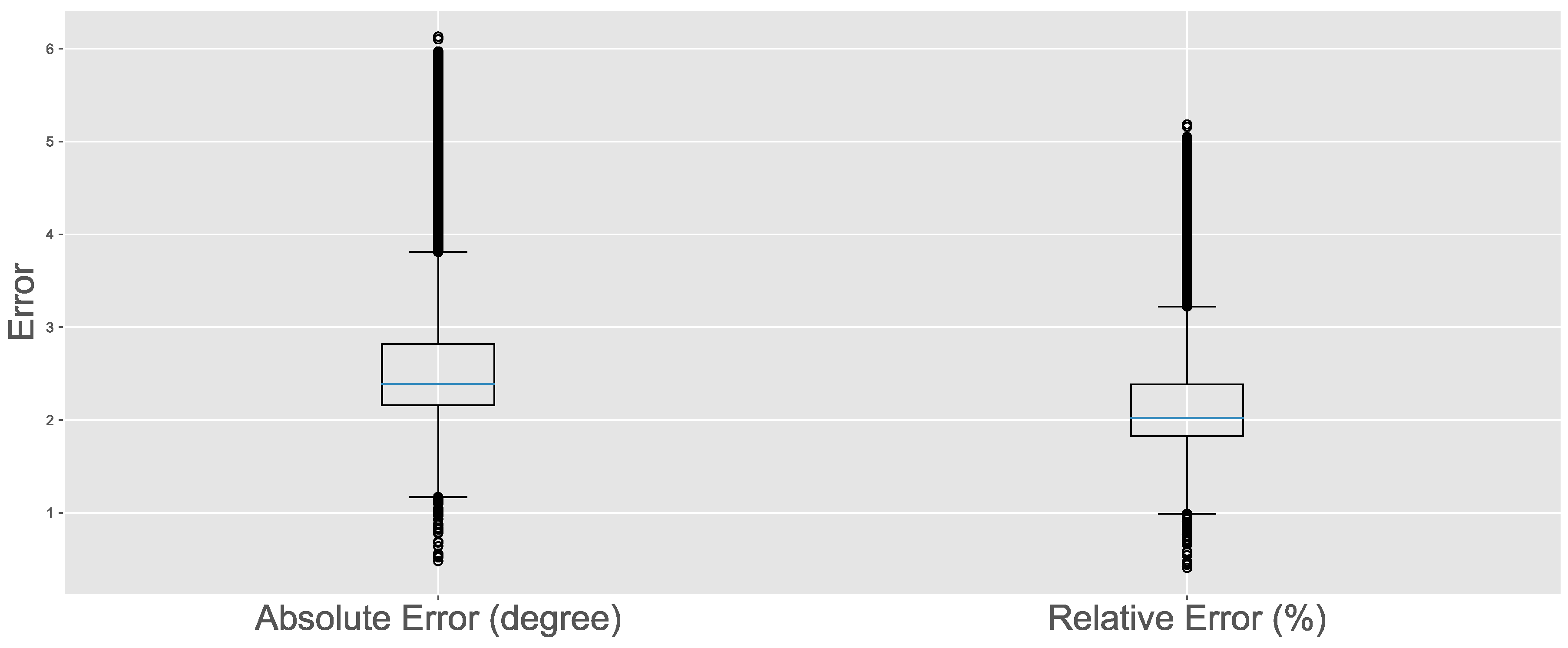
Another important feature is the consistency of performance in the three scenarios. The first contraction, which reaches 120 and is faster, has almost the same difference between the measured and estimated values as the last contraction, which reaches less than 40 and is slower. Figure 10 shows the variation of the system error throughout the test. The system generates a maximum error of less than 6% of the value measured by the gyroscopes. The average error equals 2.45%, with the first and third quadrants having a distance less than 1% from the average. This behavior affirms the stability of the solution.

5.2. Experiment 2: Two Degrees and no Load

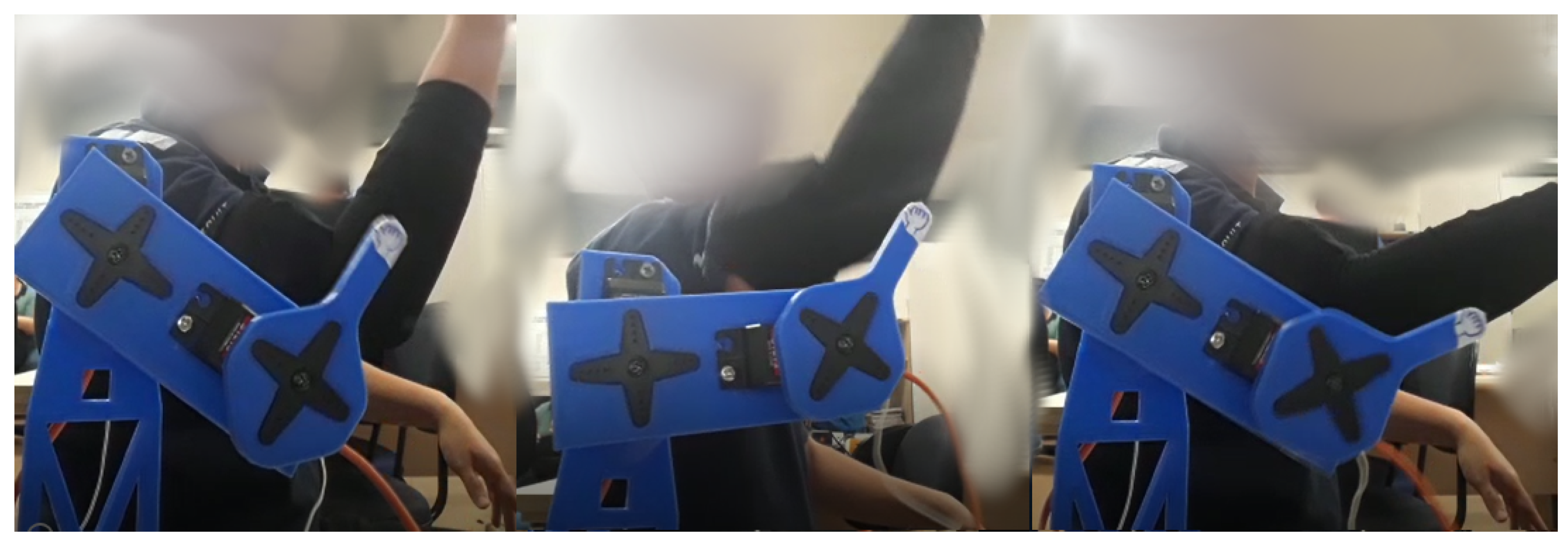
The second experiment comprised the execution of compound movements involving the activation of two muscles to assess the system’s accuracy. Figure 11 shows the control with two muscle groups. In compound movements, the user starts the movement with the arm completely relaxed and then contracts the biceps and the anterior deltoid until the elbow and shoulder meet at 90 . After the end of this movement, the user relaxes the muscles until the joints are approximately 45 .
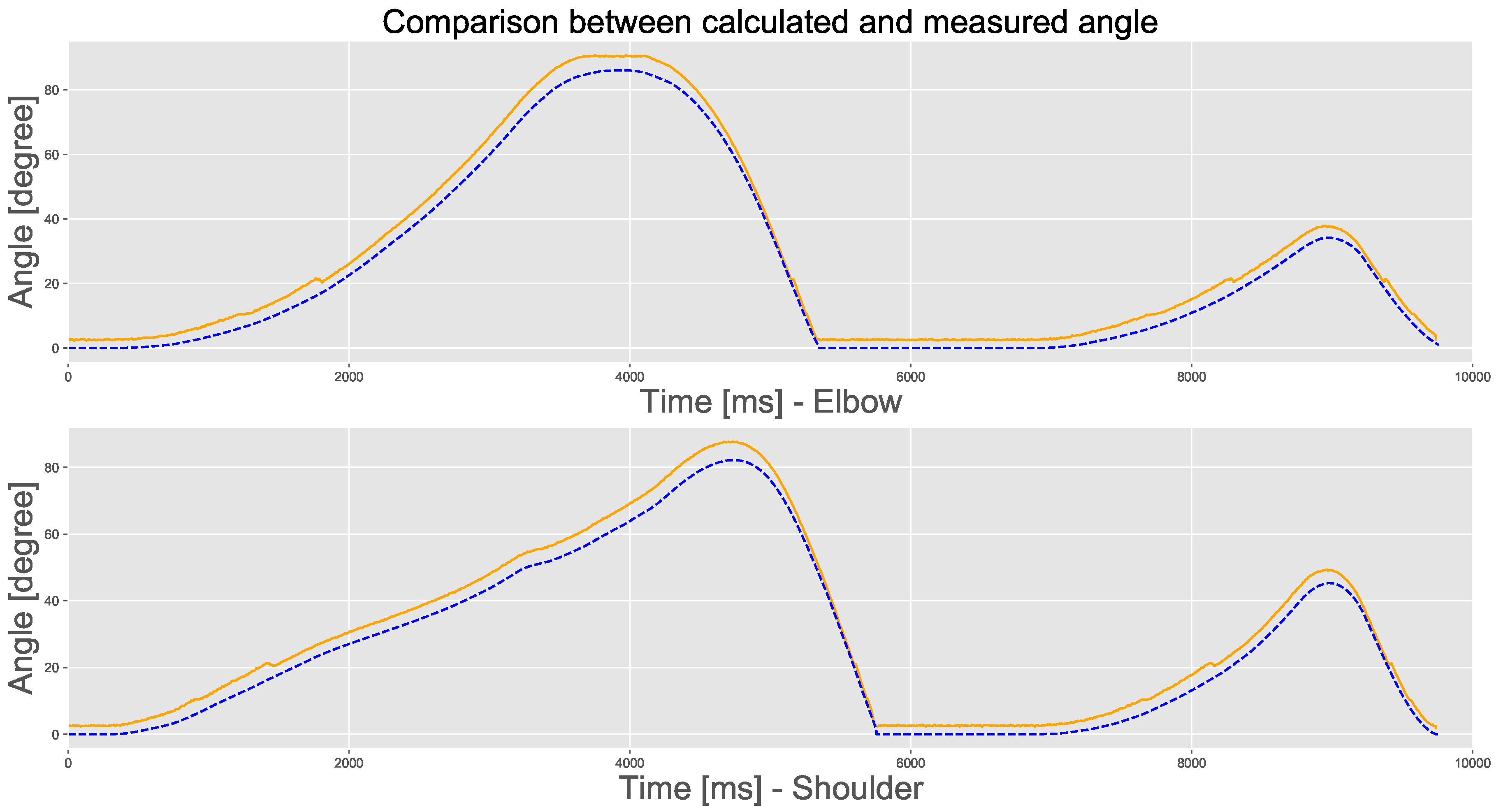
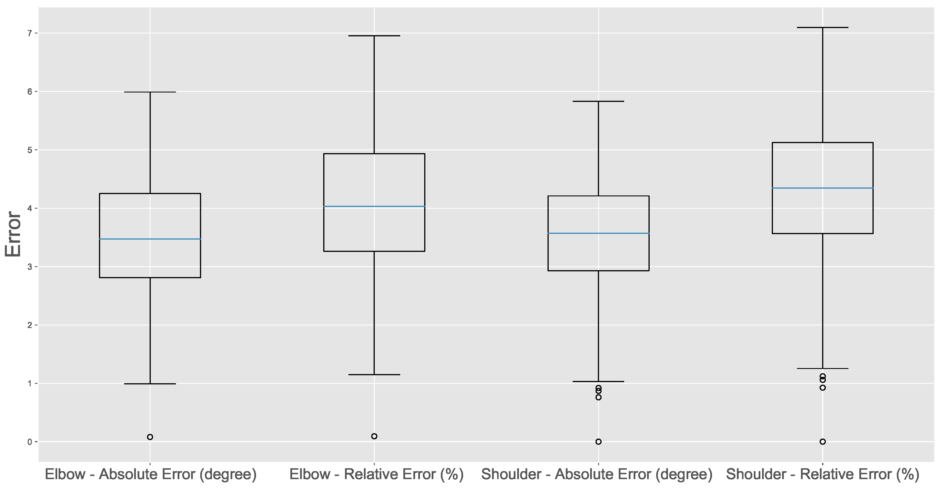
Figure 12 shows the estimated (dashed line) and measured (solid line) trajectories. We note that the system can follow small changes in trajectory made during the movement; this behavior is more accentuated in the shoulder trajectory. Figure 13, in turn, presents the system error. We can see that the system remains stable, despite having a slightly larger error than the previous test. This behavior comes from the sequential nature of the control system as the calculated value of the past joint is used to estimate the current joint.

5.3. Experiment 3: Two Degrees and Variable Load

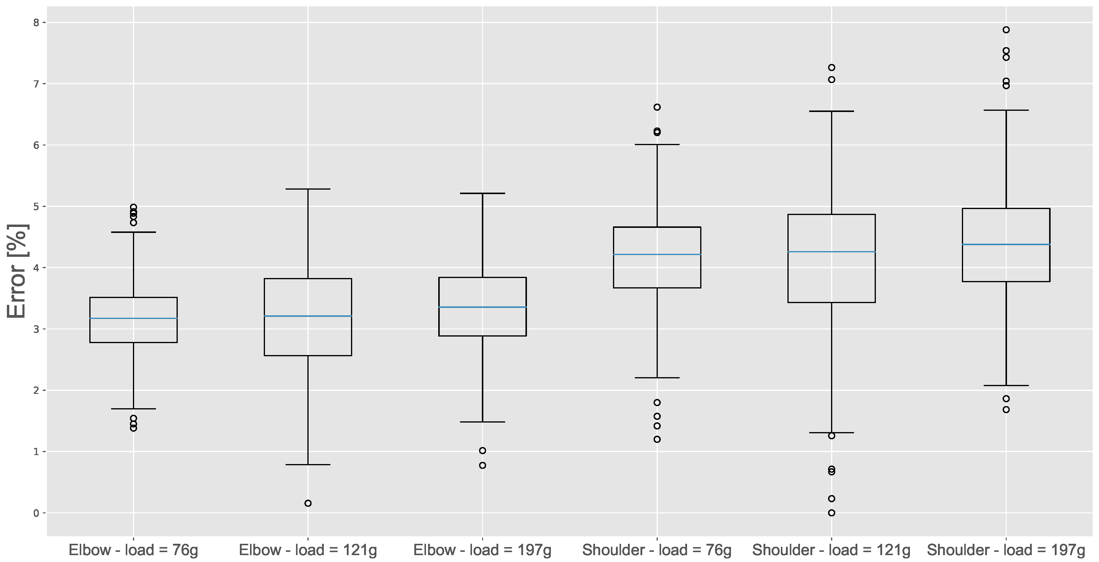
This third experiment assessed the system’s response in a scenario that includes three different loads: 76, 121, and 197 g. In the test, the user flexes the elbow and shoulder until both are approximately 45 . We increase the load at each execution to identify the error caused by the progression of the loads. Figure 14 shows how the system responds to the different loads applied. The shoulder and elbow errors varied little, and the average error variation was 0.294 for the shoulder and 0.355 for the elbow. The small variation shows that the impedance control is efficient in compensating the loads in the POC.

5.4. Discussion

Table 2 summarizes the results of three experiments and presents the root mean square error (RMSE) and the normalized RMSE (NRMSE) for each joint in each test. Considering only the scenarios with variable load, the average NRMSE equaled 3.24% for the elbow and 4.21% for the shoulder. Our solution has better precision than that obtained in related work presented in the literature. For instance, Lei [34] presented an average error of 8.42%, while the authors of [35] achieved an average error of 7.10% for the elbow. In [33], the average error equaled 10.82% for the elbow and 10.34% for the shoulder. Li et al. [32] only reported the maximum error (12%), which was higher than the maximum error we obtained in our work. These data are summarized in Table 3.

6. Conclusions

This paper presents a hybrid control system for the real-time operation of a robotic arm. The proposed system was validated and evaluated using a proof of concept with two degrees of freedom to mimic the movements of a human arm.
The experiments performed evaluated the system’s response to elbow and shoulder flexion and extension movements, with and without load. The average error of the elbow movement experiment, without load, was 2.452%. This average error increased in the experiment involving compound movements of the elbow and shoulder; however, it was less than 4.5%, even when a load was added. These results show that the proposed hybrid control model is valid, as it manages to mimic the movements of the upper limbs of a human in real-time. In addition, the evolution of methods such as this, of relative simplicity, aim to popularize the method and make its implementation cheaper, so that it can be used more widely.
As future work, we intend to investigate how to increase the system’s robustness by adding control variables for the user’s posture variations. We also intend to develop a more accurate model and investigate methods to reduce the computational cost and speed up the calibration of the coefficients.

Author Contributions

Conceptualization, L.D.L.d.S.; methodology, L.D.L.d.S. and T.F.P.; software, L.D.L.d.S.; validation, L.D.L.d.S.; writing—original draft preparation, L.D.L.d.S. and T.F.P.; and writing—review and editing, C.A.Z., L.O.S., and V.R.Q.L. All authors have read and agreed to the published version of the manuscript.

Funding

This research was funded in part by the Coordenação de Aperfeiçoamento de Pessoal de Nível Superior, Brasil (CAPES) (Finance Code 001), Conselho Nacional de Desenvolvimento Científico e Tecnológico (CNPq) (Processes 315287/2018-7 and 436982/2018-8), Fundanção de Amparo à Pesquisa do Estado de Santa Catarina (FAPESC) (Grant 2019TR169), and Fundação para a Ciência e a Tecnologia under Project UIDB/04111/2020.

Acknowledgments

The authors also like to acknowledge the collaboration of Computer Laboratory 7 of Instituto de Telecomunicações—IT Branch Covilhã—Portugal.

Conflicts of Interest

The authors declare no conflict of interest.

Abbreviations

The following abbreviations are used in this manuscript:
ADCAnalog-to-Digital
AIArtificial Intelligence
BPNNBack Propagation Neural Network
CMAContraction for Maximum Angle
CADComputer-aided Design
CVACerebrovascular Accident
CMRRCommon-mode Rejection Ratio
DACDigital-to-Analog Converter
EMGElectromyography
ESPEspressif
FSRForce Sensitive Resistor
LANLocal Area Network
MQTTMessage Queuing Telemetry Transport
MVCMaximum Voluntary Contraction
PCPersonal Computer
PLAPolylactic Acid
POCProof of Concept
RAMRandom Access Memory
RMSERoot Mean Square Error
sEMGSurface Electromyography

Symbols

The following symbols are used in this manuscript:
mMass read from the sensor
m d Mass of the system
b d Damping coefficient
k d Rigidity Of the system
xReal position
x r Reference position
f e External force
uInput control
k p Position constant
k v Speed constant
k c Correction constant
k e Electromyography constant
k g Gravitational constant
S a n Normalized antagonist signal
S a g Normalized agonist signal
θ a j Angle of anterior joint,
θ x 1 Previously calculated angle
θ p j Angle of the back joint
θ x Desired angle

References

  1. Kim, H.J.; Noh, J.; Yang, W. Knee-Assistive Robotic Exoskeleton (KARE-1) Using a Conditionally Singular Mechanism for Industrial Field Applications. Appl. Sci. 2020, 10, 5141. [Google Scholar] [CrossRef]
  2. Rzyman, G.; Szkopek, J.; Redlarski, G.; Palkowski, A. Upper Limb Bionic Orthoses: General Overview and Forecasting Changes. Appl. Sci. 2020, 10, 5323. [Google Scholar] [CrossRef]
  3. Young, A.J.; Ferris, D.P. State of the Art and Future Directions for Lower Limb Robotic Exoskeletons. IEEE Trans. Neural Syst. Rehabil. Eng. 2017, 25, 171–182. [Google Scholar] [CrossRef] [PubMed]
  4. Lenzi, T.; De Rossi, S.M.M.; Vitiello, N.; Carrozza, M.C. Intention-Based EMG Control for Powered Exoskeletons. IEEE Trans. Biomed. Eng. 2012, 59, 2180–2190. [Google Scholar] [CrossRef] [PubMed]
  5. Siu, H.C.; Arenas, A.M.; Sun, T.; Stirling, L.A. Implementation of a Surface Electromyography-Based Upper Extremity Exoskeleton Controller Using Learning from Demonstration. Sensors 2018, 18, 467. [Google Scholar] [CrossRef] [Green Version]
  6. Vitiello, N.; Lenzi, T.; Roccella, S.; De Rossi, S.M.M.; Cattin, E.; Giovacchini, F.; Vecchi, F.; Carrozza, M.C. NEUROExos: A Powered Elbow Exoskeleton for Physical Rehabilitation. IEEE Trans. Robot. 2013, 29, 220–235. [Google Scholar] [CrossRef]
  7. Zhang, T.; Tran, M.; Huang, H. Admittance Shaping-Based Assistive Control of SEA-Driven Robotic Hip Exoskeleton. IEEE/ASME Trans. Mech. 2019, 24, 1508–1519. [Google Scholar] [CrossRef]
  8. Kiguchi, K.; Hayashi, Y. An EMG-Based Control for an Upper-Limb Power-Assist Exoskeleton Robot. IEEE Trans. Syst. Man Cybern. Part B 2012, 42, 1064–1071. [Google Scholar] [CrossRef]
  9. Wang, D.; Meng, Q.; Meng, Q.; Li, X.; Yu, H. Design and Development of a Portable Exoskeleton for Hand Rehabilitation. IEEE Trans. Neural Syst. Rehabil. Eng. 2018, 26, 2376–2386. [Google Scholar] [CrossRef]
  10. Waris, A.; Kamavuako, E.N. Effect of threshold values on the combination of EMG time domain features: Surface versus intramuscular EMG. Biomed. Signal Process. Control 2018, 45, 267–273. [Google Scholar] [CrossRef] [Green Version]
  11. Li, Z.; Wang, B.; Sun, F.; Yang, C.; Xie, Q.; Zhang, W. sEMG-Based Joint Force Control for an Upper-Limb Power-Assist Exoskeleton Robot. IEEE J. Biomed. Health Inform. 2014, 18, 1043–1050. [Google Scholar] [CrossRef] [PubMed]
  12. Cram, J.; Criswell, E. Cram’s Introduction to Surface Electromyography; G-Reference, Information and Interdisciplinary Subjects Series; Jones & Bartlett Learning: Burlington, MA, USA, 2010. [Google Scholar]
  13. Merletti, R.; Parker, P. Electromyography: Physiology, Engineering, and Non-Invasive Applications; IEEE Press Series on Biomedical Engineering; Wiley: Hoboken, NJ, USA, 2004. [Google Scholar]
  14. Nordin, M.; Frankel, V.H. Basic Biomechanics of the Musculoskeletal System, 4th North American ed.; LWW: Philadelphia, PA, USA, 2012. [Google Scholar]
  15. Kiguchi, K.; Rahman, M.H.; Sasaki, M.; Teramoto, K. Development of a 3DOF mobile exoskeleton robot for human upper-limb motion assist. Robot. Auton. Syst. 2008, 56, 678–691. [Google Scholar] [CrossRef]
  16. Tang, Z.; Yu, H.; Cang, S. Impact of Load Variation on Joint Angle Estimation From Surface EMG Signals. IEEE Trans. Neural Syst. Rehabil. Eng. 2016, 24, 1342–1350. [Google Scholar] [CrossRef] [PubMed]
  17. Guidotti, D.; Leofante, F.; Tacchella, A.; Castellini, C. Improving Reliability of Myocontrol Using Formal Verification. IEEE Trans. Neural Syst. Rehabil. Eng. 2019, 27, 564–571. [Google Scholar] [CrossRef] [PubMed]
  18. Ueda, J.; Ming, D.; Krishnamoorthy, V.; Shinohara, M.; Ogasawara, T. Individual Muscle Control Using an Exoskeleton Robot for Muscle Function Testing. IEEE Trans. Neural Syst. Rehabil. Eng. 2010, 18, 339–350. [Google Scholar] [CrossRef]
  19. Lu, L.; Wu, Q.; Chen, X.; Shao, Z.; Chen, B.; Wu, H. Development of a sEMG-based torque estimation control strategy for a soft elbow exoskeleton. Robot. Auton. Syst. 2019, 111, 88–98. [Google Scholar] [CrossRef]
  20. Chowdhury, R.; Reaz, M.B.I.; Mohd Ali, M.; A Bakar, A.A.; Chellappan, K.; Chang, T.G. Surface Electromyography Signal Processing and Classification Techniques. Sensors 2013, 13, 12431–12466. [Google Scholar] [CrossRef]
  21. Betthauser, J.L.; Hunt, C.L.; Osborn, L.E.; Masters, M.R.; Lévay, G.; Kaliki, R.R.; Thakor, N.V. Limb Position Tolerant Pattern Recognition for Myoelectric Prosthesis Control with Adaptive Sparse Representations From Extreme Learning. IEEE Trans. Biomed. Eng. 2018, 65, 770–778. [Google Scholar] [CrossRef]
  22. Al-Shuka, H.; Leonhardt, S.; Zhu, W.H.; Song, R.; Ding, C.; Li, Y. Active Impedance Control of Bioinspired Motion Robotic Manipulators: An Overview. Appl. Bionics Biomech. 2018. [Google Scholar] [CrossRef]
  23. Zhuang, Y.; Yao, S.; Ma, C.; Song, R. Admittance Control Based on EMG-Driven Musculoskeletal Model Improves the Human–Robot Synchronization. IEEE Trans. Ind. Inform. 2019, 15, 1211–1218. [Google Scholar] [CrossRef]
  24. Cafolla, D.; Wang, M.; Carbone, G.; Ceccarelli, M. LARMbot: A New Humanoid Robot with Parallel Mechanisms. CISM Int. Centre Mech. Sci. Courses Lectures 2016, 569, 275–283. [Google Scholar] [CrossRef]
  25. Cafolla, D.; Russo, M.; Carbone, G. CUBE, a Cable-driven Device for Limb Rehabilitation. J. Bionic Eng. 2019, 16, 492–502. [Google Scholar] [CrossRef]
  26. Hall, S. Basic Biomechanics; McGraw-Hill: New York, NY, USA, 2007. [Google Scholar]
  27. Barbero, M.; Merletti, R.; Rainoldi, A. Atlas of Muscle Innervation Zones: Understanding Surface Electromyography and Its Applications; Springer: Milan, Italy, 2012. [Google Scholar] [CrossRef]
  28. De Luca, C.J. The use of surface electromyography in biomechanics. J. Appl. Biomech. 1997, 13, 135–163. [Google Scholar] [CrossRef] [Green Version]
  29. Zeng, Y.; Yang, J.; Yin, Y. Gaussian Process-Integrated State Space Model for Continuous Joint Angle Prediction from EMG and Interactive Force in a Human-Exoskeleton System. Appl. Sci. 2019, 9, 1711. [Google Scholar] [CrossRef] [Green Version]
  30. Dietrich, A.M. Whole-Body Impedance Control of Wheeled Humanoid Robots. Ph.D. Thesis, Technische Universität München, Munich, Germany, 2015. [Google Scholar]
  31. Liang, C.; Hsiao, T. Admittance Control of Powered Exoskeletons Based on Joint Torque Estimation. IEEE Access 2020, 8, 94404–94414. [Google Scholar] [CrossRef]
  32. Li, Z.; Huang, Z.; He, W.; Su, C. Adaptive Impedance Control for an Upper Limb Robotic Exoskeleton Using Biological Signals. IEEE Trans. Ind. Electron. 2017, 64, 1664–1674. [Google Scholar] [CrossRef]
  33. Liu, J.; Ren, Y.; Xu, D.; Kang, S.H.; Zhang, L. EMG-Based Real-Time Linear-Nonlinear Cascade Regression Decoding of Shoulder, Elbow, and Wrist Movements in Able-Bodied Persons and Stroke Survivors. IEEE Trans. Biomed. Eng. 2020, 67, 1272–1281. [Google Scholar] [CrossRef]
  34. Lei, Z. An upper limb movement estimation from electromyography by using BP neural network. Biomed. Signal Process. Control 2019, 49, 434–439. [Google Scholar] [CrossRef]
  35. Weixing, W.; Qianqian, L.; Chao, L.; Shouqian, S. Effects of Proprioception and Visual Focus of Attention on Surface Electromyography Proportional Control. Appl. Sci. 2019, 9, 730. [Google Scholar] [CrossRef] [Green Version]
  36. Advancer Technologies. Sensor for Microcontroller Applications. Available online: https://github.com/AdvancerTechnologies/MyoWare_MuscleSensor/blob/master/Documents/AT-04-001.pdf (accessed on 27 August 2020).
  37. Interlink electronics. FSR 402 Data Sheet. Available online: https://www.interlinkelectronics.com/request-data-sheets (accessed on 27 August 2020).
  38. Inven Sense. MPU-6000 and MPU-6050 Product Specification Revision 3.4. Available online: https://invensense.tdk.com/wp-content/uploads/2015/02/MPU-6000-Datasheet1.pdf (accessed on 27 August 2020).
  39. ServoDataBase. Batan S1213 Servo. Available online: https://servodatabase.com/servo/batan/s1213 (accessed on 27 August 2020).
  40. Espressif Systems. ESP32 Series datasheet. Available online: https://www.espressif.com/sites/default/files/documentation/esp32_datasheet_en.pdf (accessed on 27 August 2020).
  41. Raspberry Pi Foundation. Datasheet Raspberry Pi Compute Module 3+. Available online: https://www.raspberrypi.org/documentation/hardware/computemodule/datasheets/rpi_DATA_CM3plus_1p0.pdf (accessed on 27 August 2020).
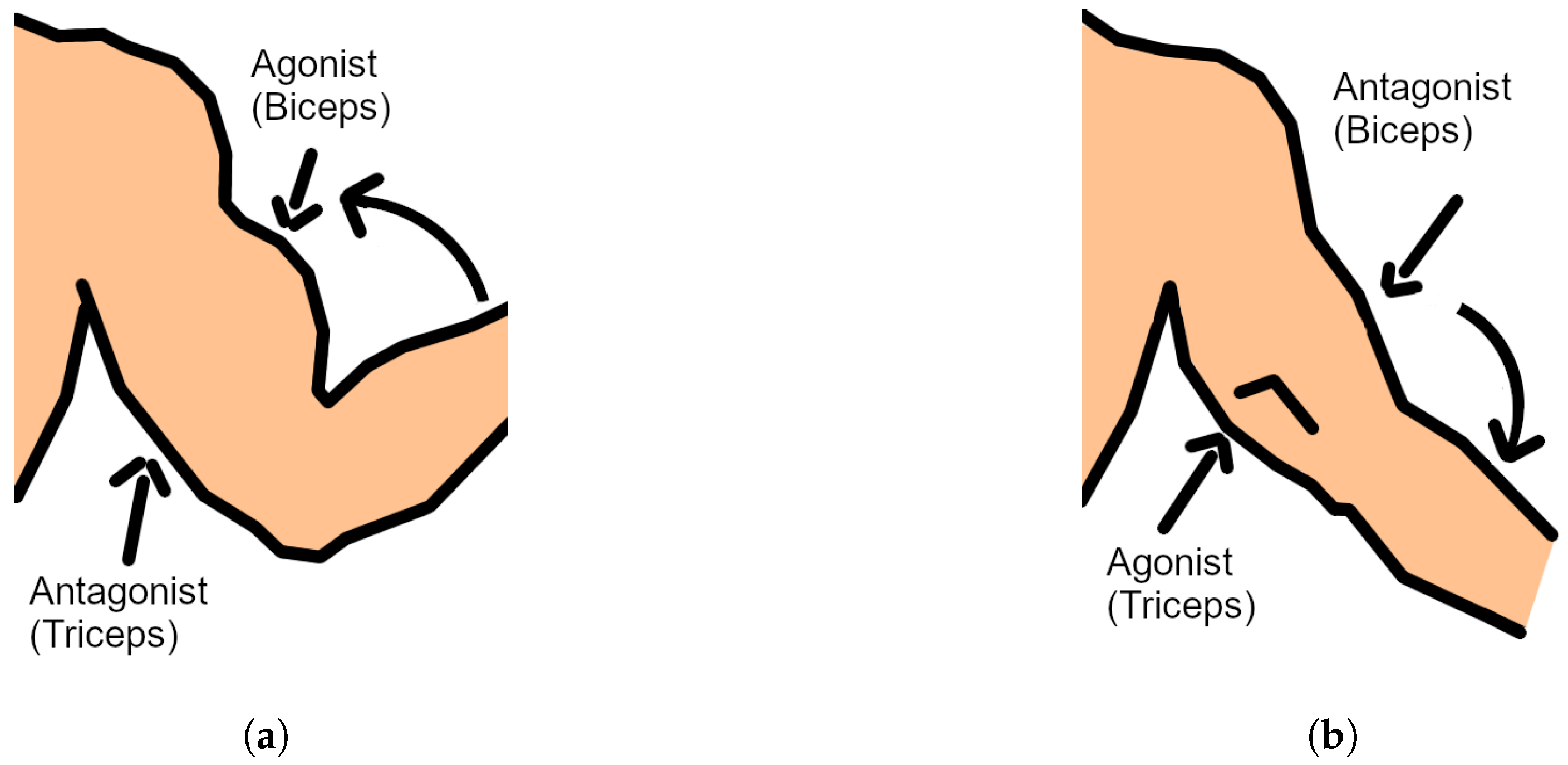
Figure 1. Agonist and antagonist muscles of the elbow movements: (a) flexion; and (b) extension.
Applsci 10 07146 g001
Figure 2. Hybrid control system.
Applsci 10 07146 g002
Figure 3. System Architecture.
Applsci 10 07146 g003
Figure 4. Design of the wearable suit to contain the electromyographic sensors and gyroscopes.
Applsci 10 07146 g004
Figure 5. Test of the EMG sensor.
Applsci 10 07146 g005
Figure 6. Software interface developed for real-time signal analysis.
Applsci 10 07146 g006
Figure 7. The proof of concept: (a) 3D modeling; and (b) physical implementation.
Applsci 10 07146 g007
Figure 8. Movements made in the elbow test: (a) flexion; and (b) extension.
Applsci 10 07146 g008
Figure 9. Graph of the trajectory of the elbow joint test. The solid blue line is the values read by the gyroscope, and the dashed orange line is the value computed by the control system.
Applsci 10 07146 g009
Figure 10. Analysis of absolute and normalized errors in the control of a degree of freedom.
Applsci 10 07146 g010
Figure 11. The POC of the robotic arm (in the foreground) mimics the user’s arm. The user (in the background) is wearing the suit with the EMG sensors.
Applsci 10 07146 g011
Figure 12. Graph of the trajectory of the elbow and shoulder joint test. The solid blue line is the values read by the gyroscope, and the dashed orange line is the value computed by the control.
Applsci 10 07146 g012
Figure 13. Analysis of the absolute and normalized error of the control of two degrees of freedom.
Applsci 10 07146 g013
Figure 14. Analysis of the normalized error with two degrees of freedom in tests with different loads.
Applsci 10 07146 g014
Table 1. Related work.
Feature[32][33][34][35]This Work
Control
technique
Shiftness-based
impedance
Linear regression
trained with EMG
and limb position
BPNN trained
wth EMG and
limb position
BPNN trained
with EMG and
limb position
Impedance and
admittance
control
Body limbArmArmArmArmArm
Tested jointsElbow and
shoulder
Elbow, shoulder
and wristle
ElbowElbowElbow and
shoulder
Embedded
implementation
NoNoPartialNoYes
Table 2. Error obtained in the three experiments.
TestRMSE ElbowRMSE ShoulderNRMSE ElbowNRMSE Shoulder
One degree—no load2.735 -2.452%-
Two degrees—no load3.609 3.642 4.190%4.433%
Two degrees—load = 76 g2.531 3.339 3.164%4.174%
Two degrees—load = 121 g2.431 3.109 3.198%4.091%
Two degrees—load = 197 g2.658 3.464 3.365%4.385%
Table 3. Comparison with related works.
Test[32][33][34][35]This Work
One degreeNRMSE = 8.42%
Max. = 30%
NRMSE = 7.10%NRMSE = 2.45%
Max. = 5.18%
Two degrees
(Elbow)
Max. = 12%NRMSE = 10.82%NRMSE = 4.19%
Max. = 6.96%
Two degrees
(Shoulder)
Max. = 12%NRMSE = 10.34%NRMSE = 4.19%
Max. = 7.10%
Publisher’s Note: MDPI stays neutral with regard to jurisdictional claims in published maps and institutional affiliations.