Article

Experimental Study on Seismic Retrofitting of Reinforced Concrete Frames Using Welded Concrete-Filled Steel Tubes

Department of Architectural Engineering, Kyung Hee University, Deogyeong-Daero 1732, Yongin 17104, Korea
*
Author to whom correspondence should be addressed.
Appl. Sci. 2020, 10(20), 7061; https://doi.org/10.3390/app10207061
Submission received: 16 September 2020 / Revised: 1 October 2020 / Accepted: 6 October 2020 / Published: 12 October 2020
(This article belongs to the Section Civil Engineering)

Abstract

:
Buildings constructed with non-seismic details are at risk of damage and collapse when an earthquake occurs due to a lack of strength, stiffness, and ductility. For reinforced concrete (RC) moment-resisting frames, seismic retrofitting methods that can enhance strength or ductility should be applied. However, such strategies have many disadvantages related to constructability, serviceability, securing integrity, and cost. In this paper, a welded concrete-filled steel tube (WCFST) system was examined in order to resolve the problems of the existing seismic retrofitting methods for RC moment-resisting frames. To evaluate the seismic performance of the proposed system, two specimens, one with non-seismic details and another reinforced with a WCFST seismic system, were manufactured for the cyclic loading tests. As a result of the experiments, the specimen retrofitted with the WCFST system showed maximum load, effective stiffness, and energy dissipation capacity values approximately 3, 2, and 2.5 times greater, respectively, than those obtained from the existing reinforced concrete frame specimen. The experimental results indicate that the proposed WCFST system is expected to be effective at improving the seismic performance by enhancing both the strength of the existing reinforced concrete frame structures and the dissipation of the seismic energy.

1. Introduction

In the construction of concrete buildings without seismic details, the seismic load is not taken into account. In particular, concrete moment frames without seismic details pose serious risks for structural damage and collapse due to a lack of strength, stiffness, and ductility. To prevent damage caused by earthquakes, the techniques for the seismic rehabilitation of existing buildings by the federal emergency management agency (FEMA 547) [1] presented guidelines to improve the seismic performance. Ensuring sufficient strength and ductility in concrete moment frames is emphasized in FEMA 547. FEMA 547 [1] also proposes methods such as adding new structural elements (e.g., a concrete or masonry shear wall and steel braced frame) and increasing the cross-sectional size of the columns or beams in order to improve the seismic performance of concrete moment frames. However, the method of adding new elements can lead to the space inefficiency or retrofitting costs becoming uneconomical [2]. Furthermore, if the newly added elements and existing members do not behave in an identical manner, the structure may not resist an increasing seismic load, and brittle fractures may occur [3]. The method of increasing the cross-sectional size has disadvantages, such as reducing the space of a building and requiring foundation reinforcement as a result of an increase in the building weight. Therefore, a number of studies have been conducted on seismic retrofitting methods that can mitigate the disadvantages of the existing seismic retrofitting approaches. The research has focused on seismic retrofitting methods using fiber-reinforced polymer (FRP) [2,4,5,6,7,8], steel beams [3,9], and dampers [10,11,12,13,14]. Although new seismic retrofitting methods have been studied to improve the existing retrofitting methods, there are some drawbacks; the drawbacks of the seismic retrofitting method using FRP are the relatively high cost of epoxies, inability to attach on wet surfaces, difficulty conducting post-earthquake assessment of the damage suffered by the reinforced concrete that is behind the undamaged FRP jackets, and so on [4]. There are some disadvantages with the seismic reinforcement method of absorbing the seismic energy using dampers, namely, aesthetic problems, maintenance difficulties, and highly nonlinear behavior [10]. In particular, in the case of retrofitting with FRP, steel beams, and dampers, because of the characteristics of these methods, construction is only possible when the members requiring retrofitting are exposed to the outside. Therefore, if a member requiring retrofitting is not exposed to the outside, an additional demolition process is required, which may increase the construction period and cost.
This paper proposes a seismic retrofitting method using welded concrete-filled steel tubes (WCFSTs) that improve both the strength and energy dissipation. The WCFST system functions by attaching the CFST frame to only the part of the structural member exposed to the outside environment. A base plate is installed to the existing reinforced concrete frame, and integration is ensured by welding the CFST frame to the base plate. This technique has an advantage in that it is possible to utilize the space during construction and it is easy to check the status of the existing members after an earthquake. To evaluate the performance of the WCFST seismic-resistant system, both a non-seismically designed reinforced concrete frame specimen and a specimen retrofitted with the WCFST system were subjected to cyclic lateral loading tests.

2. Seismic Retrofitting Method Using Welded Concrete-Filled Steel Tubes

Concrete-filled steel tubes (CFSTs) are structural members consisting of circular or square steel tubes charged with concrete (the concrete is confined to the interior of the tubes). Such members exhibit suitable stiffness, resistance, and deformation characteristics. Since the 2000s, several studies have been conducted on the seismic performance of CFSTs and their corresponding structural performance. The results of such research have confirmed the effectiveness of CFSTs in improving seismic performance [15,16]. However, studies focused on utilizing CFST structures in the seismic retrofitting of existing buildings that are not seismic-resistant have been limited. As shown in Figure 1, the WCFST system proposed in this paper can reduce lateral deformation and increase seismic resistance via the attachment of concrete-filled steel tubes to the surface of an existing frame structure consisting of beams and columns. The seismic retrofitting procedure using the WCFST system is displayed in Figure 2. Firstly, the finishing material on the retrofitting surface is removed and a base plate is installed, as shown in Figure 2a. The base plate is then fixed using chemical anchors and reinforcement is placed, as illustrated in Figure 2b. After fixing the base plate to the existing frame, the CFST frame is installed on the columns and then the beams, as shown in Figure 2c; the base plate and CFST frame are connected by welding. High strength mortar is subsequently charged inside of the steel tubes. The WCFST system does not require additional formwork and is not affected by internal spatial conditions, as it is a method of construction on the outside of the structure. In addition, the strategy is advantageous in that it can minimize both damage to the structural members and changes in elevation by eliminating the need to remove existing structural members.

3. Experimental Program

3.1. Specimen Details

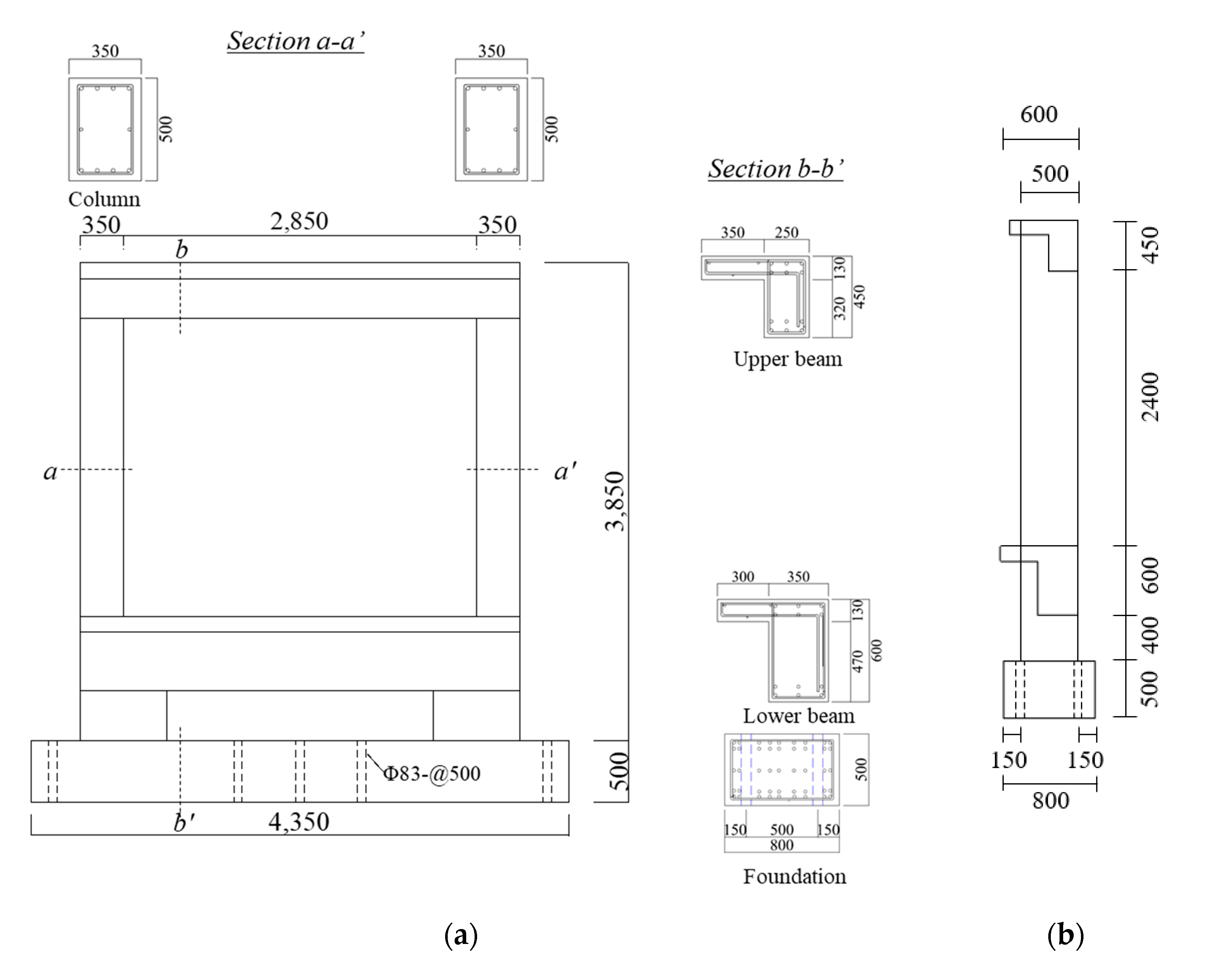
To evaluate the effects of seismic retrofitting with the WCFST system, one test specimen consisting of a reinforced concrete (RC) moment-resisting frame without seismic details, named the non-seismic reinforced control specimen (NRC), and one frame specimen with the WCFST system, named WCFST, were fabricated. The test specimens were frame structures consisting of a column, upper beam, lower beam, and foundation; the dimensions and reinforcement details of these elements are summarized in Table 1. Details regarding the reinforced concrete frame and CFST frame attached to the WCFST specimen are provided in Figure 3 and Figure 4, respectively. The 28-day compressive strength of the concrete used for the specimens was 21 MPa, while the yield strength of the deformed reinforcement was 400 MPa. Steel with a yield strength of 275 MPa was employed for the CFST frame attached to the WCFST test specimen, and mortar with a compressive strength of 24 MPa was utilized to fill the inside of the steel tubes. The process of constructing the WCFST system on the reinforced concrete frame is shown in Figure 5. After drilling to fix the base plate on the outside of the column, a chemical anchor was constructed to unify the base plate and test specimen. The reinforcement was then arranged on the base plate, followed by welding of the steel tube and base plate to install the CFST frame. Lastly, high-strength mortar was injected inside the CFST frame and the surface was ultimately finished.

3.2. Test Setup

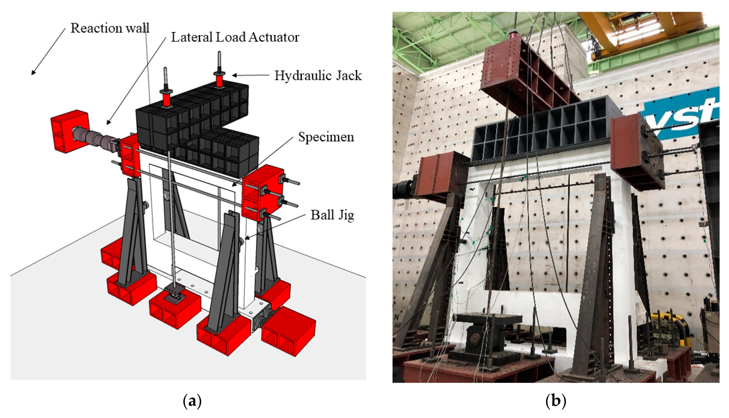
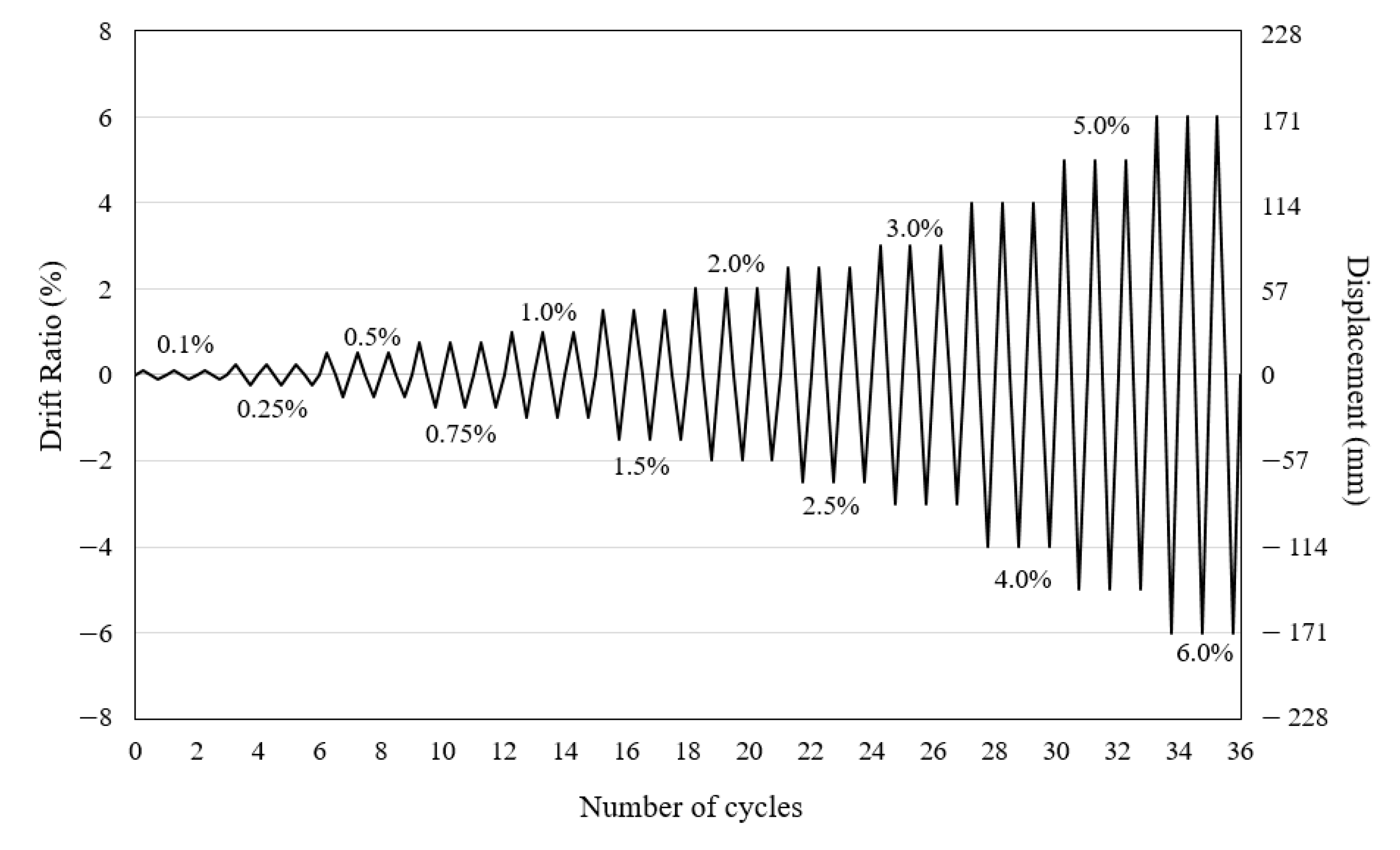
The cyclic lateral loading test setup is presented in Figure 6. Here, cyclic lateral loading was applied to the top of the column using a hydraulic actuator with a maximum load of 200 tons; the actuator was installed between the bearing wall and test specimen. To pull test specimens in a negative direction, a steel rod and jig were attached to the specimen face corresponding to the direction of the force. Ball jigs were installed in the center of the column to prevent torsion of the test specimens by lateral force. To account for the load conditions of the actual structure, a 50-ton axial force was introduced on both columns using hydraulic jacks with a maximum load of 100 tons. As shown in Figure 7, the load protocol was set to be cycled three times for each drift ratio, followed by an incremental increase to approximately 171 mm; this corresponds to a maximum drift ratio of 6%. Steel strain gauges were attached to lateral and transverse reinforcements placed at the end of the column and beam in order to verify deformation of the reinforcement steel upon the application of lateral loads to the test specimens. Concrete strain gauges were attached to the end of the column where the greatest stress was expected to be concentrated. In the case of the WCFST test specimen, the strain gauge was attached to the CFST frame applied to the end of the beam and column to measure the deformation of the CFST structure.

4. Experimental Results and Analysis

4.1. Cracks and Failure Modes of Specimens

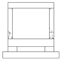
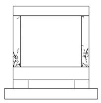
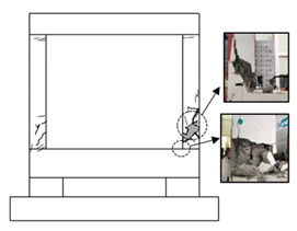
The crack patterns and failure of each specimen according to an increase in the drift ratio are shown in Table 2. For the NRC specimen, which represents an RC moment-resisting frame without seismic details, initial cracks occurred at the top, bottom of the column, and beam-column joints at a drift ratio of 1%. Shear cracks were also present at the bottom of the column when the drift ratio reached 1.5%, at which point the concrete began to spall. As the load increased and the drift ratio reached 2%, the width of the shear cracks at the bottom of the column increased significantly. In the first cycle, at a drift ratio of 2.5%, severe spalling of the concrete occurred at the bottom left of the column. The experiment was ultimately terminated because of failure at the bottom of the column and bending of the lateral reinforcement. For the WCFST test specimen, the behavior was similar to that observed for the NRC specimen without seismic details, which showed up to a 1.5% drift ratio. Shear cracks were observed on the column as the drift ratio reached 2%; the shear cracks formed at the bottom of the column and expanded to the top of the column after repeated cycles. Unlike the control specimen, the width of the shear cracks did not increase significantly and there was no spalling of the concrete. As the drift ratio reached 2.5%, the width of the cracks at the bottom of the column increased, and concrete spalling was observed at the bottom right of the column. Upon repeated cycling, the width of the shear cracks at the bottom left of the column increased and the experiment was terminated. No deformation or detachment of the CFST frames occurred, and no spalling of the concrete was evident in the CFST frame-column joints.

4.2. Load–Displacement Relationships and Strains

The hysteretic behavior of each specimen under cyclic loading, along with the envelope curves for all test specimens, are presented in Figure 8 and Figure 9, respectively. The maximum load of the NRC specimen was 322 kN in the positive direction and 314.2 kN in the negative direction when the drift ratio was 2%. As the load increased, shear cracks developed at the bottom of the column and spalling of the concrete occurred. The maximum load subsequently decreased to 311.4 kN (94% of the maximum load) during the first cycle at a 2.5% drift ratio, and the experiment was terminated as a result of shear failure at the bottom left of the column. In the case of the WCFST specimen, the load reached a maximum during the first cycle at a 2.5% drift ratio; the load was 1013.3 kN in the positive direction and 940.5 kN in the negative direction, about 3.15 times higher than that observed for the NRC specimen. The test results are summarized in Table 3. When the drift ratio was 0.1%, the load capacity of the WCFST specimen attached to the CFST frame was approximately 1.9 times that of the NRC specimen attached to a non-seismically designed frame. This disparity in load capacity became greater as the drift ratio increased, and the load capacity of the WCFST specimen was 2.8 times that of the NRC test specimen, at a drift ratio of 1.5%; it was at this point that shear cracks occurred in the columns of both specimens. These observations indicate that for the same lateral displacement, the load was greater for the specimen reinforced by the WCFST system, thereby confirming that the seismic retrofitting method using the CFST frame effectively enhances the strength of existing reinforced concrete frame structures.
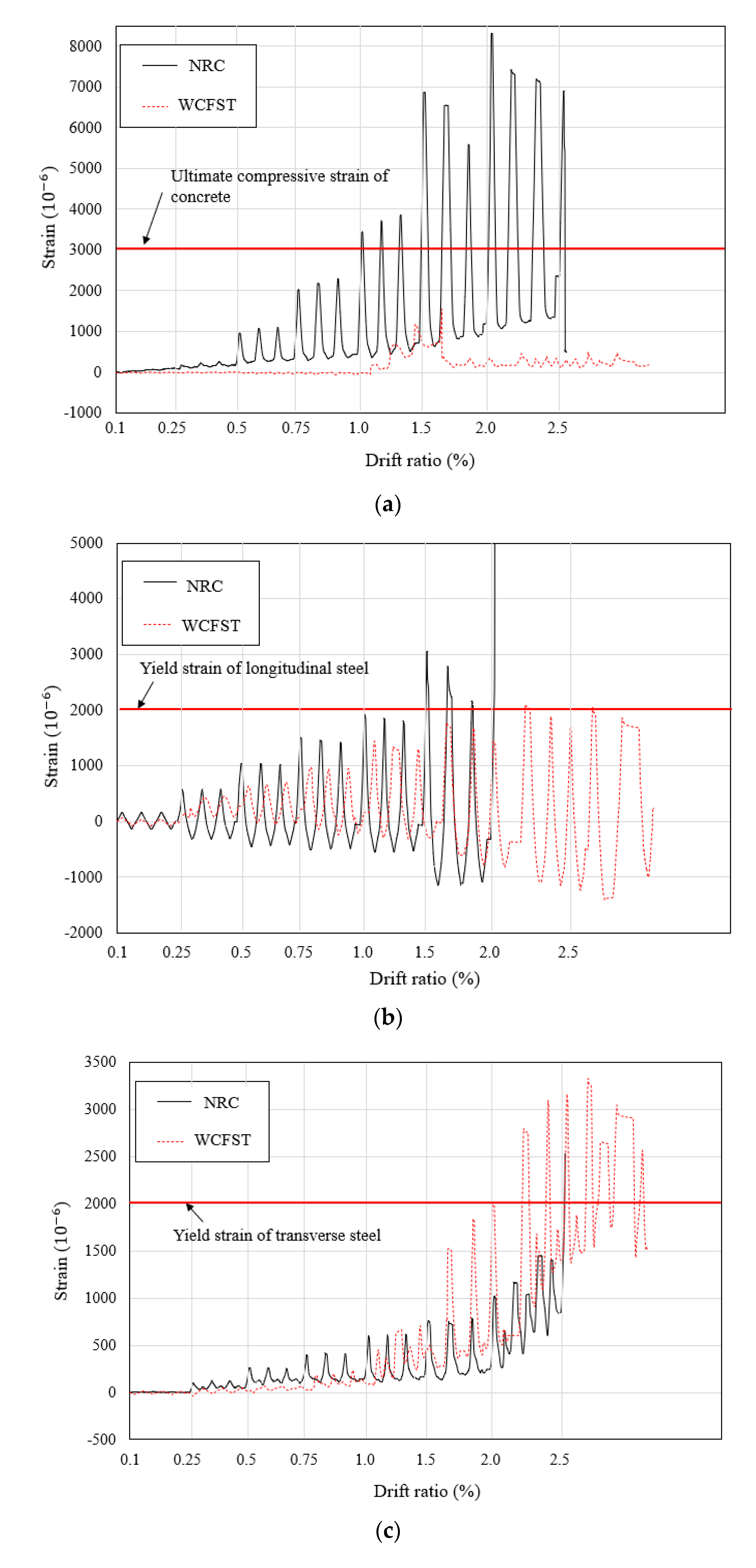
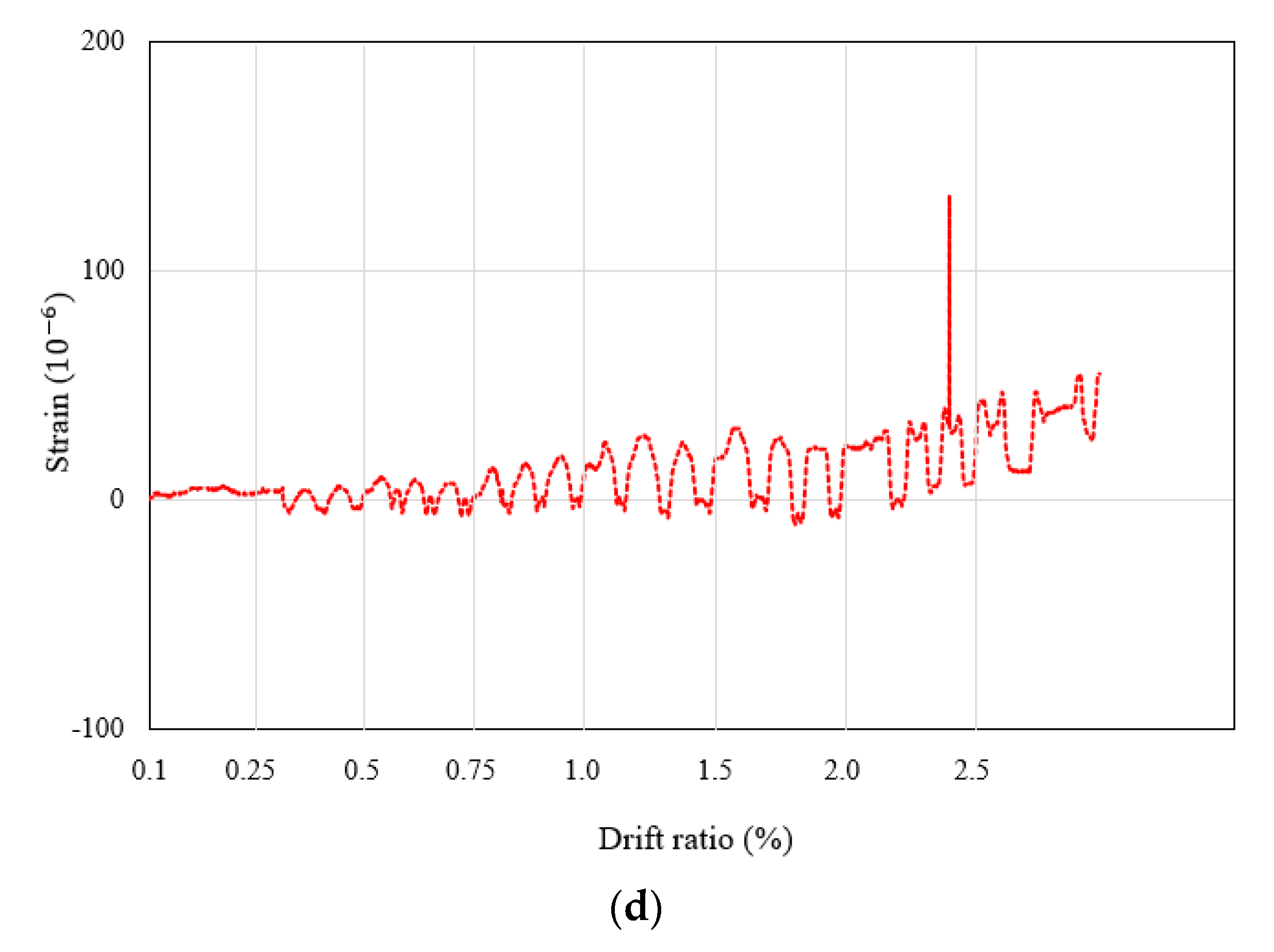
The strain values measured in the beams and columns of each test specimen during the cyclic loading test are shown in Figure 10 and Figure 11, respectively. The strain values measured for the main rebars and stirrups at the end of the beams in the NRC and WCFST specimens were similar up to a drift ratio of 0.75%. However, from a 0.75% drift ratio until failure, the strain of the WCFST specimen was more than twice that of the NRC specimen. It was confirmed that the strain on the main rebars and stirrups increased because of the increased stress in the main rebars and stirrups, as the maximum load of the WCFST specimen was approximately three times that of the NRC specimen. The CFST attached to beams of the WCFST specimen did not yield at a drift ratio of 2.5% (where the experiment was terminated), nor did the strain increase significantly. As shown in Figure 11, the strain of the concrete at the end of the column in the NRC specimen exceeded 0.003, the ultimate compressive strain of concrete, after a drift ratio of 1% was reached. For the longitudinal and transverse reinforcement of the column, the strain for all specimens reached 0.0002, the yield strain of steel, at drift ratios of 1.5% and 2%, respectively. While the strain increased gradually after the yield of rebars in the WCFST specimens, the strain values for the longitudinal and transverse reinforcement in the NRC specimens increased rapidly during the third cycle with a 2% drift ratio. This indicates a significant development in the deformation of the longitudinal and transverse reinforcement as the concrete exceeded the ultimate compressive strain and the rebar yielded. In the NRC specimen, spalling in the concrete was observed at the bottom of the column and the cracks progressed rapidly, as shown in Table 2. The strain of the CFST at the end of the column showed a strain value less than 10% of the 0.001375 yield strain and, thus, there was little deformation of the CFST. In addition, it was determined that no deformation of the CFST occurred upon failure of the test specimen because the yield strain of the CFST was not reached at a 2.5% drift ratio (when the test was terminated). According to Table 2, it can be confirmed that the deformation of the CFST frame did not occur.

4.3. Effective Stiffness

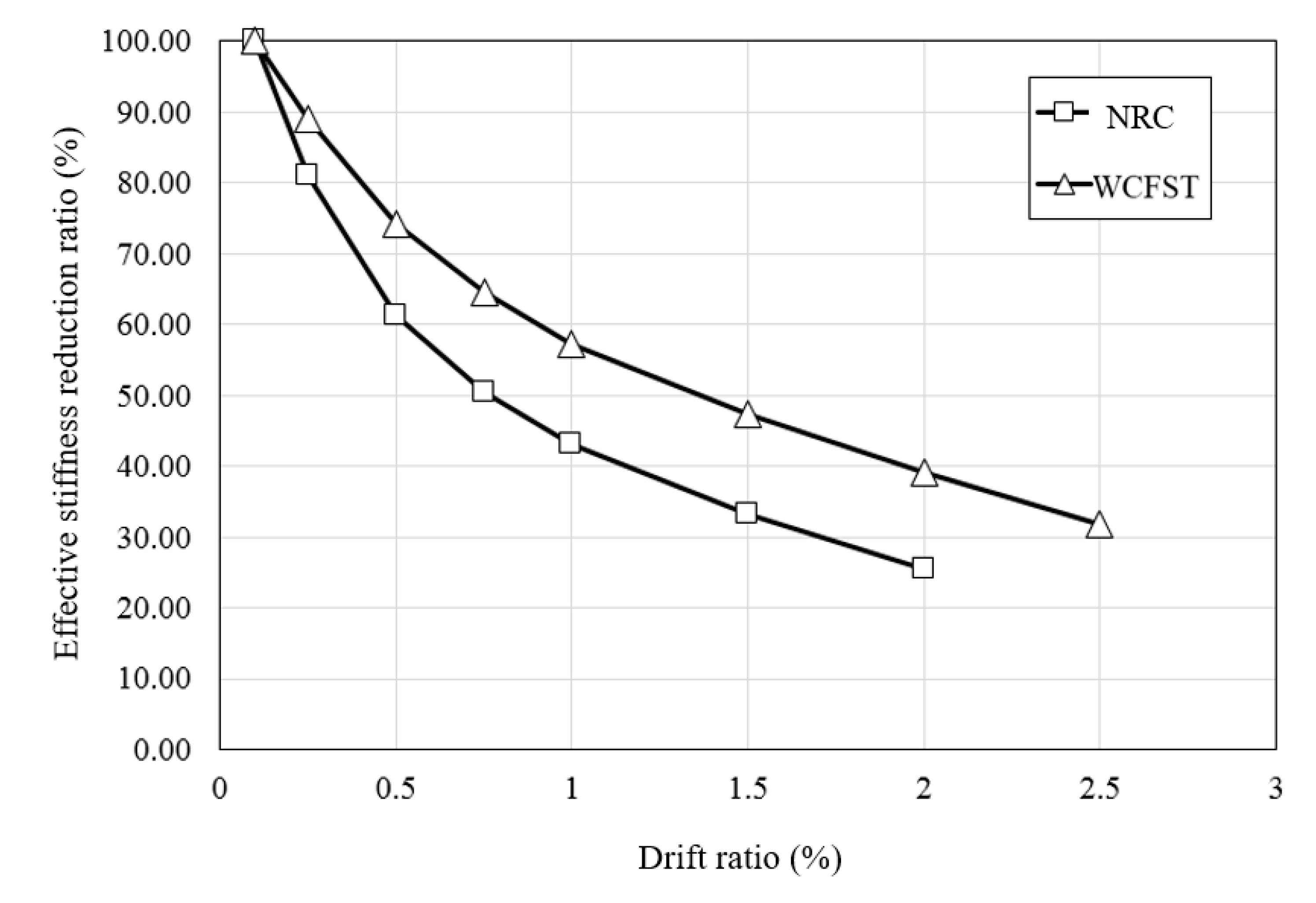
To evaluate the seismic performance of each specimen based on the test results, the effective stiffness was calculated according to the literature [17]. Effective stiffness is defined as the slope of the maximum load and displacement in the positive and negative directions of each cycle. The effective stiffness calculated by this method for each test specimen according to the drift ratio is summarized in Table 4; the rate of reduction in the effective stiffness when compared to the initial stiffness is shown in Figure 12. For the NRC test specimen without seismic details, the initial effective stiffness of 22.31 kN/mm decreased by approximately 24% at a drift ratio of 1%, where initial cracks occurred. In the case of the WCFST specimen, the initial effective stiffness was 43.24 kN/mm, about twice that of the NRC test specimen. The effective stiffness was reduced by about 15% at a drift ratio of 1% and 22% at a drift ratio of 2.5%, where failure of the specimen occurred. As a result of the experiment, the initial stiffness of the WCFST specimen attached to CFST was approximately twice that of the existing reinforced concrete test specimen. Furthermore, the WCFST specimen showed more than twice the effective stiffness of the NRC specimen when failure occurred. When the effective stiffness was equal to half of the initial effective stiffness, the drift ratios were 0.75% and 1.5% for the NRC and WCFST test subjects, respectively, indicating a greater reduction in the effective stiffness of the NRC specimens. It was confirmed that the WCFST system significantly increased the effective stiffness when compared with the existing reinforced concrete frame, and decreased the effective stiffness more smoothly after cracking occurred.

4.4. Energy Dissipation

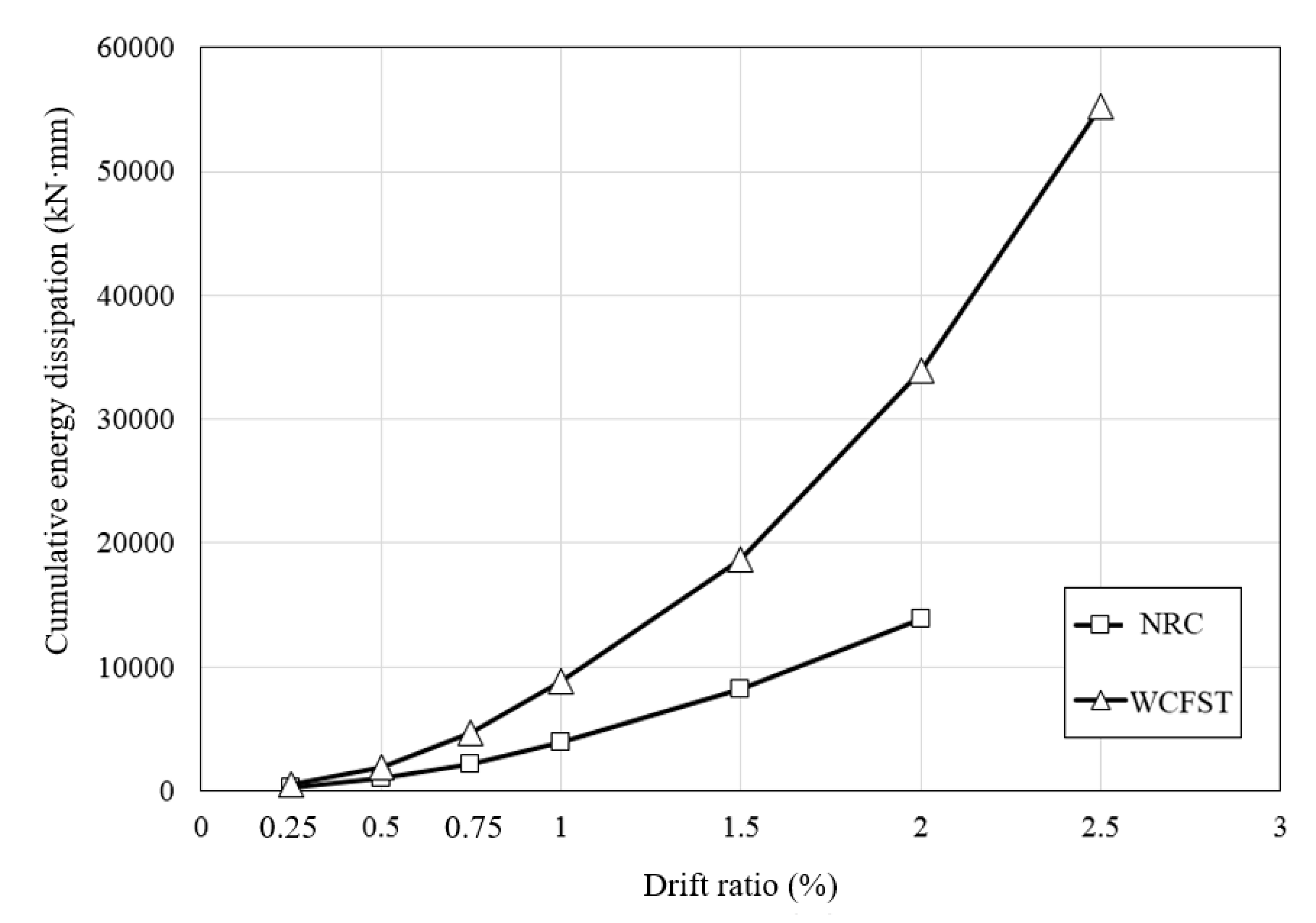
The energy dissipation capacity is a very important factor for assessing seismic performance and evaluating the ability of a structure to absorb applied seismic energy. Cumulative energy dissipation values for each test specimen are shown in Table 5 and Figure 13. Both the NRC and WCFST specimens displayed a significant increase in cumulative energy dissipation at a drift ratio of 0.75%. Such a finding indicates that the amount of seismic energy dissipated by the structures increased rapidly because of the presence of cracks at a drift ratio of 1%. In the case of the NRC specimens, the cumulative energy dissipation was calculated up to a drift ratio of 2%, as failure of the test specimen occurred as the load was applied in a positive direction at a drift ratio of 2.5%. When retrofitted with the WCFST system, the cumulative energy dissipation at a drift ratio of 0.25% was 1.8 times higher than that of the existing reinforced concrete frame. The cumulative energy dissipation gradually increased with a rise in the drift ratio, and dissipation from the WCFST specimen was about 2.5 times higher than that from the NRC specimen at a drift ratio of 2%. From the obtained results, it was confirmed that retrofitting specimens with the WCFST system was an effective strategy for improving the seismic performance by facilitating significant seismic energy dissipation.

5. Conclusions

In this study, a seismic retrofitting method using a WCFST system was proposed in order to improve the seismic performance of an RC moment-resisting frame without seismic details. One non-seismically designed reinforced concrete frame specimen and one specimen retrofitted with the WCFST system were subjected to cyclic lateral loading tests. Crack patterns, failure modes, maximum load, effective stiffness, and energy dissipation were evaluated. The conclusions from this study are as follows:
  • All of the specimens showed initial cracking at the bottom of the column at a drift ratio of 1%; the number and width of cracks at the beam-column joint and column increased as the load increased. As the drift ratio increased, the width of the shear cracks on the column increased, concrete spalling occurred, and failure of the specimens was observed at a drift ratio of 2.5%. For the NRC specimen without seismic details, the loading experiment was terminated after shear cracks were observed in the column, as the crack in the column and the overall number of cracks rapidly increased and the lateral reinforcement of the left column buckled. In the case of the WCFST specimen retrofitted according to the proposed method, the increase in shear crack width was not significant (unlike the case of the NRC specimen) and some concrete spalling was observed only at the bottom of the column. No deformation or elimination of the CFST frame was evident when the experiment was terminated.
  • The maximum loads of the NRC and WCFST specimens were 332 kN and 1013.32 kN in the positive direction, and −314.2 kN and −940.5 kN in the negative direction, respectively. When the proposed seismic retrofitting method was applied, the ability to resist lateral forces increased by about three times when compared with the existing reinforced concrete structure.
  • Unlike the NRC specimen, where the strain at the end of the beams did not increase significantly despite the increase in drift ratio, the strain of the WCFST specimen continuously increased from a drift ratio of 0.75% until failure of the specimen occurred. Such a result confirmed that the stress of the test specimen retrofitted by the WCFST system was not concentrated on the columns, but distributed throughout the specimen. When the concrete strain values of the column lateral reinforcement were examined, the NRC specimen exceeded the ultimate compressive strain of the concrete after a drift ratio of 1% was reached. The longitudinal and transverse reinforcement for both specimens yielded at drift ratios of 1.5% and 2%, respectively. In the NRC specimen, the strain increased rapidly after yield of the reinforcement and, thus, the experiment was terminated. However, in the case of the WCFST specimen, the strain gradually increased to the drift ratio at which final failure occurred after yield of the reinforcement. This observation indicated that the seismic retrofitting method using the WCFST system can distribute stress concentrated on the column evenly on the test specimen, and can increase the lateral resistance capacity of the column.
  • The test specimen with the WCFST system was confirmed to have an effective stiffness two times greater than that of the NRC specimen without seismic details. When the effective stiffness relative to the initial stiffness of each specimen reached 50%, the drift ratio was 0.75% and 1.5% for the NRC and WCFST specimens, respectively, indicating that the reduction rate of the effective stiffness for the NRC test specimen was greater than that for the WCFST specimen. The stiffness of the test specimen was increased by the WCFST seismic system retrofitting method, and the reduction rate in the effective stiffness after cracking was confirmed to be moderate.
  • The energy dissipation capacity of each test specimen was evaluated. It was found that the test specimen with the WCFST system had an energy dissipation capacity that was 2.5 times larger than that of the NRC test specimen without seismic details. Therefore, the seismic retrofitting strategy utilizing the WCFST system was also effective in enhancing strength, and was considered to be an effective retrofitting method for improving seismic performance by significantly dissipating seismic energy when compared to the existing reinforced concrete structure.
  • The proposed seismic retrofitting methods using WCFST have an economic advantage because it is possible to utilize the space during the construction period. In the case of a full building, economic loss may increase when vacancy occurs as a result of construction; therefore, the economic advantages of this proposed method can be emphasized even more. In addition, the experimental results indicate that the proposed seismic retrofitting method is expected to be effective in improving seismic performance. To provide design guidelines for the proposed method, more analytical and experimental studies are needed.

Author Contributions

Conceptualization, K.M.R. and Y.H.L.; methodology, K.M.R. and M.S.K.; validation, Y.H.L.; formal analysis, K.M.R. and M.S.K.; investigation, K.M.R. and Y.H.L.; writing—original draft preparation, K.M.R.; writing—review and editing, Y.H.L. All authors have read and agreed to the published version of the manuscript.

Funding

This work was supported by the National Research Foundation of Korea (NRF) grant funded by the Korean government (MSIT; no. 2020R1A2C2009351).

Acknowledgments

This work was supported by the National Research Foundation of Korea (NRF) grant funded by the Korean government (MSIT; no. 2020R1A2C2009351). This support is gratefully acknowledged.

Conflicts of Interest

The authors declare no conflict of interest.

References

  1. FEMA-547. Techniques for the Seismic Rehabilitation of Existing Buildings; Building Seismic Safety Council for the Federal Emergency Management Agency: Washington, DC, USA, 2006.
  2. Choi, S.W. Investigation on the seismic retrofit positions of FRP jackets for RC frames using multi-objective optimization. Compos. Part. B Eng. 2017, 123, 34–44. [Google Scholar] [CrossRef]
  3. Ahn, N.; Kim, M.S.; Song, S.E.; Lee, Y.H. Seismic performance of reinforced concrete frames retrofitted with inserted steel frame and adhered waved steel panel. J. Vibroeng. 2016, 18, 1041–1051. [Google Scholar]
  4. Al-Salloum, Y.A.; Siddiqui, N.A.; Elsanadedy, H.M.; Abadel, A.A.; Aqel, M.A. Textile-reinforced mortar versus FRP as strengthening material for seismically deficient RC beam-column joints. J. Compos. Constr. 2011, 15, 920–933. [Google Scholar] [CrossRef]
  5. Shin, J.; Scott, D.W.; Stewart, L.K.; Yang, C.S.; Wright, T.R.; Des Roches, R. Dynamic response of a full-scale reinforced concrete building frame retrofitted with FRP column jackets. Eng. Struct. 2016, 125, 244–253. [Google Scholar] [CrossRef] [Green Version]
  6. Attari, N.; Youcef, Y.S.; Amziane, S. Seismic performance of reinforced concrete beam–column joint strengthening by frp sheets. Structures 2019, 20, 353–364. [Google Scholar] [CrossRef]
  7. Cosgun, C.; Cömert, M.; Demir, C.; İlki, A. Seismic Retrofit of Joints of a Full-Scale 3D Reinforced concrete Frame with FRP Composites. J. Compos. Constr. 2019, 23, 04019004. [Google Scholar] [CrossRef]
  8. Pohoryles, D.A.; Melo, J.; Rossetto, T.; Varum, H.; Bisby, L. Seismic retrofit schemes with FRP for deficient RC beam-column joints: State-of-the-art review. J. Compos. Constr. 2019, 23, 03119001. [Google Scholar] [CrossRef] [Green Version]
  9. Ozcelik, R.; Akpınar, U.; Binici, B. Seismic retrofit of deficient RC structures with internal steel frames. Adv. Struct. Eng. 2011, 14, 1205–1222. [Google Scholar] [CrossRef]
  10. Tafakori, E.; Banazadeh, M.; Jalali, S.A.; Tehranizadeh, M. Risk-based optimal retrofit of a tall steel building by using friction dampers. Struct. Des. Tall Spec. Build. 2013, 22, 700–717. [Google Scholar] [CrossRef]
  11. Lee, C.H.; Ryu, J.; Kim, D.H.; Ju, Y.K. Improving seismic performance of non-ductile reinforced concrete frames through the combined behavior of friction and metallic dampers. Eng. Struct. 2018, 172, 304–320. [Google Scholar] [CrossRef]
  12. Dong, Y.R.; Xu, Z.D.; Li, Q.Q.; Xu, Y.S.; Chen, Z.H. Seismic behavior and damage evolution for retrofitted RC frames using haunch viscoelastic damping braces. Eng. Struct. 2019, 199, 109583. [Google Scholar] [CrossRef]
  13. Eldin, M.N.; Dereje, A.J.; Kim, J. Seismic retrofit of RC buildings using self-centering PC frames with friction-dampers. Eng. Struct. 2020, 208, 109925. [Google Scholar] [CrossRef]
  14. Vafaei, M.; Sheikh, A.M.O.; Alih, S.C. Experimental study on the efficiency of tapered strip dampers for the seismic retrofitting of damaged non-ductile RC frames. Eng. Struct. 2019, 199, 109601. [Google Scholar] [CrossRef]
  15. Han, L.H.; Liao, F.Y.; Tao, Z.; Hong, Z. Performance of concrete filled steel tube reinforced concrete columns subjected to cyclic bending. J. Constr. Steel Res. 2009, 65, 1607–1616. [Google Scholar] [CrossRef]
  16. Lee, C.H.; Kang, T.H.K.; Kim, J.W.; Song, J.K.; Kim, S. Seismic Performance of Concrete-Filled Tube Column-Reinforced Concrete Slab Connections with Shearhead Keys. ACI Struct. J. 2019, 116, 233–244. [Google Scholar]
  17. Tsonos, A.G. Lateral load response of strengthened reinforced concrete beam-to-column joints. ACI Struct. J. 1999, 96, 46–56. [Google Scholar]
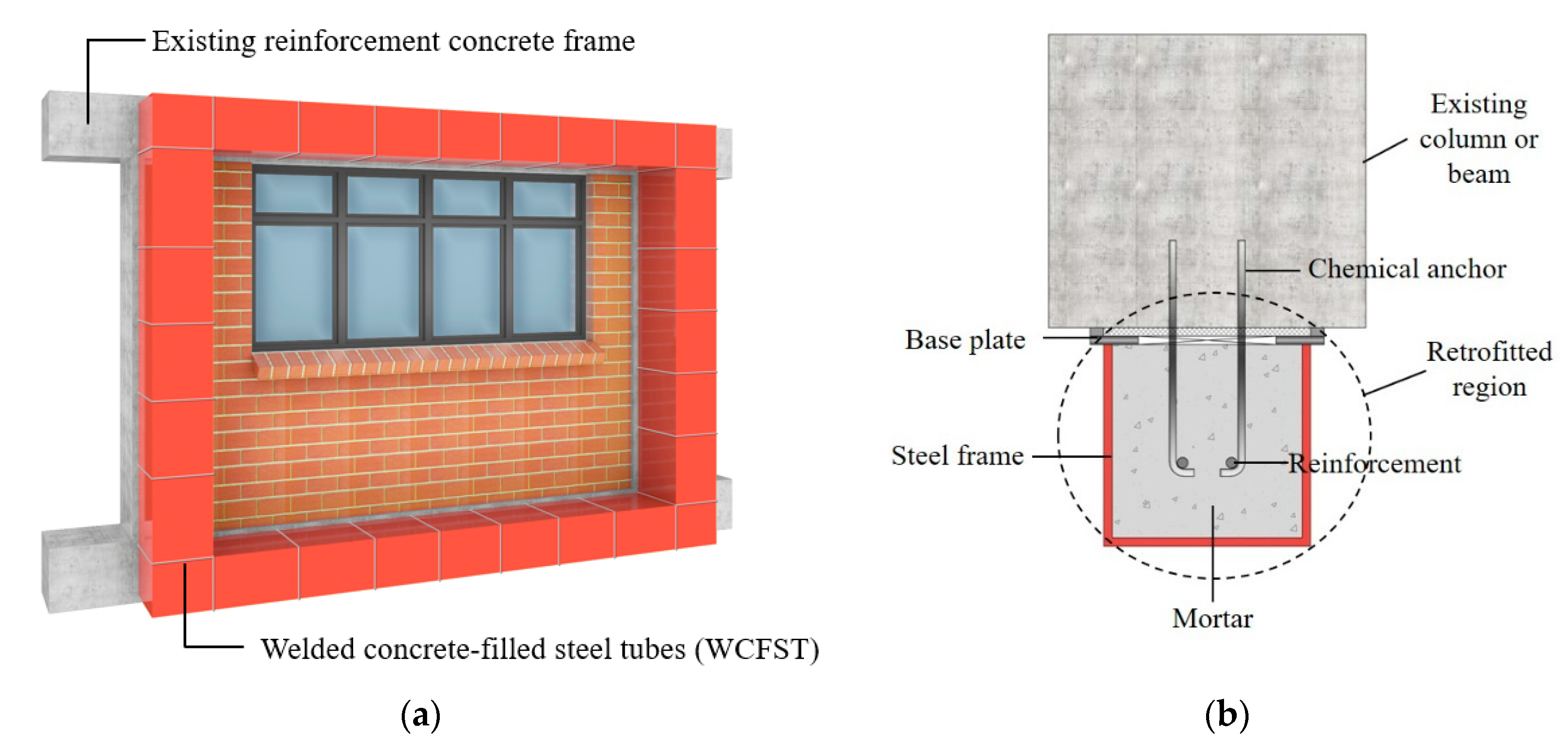
Figure 1. Welded concrete-filled steel tube (WCFST) retrofitting scheme for the reinforced concrete (RC) frame: (a) front elevation and (b) section.
Applsci 10 07061 g001
Figure 2. Construction process for retrofitting using the WCFST system: (a) installation of base plates, (b) bonding of base plates using a chemical anchor and placing of reinforcement, and (c) installation of a CFST frame.
Applsci 10 07061 g002
Figure 3. Details of the reinforced concrete frame (mm): (a) front view and (b) vertical cross-section.
Applsci 10 07061 g003
Figure 4. Details of the CFST frame in the WCFST specimens (mm): (a) vertical cross-section and (b) horizontal cross-section.
Applsci 10 07061 g004
Figure 5. Installation of the CFST frame on the WCFST specimen: (a) drilling of holes in the column, (b) bonding of base plates using a chemical anchor, and (c) welding of base plate and CFST frame.
Applsci 10 07061 g005
Figure 6. Experimental setup for the cyclic loading test: (a) schematic test setup and (b) view of the test setup.
Applsci 10 07061 g006
Figure 7. Loading protocol.
Applsci 10 07061 g007
Figure 8. Load–displacement curves: (a) non-seismic reinforced control specimen (NRC) and (b) WCFST.
Applsci 10 07061 g008
Figure 9. Envelope curves.
Applsci 10 07061 g009
Figure 10. Strain at the end of the beam: (a) strain of the longitudinal steel at the end of the beam, (b) strain of the stirrup at the end of the beam, and (c) strain of the CFST frame at the end of the beam in the WCFST specimen.
Applsci 10 07061 g010
Figure 11. Strain at the end of the column: (a) strain of the concrete at the end of the column, (b) strain of the longitudinal steel at the end of the column, (c) strain of the transverse steel at the end of the column, and (d) strain of the CFST frame at the end of the column.
Applsci 10 07061 g011aApplsci 10 07061 g011b
Figure 12. Effective stiffness reduction ratio when compared to the initial stiffness.
Applsci 10 07061 g012
Figure 13. Cumulative energy dissipation from the specimens.
Applsci 10 07061 g013
Table 1. Details of the specimens.
ElementsDimension (mm)Reinforcement
LongitudinalTransverse
Column350 × 500 × 28508-D19, 2-D16D10@300 mm
Upper beam250 × 450 × 32006-D22Mid: D10@300 mm
End: D10@200 mm
Lower beam350 × 600 × 32006-D22Mid: D10@300 mm
End: D10@200 mm
Foundation800 × 500 × 435045-D22D16@130 mm
Table 2. Crack patterns and failure in the specimens.
Drift Ratio (%)Specimens
NRCWCFST
1.5 Applsci 10 07061 i001 Applsci 10 07061 i002
2.0 Applsci 10 07061 i003 Applsci 10 07061 i004
2.5 Applsci 10 07061 i005 Applsci 10 07061 i006
NRC: Non-seismic reinforced control specimen, WCFST: Welded concrete-filled steel tubes specimen.
Table 3. Comparison of loads according to the drift ratio.
Drift Ratio (%)Load (kN)Load Ratio of WCFST to NRC
NRCWCFST
Positive Loading Negative LoadingPositive Loading Negative Loading Positive Loading Negative Loading
0.167.70−59.47124.86−121.621.842.05
0.25134.25−123.20280.65−267.542.092.17
0.5201.80−187.75475.00−440.112.352.34
0.75248.33−231.71621.8−569.582.502.46
1.0283.10−265.51738.58−673.652.612.54
1.5323.96−308.32910.77−836.072.812.71
2.0332.00−314.21995.88−929.293.002.96
2.5311.39-1013.32−940.5 03.25-
Table 4. Comparison of effective stiffness according to the drift ratio.
Drift Ratio (%)Effective Stiffness (kN/mm)Effective Stiffness Ratio of WCFST to NRC
NRCWCFST
0.122.3143.241.94
0.2518.0738.472.13
0.513.6732.112.35
0.7511.2327.872.48
1.09.6224.782.58
1.57.4020.432.76
2.05.6716.892.98
2.5-13.71-
Table 5. Comparison of cumulative energy dissipation according to the drift ratio.
Drift Ratio (%)Cumulative Energy Dissipation (kN·mm)Cumulative Energy Dissipation Ratio of WCFST to NRC
NRCWCFST
0.1---
0.25246.26453.451.84
0.5962.211883.781.96
0.752176.844641.062.13
1.03956.358805.302.23
1.58147.5218,723.152.30
2.013,864.0433,974.652.45
2.5-55,261.46-