Article

A Novel Method for Designing Motion Profiles Based on a Fuzzy Logic Algorithm Using the Hip Joint Angles of a Lower-Limb Exoskeleton Robot

Department of Mechanical Engineering, Yonsei University, Seoul 03722, Korea
*
Author to whom correspondence should be addressed.
Appl. Sci. 2020, 10(19), 6852; https://doi.org/10.3390/app10196852
Submission received: 13 August 2020 / Revised: 18 September 2020 / Accepted: 24 September 2020 / Published: 29 September 2020

Abstract

:
In this study, a novel method for designing real-time motion profiles based on a weighted fuzzy logic algorithm for an exoskeleton robot was proposed. When developing exoskeleton robots, it is important that they can identify a wearer’s motion intent in real time; therefore, we produced the motion profiles of an exoskeleton robot knee joint angles using hip joint angles and plantar pressure sensors. Two types of sensors were used to design the robot’s knee estimation angle profiles in real time—namely, hip joint angles to design the fuzzy logic algorithm and plantar pressure sensors to classify the robot’s gait phase. In the fuzzy set, four fuzzy inputs were produced through the hip joint angles; then, four fuzzy outputs were implemented based on the fuzzy inputs using 68 predefined rule bases in the fuzzy inference. The fuzzy outputs were used as the basis for calculating the motion profiles during the defuzzification. To adjust the knee angle of the robot, the weighted values were assigned to each hip joint angle section. To validate the proposed algorithm, we conducted two experiments—namely, the exoskeleton robot with and without an actuator. The method was verified through experiments showing that the motion profiles estimated the robot’s knee angles close to the desired angles.

1. Introduction

Industrial robots for mass production and medical robots using advanced technology have been transforming to expand human living spaces and improve the quality of life. Robots have been developed in various forms to coexist with humans, such as exoskeleton robots. These exoskeleton robots are essential production work elements in the future on industrial or construction sites where workers repeatedly carry heavy objects. Even if the object is not heavy, moving objects repeatedly throughout the day can accumulate fatigue and reduce productivity. Additionally, according to one survey, the proportion of elderly persons in 2050 is expected to double compared to 2015 [1]. Due to the increasing aging society, the demand for assistance robots that can support daily life activities for the elderly is expected to increase. Therefore, an exoskeleton robot can help to increase worker productivity and reduce the risk of injury and fatigue and can also assist with human movement, such as medical applications. An exoskeleton robot has been defined as nonmedical applications and medical applications [2]. In other words, the robot goes by various names, such as a powered exoskeleton for military and industrial purposes [3,4,5] and power-assist suit for rehabilitation and assistive purposes [6,7,8]. Depending on whether the target of the application involves medical or nonmedical purposes, the actuation technologies [9,10,11], the exoskeleton mechanism [12,13], the sensor type [14,15], and the wearer intention algorithm should be chosen appropriately. As such, exoskeleton robots will be able to help with our daily lives across various fields in the future.
It is necessary to identify a wearer’s intention to control exoskeleton robots based on the wearer’s intention algorithm. However, misalignment occurs if the link lengths and joint positions between the human and robot are different. This misalignment is one of the factors that adversely affects the wearer’s intent. Additionally, it is difficult to grasp a wearer’s intention owing to the mathematical relationship between a human lower muscular system and a lower-limb exoskeleton system. To overcome these difficulties, various algorithms based on torque control have been applied to a lower-limb exoskeleton robot. Fuzzy logic is one of the most effective methods for managing the complexity and uncertainties, because the system tolerates inaccurate information, is flexible, and can easily modify the rules used. For instance, the fuzzy logic method and proportional-based fuzzy (PBF) algorithm are used to identify the wearer’s intention in real time, and an algorithm is applied to the exoskeleton robot [16,17,18]. In addition, the terrain feature estimation method using a contact point between the limb exoskeleton and ground is used to estimate the slope and elevation [19]. However, in order to measure a force between a wearer and a robot, there is a disadvantage of minimizing the contact point, because an expensive force sensor must be attached to every contact point. Therefore, the purpose of the study is to estimate and control the wearer’s motion intention while overcoming these limitations.
Due to the misalignment and the complex mathematical relationship between the human lower muscular system and a lower-limb exoskeleton system, it is difficult to grasp the intention of the wearer, resulting in an inefficient system performance. In this study, we propose a design for the motion profiles to control an exoskeleton robot’s knees based on a weighted fuzzy logic algorithm using the hip joint angles. To design the proposed algorithm, preliminary work on the gait phases was required to analyze the knee of an exoskeleton robot. One leg joint was considered to have four degrees of freedom (4DoFs), the hip and ankle joint angles of the exoskeleton robot were designed to be passive joints, and the knee joint angle worked as an active joint. The hip and ankle angle joints could move at any angle of freedom of the wearer, but the knee angle of the wearer was estimated by the proposed algorithm in the active joint. The proposed algorithm was used as a position input to control the exoskeleton robot’s knee. In other words, the knee angle of the wearer was estimated using the hip joint and the foot pressure sensors. Since the sagittal plane is mainly used for walking, it is possible to sufficiently grasp the intention of the wearer by using the hip joint angle. For this, two types of physical human–robot interaction (pHRI) sensors were used: (1) absolute rotary encoders on the hip and knee joint axis of the exoskeleton robot and (2) the plantar pressure sensors on the foot for the gait phase classification. When the pressure sensor measurements were higher than the set threshold, this was defined as the stance phase, and fuzzy inference for the stance phase was applied. In contrast, when these measurements were lower than the set threshold, fuzzy inference for the swing phase was applied. The encoder sensors measured the hip joint angle, and they were used as crisp inputs to yield four fuzzy input conditions through the linear transfer functions in the fuzzy set. Four fuzzy inputs were selected though the minimum in AND operation from the hip encoder sensors. After we determined the minimum in AND operation, four fuzzy inputs were used as the input for the fuzzy inference. Four fuzzy output values were implemented using the four inputs and 68 predefined rule bases in the fuzzy inference. The rule bases were divided into swing-phase rule bases and stance-phase rule bases, and they were designed based on the gait analysis of the wearer in locomotion. A crisp output was calculated using the selected four fuzzy output values and weighted values based on the center of area (CoA) method found in the Mamdani method. The criterion of the weighted values was assigned using the angle section to estimate the knee joint angle. The crisp output created an estimated motion profile, which was used as a position input to control the exoskeleton robot’s knee. The proposed algorithm is called a high-level system. A high-level system transmits the motion profiles of a robot’s knee to the low-level system of the developed electro-hydraulic actuator (EHA) system [9,10], such that the two systems become combined. The proposed algorithm was verified through experiments, showing that it alleviates the difficulty of mathematically expressing complex structures. The algorithm was used to verify the motion profiles in real time to estimate the knee’s joint angle in two experiments. The first experiment was performed without the EHA for the exoskeleton knee angle estimation, and in the second experiment, the motion profiles of the knee were estimated in real time, and the knee was controlled using the EHA. Through the experiments, it was shown that the proposed method accurately estimated the knee joint angle of the exoskeleton robot.
The remainder of this paper is structured as follows. In Section 2.1, each component of the designed exoskeleton robot is briefly described, and the gait analysis of the exoskeleton robot is explained. Section 2.2 describes the proposed estimation design process for the motion profiles. Section 2.3 explains the method of applying the proposed algorithm to the exoskeleton robot. In Section 3, the experimental configuration and two experimental results are described. The conclusions of the results are presented in the last section.

2. Methods

2.1. Design of an Exoskeleton Robot with an Electro-Hydarulic Actuator System

We developed the lower-limb exoskeleton robot as shown in Figure 1. This exoskeleton consisted of the EHA system developed using the bidirectional piston pump [16], the wearer’s shoe for detecting the wearer’s intention, a 200-MHz main controller unit (MCU), and a 6061-aluminum frame body. Straps and buckles were used to fix the waist, shoulders, thighs, and ankles. One leg was designed with 4DoFs—namely, the hip, knee, and ankle joints. The hip and ankle joints were designed to be passive with 2DoFs in the sagittal and frontal planes and 1DoF in the sagittal plane. A 12-bit absolute position could rotate 0 to 360 ° clockwise or counterclockwise, and it was attached to every angular joint measuring an angle. The hip joint angle sensors were calibrated to 0 ° in the robot’s standing position. If the knee rotated counterclockwise about the robot’s standing position, it was defined as a positive angle, and if it rotated clockwise, it was defined as a negative angle. A 120-mm hydraulic cylinder connected the hip and knee joints, such that the knee joint was operated by the cylinder, which was designed to be an active joint with 1DoF. Let x r represent the length of the cylinder stroke displacement between the hip joint and the knee joint, l x = [ l 1 , l 2 , l 6 ] represent the length of the lower-limb exoskeleton, and θ 2 represent the knee joint angle. Using Pythagoras’s theorem, we obtained the lengths of two l 1   = 308 mm and l 4 = 102 mm. Since the lengths l 2 ,   l 3 ,   l 5 , and   l 6 were constant, x r was changed by the angle of θ 2 , according to the second cosine law [11].
x r 2 = l 1 2 + l 4 2 2 · l 1 · l 4 · cos ( θ 2 α )
Load cell sensors were installed under the insole to distinguish between the swing and stance phases during walking, and the load cell sensors were installed in the order of the heel, metatarsal, and toe between the top of the plastic material and the bottom of the rubber. They were able to measure up to 100 kfg, and the sensors were 30 mm in diameter and 5 mm in height. Two fastening straps were used on the front and back of the wearer’s shoe.
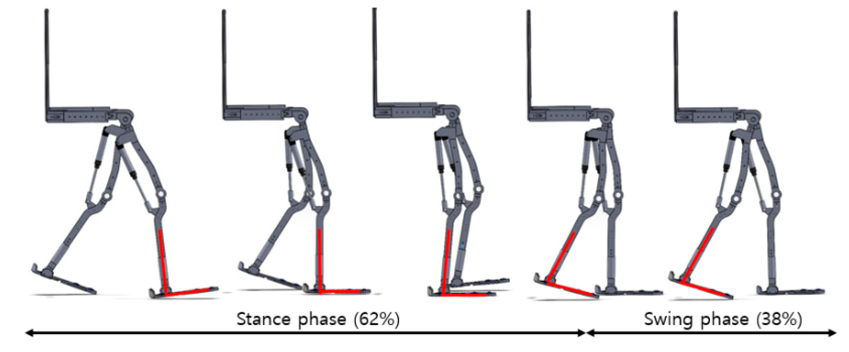
The gait phase was divided into two phases—namely, a stance phase and a swing phase. When the shoe is on the ground, it is called the stance phase; when the shoe is in the air, this is called the swing phase, as shown in Figure 2. In previous studies of the gait cycle, the stance phase was approximately 62%, while the rest was represented by the swing phase [17].
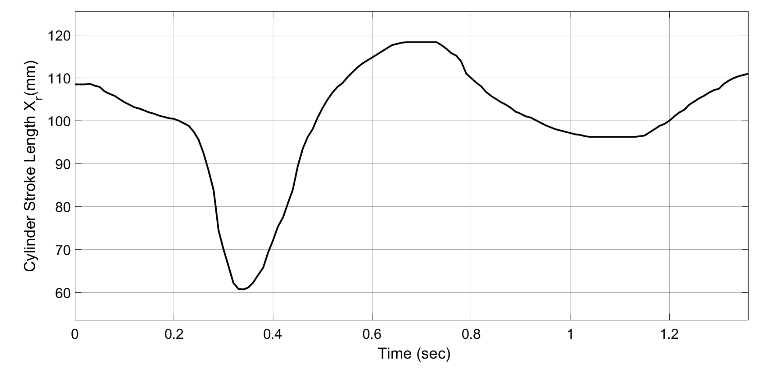
For the analysis of the robot’s knee, the gait experiment was conducted at intervals of 40 cm in width. According to the analysis of the displacement of the cylinder length in Figure 3, there was a swing phase from 0.2 to 0.6 s, and after 0.6 s, there was a stance phase. The stroke displacement x r was changed by the knee joint angle θ 2 of the exoskeleton robot; therefore, by substituting the raw data on the knee joint angle into the second cosine law (Equation (1)), the displacement of the cylinder stroke x r could be calculated. The knee joint angle θ 2 was changed by approximately 50 ° between 0 ° and 55 ° in the experiment. In the swing phase, the displacement of the cylinder rod x r was approximately 60 mm. When the knee joint was stretched in the pre-stance phase, and the cylinder rod reached approximately 115 mm. During the stance phase, the displacement of the stroke length was maintained between 90 and 110 mm.

2.2. Design of a Real-Time Motion Profile for the Exoskeleton Robot’s Knee Joint Angle

The purpose of our study was to design a real-time motion profile for the knee joint angle using the cylinder rod. To design this, a weighted fuzzy logic algorithm using the hip joint angles of the exoskeleton robot was proposed. Two crisp inputs were used as inputs for the real-time estimation algorithm based on the hip joint angles of the exoskeleton robot. The fuzzy logic structure consists of the crisp input section, fuzzification, fuzzy inference, and defuzzification. The overall structure is expressed as shown in Figure 4 below. In the crisp input section, two input values go through a trapezoidal and triangular function membership, and four minimum fuzzy input values are then determined. The fuzzy outputs are determined in fuzzification and the fuzzy rule base using the 68 predefined rule bases and fuzzy inputs. The weighted values, which connect the fuzzy inference and defuzzification, are assigned at 10 ° intervals of the hip joint and used together with the CoA method and the weighted values.
In the crisp input section, we designed a linear transfer function based on the analysis of the gait phase. Both hip joint angle ranges were set to −10 ° to 40 ° . These ranges were split into six divisions for each leg: the linguistic terms LN, LZR, LP, LPS, LPM, and LPL represent negative, zero, positive, positive small, positive medium, and positive large for the left hip joint angle, while RN, RZR, RP, RPS, RPM, and RPL indicate negative, zero, positive, positive small, positive medium, and positive large in the right hip joint angle. Two crisp inputs were converted into four fuzzy inputs using the linear transfer functions below.
u ( x , ; α , β , γ , δ ) f o r   t r a p e z o d i a l   f u n c t i o n = [ 1 x α β α δ x δ γ 0 0 f o r   β < x γ f o r   α   x   β f o r   γ < x δ   f o r   x < α f o r   x > δ ]
u ( x ; α , β , δ ) f o r   t r i a n g u a l r   f u n c t i o n   = [ 0 x α β α δ x δ β 0   f o r   x < α f o r   α x β f o r   β < x   δ x > δ ]
The parameters α and δ represent the lower boundary of the x-axis coordinates in the fuzzy set, while β and γ represent the upper boundary. The membership function distributions of the variables were designed to be at intervals of 20°. Through the analysis of the gait data obtained during locomotion, the angles of the hip joints were assigned membership functions ranging from −10° to 40°. Depending on the hip joint angle within the set range, either one or two fuzzy inputs are produced. Each hip joint has two fuzzy input conditions according to the membership functions, and a total of four fuzzy input conditions are produced. In Figure 5, the membership function is expressed as an algorithmic diagram using the trapezoidal and trigonometric functions (Equations (2) and (3)) in fuzzification.
The diagram represents the process used to obtain the fuzzy inputs. The four fuzzy inputs in fuzzification are determined using the outputs of the minimum value of the fuzzy function below. These minimum fuzzy inputs are considered the output of fuzzification:
{ F u z z y   i n p u t 1 = m i n ( i n p u t 1 1 , i n p u t 2 1 ) F u z z y   i n p u t 2 = m i n ( i n p u t 1 1 , i n p u t 2 2 ) F u z z y   i n p u t 3 = m i n ( i n p u t 1 2 , i n p u t 2 1 ) F u z z y   i n p u t 4 = m i n ( i n p u t 1 2 , i n p u t 2 2 ) }
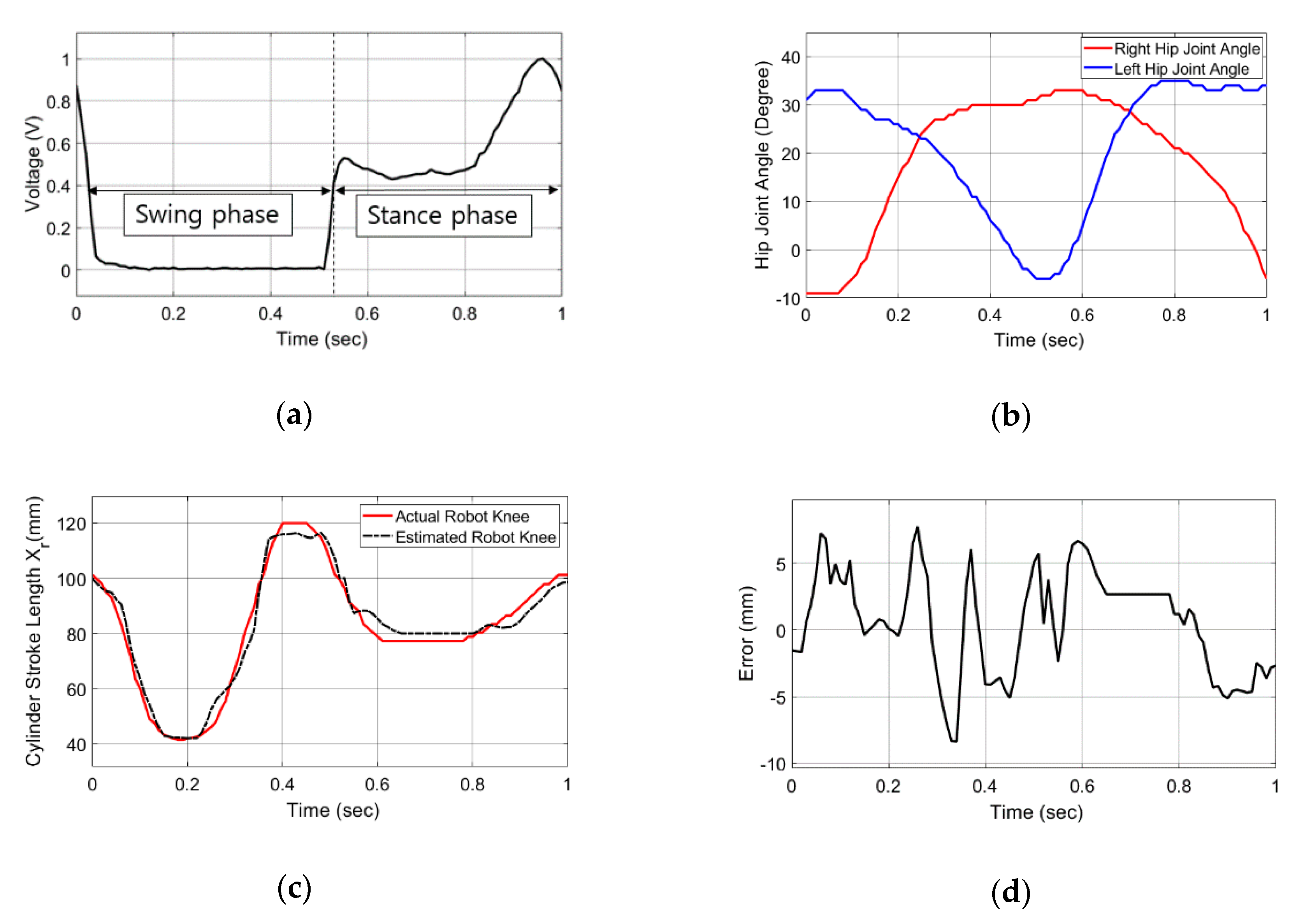
There are six linguistic terms for each of input1 and input2. Input1 refers to the left hip joint angle, while the input2 refers to the right hip joint angle. Based on the two hip joints, we designed an algorithm that estimates the knee of an exoskeleton robot. To determine the fuzzy rules in the fuzzy inference system (FIS), we created a dataset of walking experiments wearing the exoskeleton robot. This dataset consisted of hip joint angle values, knee joint angle values, and foot pressure values. Then, we evaluated the fuzzy rules with the hip joint angle values and pressure values in the simulation, and the estimated outputs were comparted to the actual outputs of the knee joint angle. Finally, we measured the error between the estimated outputs and the actual outputs and determined whether the fuzzy rules for the swing and stance phases were well-chosen or not. In other words, we tested the rule set through a trial and error method and analysis of the gait phase in the simulation. The simulation results are shown in Figure 6 below. The swing phase from 0 to 0.55 s and the stance phase from 0.55 to 1 s are shown in Figure 6a,b. Figure 6c shows the comparison of the estimated and actual outputs, and Figure 6d shows the measurement error for the two outputs.
Therefore, we multiplied the six terms of input1 by the six terms of input2 to get a total of 36 rule bases. By combining the rule bases for the swing phase and the rule bases for the stance phase, a total of 68 rule bases were designed. Table 1 and Table 2 below show the 34 rule bases of the motion profile for the swing phase and stance phase, respectively.
The trigonometric membership function for the cylinder rod stroke was designed using five fuzzy sets, i.e., very low (VL), low (L), medium (M), high (H), and very high (VH). The output membership function was designed using a trial and error method in the fuzzy inference, and the trigonometric function is shown in Figure 7.
Figure 5 and Figure 7 display similar meanings regarding the membership functions, but the membership functions were expressed differently. The whole range of fuzzy sets was set from 0 to 120 mm for the output. The 68 rule bases are given in the following form in the fuzzy inference:
{ Rule   1   IF   Input 1   is   LN   and   Input 2   is   RN ,   THEN   x i   is   VL Rule   34   IF   Input 1   is   LPL   and   Input 2   is   RPL ,   THEN   x i   is   V }   for   the   swing   phase   and { Rule   1   IF   Input 1   is   LN   and   Input 2   is   RN ,   THEN   x i   is   VH Rule   34   IF   Input 1   is   LPL   and   Input 2   is   RPL ,   THEN   x i   is   M }   for   the   stance   phase .
In fuzzy inference, the fuzzy outputs are implemented by the rule bases and the fuzzy inputs, and in defuzzification, the outputs are used as the input values to design the motion profiles using the CoA method and the weighted values. The weighted values were assigned from 1 to 0.5, depending on the angular range. The motion profiles of the exoskeleton robot’s knee estimation are expressed using the following equation:
Motion   profile = x m i n x m a x w i · f ( x ) · x d x x m i n x m a x f ( x ) d x
Considering the dynamic change and noise of the system, we used a moving average filter:
x ^ r =   x ¯ r 1 +   x r x r k k
The term x ¯ r 1 is the previous moving average, the term x r k is the oldest data, x r is the most recent data, and k is the number of data points. The crisp output is filtered by the moving average filter shown in Equation (7). The resulting value obtained through the filter x ^ r is used as a position input to control the exoskeleton robot’s knee joint angle. The proposed algorithm is called a high-level system.

2.3. The Proposed Algorithm with a Controller

The estimated input signal x ^ r is used to control the robot’s muscle strength using the developed EHAs. The EHA system for increasing the muscle strength of the exoskeleton robot is called a low-level system. In a previous work, modeling of the developed EHAs of an exoskeleton robot was expressed as follows [9]:
x r = k p ϕ ω A t   C s A s A t 2 | P p A P p B | ρ [ ( P p A P p B ) 2 + P cr 2 ] 1 / 4 F t A A t ( V 0 2 β e s + C t ) ( V 0 2 β e M A A t ) s 3 + ( V 0 2 β e B A A t + C t M A A t ) s 2 + ( 1 + F t 2 A t β e ) s
Due to uncertain fluid parameters and unknown model parameters in the hydraulic actuator, a nonlinear controller was developed to minimize the uncertainties. The developed EHA controller for an exoskeleton robot can be written as follows [9]:
u = a p a ˜ ^ 2 x 3 a p a ˜ ^ 3 x 2 a p a ˜ ^ 4 x a p a ˜ ^ 1 r a p a ˜ ^ 5   3 λ e ¨ 3 λ 2 e ˙ λ 3 e k ·   sat ( s ϕ )
The ankle and hip joints of the exoskeleton robot operate as passive joints, and the knee joint operates as an active joint. Based on the plantar pressure sensors in the wearer’s shoe and hip joint angles, the motion profiles x ^ r are designed in real time for walking, and the EHA system controls the motion profiles. Two subsystems are combined: the high-level system of the proposed estimation algorithm and the low-level system of the EHAs developed in a previous work [9], as shown in Figure 8.

3. Experiment

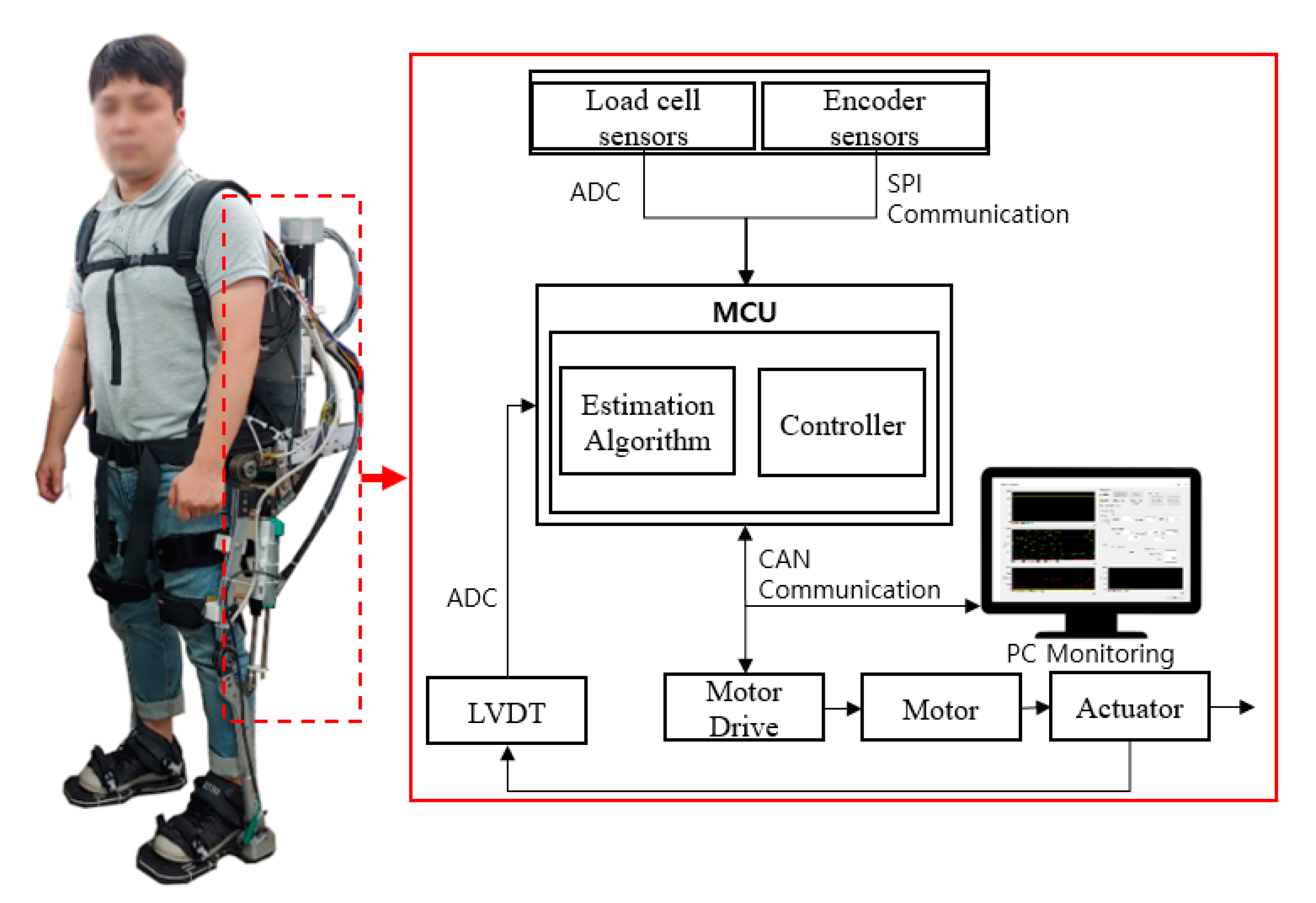
To validate the feasibility of the proposed method in terms of estimating the wearer intentions in real time, a walking experiment using the EHA system and a sit-to-stand movement was performed. A schematic diagram of the experimental setup of the exoskeleton robot system is shown in Figure 9 below.
The motion profile was designed based on the angle of the hip joint and the pressure on the sole. It was connected to a 12-bit analog-to-digital converter between the TI f28379d main controller unit and the load cell sensors, and the absolute hip joint angles were connected by serial peripheral interface communication. Graphic user interface monitoring was also developed with the Microsoft foundation class, which can save up to 2000 data points of each variable for 20 s. Through the proposed method with the sensor input values, the wearer’s intention was identified in real time, and a gait profile was created. The estimated gait profile was used as a reference value to control the knee joint position.
The motion profile was used as a position input to control the knee joint of the exoskeleton robot. We confirmed whether the proposed algorithm estimates the knee displacement in the gait phase by wearing an exoskeleton robot without an actuator.
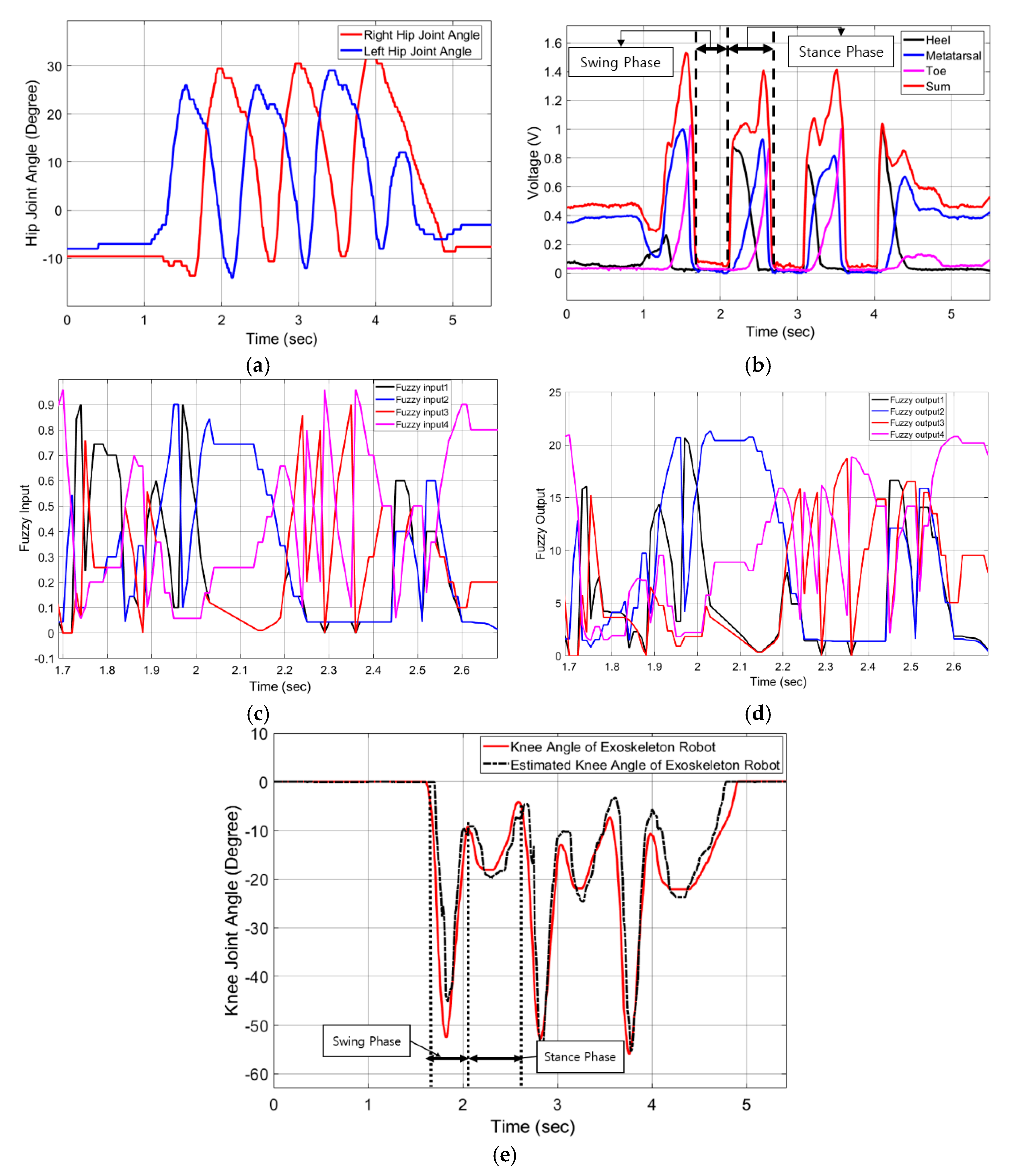
When walking at intervals of approximately 40 cm in width, the hip joint angles showed an angle change of between −10 ° and 30 ° . The left and right hip joint angles were used as input values for a fuzzy set in Figure 10a. Figure 10b shows the heel, metatarsal, and toe plantar pressures. When the sum of the heel, metatarsal, and toe plantar pressures, after converting to a voltage, was less than 0.1 V, the stance phase rule bases were used; otherwise, the swing phase rule bases were used in the fuzzy inference. The fuzzy inputs and outputs for the swing phase from 1.7 to 2.1 s and for the stance phase from 2.1 to 2.7 s, are shown in Figure 10c,d, where the fuzzy outputs using 68 predefined rule bases and fuzzy inputs were implemented. Figure 10e compares the knee joint angle of the robot and the estimated knee joint angle. During the swing phase, the angular displacement of the knee varied from 0 ° to 55 ° . On the other hand, the stance phase exhibited a change of angular displacement from 0 ° to 30 ° .
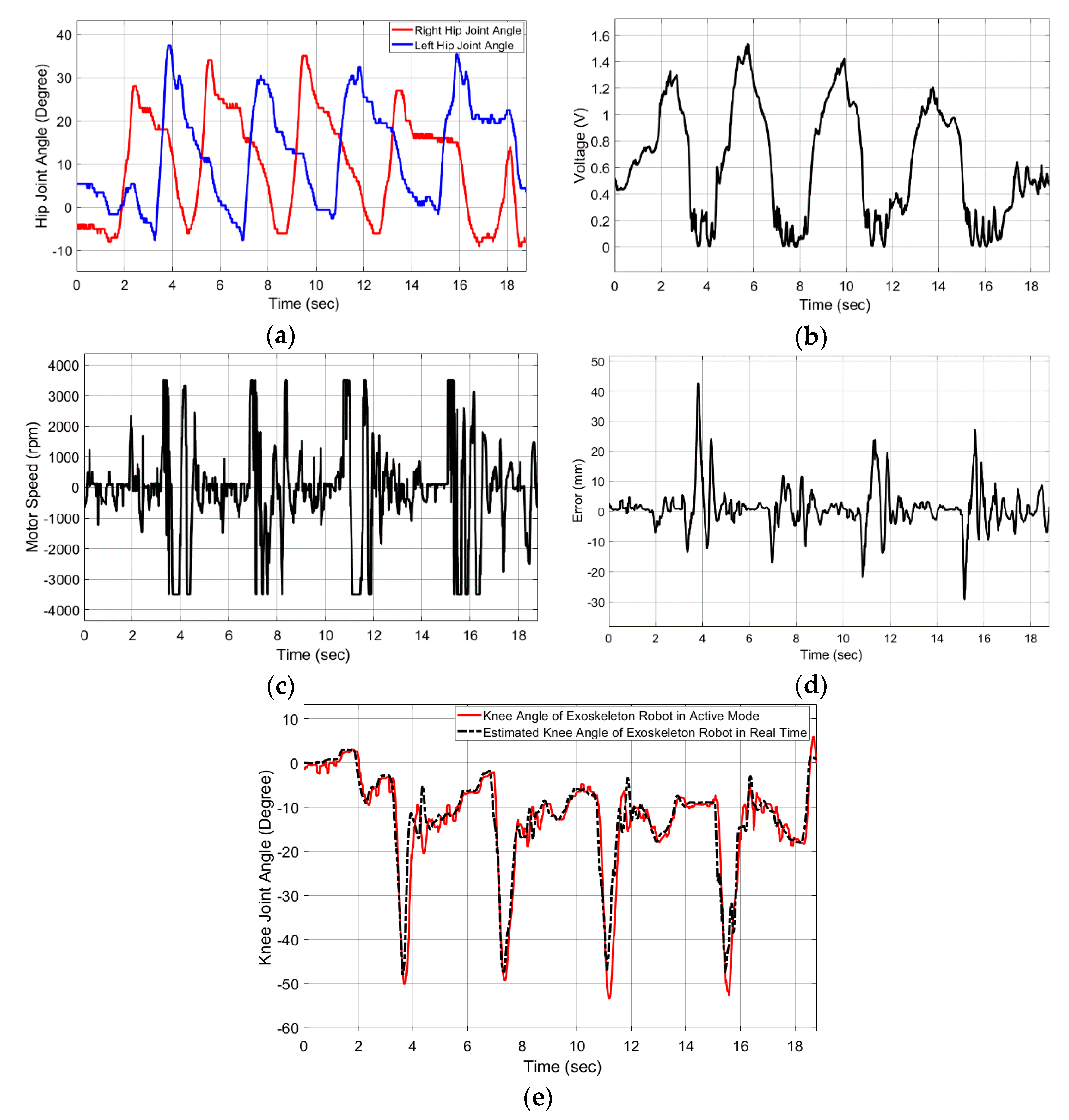
The experimental data of the walking motion profile is shown in Figure 11. Figure 11a shows the hip joint angles in degrees. At the beginning of the experiment, the hip joint angles were between +10 ° and −10 ° . During walking, the left and right hip joint angles varied between +40 ° and −10 ° . Along with this, the foot pressure sensors were used. When the voltage was below 0.3 V, the stance phase rule base was used; otherwise, the swing phase rule base was used. Figure 11c shows the motor speed in revolutions per minute. When the knee length was estimated well, the speed was maintained between 1000 and −1000 rpm, and when the error increased significantly, the temporary maximum speed of the motor was up to 3500 rpm. Figure 11e compares the actual knee joint angles and estimated knee joint angles of the exoskeleton, where the tracking error is expressed in millimeters, as shown in Figure 11d. For quick responses in the swing phase, the parameter k value corresponding to the response of the controller was increased, and the λ value was decreased. As a result, a fast response was obtained, but the tolerance was slightly increased. Due to the quick response of the controller, the maximum error of 4 cm occurred temporarily in the reverse rotation section of the motor.
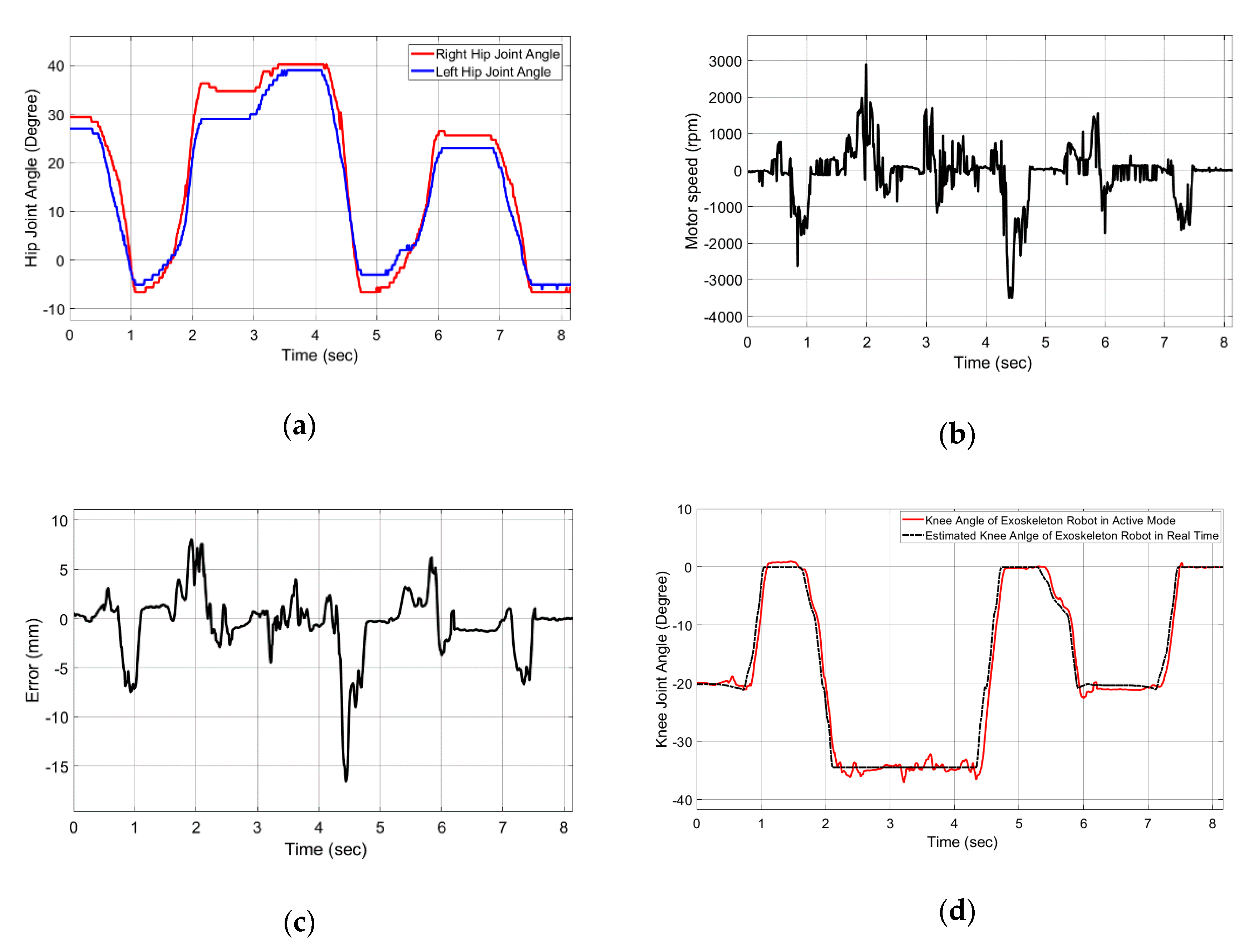
The experimental data of the sit-to-stand motion profile are shown in Figure 12 above. The exoskeleton robot’s hip joint was designed to be passive, and depending on the wearer’s hip joint, it can sit and stand up. Through the experiment, it was confirmed that the control was performed according to the intention of the wearer. In Figure 12a, there was a slight difference in the angle of the two hip joints, but the motion profile was created according to the wearer’s intention, as shown in Figure 12d. The tracking error occurred temporarily in the reverse rotation section of the motor due to the quick response of the controller, as shown in Figure 12c. The speed of the motor matched the size of the error, as shown in Figure 12b.

4. Conclusions

In this study, we proposed a weighted fuzzy logic algorithm using hip joint angles and plantar pressure sensors to control the knee joint angle of the EHA-driven exoskeleton robot. We conducted two experiments using an exoskeleton robot—namely, with and without an actuator in the exoskeleton robot. The first experiment was conducted without an actuator for muscle strength, where only the exoskeleton robot was worn, and walking was performed. The predefined rule bases of the proposed system were fixed, but the knee joint angle was adjusted using the weight adjustment criteria according to the hip joint angle. Through this experiment, we verified that the motion profiles estimated the robot’s joint angle well in real time using the hip joint angles and the pressure sensors. Although the proposed algorithm was designed with 68 predefined rule bases in the fuzzy inference, which did not exactly estimate the knee angle in real time, the motion profiles created from the fuzzy inference estimated the robot’s knee joint angle close to the desired joint angle. In the second experiment, we evaluated whether the proposed algorithm estimated the wearer’s intention well when combined with the EHA system. In the gait experiment, an error temporarily occurred in the swing section, but it was confirmed that the error was reduced. In the sit-to-stance movement experiment, it was confirmed that the knee angle was more stable than in the gait experiment. Due to the misalignment between the exoskeleton and the wearer, the complexity, and the uncertainties, it is difficult to identity a wearer’s intention. Despite these difficulties, through these experiments, the novel method estimated the wearer’s intention in real time and successfully produced a motion profile for the exoskeleton robot knee control. As a result, when workers need to repeatedly transport heavy objects on industrial and construction sites, the exoskeleton robot applying the proposed algorithm can help to increase the worker productivity and to reduce fatigue and the risk of injury.
The proposed method can be programmed for various situations using the fuzzy inference. Although the weights of the proposed system are fixed, the system can be further improved by using criteria that adjust the weights according to the system’s performance. If an improved system is to be used, it can be applied not only to industrial robot requiring power and mobility but, also, to rehabilitation robots requiring precision and stability.

Author Contributions

Conceptualization, formal analysis, methodology, software, validation, and writing—original draft preparation, B.S.; methodology, validation, and writing—review and editing, D.L.; methodology, formal analysis, and writing—review and editing, S.Y.P.; and supervision, project administration, and funding acquisition, Y.S.B. All authors have read and agreed to the published version of the manuscript.

Funding

This research was supported by the Basic Science Research Program grant funded by the National Research Foundation of Korea (NRF) (No. 2017R1A2B4009265).

Conflicts of Interest

The authors declare no conflict of interest.

References

  1. UN Population Division. World Population Ageing 2015, Population Face Sheet. Available online: https://www.un.org/en/development/desa/population/publications/pdf/popfacts/PopFacts_2014-4Rev1.pdf (accessed on 16 September 2020).
  2. Rupal, B.S.; Rafique, S.; Singla, A.; Singla, E.; Isaksson, M.; Virk, G.S. Lower-limb exoskeletons. Int. J. Adv. Robot. Syst. 2017, 14. [Google Scholar] [CrossRef]
  3. Gilbert, K.E.; Callan, P.C. Hardiman I Prototype Project; General Electric Company: Schenectady, NY, USA, 1969. [Google Scholar]
  4. Ghan, J.; Steger, R.; Kazerooni, H. Control and system identification for the Berkeley lower extremity exoskeleton (BLEEX). Adv. Robot. 2006, 20, 989–1014. [Google Scholar] [CrossRef]
  5. Walsh, C.J.; Endo, K.; Herr, H. A quasi-passive leg exoskeleton for load-carrying augmentation. Int. J. Humanoid Robot. 2007, 4, 487–506. [Google Scholar] [CrossRef]
  6. Esquenazi, A.; Talaty, M.; Packel, A.; Saulino, M. The ReWalk Powered Exoskeleton to Restore Ambulatory Function to Individuals with Thoracic-Level Motor-Complete Spinal Cord Injury. Am. J. Phys. Med. Rehabil. 2012, 91, 911–921. [Google Scholar] [CrossRef] [PubMed] [Green Version]
  7. Yamamoto, K.; Hyodo, K.; Ishii, M.; Matsuo, T. Development of Power Assisting Suit for Assisting Nurse Labor. JSME Int. J. Ser. C 2002, 45, 703–711. [Google Scholar] [CrossRef] [Green Version]
  8. Kusuda, Y. In quest of mobility-Honda to develop walking assist devices. Ind. Robot. Int. J. 2009, 36, 537–539. [Google Scholar] [CrossRef]
  9. Song, B.; Lee, D.; Park, S.Y.; Baek, Y.S. Design and Performance of Nonlinear Control for an Electro-Hydraulic Actuator Considering a Wearable Robot. Processes 2019, 7, 389. [Google Scholar] [CrossRef] [Green Version]
  10. Ahn, K.-K.K.; Nam, D.N.C.; Jin, M. Adaptive Backstepping Control of an Electrohydraulic Actuator. IEEE/ASME Trans. Mechatron. 2013, 19, 987–995. [Google Scholar] [CrossRef]
  11. Lee, D.; Song, B.; Park, S.Y.; Baek, Y.S. Development and Control of an Electro-Hydraulic Actuator System for an Exoskeleton Robot. Appl. Sci. 2019, 9, 4295. [Google Scholar] [CrossRef] [Green Version]
  12. Michael, P.; Greene, B.S. Four Bar Linkage Knee Analysis. Orthot. Prosthet. 1983, 37, 15–24. [Google Scholar]
  13. Collo, A.; Bonnet, V.; Venture, G. A quasi-passive lower limb exoskeleton for partial body weight support. In Proceedings of the 6th IEEE International Conference on Biomedical Robotics and Biomechatronics (BioRob), Singapore, 26–29 June 2016; Institute of Electrical and Electronics Engineers (IEEE): Singapore, 2016; pp. 643–648. [Google Scholar]
  14. Perry, J.C.; Rosen, J.; Burns, S. Upper-Limb Powered Exoskeleton Design. IEEE/ASME Trans. Mechatron. 2007, 12, 408–417. [Google Scholar] [CrossRef]
  15. Reaz, M.B.I.; Hussain, M.S.; Mohd-Yasin, F.; Raez, M. Techniques of EMG signal analysis: Detection, processing, classification and applications. Boil. Proced. Online 2006, 8, 11–35. [Google Scholar] [CrossRef] [PubMed] [Green Version]
  16. Long, Y.; Du, Z.-J.; Wang, W.-D.; Dong, W. Human motion intent learning based motion assistance control for a wearable exoskeleton. Robot. Comput. Integr. Manuf. 2018, 49, 317–327. [Google Scholar] [CrossRef]
  17. Ding, S.; Ouyang, X.; Li, Z.; Yang, H. Proportion-based fuzzy gait phase detection using the smart insole. Sens. Actuators A Phys. 2018, 284, 96–102. [Google Scholar] [CrossRef]
  18. Huo, W.; Mohammed, S.; Amirat, Y.; Kong, K. Fast Gait Mode Detection and Assistive Torque Control of an Exoskeletal Robotic Orthosis for Walking Assistance. IEEE Trans. Robot. 2018, 34, 1–18. [Google Scholar] [CrossRef]
  19. Shim, M.; Han, J.I.; Choi, H.S.; Ha, S.M.; Kim, J.-H.; Baek, Y.S. Terrain Feature Estimation Method for a Lower Limb Exoskeleton Using Kinematic Analysis and Center of Pressure. Sensors 2019, 19, 4418. [Google Scholar] [CrossRef] [PubMed] [Green Version]
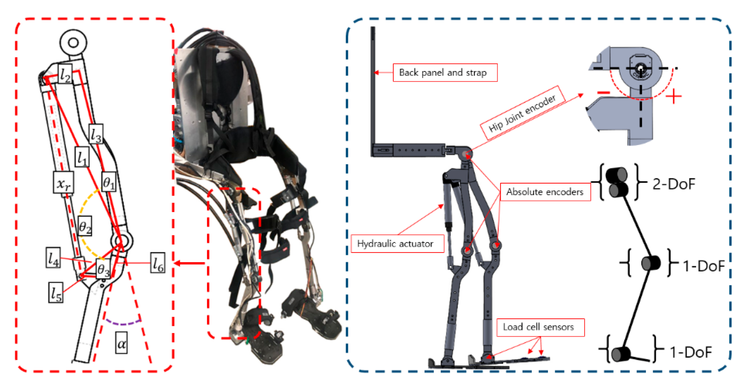
Figure 1. Design of an exoskeleton robot with an electro-hydraulic actuator (EHA) system. DoF: degrees of freedom.
Applsci 10 06852 g001
Figure 2. Stance and swing phases in the gait cycle.
Applsci 10 06852 g002
Figure 3. Displacement of the cylinder rod x r during a gait cycle.
Applsci 10 06852 g003
Figure 4. Schematic diagram of the overall fuzzy logic algorithm.
Applsci 10 06852 g004
Figure 5. Input membership function of the fuzzy set: Hip joint angles. N, negative; ZR, zero; P, positive; PS, positive small; PM, positive medium; and PL, positive large.
Applsci 10 06852 g005
Figure 6. Simulation results of the proposed algorithm for estimating the knee joint angle: (a) the summed plantar pressure sensors for distinguishing the gait phase, (b) the crisp inputs of the hip joint angles, (c) the comparison of the estimated robot knee and the actual robot knee, and (d) the measurement error between the estimated output and the actual output.
Applsci 10 06852 g006
Figure 7. Output membership function of the fuzzy set: cylinder rod stroke.
Applsci 10 06852 g007
Figure 8. System block diagram of the estimated algorithm combined with the EHA [9].
Applsci 10 06852 g008
Figure 9. Schematic diagram of the experimental set-up for the exoskeleton system. ADC, analog-to-digital converter; CAN, controller area network; LVDT, linear variable differential transformer; MCU, main controller unit; SPI, serial peripheral interface; and MFC, Microsoft foundation class.
Applsci 10 06852 g009
Figure 10. Experimental results of the proposed algorithm for estimating the knee joint angle: (a) the crisp inputs of the hip joint angles, (b) the plantar pressure sensors for distinguishing the gait phase, (c,d) the fuzzy inputs and outputs, respectively, between 1.7 and 2.7 s, and (e) the results of the knee joint angle x r and the estimated knee joint angle x ^ r .
Applsci 10 06852 g010
Figure 11. Exoskeleton robot in the walking experiment on level ground: (a) the change of the hip joint angles, (b) the sum of the plantar pressure sensors, (c) the motor speed, (d) the tracking error, and (e) a comparison of the actual and the estimated knee joint angles of the exoskeleton robot.
Applsci 10 06852 g011
Figure 12. The sit-to-stand movement experiment: (a) the change in the hip joint angles, (b) the motor speed, (c) tracking error, and (d) a comparison of the actual and the estimated knee joint angles of the exoskeleton robot.
Applsci 10 06852 g012
Table 1. Fuzzy rules set for the swing phase.
Input2
RNRZRRPRPSRPMRPL
Input1LNVLLMHVHNA
LZRLVLLMHVH
LPMLVLLMH
LPSHMLVLLM
LPMVHHMLVLL
LPLNAVHHMLVL
For the inputs: LN, left negative; LZR, left zero; LP, left positive; LPS, left positive small; LPM, left positive medium; and LPL, left positive large (similarly for the right (R) inputs). For the outputs: VL, very low; L, low; M, medium; H, high; VH, very high; and NA, not applicable.
Table 2. Fuzzy rules set for the stance phase.
Input2
RNRZRRPRPSRPMRPL
Input1LNVHVHVHHVHNA
LZRVHVHHMHVH
LPVHHHMMH
LPSHMMMMM
LPMVHHMMMM
LPLNAVHHMMM