1. Introduction
Detailed mechanical characterizations of lattice structures may sometimes conduce to heavy, costly, and actually impracticable models. As valid substitutes, homogeneous structural models, very often and suitably, serve to address the mechanical behavior of lattices, when a large scale (macro) point of view is pursued. In fact, homogenization procedures lead to replace the original structure by a continuum model, which equivalently represents that and, concurrently, is easier to be analyzed [
1]. For instance, structural mechanics of pantographic platelike can be conveniently addressed by equivalent macro-mechanical models, as in [
2], where anisotropy aspects are transferred from the micro- to the macro-representation, and a consequent challenging onset of boundary layers is triggered. As another common example, beamlike structures (see [
3]) are used as equivalent models to describe tall buildings, where the periodicity of the lattice is provided by the uniform repetition of the modular cell, which is the single story, in the vertical direction. In this context, the identification of the constitutive parameters of a homogeneous beamlike is described in [
4], which leads to perform buckling analysis [
5,
6] as well as to propose innovative analytical-numerical tools to address mechanics [
7]. Improvements on the same macro-mechanical model, voted to take into account peculiar and substantial features of the micro-mechanical model, and specifically related to the slab elastic deformation, are given in [
8]. Both linear and nonlinear dynamics of the aforementioned beamlike model are also addressed in [
9] and [
10], respectively, highlighting distinctive behavior related to the special organization of the modal properties. Such homogeneous models are also used to consider aeroelastic phenomena in tall towers [
11,
12,
13,
14,
15], even in the case of linked and collaborating pairs of buildings [
16,
17].
Still dealing with beamlike structures, the Generalized Beam Theory (GBT, [
18]) provides a compelling method to describe the mechanics of thin-walled members by means of suitable homogeneous models. There, cross-section analysis and member analysis represent the two main steps: specifically about the first one, which consists of the crucial choice of a reduced basis to represent the deformation of the cross-section of the thin-walled beam, the use of a finite number of dynamic normal modes of a corresponding unconstrained frame, in the shape of the cross-section itself, is proposed in [
19]. Then, in [
20,
21], further enrichment of the basis, introduced in order to address the behavior in case of large displacements as well as in specific situations, completes the definition of the so-called Dynamic GBT (referred to as GBT-D). Under the same common thread, beams realized by composite materials are able to perform cross-section change in shapes and are consistently substituted by homogeneous models in [
22,
23,
24].
In the last decade, many efforts have been spent to address the mechanical behavior of masonry structures by multiscale approaches [
25,
26], as well, i.e., making use of homogeneous and suitable replacements of the original structures. Specifically, different homogenization techniques are reviewed in [
27], where the focus is also given to some promising micromechanical models. A simple homogenization procedure for the description of in-plane elastic deformation of masonry blocks by means of manageable rheological models is proposed in [
28]. A nonlinear homogeneous model to describe in-plane behavior of masonry walls is proposed in [
29], where a novel constitutive law for mortar joints plays a crucial role in the definition of the procedure. In [
30], it is shown how distinct equivalent continuum models, namely a micropolar Cosserat continuum and a nonlocal Cauchy model, may be derived from the proposed homogenization technique.
Actually, due to the complex behavior (see [
31] for a comprehensive review) and to the difficulties of consistently fulfilling detailed modeling of masonry structures, examples of simplified models are proposed in the literature. For instance, the assessment of dissipation and deformation capacities of frame-masonry shear-wall systems in post-cracking regime is carried out in [
32,
33], where continuum damage models for masonry are used.
Clearly, especially when dealing with historical masonry structures, where irregular textures are often present [
34,
35], theoretical prediction models require validation. This important step can smoothly be accomplished comparing the predictions to the outcomes of experimental test [
36,
37,
38,
39], and possibly re-calibrating the model parameters, accordingly.
This paper draws inspiration from a case study, constituted by a vast Italian building, realized with historical masonry (about the 18th century), which has been subjected to several (and mostly unknown) restoration works during its long life. The principal aim is to investigate the dynamic behavior of the whole building, in order to: (a) evaluate the existence of local mechanisms and (b) possibly identify any global behaviors. The complexity and extension of the building prevent the possibility of realizing a comprehensive fine model, in the framework of the Finite Element Method. Thus, an innovative approach is proposed, finalized to define a simplified model, which is composed of homogenized orthotropic plates, and which makes use, in its development, of Timoskenko and pure shear beam models, as well. The homogenization procedure is realized as a combination of pure analytical modeling and numerical finer modeling of building portions. The results are validated comparing the outcomes of both fine and homogeneous models with those provided by experimental dynamic identifications, which, due to the large extension of the building, are actually carried out only on some of its portions.
The paper is organized as follows. In
Section 2, the case study is described. In
Section 3, three fine finite element models of a building portion, in which different structural elements are included, are developed. In
Section 4, three homogenized models of the same building portion are defined. In
Section 5 and
Section 6, the homogenized model parameters are identified. In
Section 7, the homogenized model of the whole building is defined. In
Section 8, experimental dynamic identifications are described and the modal analyses of all defined models are performed and the models validated. Finally, in
Section 9, the main findings of the work are summarized. Two appendices are presented at the end of this paper.
2. The Case Study
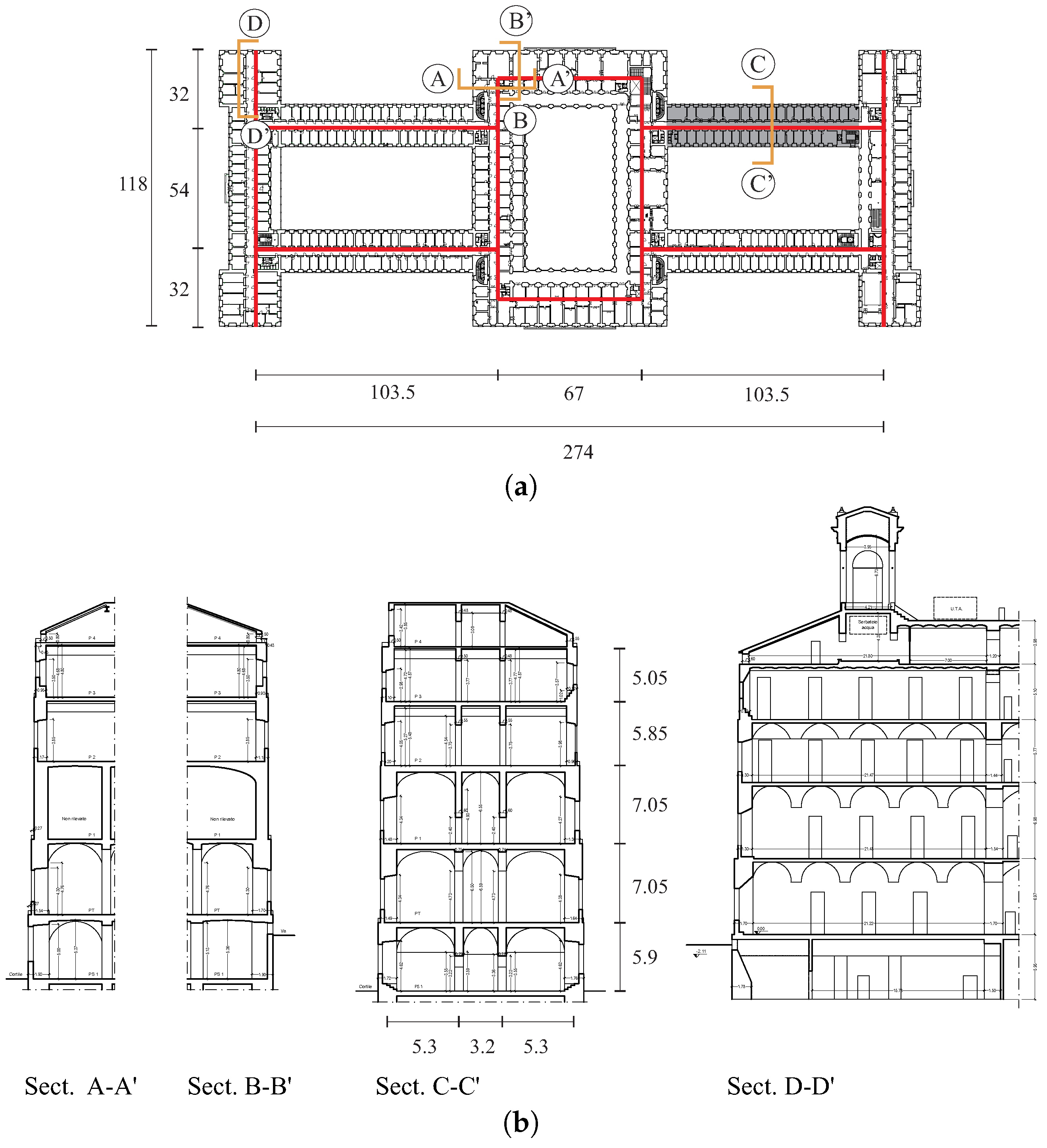
The case study is an important ancient masonry building in Italy (headquarters of the Italian Ministry of Economy and Finance—MEF, in Rome (Italy)). The building is located in a large rectangular area, with sides 300 m and 120 m. The structure is a closed block with three internal courtyards, one main central and the other two lateral, arranged symmetrically with respect to the central transverse axis of the building. The covered surface is about 19,000 m, while the area on which the building stands is equal to 36,000 m. The building is constituted by six levels, including a basement, a raised ground floor, four floors above, the latter of which is partly covered by a practicable slab. The average height is approximately 33 m overall.
Basically, the building can be thought as consisting of four transverse and six longitudinal arms with a width between 18 and 22 m and a variable length between 70 and 85 m. At the corners of the building, there are also four small towers with turrets placed at the top. Each arm consists of a package of four parallel, longitudinal walls, two external (street side and courtyard side) and two internal (delimiting a corridor), connected by the horizontal elements and by transverse localized and distributed walls.
Moreover, due to the extension of the building: (i) different types of masonry (mainly tuff blocks and solid bricks and mortar) are present; (ii) the slabs are of various nature (as beams and vaults, vaults and arches, beams and flooring block, cement); (iii) in some cases, the presence of horizontal systems (made with steel plates or rods) for chaining the walls has been found.
Plan and sections of the described building are shown in
Figure 1.
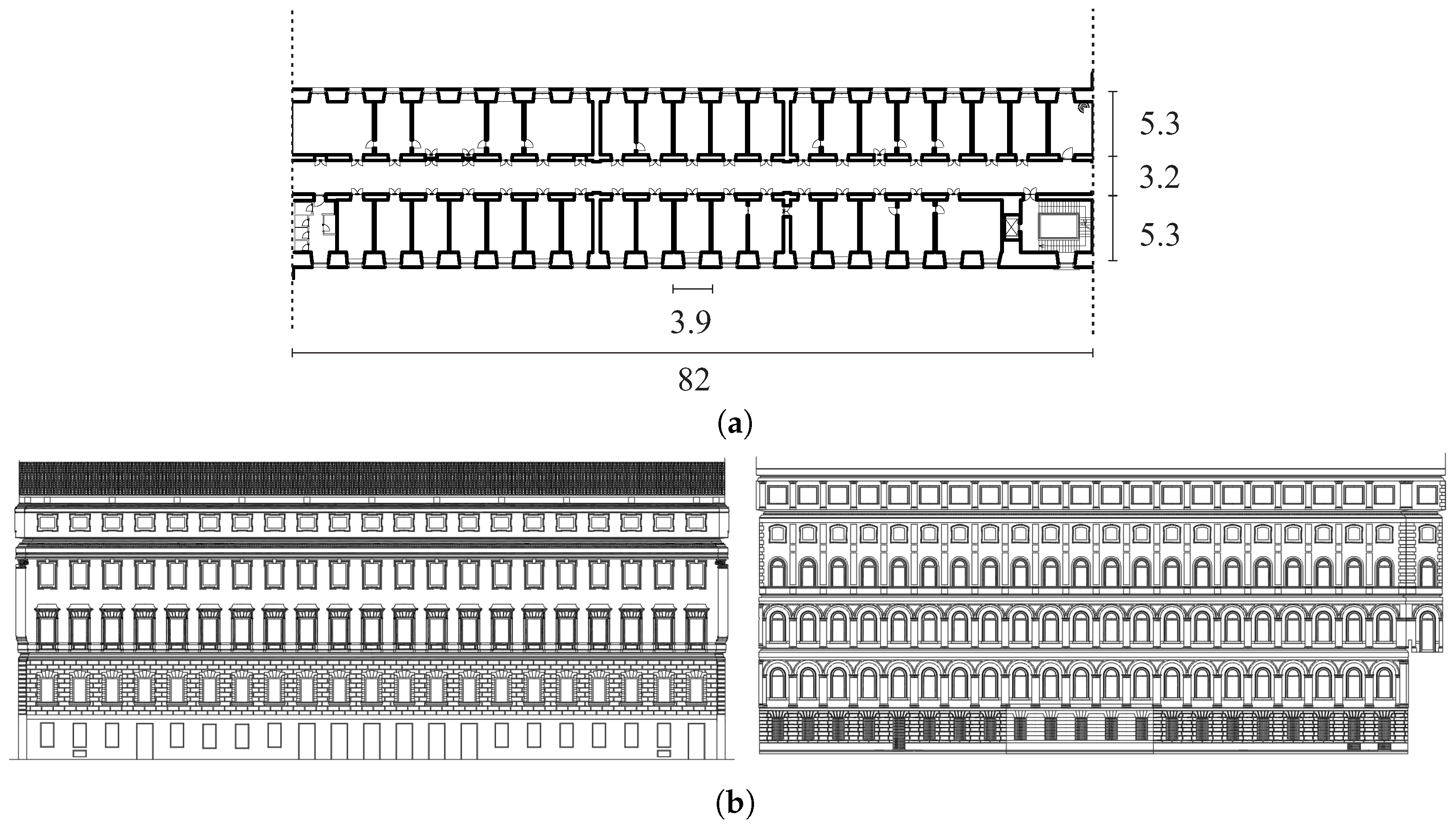
For reasons that will be clear below, particular attention is addressed on the longitudinal arm highlighted in
Figure 1a. A more detailed plan of the this latter, together with the perspectives of the two external facades, is shown in
Figure 2. Concerning this building portion:
the longitudinal walls taper from the bottom upwards with thicknesses ranging from to m;
the interstory heights are between 4 and 7 m;
the slabs consist of cross vaults (with fixed geometry and an estimated thickness of about 10 cm) at the first three levels, and of steel beams with I sections (normal NP profile ), distributed with inter-axis of m, at the last two levels;
couples of transverse walls, both localized (thickness about 70 cm) and of uniformly distributed (thickness about 15 cm) with an inter-axis of m, stiffens the structure;
the masonry is assumed everywhere of solid bricks and mortar;
the presence of horizontal systems for chaining the walls is assumed at the first three levels.
3. Fine Model of a Building Portion
First, a
fine finite element model of a building portion is developed to study some structural mechanisms and, then, to calibrate some parameters of the homogenized model. The studied portion consists of the long longitudinal arm described in the case study, believed to be the most vulnerable seismically portion. Moreover, the long longitudinal arms are very similar to each other and the modest local differences can be considered such as not to significantly change the dynamic behavior. All the FEM models are implemented in the commercial software SAP 2000 [
40].
The structural elements composing the studied arm are modeled as follows:
The longitudinal and transverse walls and the vaults are modeled by homogeneous isotropic shell elements, having both a membrane and flexural behavior. Any element is a Cauchy continuum body in plane stress, defined in a 2D space, and obeys a hyperelastic isotropic linear law according to the Young modulus and the Poisson factor of the block masonry.
The slab beams are modeled by one-dimensional Timoshenko beam elements, axially, bending and shearing deformable. They obey to a hyperelastic isotropic linear law according the Young modulus and the Poisson factor of the steel.
An equivalent averaged mass density kg/m (1.6 times that of the masonry) is assigned to the only longitudinal shell elements; all the other elements are mass-free. The equivalent mass is obtained by allocating the total mass (deriving by the own weight of the vertical elements, according the masonry mass density 1900 kg/m, and the slab-bearing load equal to 11–15 kN/m) to the only longitudinal walls.
The geometric and mechanical characteristics of the vertical and horizontal elements have been assigned on the basis of information obtained from knowledge campaigns. Details about the geometry can be found in
Section 2. The soil–structure interaction was not taken into account, so that external fixed constraints were applied to all the base nodes. The interaction with the other building arms is modeled by hinge constraints applied to the nodes of the vertical sides of each facade.
In order to investigate the influence of the localized and distributed transverse walls, three finite element models are defined:
the Longitudinal Wall (LW) fine model, composed only by a package of four parallel longitudinal walls and horizontal slabs;
the Longitudinal and Transverse Wall (LTW) fine model, composed by a package of four parallel longitudinal walls, horizontal slabs, and transverse distributed walls;
the Stiffened Longitudinal and Transverse Wall (SLTW) fine model, composed by package of four parallel longitudinal walls, horizontal slabs; and distributed and localized transverse walls.
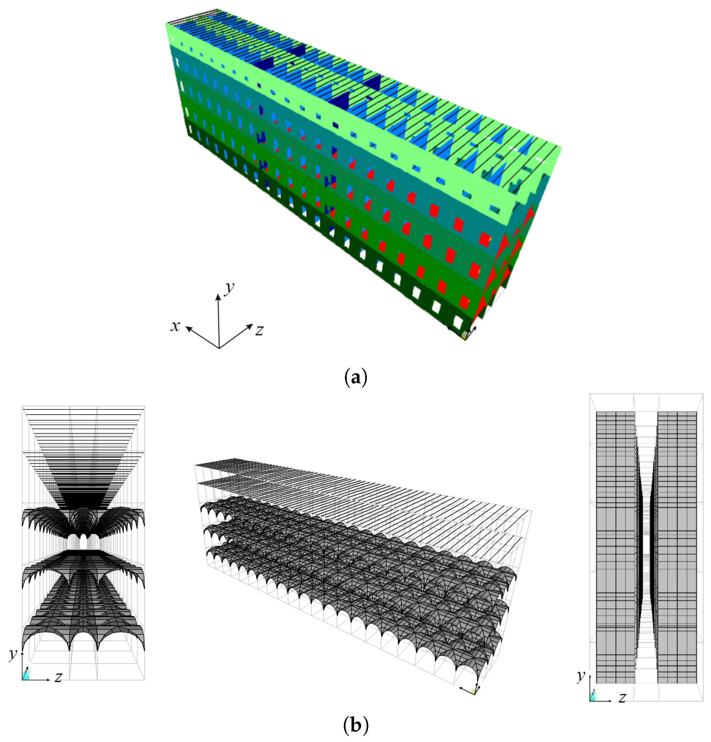
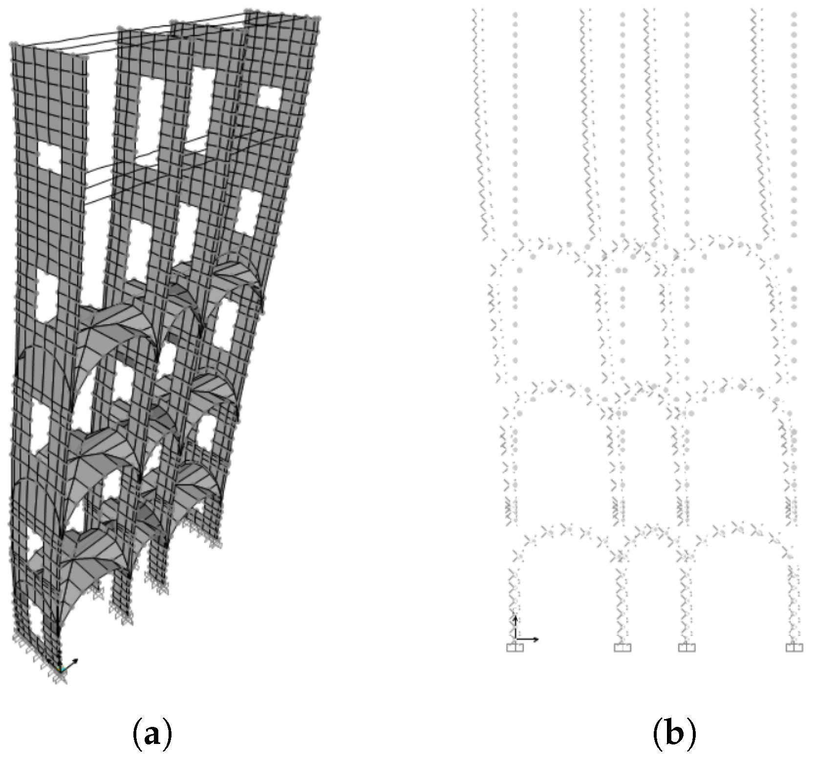
In
Figure 3a, a perspective view of the SLTW finite element model, made up of 39,353 nodes and 40,183 elements, is shown. Different colors are used to distinguish different thicknesses of the shell elements, modeling: The longitudinal walls, in green scale, according the wall tapering; the vaults in red; the localized and distributed transverse walls, respectively, in dark and light blue. The model includes all the levels, with the exception of the last one, considered only as mass.
Figure 3b shows some details about slabs and transverse walls.
4. Homogenized Model of a Building Portion
Here, the homogenized model of the longitudinal arm of the building, consisting of a package of four parallel longitudinal walls, connected transversely by horizontal and vertical elements, is defined. The following assumptions are considered, as a reasonable consequence of the features of the structure:
in membrane behavior, the longitudinal walls always undergo the same extensional and shear strain in the two orthogonal directions;
the slabs are infinitely rigid in their plane, so that the four longitudinal walls actually work in parallel;
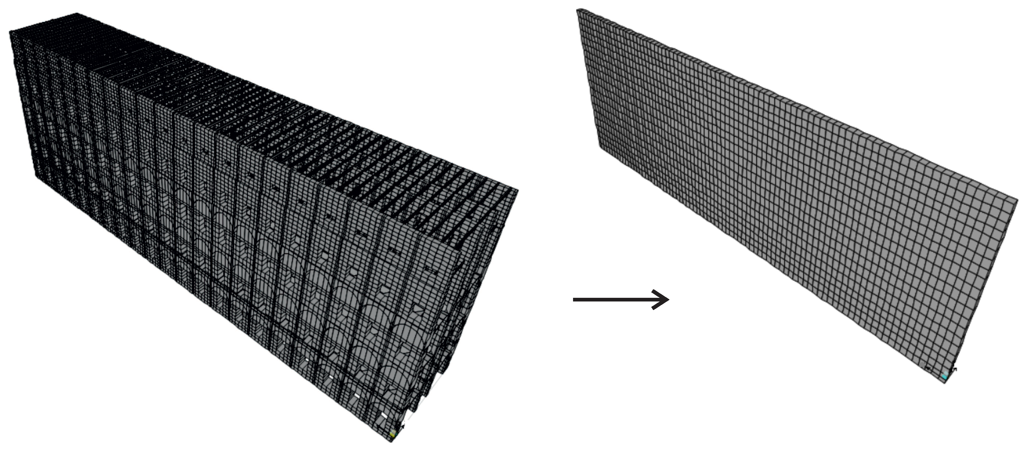
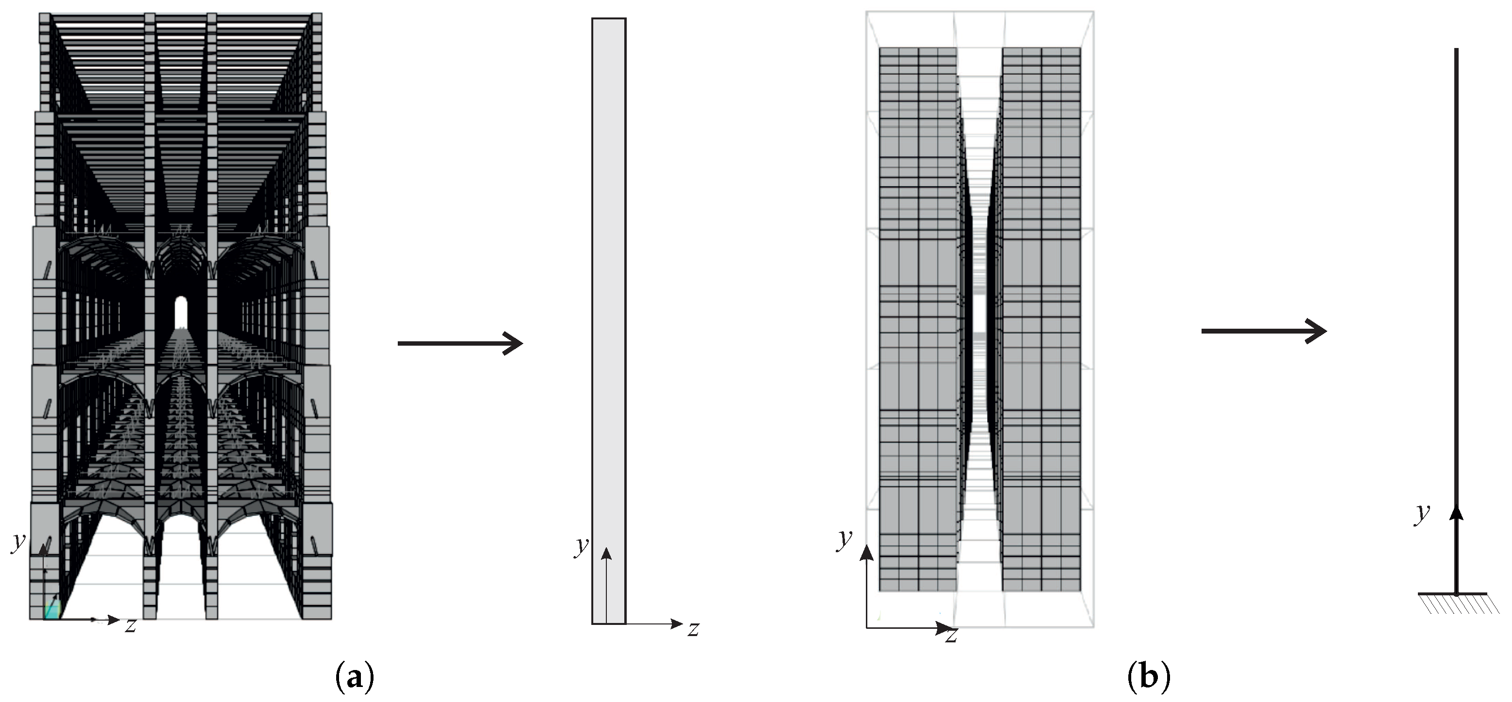
The idea is to substitute an ‘equivalent’ homogeneous plate for the fine model of the arm, having it unitary thickness, the same in plane trace of the block middle line, as well as corresponding stiffness and mass. The plate is fixed at the base and laterally hinged (see the homogenization scheme in
Figure 4).
In particular, for each of the fine models described in
Section 3, a corresponding homogenized model is defined:
The equivalent plates are orthotropic Mindlin–Reissner plates [
41], having the following elastic constitutive laws in the decoupled form:
where:
are the bending and twist moments; the shear forces; the membrane forces;
are the bending and twist curvature, with w the orthogonal displacement of the plate; are the out of plane sliding; the membrane strains (unit extensions and shear sliding ).
are the bending and twist stiffness; the out-of-plane shear stiffness; the membrane stiffness.
Note that, contrary to standard constitutive equations constructed by homogenization, as shown e.g., in [
42], here the off-diagonal terms are neglected, by assuming the Poisson factor to be zero. This assumption: (i) is reasonable in the context of the approximations of the problem, in which the Poisson effect plays a certainly minor role; and (ii) remarkably simplifies the homogenization procedures, by allowing to identify separately the plate elastic constants relative to different directions.
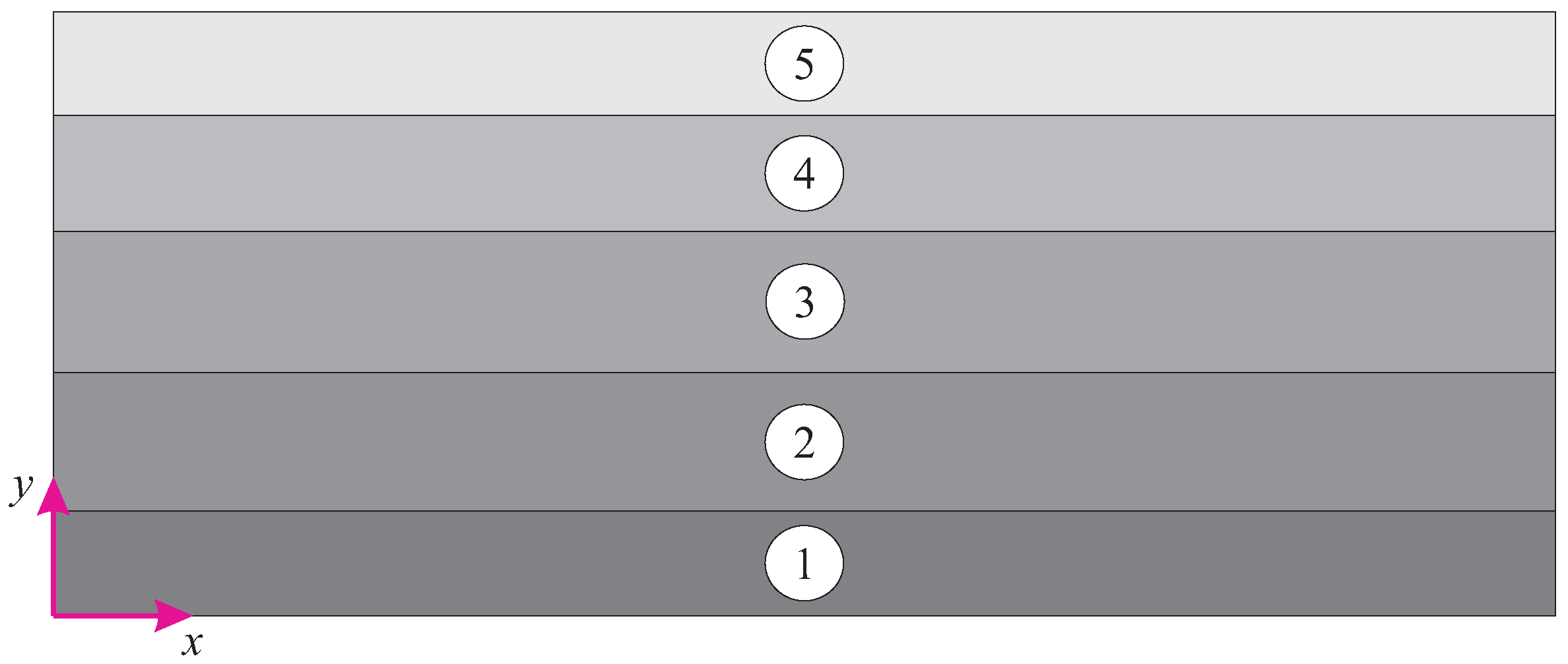
The identification of the equivalent in-plane and out-of-plane elastic constants represents an important goal of the work. In particular, since the geometry varies in height (due to wall tapering and different kinds of slabs), each homogenized model is actually composed by five equivalent plates, having the corresponding interstory height, numbered from bottom to top as in
Figure 6. Each of the five plates has to be identified. The problem is stated as follows: the geometry of the assembly being known as well as the elastic properties of the elements, determining the elastic stiffness coefficients
of each equivalent plate. This is made, in part, from a pure analytical modeling and, in part, through numerical finer modeling.
Concerning the equivalent mass of the homogeneous plates, an average mass density kg/m is determined by dividing the total load of the longitudinal arm for the plate volume. All the other elements are considered mass-free.
5. LW Homogenized Model Identification
Preliminary analyses, carried out on the LW fine model, showed that the out-of-plane behavior is substantially equivalent to that of a pure shear plate. Therefore, the equivalent bending and twist stiffness coefficients are assumed , and the identification procedure is limited to determine the six elastic membrane and shear stiffness coefficients , for each of the five equivalent plates. Different approaches are used:
the in-plane behavior is characterized by energy equivalences on the basis of exclusively analytical models;
the out-of-plane behavior is characterized by displacement equivalences on the basis of fine numerical models: This more involved approach is due to the physics of the problem where mainly during out-of-plane displacements, interaction between vertical and horizontal structures occurs.
5.1. In-Plane (Membrane) Behavior
Assuming each wall of the fine model to behave as a homogeneous and isotropic Cauchy continuum, of elastic Young modulus and Poisson factor , respectively, the membrane elastic constants ,, are determined for the equivalent plates at the different stories as follows.
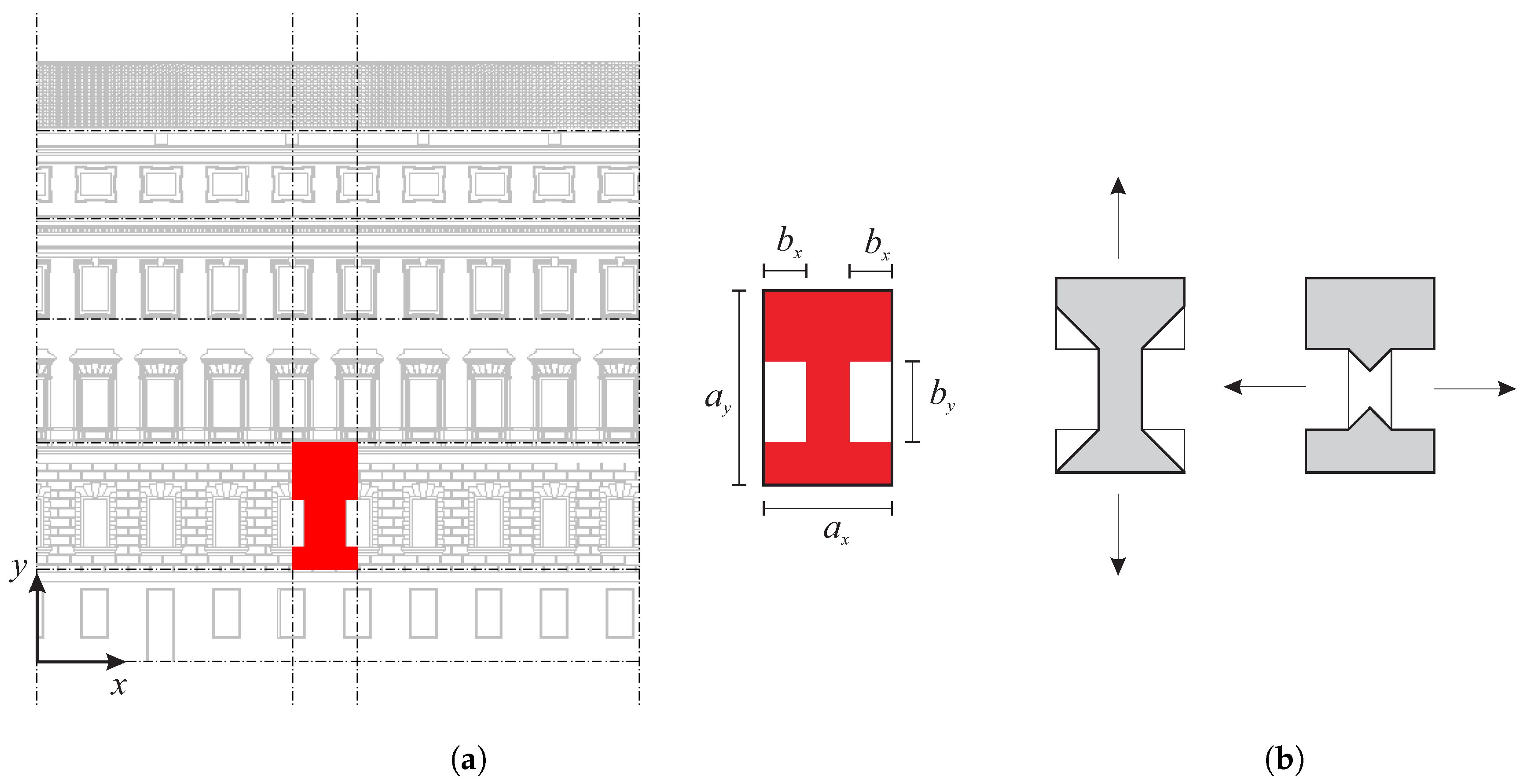
On any of the stories, the longitudinal walls are characterized by almost identical windows, periodically repeated along the length. Therefore, it is easy to identify Representative Volume Elements (RVE), whose assembly reproduces the walls: A rectangular cell of dimensions
, where
is the center distance of the windows,
the interstory height,
x and
y the horizontal and vertical directions, respectively, is used as RVE; see details in
Figure 7a. In each of the four longitudinal wall, the rectangle cell circumscribes a I region, centered on the cell and derived by the intersection between a male wall and part of two horizontal bands. The four I regions are distinguished by the different wall thickness
(with
) and by different void dimensions that are
in the two external facades and
in the two internal facades; see
Table 1. Note that, whereas the dimensions along
x are constant, those along
y vary.
The identification of the membrane elastic stiffness coefficients of each plate is made by equating the strain energy of the four I cells and of the equivalent rectangular cell, of dimensions
and unitary out-of-plane thickness, once the same in-plane strain is applied, assumed constant on the cell domain. Longitudinal strain along
x- and
y-directions are applied to determine the extensional elastic coefficients:
and shear strain is applied to determine the membrane shear stiffness coefficient:
where
and
. It is worth noticing that these identified coefficients are proportional to the full-void difference of the cell, namely:
As a further comment to get Equation (
2), the regions at almost zero-strain (according the real strain distributions) are subtracted to the domain of the I region, as shown in
Figure 7b.
Validation of the identification procedure comes from good agreement in comparing the outcomes of finite element models, when both the fine and homogeneous structures are subjected to the same in-plane solicitations. The numerical results are reported in
Table 2.
5.2. Out-of-Plane (Shear) Behavior
The identification of out-of-plane behavior implies a higher complexity due to the influence of the collaborating slabs. Therefore, to this aim, the LW fine finite element model described in
Section 3, under suitable load and constraint conditions, is used. Here, the geometry of the assembly being known as well as the elastic properties of the elements, the out-of-plane shear elastic constants (
,
) of each homogenized plate are determined as follows.
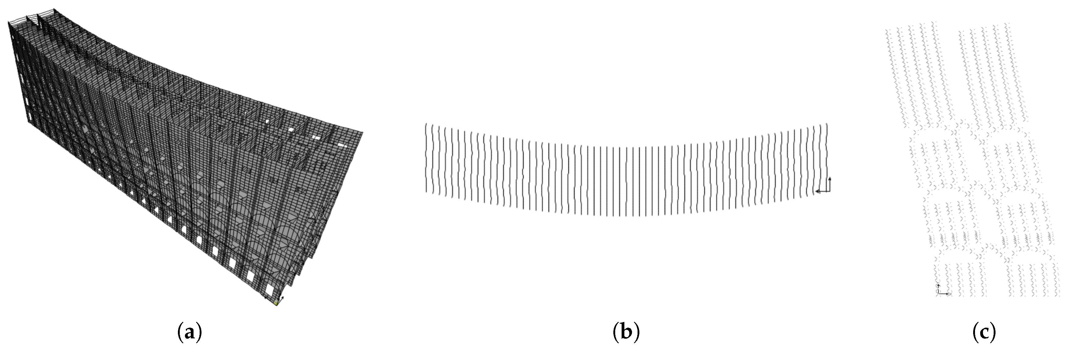
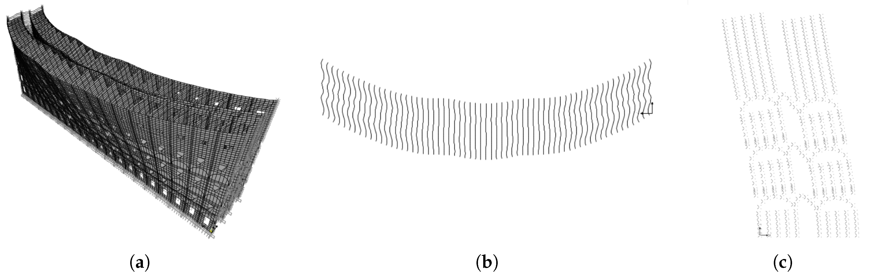
First, coefficient
is identified. To this aim, the LW fine model, released to the base (but still hinged at the sides) and subjected to a horizontal, uniformly distributed load of intensity
N/m
on the surface of the most external facade, is analyzed. The deformed configuration of the fine model is shown in
Figure 8 in (a) the 3D space and (b) the
plane. It is observed that (a) the out-of-plane deformation is strongly influenced by the stiffness difference along
y and (b) the slab beams rigidly move forward, as the cross-sections of a pure shear beam fixed at the ends.
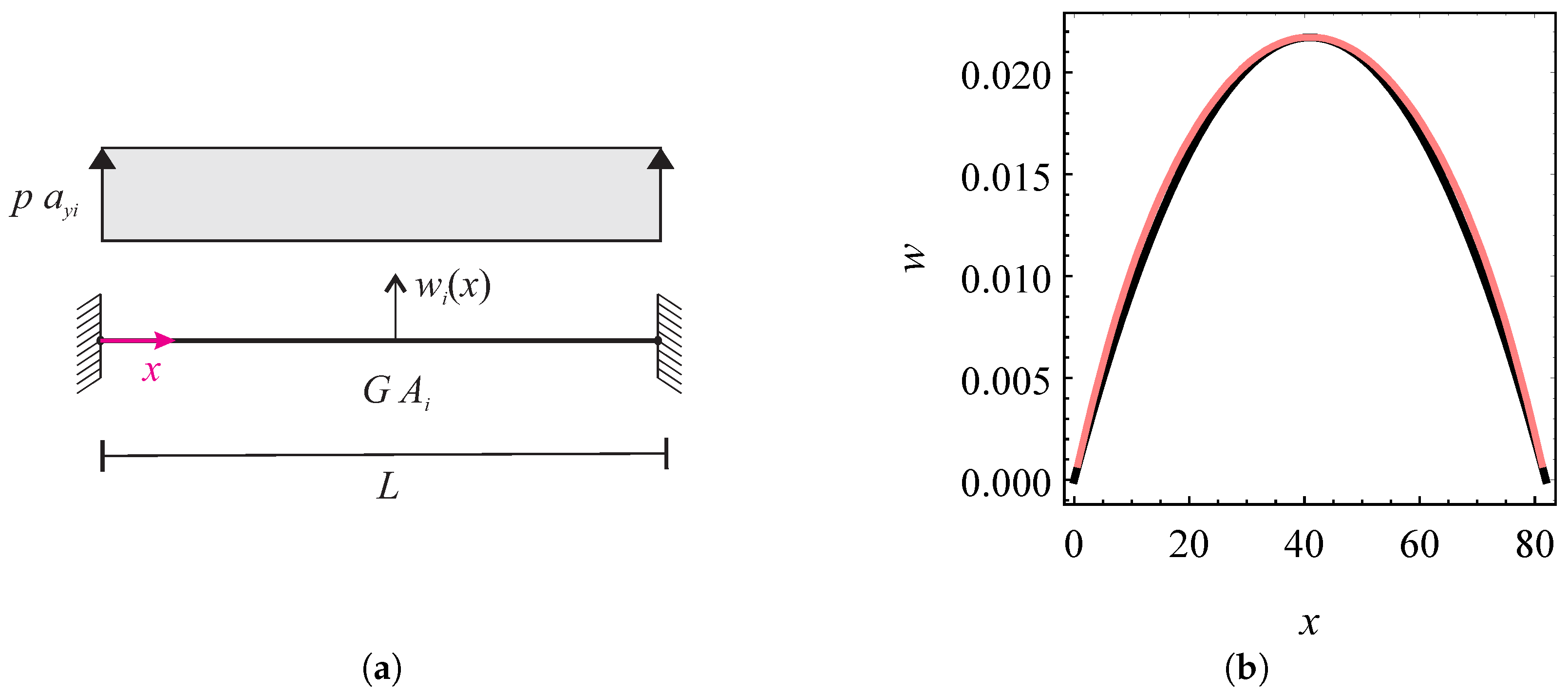
Therefore, the idea is to consider five equivalent pure shear beams, i.e., one for each story, with the axis-line along
x, and calibrate the relevant stiffness coefficients
(for
). The shear beams have a length of
m, i.e., the arm length, are fixed at the ends and are subjected to a uniform load
, with
the interstory height (
Table 1); see the scheme in
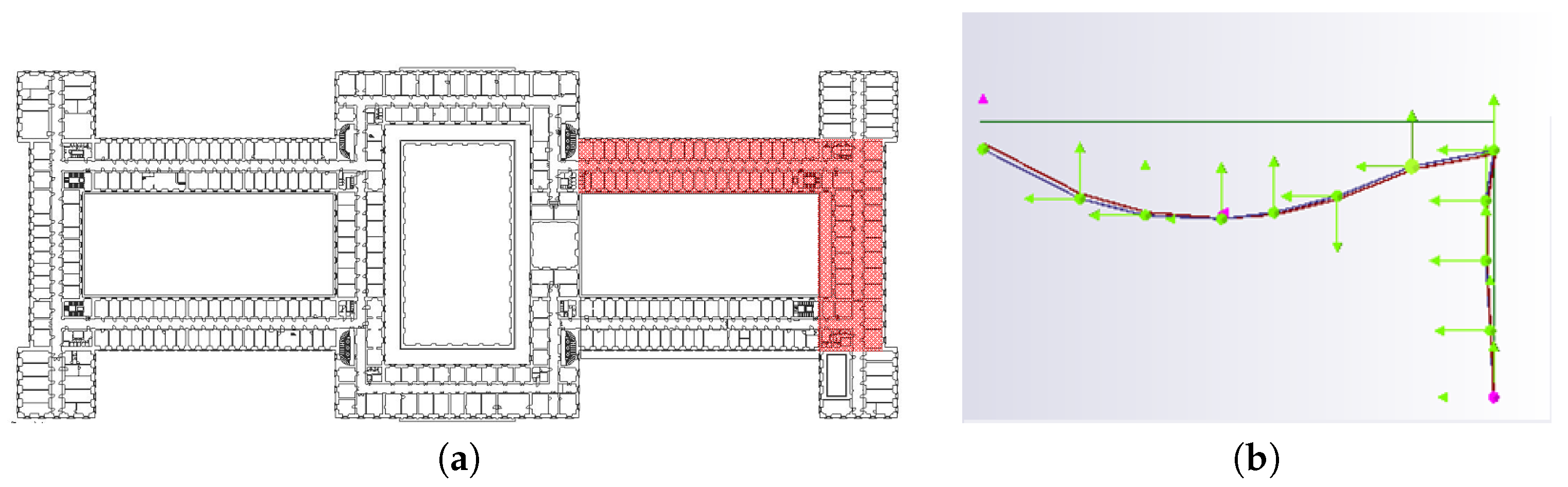
Figure 9a. The identification is made by a displacement equivalence between numerical and analytical models: The out-of-plane displacements of the fine model, evaluated at
and at half height of each interstory, are equated to the mid-span displacement of the equivalent shear beam, namely
, which come from the analytical solving of the relevant differential boundary value problem:
The unknown stiffness coefficient
is thus obtained and, from them, the equivalent plate coefficient comes as
; numerical values are in
Table 2. In
Figure 9b, a comparison between the equivalent beam (
) and fine model deformed configurations in the
plane is shown, and a very good agreement is observed.
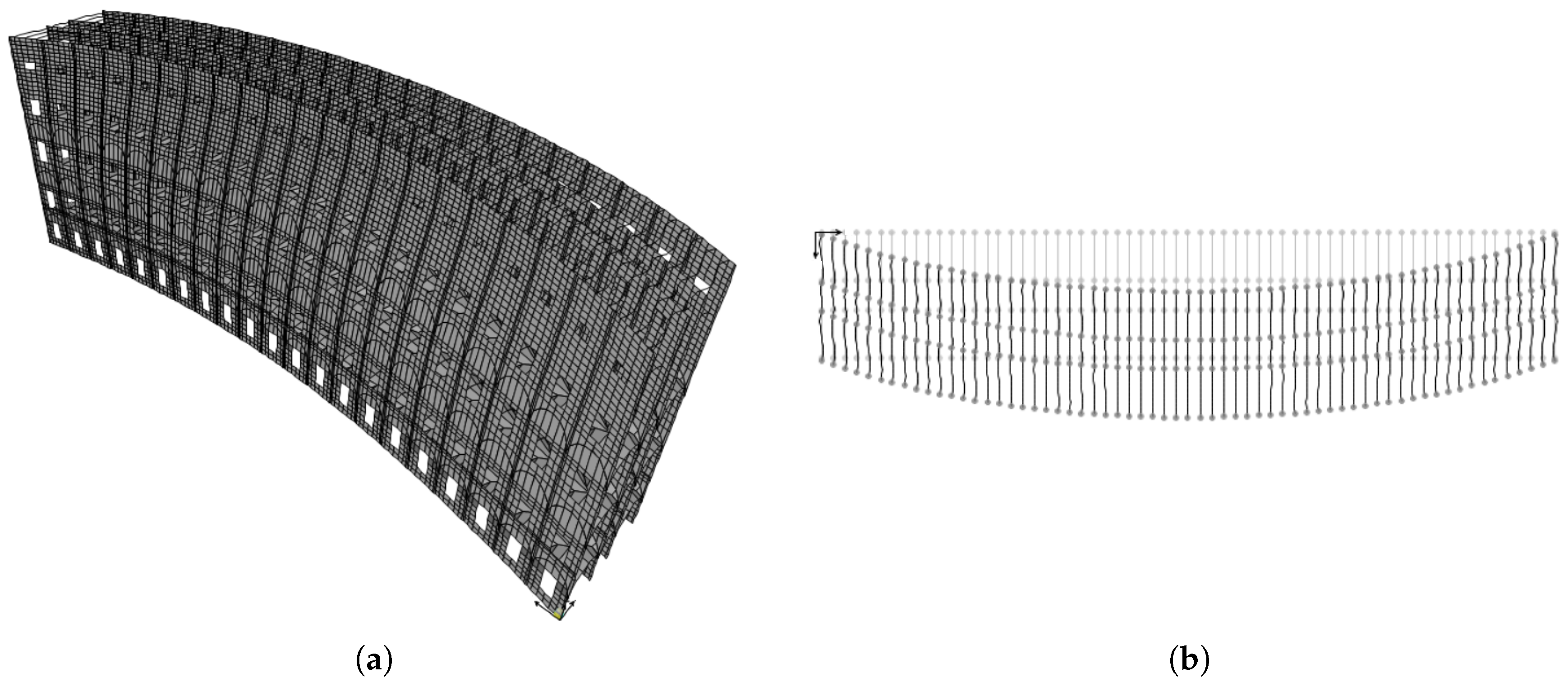
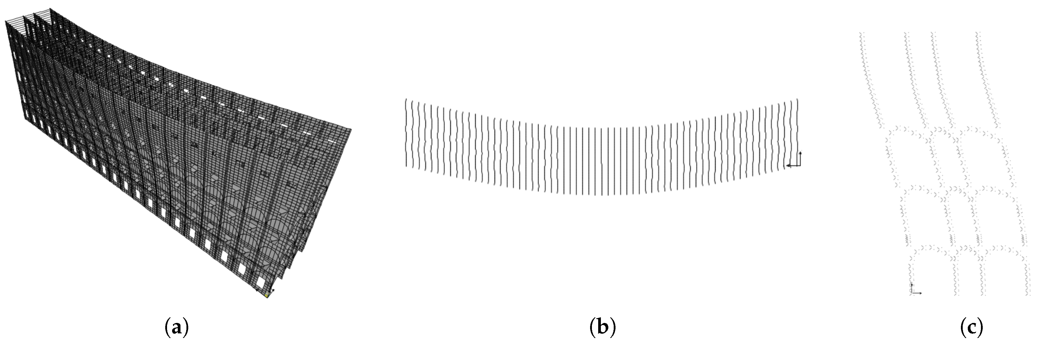
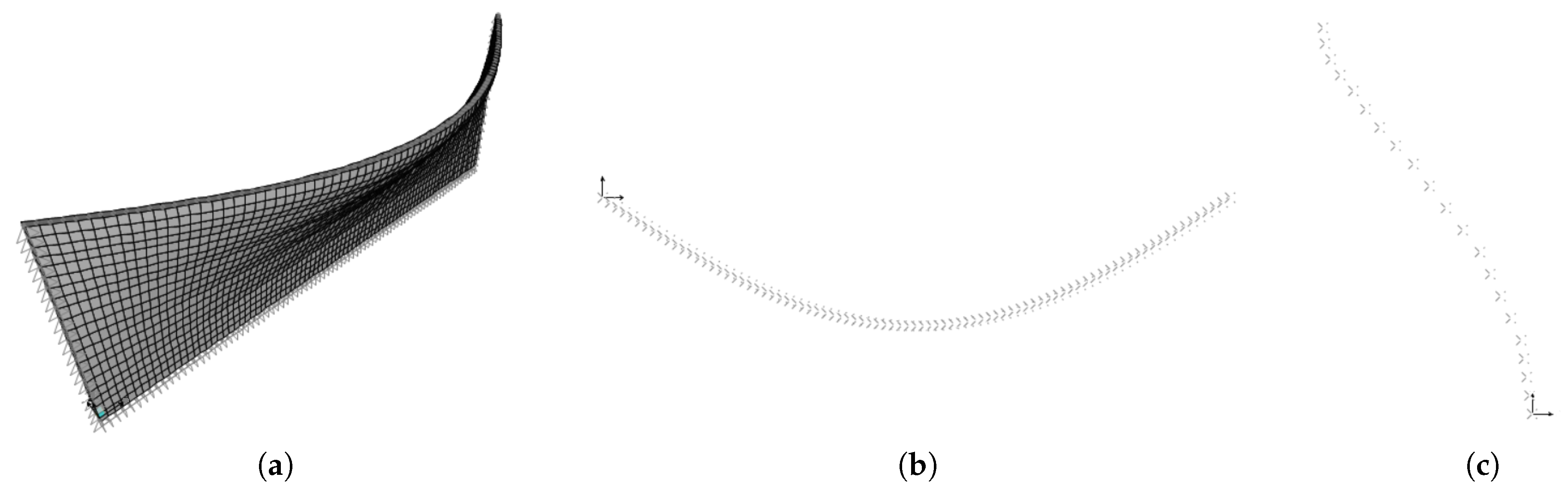
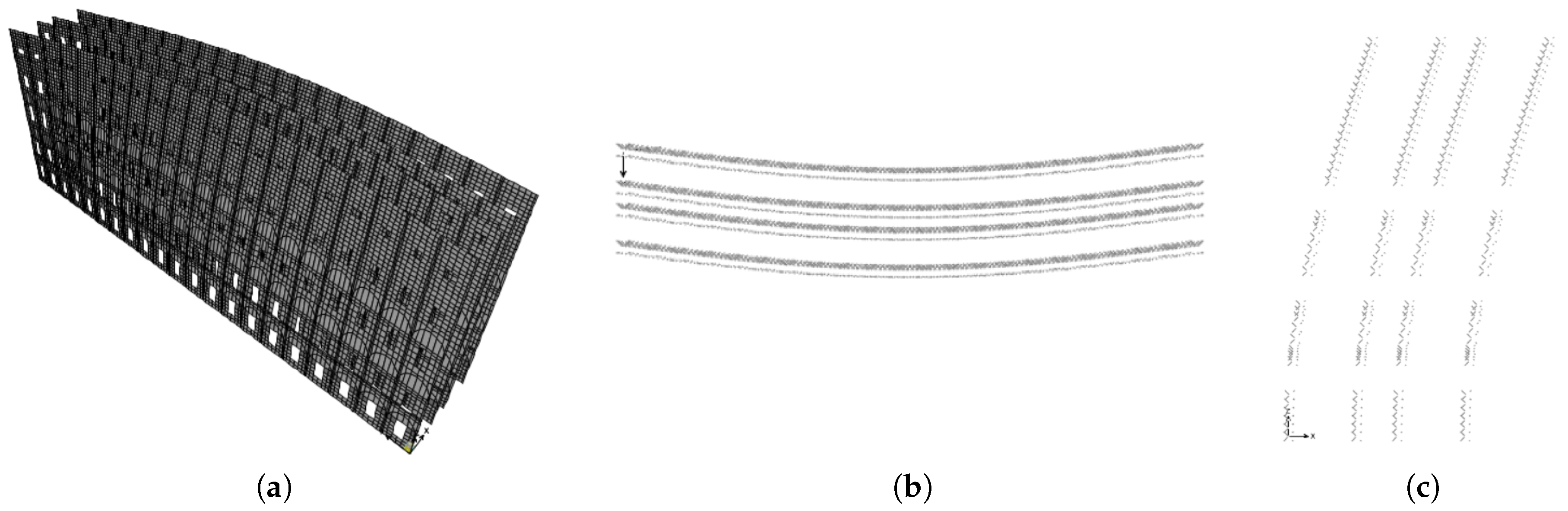
As a further step, the out-of-plane shear stiffness coefficient
is identified. To this aim, a central vertical strip of width
is extracted from the LW fine model. A distribution of horizontal forces, equivalent to the triangular load
with
N/m and
m, which is the total height of the wall, is applied to the external facade; the interaction with the adjacent strips is neglected. The out-of-plane displacement of the fine model is shown in
Figure 10a, in the 3D space, and in
Figure 10b, in the
plane. It is observed that the deformation is substantially similar to that of a shear-type frame with total height
, deriving by a
pure shear behavior of the interstory walls.
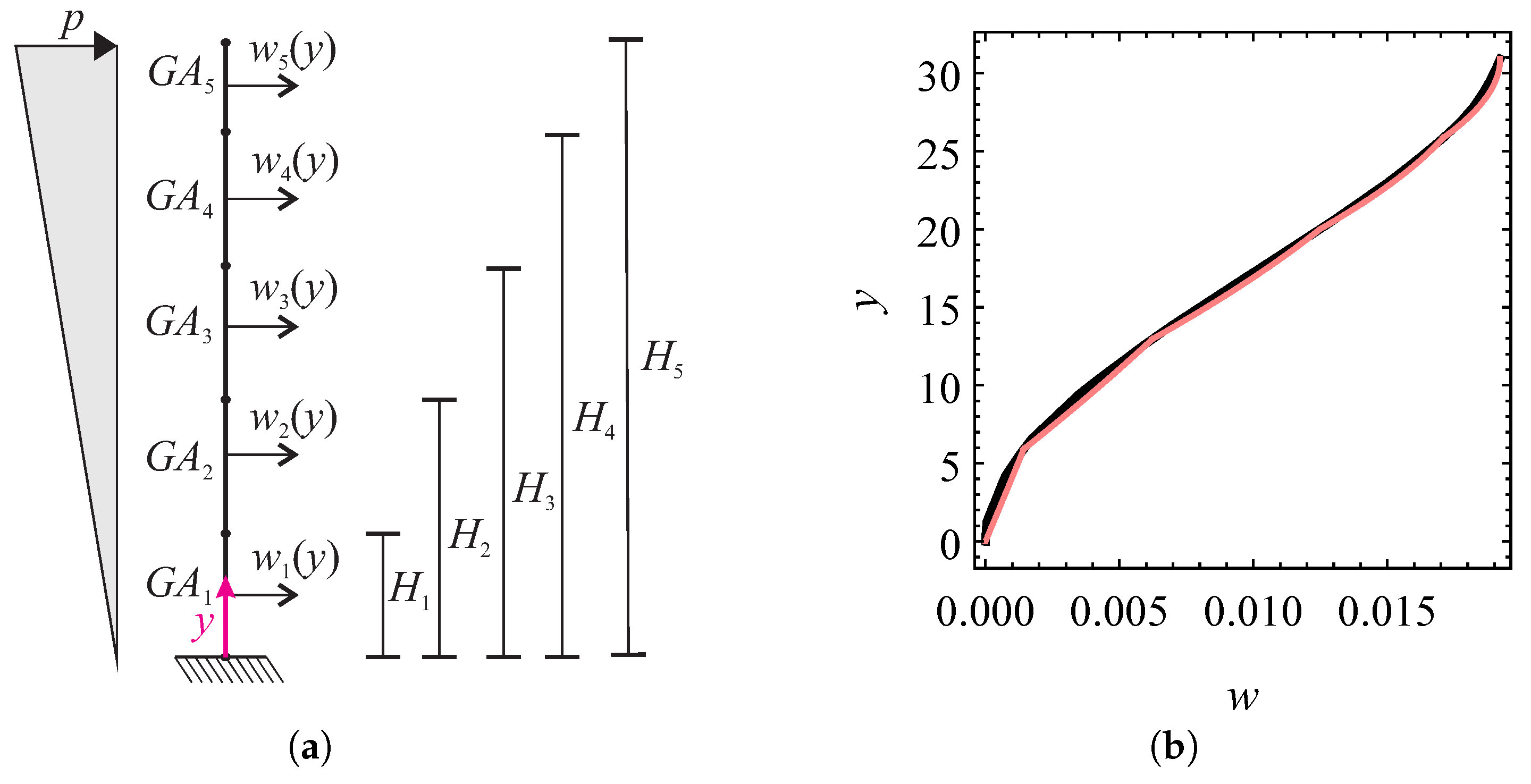
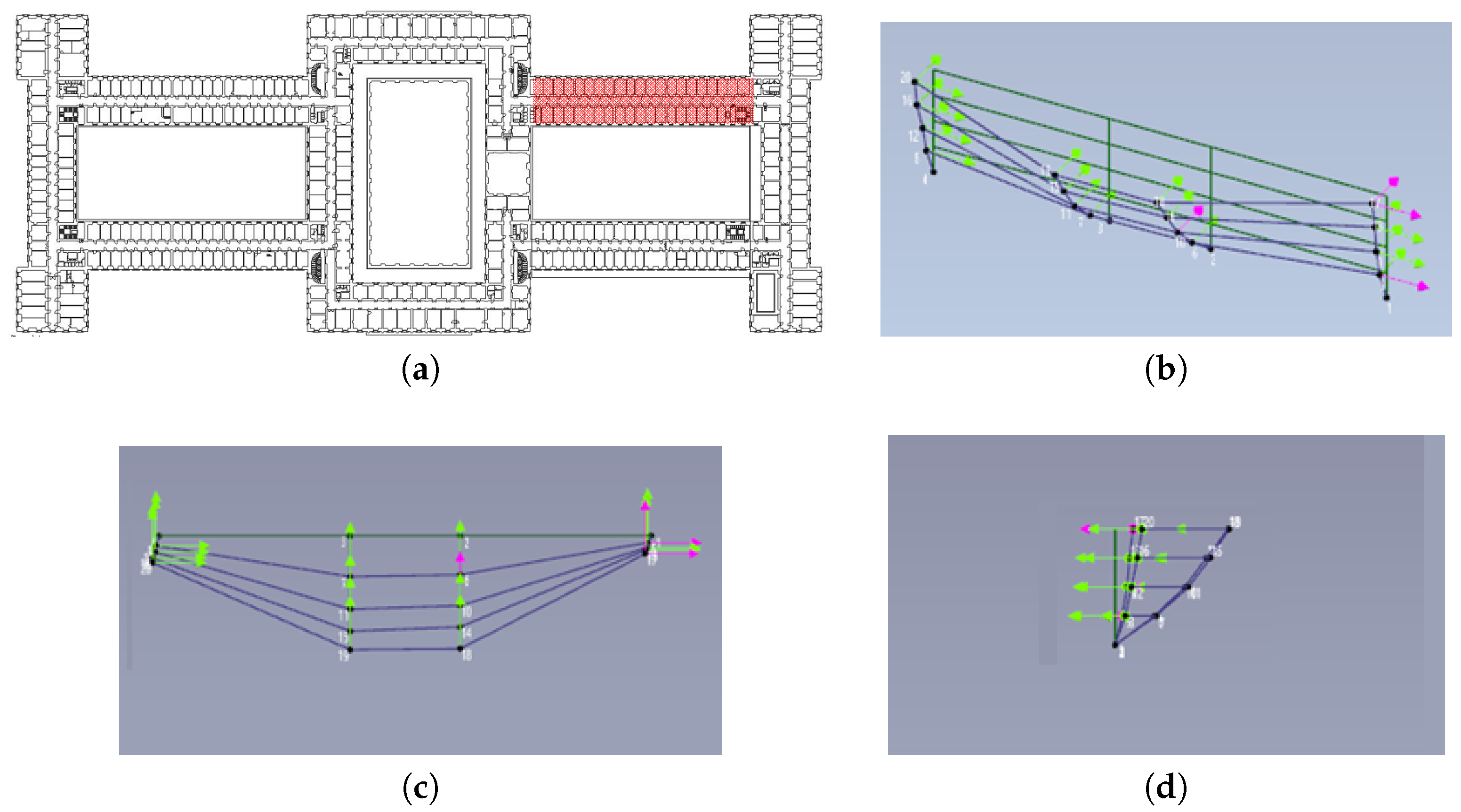
Therefore, for the aforementioned purpose, five equivalent pure shear beams, arranged in series and having axis-line along
y and length
, are considered. The shear beams are fixed at the base and subjected to the triangular load
; see the scheme in
Figure 11a. The identification of the relevant shear stiffness coefficients
(
) is carried out, as for the previous case, by a displacement equivalence between numerical and analytical models: The out-of-plane displacement of the fine model, evaluated at floor level
and at half width of the strip, is equated to the analytical expressions
. The latter come from solving the following differential boundary value problem, composed by field equations, continuity conditions at
and the geometric and mechanical conditions at the boundary:
The unknown equivalent stiffness coefficients
are consistently obtained and, accordingly, the plate stiffness coefficients are
; their numerical values are shown in
Table 2. In
Figure 11b a comparison between the deformed configurations of analytical and numerical models in the
plane are shown, indicating a very good agreement.
5.3. Summary of the Identified Equivalent Parameters
In accordance with the homogenization procedures described above, the numerical values of the identified stiffness coefficients (in N/m) for the LW homogenized model are collected in
Table 2 for each plate.
6. LTW and SLTW Homogenized Models Identification
The LW homogenized model is enriched by adding first the distributed, and then both distributed and localized transverse walls, thus obtaining the LTW and SLTW homogenized models, respectively. In particular, in the LTW model, the transverse walls are distributed along the total length L of the arm, with an inter-axis , and affect in- and out-of-plane stiffness coefficients and of the equivalent plate. Furthermore, in the SLTW model, the localized transverse walls are modeled as equivalent beams, integral with the LTW plate.
6.1. In-Plane (Membrane) Behavior
The transverse walls are assumed to influence the in-plane behavior of the equivalent plate in the y-direction. They are modeled as beams with axis-line along y, having axial stiffness , where m is the cross-section area for the case of distributed walls, and m for localized walls, respectively.
Therefore, in defining the LTW homogenized model, the contribution of the distributed beams on the equivalent plate turns out to be an increase of the elastic coefficient
of the LW model, given in Equation (
2), of the value
N/m.
For the SLTW homogenized model, a further stiffening of the LTW model is due to the localized beams, which are integral with the plate and provide axial stiffness (in which the contribution of the partitions, incorporated in the plate, is subtracted).
6.2. Out-of-Plane (Shear) Behavior
In order to evaluate the out-of-plane behavior, each couple of transverse wall is modeled as a Timoshenko beam having an axis-line along
y. Its bending and shear stiffness coefficients are piece-wise uniform along each story, and are evaluated as
and
(for
), respectively, where principal inertia moment
and area
include the thickness of the two external and internal longitudinal walls to the cross-section of each transverse wall. However, since the beams are included or attached to the pure shear plates of the homogenized model, they are forced to behave as pure shear beams as well. For this reason, a “reduced” equivalent shear stiffness
(for
), also including the bending of the Timoshenko beams, is identified. This is made by a complementary energy equivalence between the Timoshenko beam (bending and shear stiffness coefficients
,
, respectively) and a pure shear beam (shear stiffness
), of length
, fixed at the base and subjected to a horizontal load at the top (details are given in
Appendix A). The equivalent shear stiffness is found to be:
In defining the LTW homogenized model, the contribution of the distributed walls is finally included in the equivalent plates as
(reported in
Table 3).
Then, the SLTW homogenized model is defined, by stiffening the LTW model by localized beams, integral with the plate and having shear stiffness
reported in
Table 3 (the contribution of the partitions, incorporated in the plate, is subtracted).
Note that the shear stiffness of the LTW model is much higher than that of the LW model.
7. Global Homogenized Model
The case study consists of a very large building and this makes the finite element fine modeling very heavy and somehow impractical for the characterization of a possible global behavior. Therefore, the definition of a simplified homogenized model, with a reduced number of d.o.f., appears as a convenient choice, when one is interested to address a large scale point of view. The purpose is indeed accomplished by substituting each arm of the building with five (one for each story) homogeneous plates. In this way, the building is thought of as a vertical tube, with a multi-cellular section. In order to obtain a minimal and descriptive model of the dynamic behavior, despite the heterogeneity of the building, the same mechanical characteristics are assigned to the plates composing the different arms. The latter are defined by the LW, LTW, or SLTW homogenized models of the long longitudinal arm, as defined in the previous sections.
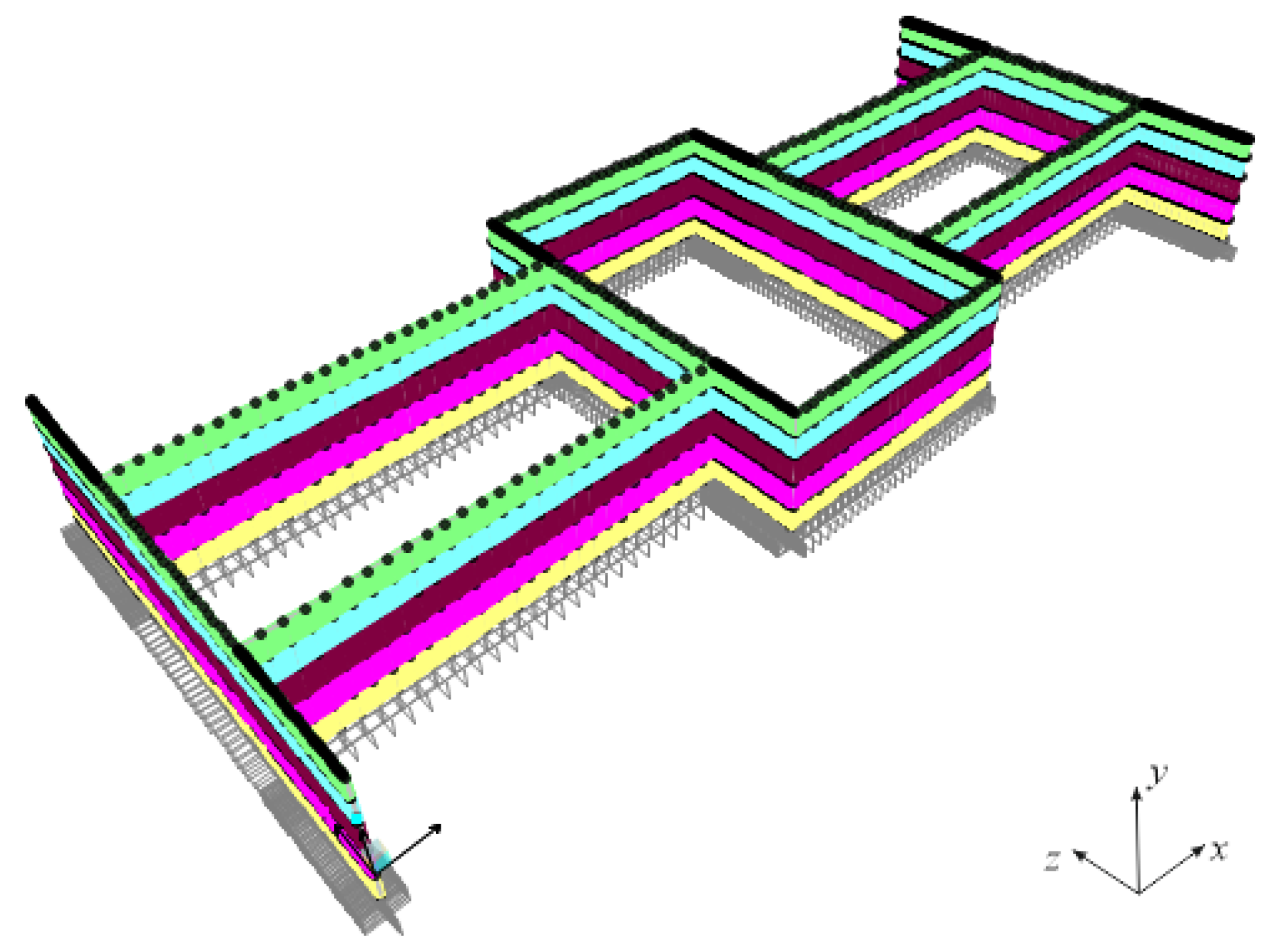
A perspective view of the finite element global homogenized model is shown in
Figure 12. It consists of 4848 nodes and 4150 elements. The walls are modeled by in-series homogeneous orthotropic shell elements, of unitary out-of-plane thickness and having the length of the arm and interstory height. Any element is a Cauchy continuum body in plane stress, defined in a 2D space. Different colors are used to distinguish the mechanical properties of each plate, defined by the LW or LTW homogenized models; localized massless beam elements are attached to the plates, when the SLTW homogenized model is considered. For details about the geometry, see
Figure 1 The soil–structure interaction is not taken into account; therefore, external fixed constraints are applied to the base nodes.
8. Modal Analysis
First, experimental dynamic identification, carried out on building portions by R. Alaggio and E. Antonacci of the Structural Dynamic Laboratory of the University of L’Aquila (Technical Report not yet published at the time this paper is submitted, see Acknowledgments), is described. Then, modal analyses of the fine models of a building portion are performed to study the influence of the transverse walls; these models are also validated on the base of the experimental results. Modal analyses of the homogenized models of the same building portion are also performed and the models validated. Finally, the dynamic behavior of the global homogenized model is studied to address possible local and global mechanisms.
8.1. Experimental Dynamic Identification
The experimentation was carried out to assess the dynamic behavior of the building, according to the Output Only identification techniques, having the merit of reducing interference with the activities carried out routinely in the building. The processing of the acquired data is carried out according to methods defined in the time (SSI, Stochastic SubSpace Identification) and frequencies (EFDD, Enhanced Frequency Domain Decomposition) domain, in order to produce a mutual validation of the modal parameters (frequencies, forms, and modal damping). The dynamic investigations are developed in two phases: (i) a first phase of design and execution of the dynamic tests; (ii) a second phase of identification of the modal parameters. Similar techniques were used also in [
38,
39].
Two test campaigns, involving a portion of the building, were carried out at two different times:
The
test campaign 1 was carried out on the building portion highlighted in
Figure 13a, at the only second floor. The measuring instruments were arranged to measure the components of the motion at twelve points and, for each point, in two directions.
The
test campaign 2 was carried out on the building portion highlighted in
Figure 14b at the first, second, third, and fourth floor. Four measuring instruments were arranged at each floors in order to measure the motion components in sixteen points.
Excerpts of the natural frequency and modal shapes of the first vibrating mode, obtained in both the campaigns, are shown in
Figure 13 and
Figure 14. It is observed that the first vibrating mode mainly involves the out-of-plane behavior of the longitudinal arm, with the decidedly high natural frequency
Hz.
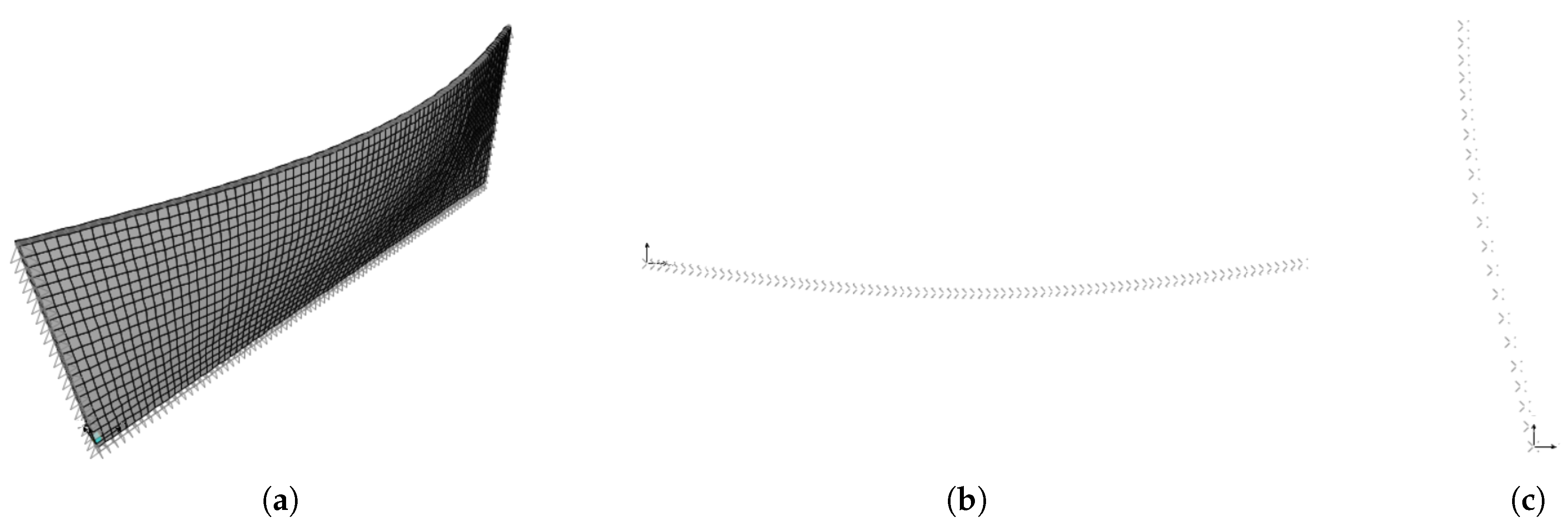
8.2. Modal Analysis of the Fine Models of a Building Portion
The modal analysis of the LW, LTW, and SLTW fine models of the long longitudinal arm is performed, in order to investigate the actual influence of the transverse walls on the dynamic behavior. The corresponding natural frequencies and modal shapes of the first natural mode are shown in
Figure 15,
Figure 16 and
Figure 17.
First, it is seen that the first vibrating mode mainly involves the out-of-plane behavior of the structure. The LW model is the less stiff, with a natural frequency
Hz. Moreover, pure shear modal shapes are observed in the
and
planes. Concerning this aspect, some considerations about the significant influence of the slabs are reported in
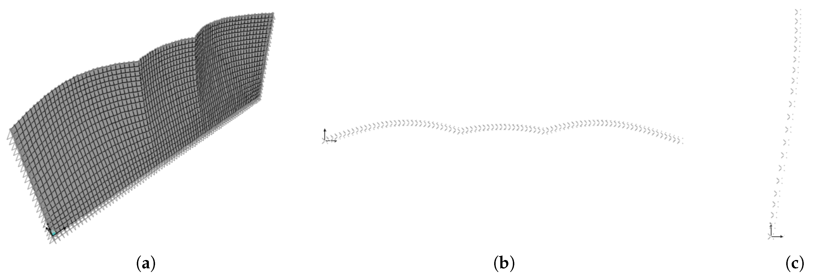
Appendix B. However, when the distributed transverse walls are introduced, a significant increasing of the natural frequency reasonably occurs (the natural frequency of the LTW model is
Hz), together with a qualitative change of the modal shape in the
plane, in which also a bending behavior of the transverse walls is observed. Finally, the adding of the localized transverse walls further increases the frequency (the natural frequency of the SLTW model is
Hz) and, mainly, modifies the modal shape in the
plane, in which localized stiffening effects are evident.
By comparing the numerical results with the experimental ones of
Section 8.1, it is evident how decisive appears the contribution of the transverse walls. The SLTW fine model captures quite well the experimental results, with a percent error in frequency of about
%. However, an evident error is related to the hinge constraints at the lateral sides of the longitudinal walls of the fine model, which could be conveniently substituted by horizontal springs (appropriately calibrated, possibly in further investigations).
8.3. Modal Analysis of the Homogenized Models of a Building Portion
The modal analyses of the LW, LTW, and SLTW homogenized models of the same longitudinal arm are performed, with the purpose of validating the (rough) homogenized models by means of the corresponding fine ones, as well as evaluating how the natural frequency provides a “global” measure of the accuracy of the homogenization procedure. Natural frequencies and modal shapes of the first natural mode are shown in
Figure 18,
Figure 19 and
Figure 20.
8.4. Modal Analysis of the Global Homogenized Model
Finally, the modal analysis of the global homogenized model is carried out. The aim is to investigate the occurrence of a global dynamic behavior rather than local mechanisms of macro-elements. It is worth noticing that such an analysis, if performed with a fine model of the whole structure, is impractical.
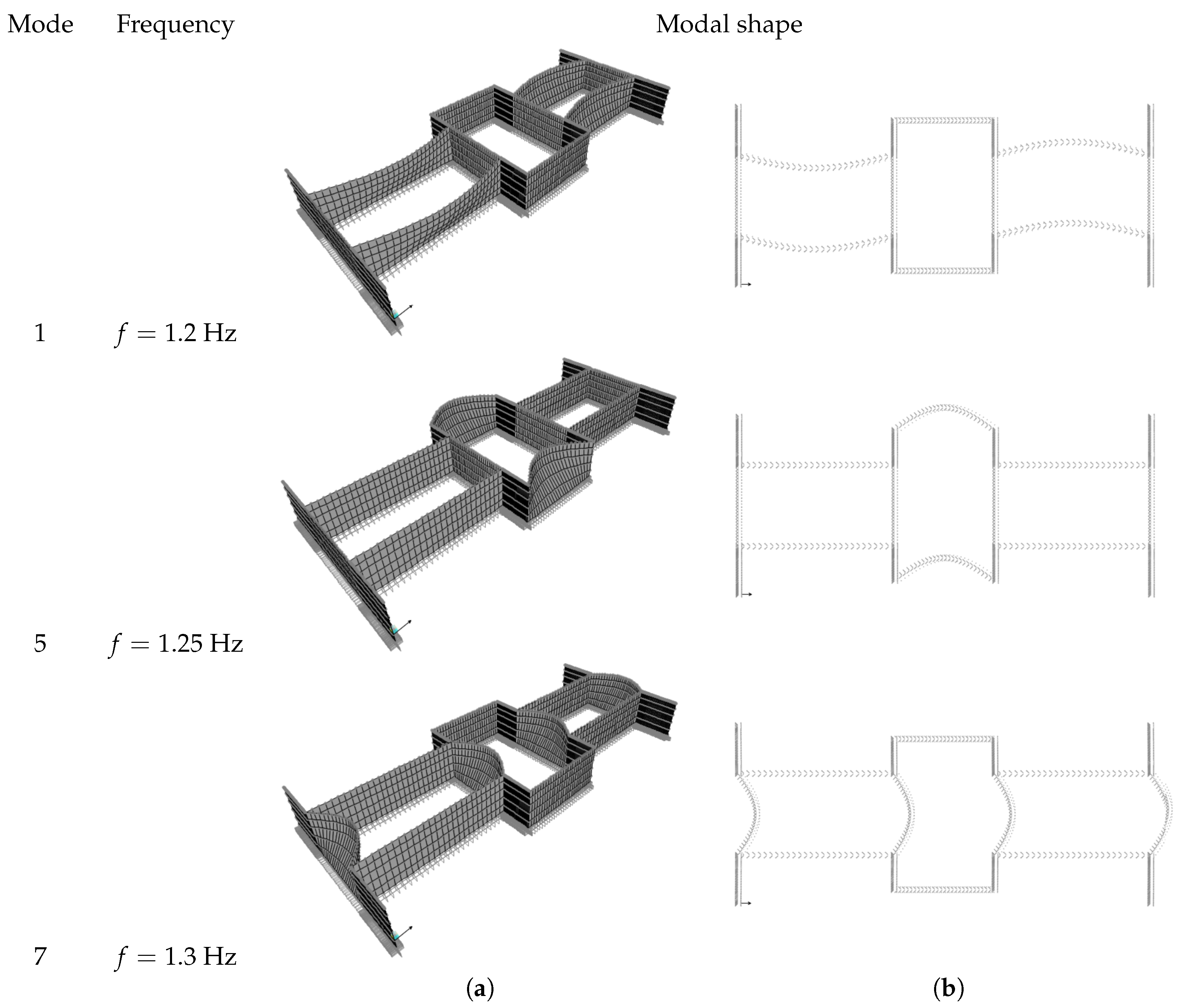
First, the global LTW homogenized model is studied. It is found that the dynamic behavior is characterized mainly by out-of-plane movements of macro-elements, composed by the building arms. Frequency and modal shape of the most qualitatively significanty natural modes, namely 1,5,7, are shown in
Figure 21. In particular, the natural modes 1–4 involve the long longitudinal arms with frequencies of about
Hz, the natural modes 5–6 involve the short longitudinal arms with frequencies of about
Hz and the natural modes 7–10 involve the transverse arms with frequencies of about
Hz.
Moreover, as a confirmation of the occurrence of local dynamic mechanisms, it is observed also that the first mode is about the same as that of the homogenized model representing the only longitudinal arm (see
Figure 16). This specific aspect is mainly due to the geometry of the building, and allows one to directly address the study to the single arms, eventually developing finer models.
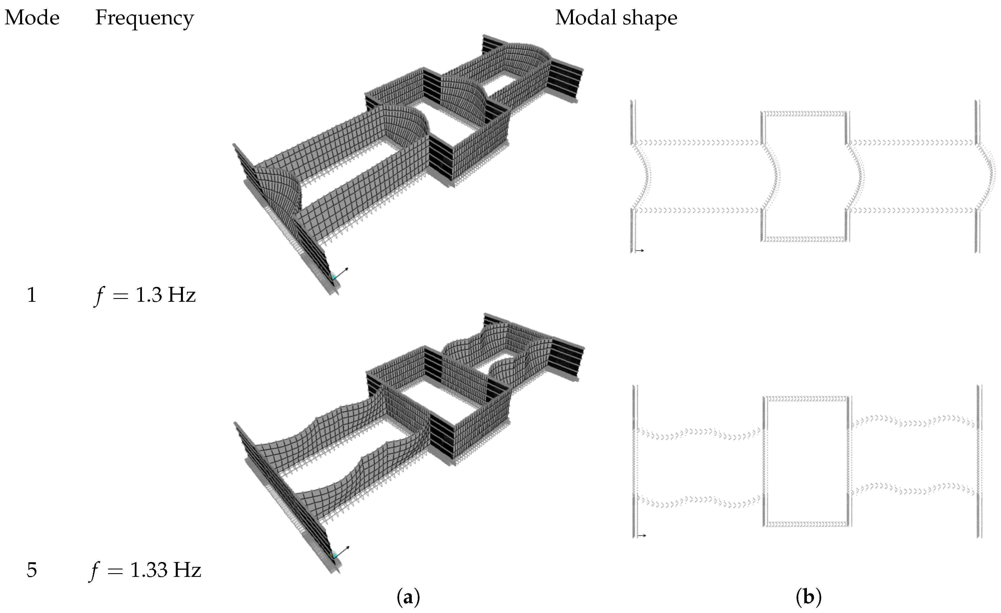
When the localized transverse walls are added and the global SLTW homogenized model is studied, the dynamic behavior continues to be characterized mainly by out-of-plane local movements of macro-elements, consisting of the building arms. Frequency and modal shape of the natural modes 1, 5 are shown in
Figure 22. The natural modes 1–4 involve the transverse arms with frequencies of about
Hz and the natural modes 5–8 involve the long longitudinal arms with frequencies of about
Hz; the other modes are the higher modes of the long longitudinal arms and, therefore, are not reported.
It is interesting to note that the addition of localized beams, as defined in the SLTW model, causes a reversal of the modes order. This is a consequence of the effect of the localized walls, which increase the out-of-plane modal stiffness of the arms in a different way, depending on the mode number. Indeed, compared to the frequency of the modes 1, 5, 7 of the LTW model, where localized transverse walls are absent, for the SLTW, it is increased of %, 39% and , respectively. As a further observation, the natural frequencies of the global SLTW homogenized model are very close to each other, so as to result in being very sensitive to the definition of the localized elements. This aspect could induce, for some configurations, the occurrence of simultaneous modes, which might be worthy of investigation.
9. Conclusions
In order to have a clear insight into the dynamic behavior of a vast historical building, a homogeneous mechanical model has been addressed here. This specific approach has been motivated by the structural characteristics of the building, constituting of a complex assembly of masonry walls, vaults, arches, slabs, which make in fact impractical the realization of a refined finite element model. The homogeneous model is made of linear orthotropic plates, which change their elastic properties at any story; furthermore, in the definition of the material response function, it has been taken advantage of the feasible individuation of a Representative Volume Element, from the periodic repetition of male walls and windows.
Three possible versions have been formulated, referred to as LW, LTW, and SLTW, respectively, where the equivalent plate has been progressively enriched with the contributions of distributed and localized beams, so as to account for the effects of the transverse walls. Specifically, structural models of Mindlin–Reissner plates, alternatively combined either with Timoshenko or pure shear beams, have been used depending on the representation of in-plane or out-of-plane behavior. The corresponding constitutive parameters have been then calibrated with the use of fine FE models of portions of the building.
It has been seen how the obtained homogeneous models are handy and, as a major result, well capture the first modal properties of the building, as compared to outcomes of experimental dynamic identification which are carried out for practical reasons only on a portion of the structure. Moreover, the homogeneous model allows one to analyze the global behavior of the building, providing a significant interpretation of the relationship intercurring between global and local mechanisms. Notably, it has been found that dynamics are mainly characterized by out-of-plane movements of the macro-elements composed of the building arms, thus addressing how the local mechanisms concur in delineating the global behavior of the structure. This aspect is a consequence of the specific geometry of the building, and justifies the possibility of directly addressing the study to the single arms, eventually developing finer models.
With reference to the LTW model, it turns out that the natural modes 1–4 involve out-of-plane motions of the long longitudinal arms, with frequencies of about Hz, while modes 5–6 involve the short longitudinal arms, with frequencies of about Hz, and modes 7–10 the transverse arms with frequencies of about Hz. Further improvement of the model, specifically referring to the SLTW configuration, causes a reversal of the modal order, possibly due to the closeness of the different natural frequencies and the high sensitivity of the model.


