Article

A Novel Self-Moving Framed Piezoelectric Actuator

1
State Kay Laboratory of Mechanics and Control of Mechanical Structures, Nanjing University of Aeronautics and Astronautics, Nanjing 210016, China
2
Department of Electromechanical Engineering, Faculty of Science and Technology, University of Macau, Macau, China
*
Author to whom correspondence should be addressed.
Appl. Sci. 2020, 10(19), 6682; https://doi.org/10.3390/app10196682
Submission received: 14 August 2020 / Revised: 21 September 2020 / Accepted: 22 September 2020 / Published: 24 September 2020
(This article belongs to the Section Electrical, Electronics and Communications Engineering)

Abstract

:
Utilizing the inherent advantages of the piezoelectric driving technology, such as good adaptability to vacuum environment and no electromagnetic interference, a novel self-moving framed piezoelectric actuator is proposed, simulated, and tested in this study, holding a potential application for magnetic confinement fusion. Four piezoelectric composite beams form a framed piezoelectric actuator. Two orthogonal vibration modes are excited and coupled in the framed piezoelectric actuator, producing a microscopic elliptical motion at its driving feet. Due to the friction, the framed piezoelectric actuator can move on a rail, thereby constructing the railed carrying system. Numerical simulation is carried out to confirm the operation principle and to conduct the dimensional optimization of the proposed framed piezoelectric actuator. A prototype of the proposed framed piezoelectric actuator with a weight of 83.8 g is manufactured, assembled, and tested, to verify the piezoelectric actuation concept. The optimal driving frequency of 20.75 kHz is obtained for the proposed actuator prototype, and at the excitation voltage of 400 Vpp its maximum mean velocity of 384.9 mm/s is measured. Additionally, the maximum load weight to self-weight of the proposed actuator prototype reached up to 10.74 at the excitation voltage of 300 Vpp. These experimental results validate the feasibility of the piezoelectric actuation concept on the railed carrying system.

1. Introduction

In recent times, piezoelectric driving technology has been widely applied in many engineering fields with requirements of high precision and high speed [1,2,3]. This is due to its advantages of simple in structure, high resolution, high response speed, and good environmental adaptability [4,5]. As a representative of the piezoelectric driving technology, piezoelectric actuators have been successfully employed in aerospace, robotics, medical instruments, and a large number of MEMS devices [6,7,8,9]. In general, piezoelectric actuators can be classified into non-resonant and resonant types according to their working states [10,11,12,13]. The non-resonant piezoelectric actuator operates below its first resonance frequency so that it can achieve high-precision positioning with a nanometer scale [11]. However, this kind of piezoelectric actuator is usually inefficient, and its output speed is limited. Moreover, it produces noise during operations due to the low driving frequency. For instance, Liu et al. proposed a two-dimensional linear piezoelectric stepping platform by applying longitudinal and bending deformation of a piezoelectric actuator [14]. This platform obtained a high resolution of 1 μm, while its output velocities under no-load condition were 101.7 μm/s and 124.2 μm/s in two directions. Wang et al. designed a linear inchworm piezoelectric actuator with a minimum positioning resolution of 7 nm and a maximum output speed of 1.5 mm/s [15]. These cases indicate that the non-resonant piezoelectric actuators are hard to ensure the balance between high speed and high precision. In contrast, the resonant type piezoelectric actuators utilize single vibration mode or coupling of multi vibration modes to generate micro amplitude elliptical motion of their driving foot, and then the macro motion can be achieved due to the friction coupling effect [16,17]. This accumulation of micro-movement enabled resonant piezoelectric actuators to function with higher output velocity and more considerable movement travel. Additionally, the resonant piezoelectric actuators operate very quietly due to their driving frequency in the ultrasound range. The disadvantage for the resonant piezoelectric actuators is also obvious, which is the serious wear caused by the high frequency vibration. This shortcoming limits the service lifetime of resonant piezoelectric actuators.
According to the waveforms, the resonant piezoelectric actuators can be divided into standing wave and traveling wave types. The typical standing wave and traveling wave piezoelectric actuators are the V-shaped linear ultrasonic motor developed by Kurosawa in 1998 [18] and the rotatory ultrasonic motor proposed by Sashida in 1983 [19], respectively. To utilize the merits of direct drive and large travel of the resonant piezoelectric actuators, some piezoelectric actuated robots have been emerged. In 2006, Yan et al. developed a miniature-step piezoelectric mobile robot with four electromagnetic legs [20]. A piezoelectric stack was used to deform a rhombic flexible frame to achieve multi degrees of freedom of the robot. In 2013, Jin et al. proposed a novel tracked mobile system driven by a traveling wave piezoelectric actuator with four driving rings, eliminating the bearings, bogie wheels, and reducer mechanisms of traditional tracked systems [21]. In 2014, Hariri et al. designed a piezoelectric beam robot by gluing two non-collocated piezoelectric elements on a straight beam to generate traveling wave [22]. In 2016, Pan proposed a piezoelectric mobile micro robot by using a piezoelectric bimorph beam to stimulate the traveling wave of a frame body, which has a small volume of 10 cm3 [23]. In 2017, Hariri et al. developed a piezoelectric miniature legged robot driven by standing wave [24]. At the same time, Wang et al. proposed a sandwiched piezoelectric actuator with two driving rings to directly drive track by producing traveling wave in the driving rings for planetary exploration [25]. In 2018, Wang et al. developed a wheeled mobile system driven by a three-dimensional sandwich standing wave piezoelectric actuator for lunar rover [13]. In 2020, Hernando-García et al. designed a miniature legged robot driven by traveling wave, which was excited in a rectangular glass plate by two piezoelectric patches [26]. These developed piezoelectric actuators indicate that the piezoelectric driving technology holds the potential to construct different motion forms for mobile systems, including legged, tracked, and wheeled motions. This is due to the fact that it holds the merits of simple and compact structure, direct drive without any reduction mechanism, rapid response, no electromagnetic interference, self-locked when power off, high precision, and no lubricant.
Inspired by the aforementioned developed piezoelectric actuators, and combined with the merits of the piezoelectric driving technology, a novel self-moving framed piezoelectric actuator is proposed and investigated in this paper and employed to construct a railed carrying system, holding an application potential for magnetically confined nuclear fusion environment. A metal framed structure with gluing sixteen pieces of piezoelectric plates creates the proposed piezoelectric actuator. Utilizing a preload mechanism, the framed piezoelectric actuator can move on a rail by the friction effect, thus the railed carrying system is constructed.

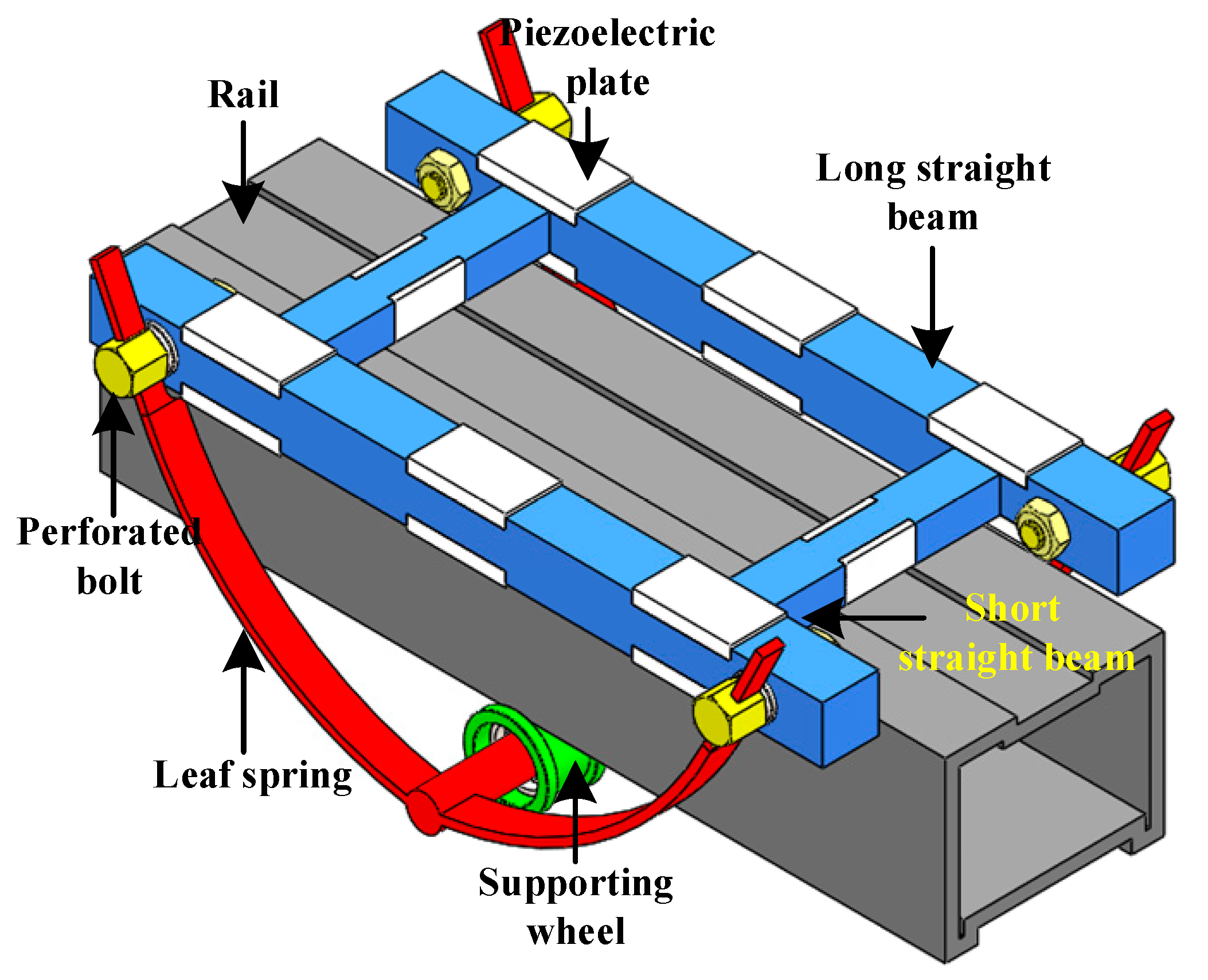
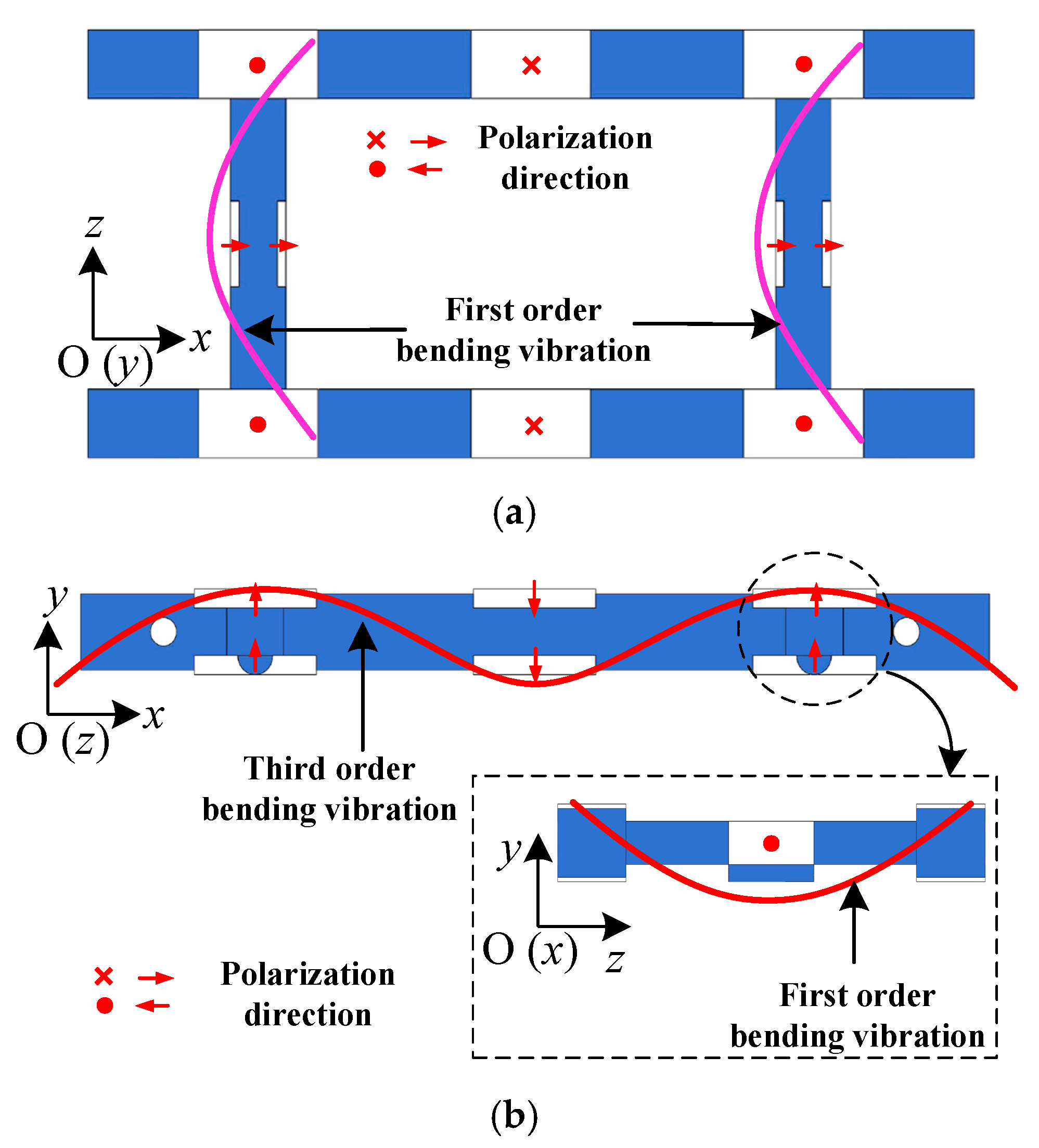
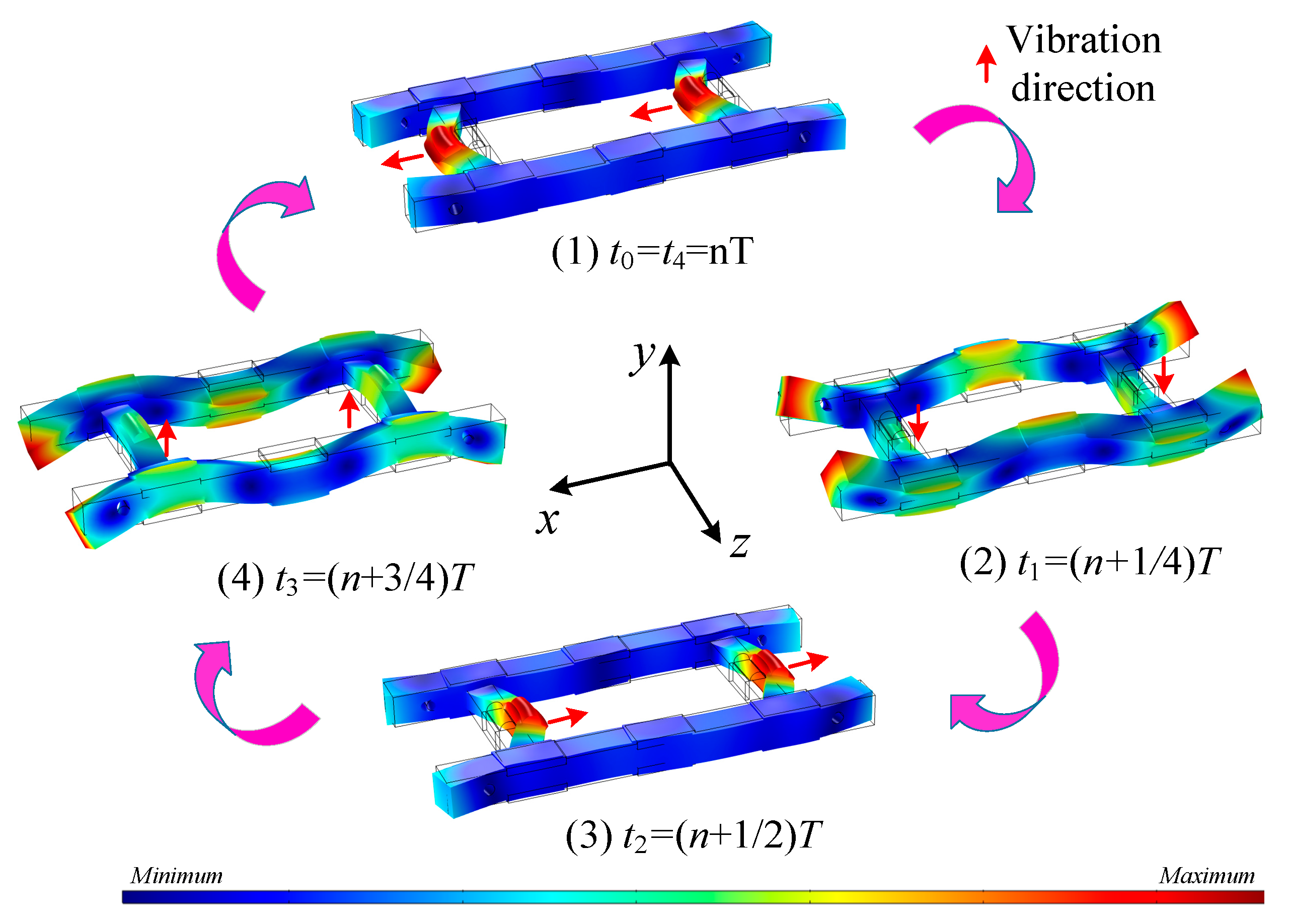
2. Configuration and Operating Principle

The configuration of the proposed framed piezoelectric actuator is depicted in Figure 1. The framed piezoelectric actuator is mainly composed of four straight beams (including two short and two long straight beams) bonded with sixteen pieces of piezoelectric plates. These piezoelectric plates are polarized along their thickness direction, and each straight beam with the glued piezoelectric plates form a piezoelectric composite beam. The two short piezoelectric composite beams are set in parallel to each other, and their two ends are perpendicularly connected with the two long piezoelectric composite beams, altogether constructing the rectangular frame structure of the piezoelectric actuator. Two projections located in the middle of the two short piezoelectric composite beams, respectively, are employed as the driving feet of the proposed framed piezoelectric actuator. The framed piezoelectric actuator, a rail, and a preload mechanism constitute a railed carrying system, as shown in Figure 1. The preload mechanism includes a pair of leaf springs, a pair of supporting wheels, and four perforated bolts. The supporting wheels locating in the middle of the leaf springs are in contact with the bottom surface of the rail. Both ends of each leaf spring are fixed on the long piezoelectric composite beam by two perforated bolts. Thus, the preload between the rail and framed piezoelectric actuator can be adjusted by altering the tension of the leaf springs. To minimize the impact of the leaf springs on the vibration characteristic of the framed piezoelectric actuator, all perforated bolts are fixed at the vibration node positions of the long piezoelectric composite beams.
In order to generate the elliptical motion of the two driving feet, two orthogonal operating vibration modes (Modes A and B) are selected to be excited in the proposed framed piezoelectric actuator, as shown in Figure 2. In mode A, the two short piezoelectric composite beams are excited to present the first order bending vibration along the x-direction when they are applied with a sinusoidal signal, as shown in Figure 2a. In this case, the two driving feet obtain a displacement component in the x-direction. As a cosine signal is applied to the two long piezoelectric composite beams, the third order bending vibration and the first order bending vibration both along the y-direction are stimulated in the two long and short piezoelectric composite beams, respectively, as shown in Figure 2b. This is mode B. Under this circumstance, the two driving feet vibrate along the y-direction. To maximize the excitation effect of all piezoelectric plates, they are located at the peak positions of corresponding vibration mode. While two voltage signals having a temporal phase difference of π/2 are simultaneously applied to the two long and short piezoelectric composite beams, respectively, the two vibration modes are coupled in the framed piezoelectric actuator, leading to that elliptical trajectories moving with the same direction are produced in the two driving feet. Thus, the framed piezoelectric actuator can move on the rail by friction, achieving the carrying system function. Once the two excitation signals have a temporal phase difference of −π/2, the elliptical trajectories of the two driving feet will be simultaneously reversed, resulting in an opposite motion of the railed carrying system.

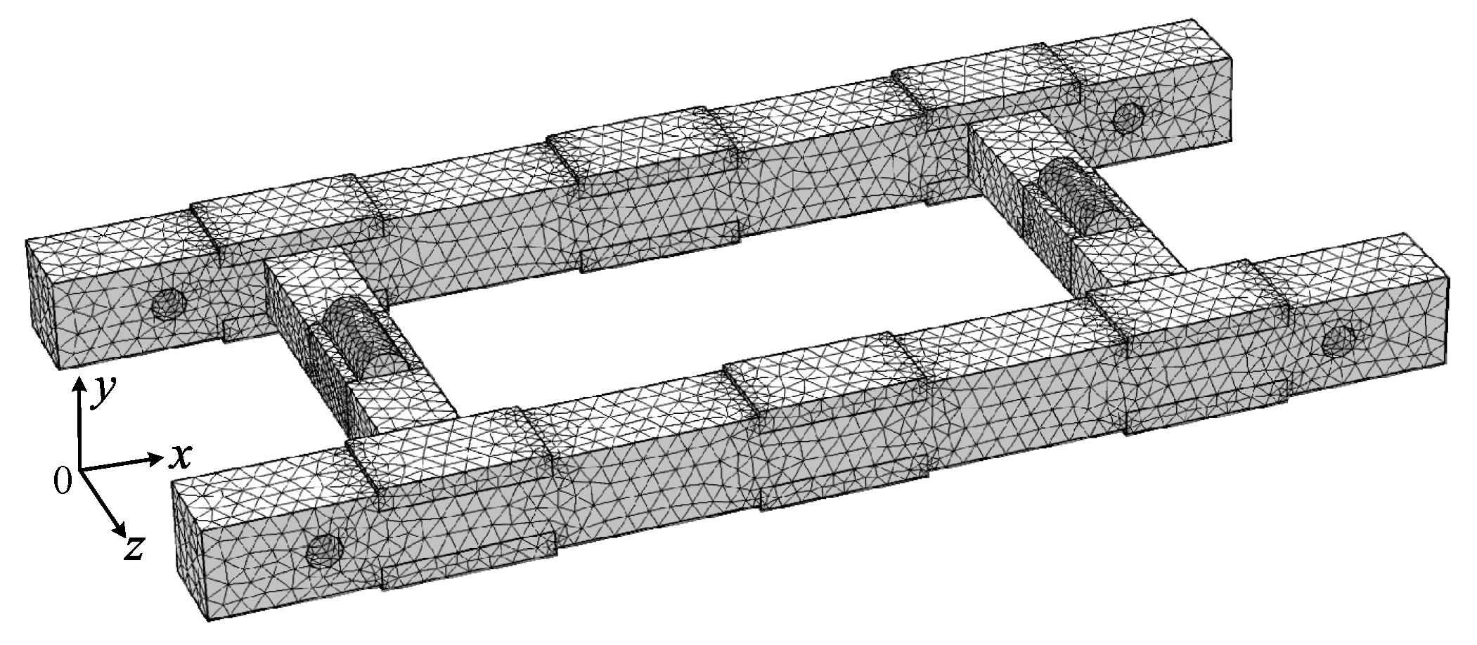
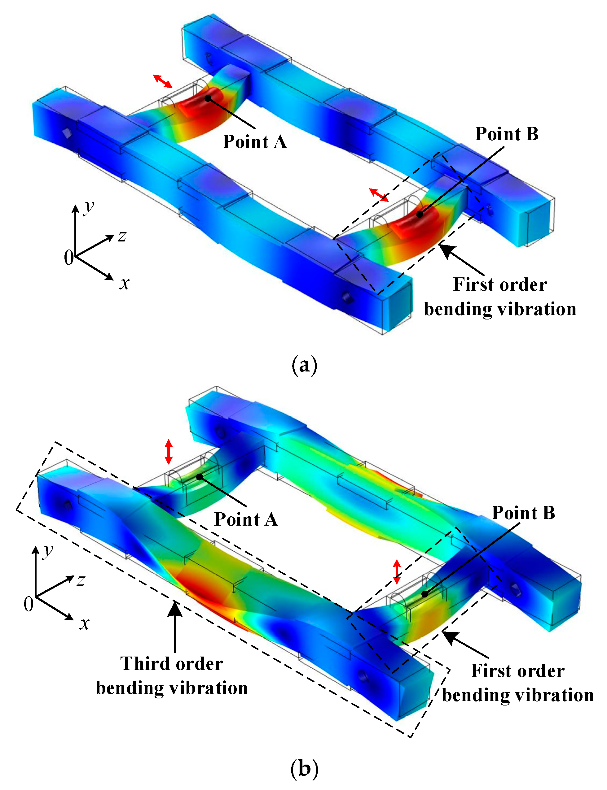
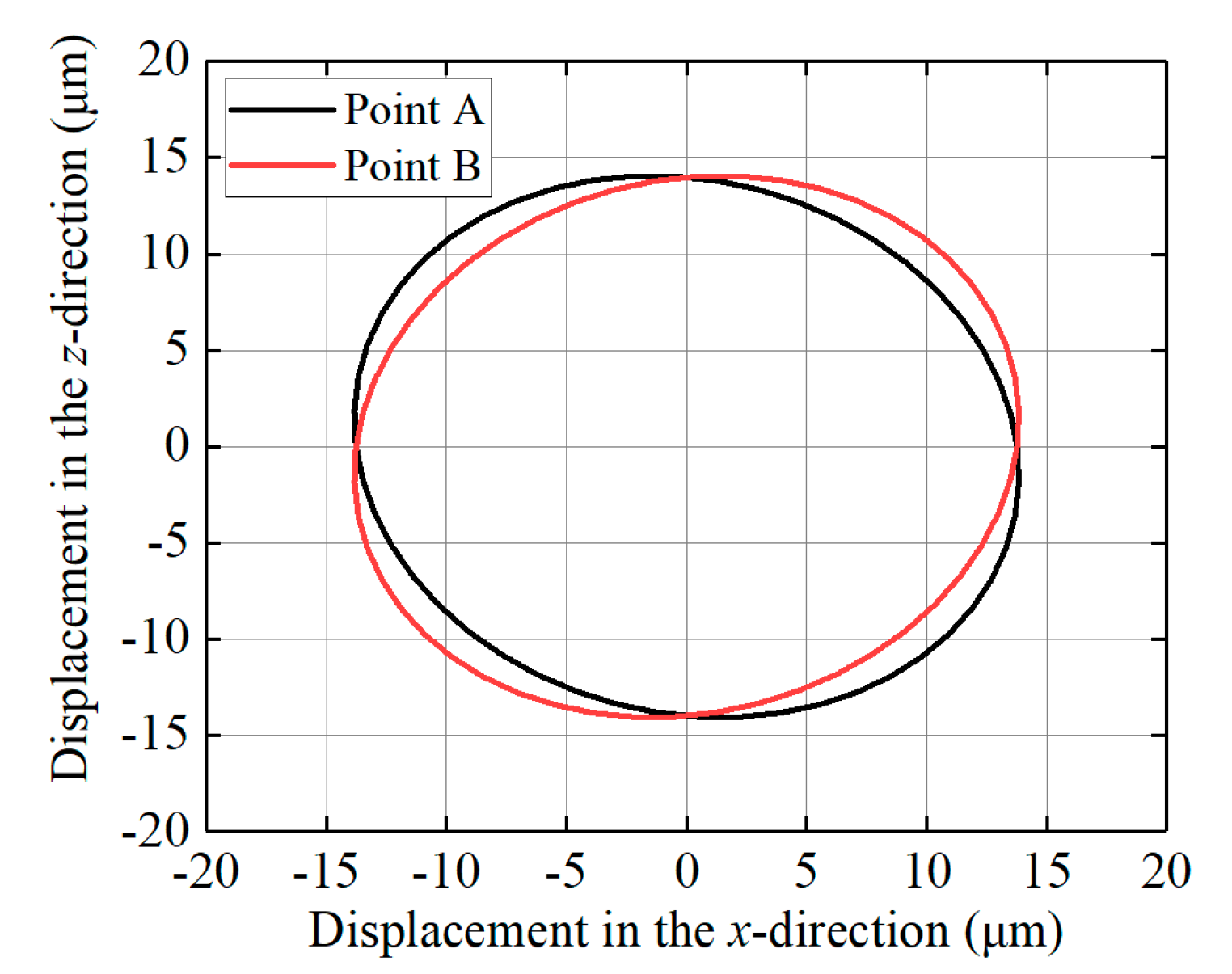
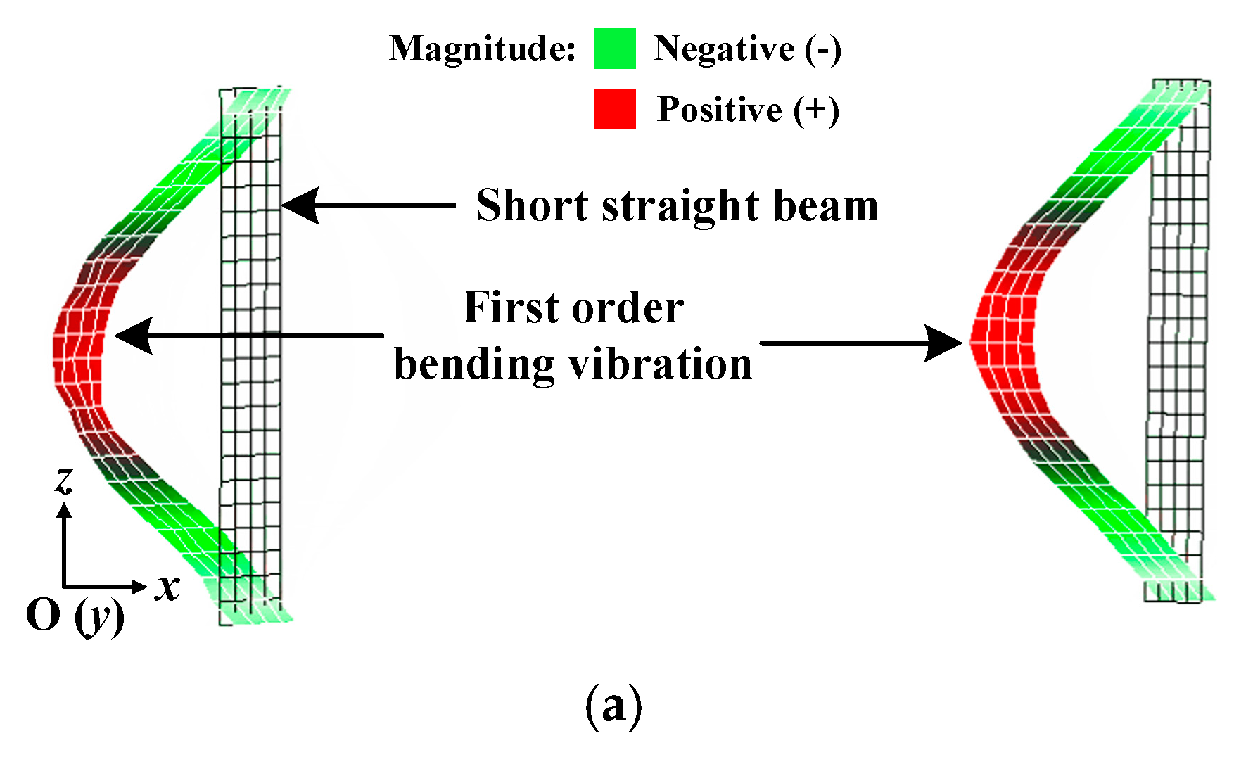
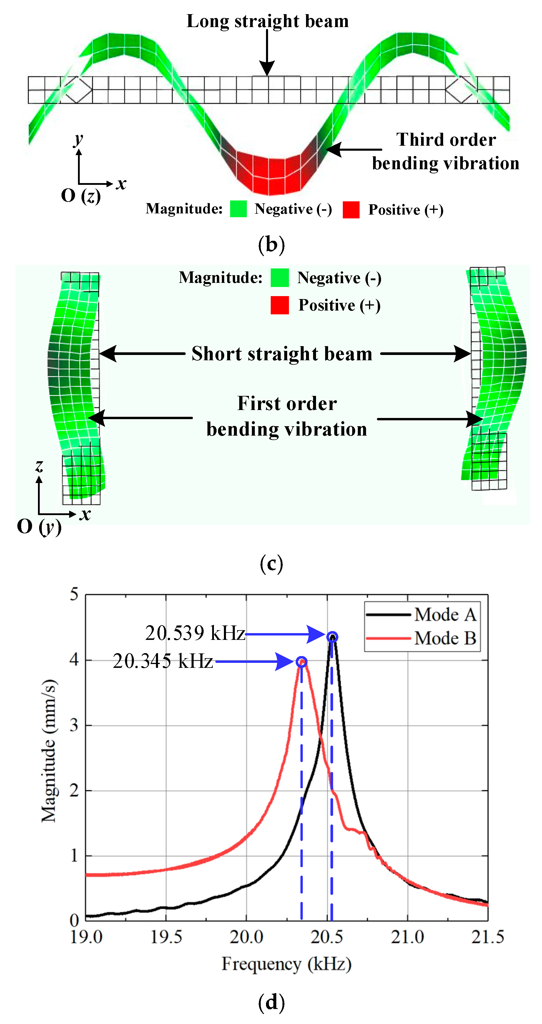
3. Numerical Simulation

To confirm the dimensional sizes of the framed piezoelectric actuator and to analyze its dynamic behavior, we conducted the numerical simulation in this section by using the commercial software COMSOL based on the finite element method. The four straight beams are made of titanium alloy (TC4), the PZT-8 type piezoelectric ceramic is selected as the piezoelectric plates, and their material parameters are listed in Table 1. Due to the fact that the selected piezoelectric plate bonded on the long straight beams has a dimension size of 14 mm × 8 mm × 2 mm, the width of the long straight beam is determined to be 8 mm. Additionally, piezoelectric plates with a dimension size of 10 mm × 5 mm × 1 mm bonded on the short straight beams confirm the height of the short straight beam in 5 mm. The other geometric parameters of the framed piezoelectric actuator were optimized in order to minimize the difference between the two operating resonant frequencies and to isolate other interference modes. The finite element model of the framed piezoelectric actuator was created, as shown in Figure 3. The type of all elements is free tetrahedral, and this finite element model was divided into 49,777 elements. The MUMPS (Multifrontal Massively Parallel Sparse Direct Solver) eigensolver was adopted for this finite element simulation. During calculation, all mechanical boundary conditions were free, and the zero voltage was applied to all piezoelectric plates as the electrical boundary condition. After a series of modal analysis simulations, the optimized geometrical sizes of the framed piezoelectric actuator were determined. The length of the short straight beam is 34 mm, and its cross-section is 5 mm × 6.5 mm. The long straight beam is 104 mm in length and has a cross-section of 8 mm × 8 mm. The two operating vibration modes were obtained, as shown in Figure 4. In the mode A, the two short straight beams vibrate at the first order bending vibration along the x-direction, and its corresponding resonant frequency is 20.498 kHz, as illustrated in Figure 4a. The resonant frequency of the mode B is 20.508 kHz when the third order bending vibration and first order bending vibration both along the y-direction are stimulated in the long and short straight beams, respectively, as shown in Figure 4b. The frequency difference of the two simulated resonant frequencies for the two operating vibration modes is 10 Hz, indicating that the simulation results meet the design requirement of the framed piezoelectric actuator.
Based on the optimized geometrical sizes of the framed piezoelectric actuator, the harmonic response analysis was carried out to study its dynamic behaviors. At first, we simulated the vibration shape variation during one excitation period. Two electric signals with a temporal phase difference of π/2 were applied to the piezoelectric plates located in the long and short straight beams, respectively, and an exciting frequency of 20.503 kHz was selected during the simulation. During one excitation period, the vibration shape of the framed piezoelectric actuator can be divided into four stages (from time t0 to t4, in which the period T = t4t0), as shown in Figure 5. It indicates that the vibration shapes of the framed piezoelectric actuator varied from (1) to (4) during one excitation period, in which the two driving tips moved with a completed elliptical trajectory.
Then, the motion characteristics of the two driving tips were calculated. The voltage, frequency and damping ratio were 100 V, 20.503 kHz, and 0.003, respectively. The motion trajectories of the driving feet (Points A and B) were calculated when the two vibration modes were excited and coupled in the framed piezoelectric actuator, as illustrated in Figure 6. It can be found that the motion trajectories of the two selected points are elliptical. A little difference can be seen for these two elliptical trajectories, indicating that the vibration characteristics of the two driving feet are not completely consistent. This is because the two driving feet are located in the middle of the two short beams, respectively, and their elliptical motion trajectories are symmetrical along the vertical coordinate axis due to the structural symmetry of the framed piezoelectric actuator. These simulation results confirm the feasibility of the design and operating principle of the proposed framed piezoelectric actuator.

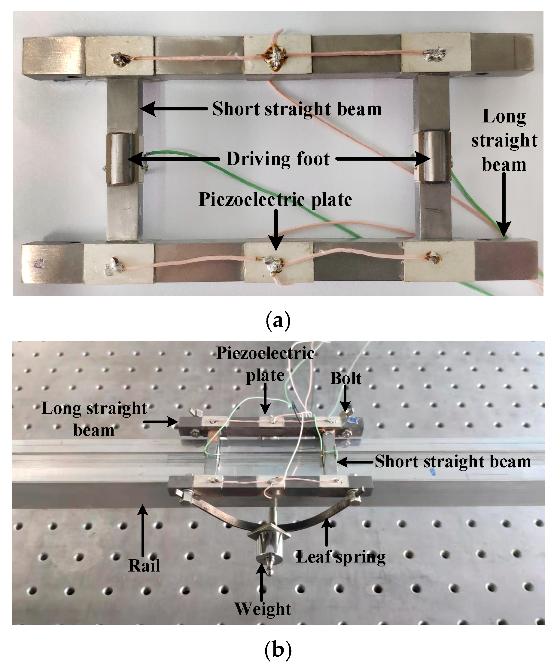
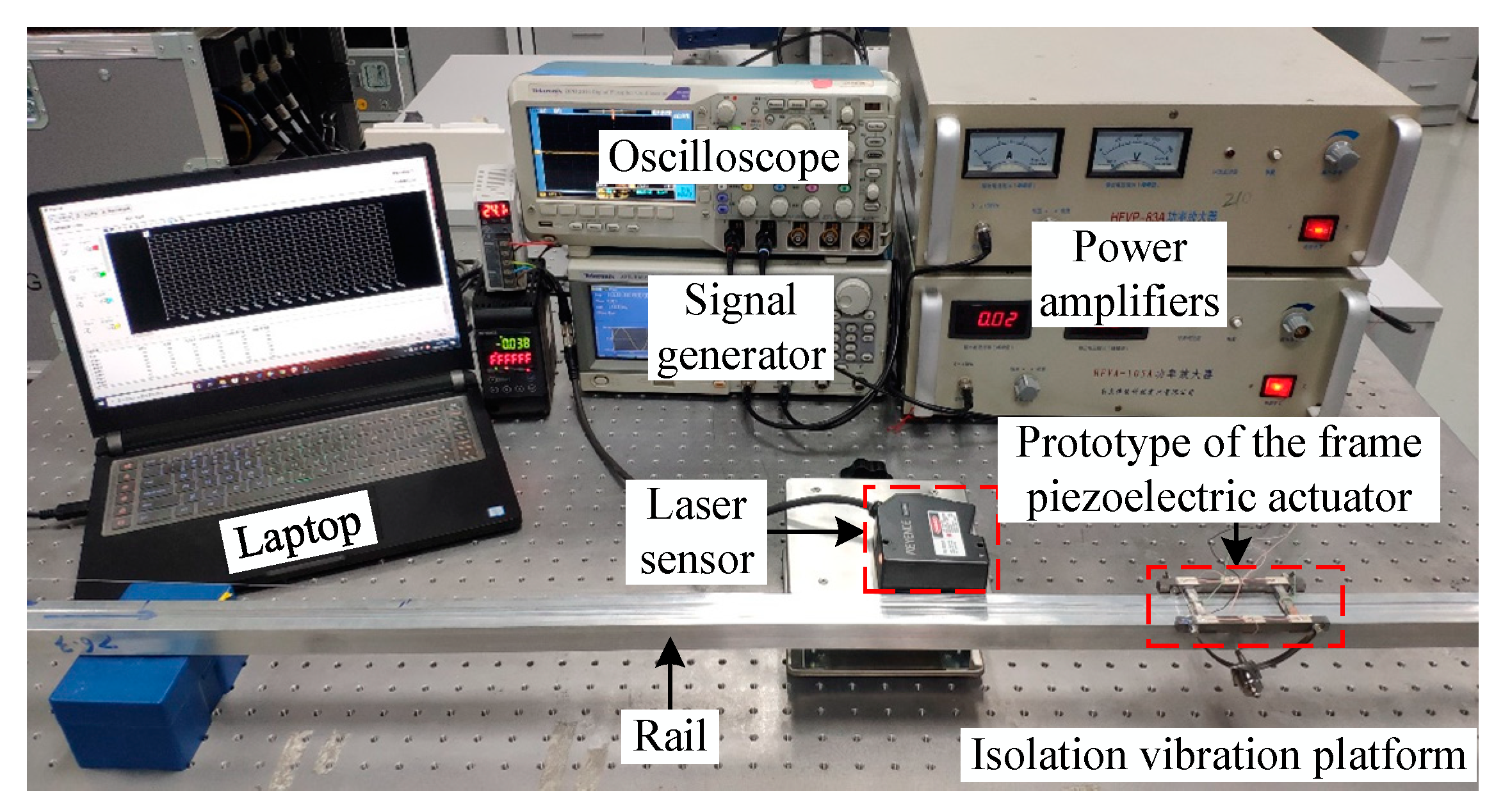
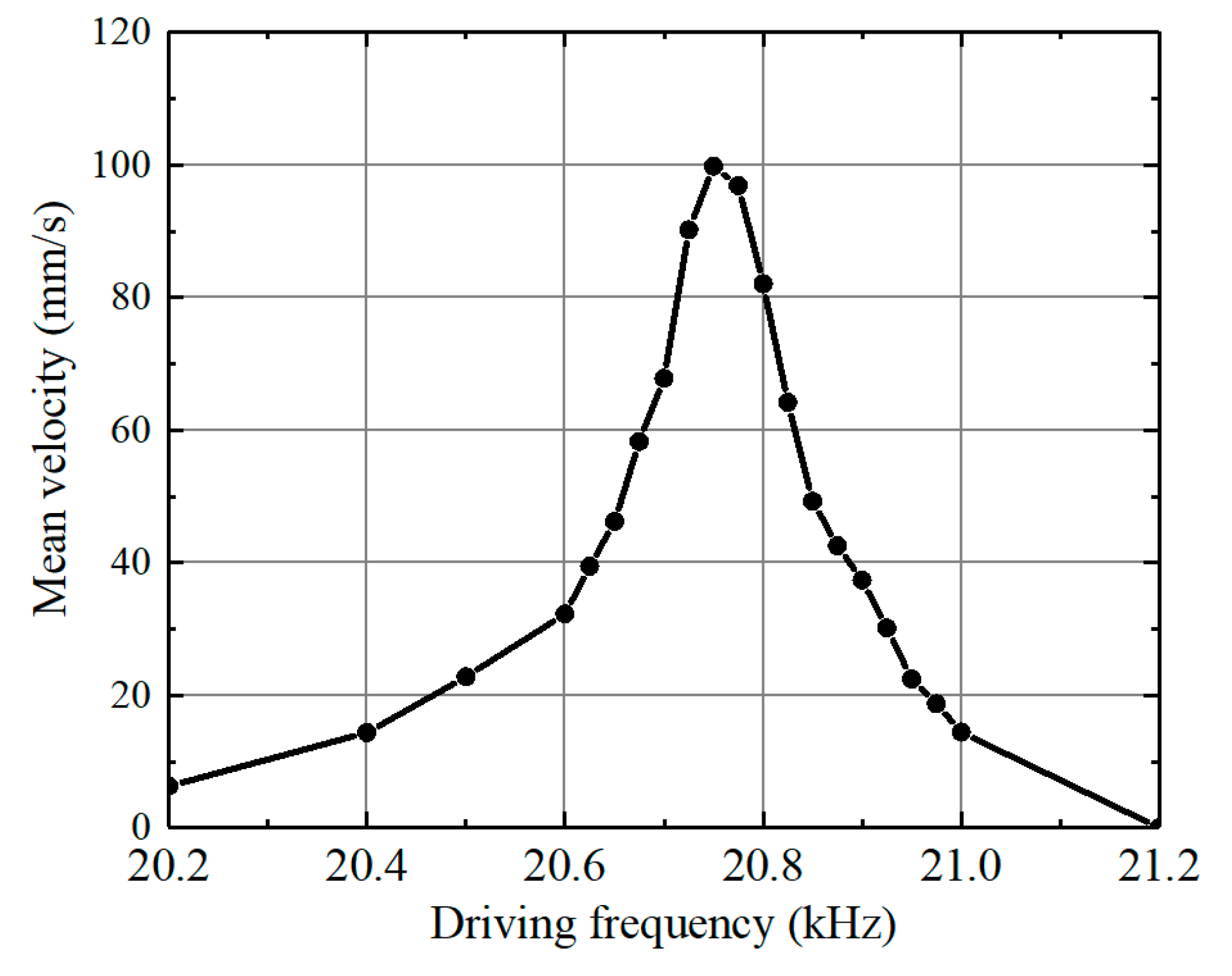
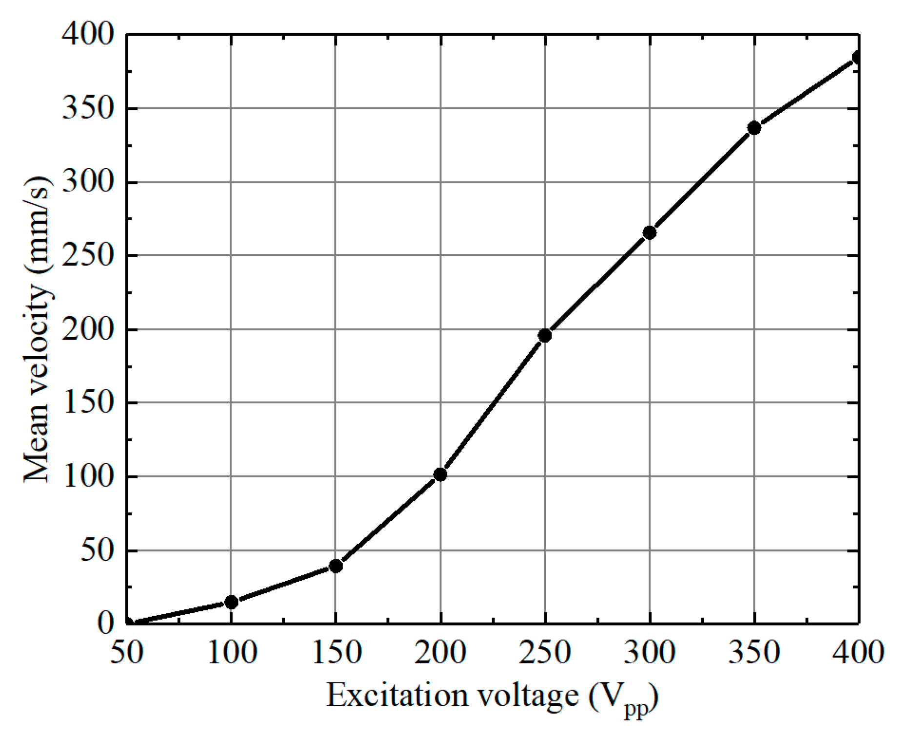
4. Experimental Investigation

The prototype of the framed piezoelectric actuator with a weight of 83.8 g was manufactured and fabricated based on the finite element simulation results, as shown in Figure 7a. And the assembled railed carrying system prototype is illustrated in Figure 7b. At first, we conducted the vibration measurement tests on the prototype of the framed piezoelectric actuator by using a 3D Doppler laser Vibrometer (PSV-500-3D, Polytec, Waldbronn, Germany). The vibration shapes and amplitude-frequency curves of the actuator prototype were measured, as shown in Figure 8. The two operating vibration modes were obtained, and their corresponding resonant frequencies are 20.539 kHz and 20.345 kHz, respectively. In the two operating vibration modes, the frequency differences between the simulated and measured resonant frequencies are 41 Hz and 163 Hz, respectively, thereby verifying the validation of the simulated results. The reason for the resonant frequency difference between the FEM and the experiment is mainly caused by the machining and assembly errors of the actuator prototype. The glue layers between the piezoelectric plates and the frame straight beam, which were ignored in simulation analysis, also contribute on the resonant frequency discrepancy.
To evaluate the mechanical performances of the assembled framed piezoelectric actuator prototype, an experimental setup was built, as shown in Figure 9, and then a series of tests were carried out. Although the resonant frequencies of the two excited vibration modes were determined for the actuator prototype, its optimal driving frequency has to be measured due to the fact that the installation of the preload mechanism changed its mechanical boundary. Under the excitation voltage of 200 Vpp, the frequency sensitivity characteristic of the actuator prototype was tested as the driving frequency was varied from 20.2 kHz to 21.2 kHz, as shown in Figure 10. The measured mean velocity of the actuator prototype increased first and then decreased with the driving frequency increased. The optimal driving frequency of the actuator prototype was 20.75 kHz, corresponding to its maximum mean velocity of 99.8 mm/s.
The motion characteristic of the actuator prototype was then measured at the optimal driving frequency when the excitation voltage was varied from 50 Vpp to 400 Vpp with a step size of 50 Vpp, as shown in Figure 11. The mean velocity of the actuator prototype increased with the excitation voltage increased. At the driving voltage of 400 Vpp, the maximum mean velocity of the actuator prototype reached up to 384.9 mm/s. These results present the expected maneuverability of the actuator prototype.
To verify the load capacity, we conducted measurements on the actuator prototype at different excitation voltages. Experimental results are shown in Figure 12. The driving frequency was still 20.75 kHz. As the load weight increased, the mean velocity of the actuator prototype decreased at each excitation voltage. Moreover, the maximum load weights were close to 600 g and 900 g when the excitation voltages were 200 Vpp and 300 Vpp, respectively. It means that the ratio of the maximum load weight to self-weight of the proposed actuator prototype is up to 10.74 at the excitation voltage of 300 Vpp, providing a reference for future applications of the actuator prototype in inspection and maintenance tasks of magnetic confinement fusion.

5. Conclusions

A novel self-moving famed piezoelectric actuator was proposed, simulated, assembled, and tested in this study. The proposed framed piezoelectric actuator can directly move on the rail to construct a railed carrying system, presenting the potential application for inspection and maintenance tasks of magnetic confinement fusion. Compared to the electromagnetic driving method, the proposed actuator based on the piezoelectric driving technology holds unique characteristics of (1) directly drive without other reduction mechanisms, greatly simplifying the system configuration and enhancing the system stability, (2) no need for lubrication, eliminating the problem of lubricant volatilization in vacuum environment, (3) self-locked when power-off, achieving the high positioning accuracy of the system, (4) good electromagnetic compatibility, being able to operate in the strong magnetic field environment.
Numerical simulation determined the optimized geometrical sizes of the proposed framed piezoelectric actuator, and the vibration characteristic measurements of its prototype confirmed the feasibility of its operating principle and verified the validation of the simulation results. Experimental investigation results indicated that (1) the optimal driving frequency of the proposed actuator prototype is 20.75 kHz, (2) its maximum mean velocity is 384.9 mm/s at the excitation of 400 Vpp, and (3) its maximum load weight reaches up to 900 g at the excitation voltage of 300 Vpp. It confirmed the validation of the railed carrier system utilizing the piezoelectric actuation method.

Author Contributions

Conceptualization, writing—review and editing, project administration, funding acquisition, L.W.; methodology, data curation, writing—original draft preparation, B.H., R.W. and J.J.; validation, L.W. and B.H.; software, R.W.; resources, Q.X.; All authors have read and agreed to the published version of the manuscript.

Funding

This research is supported by the National Natural Science Foundation of China (Grant Nos. 51905262, and 51775263), the Natural Science Foundation of Jiangsu Province (Grant No. BK20190398), the State Key Laboratory of Mechanical System and Vibration (Grant No. MSV202011), Macao Youth Scholars Program (Grant No. AM201910), and a project funded by the Priority Academic Program Development of Jiangsu Higher Education Institutions (PAPD).

Conflicts of Interest

The authors declare no conflict of interest.

References

  1. Uchino, K. Piezoelectric ultrasonic motors: Overview. Smart Mater. Struct. 1999, 7, 273–285. [Google Scholar] [CrossRef]
  2. Zhao, C. Introduction. In Ultrasonic Motors Technologies and Applications; Science: Beijing, China, 2011; pp. 1–18. [Google Scholar]
  3. Mazeika, D.; Vasiljev, P. Linear inertial piezoelectric motor with bimorph disc. Mech. Syst. Signal Process. 2013, 36, 110–117. [Google Scholar] [CrossRef]
  4. Spanner, K.; Koc, B. Piezoelectric motors, an overview. Actuators 2016, 5, 6. [Google Scholar] [CrossRef]
  5. Wang, L.; Hofmann, V.; Bai, F.; Jin, J.; Liu, Y.; Twiefel, J. Systematic electromechanical transfer matrix model of a novel sandwiched type flexural piezoelectric transducer. Int. J. Mech. Sci. 2018, 138, 229–243. [Google Scholar] [CrossRef]
  6. Uchino, K. Piezoelectric Actuators 2006. J. Electroceram. 2008, 20, 301–311. [Google Scholar] [CrossRef]
  7. Peng, H.; Yang, J.; Lu, X.; Zhu, P.; Wu, D. A lightweight surface milli-walker based on piezoelectric actuation. IEEE Trans. Ind. Electron. 2019, 66, 7852–7860. [Google Scholar] [CrossRef]
  8. Lee, H.S.; Go, G.; Choi, E.; Kang, B.; Park, J.O.; Kim, C.S. Medical microrobot-wireless manipulation of a drug delivery carrier through an external ultrasonic actuation: Preliminary results. Int. J. Control Autom. Syst. 2019, 18, 175–185. [Google Scholar] [CrossRef]
  9. Lu, X.; Hu, J.; Zhao, C. Analyses of the temperature field of traveling-wave rotary ultrasonic motors. IEEE Trans. Ultrason. Ferroelectr. Freq. Control 2011, 58, 2708–2719. [Google Scholar] [CrossRef] [PubMed]
  10. Wang, Q.; Lu, Q. A simple, compact, and rigid piezoelectric step motor with large step size. Rev. Sci. Instrum. 2009, 80, 085104. [Google Scholar] [CrossRef] [PubMed]
  11. Deng, J.; Liu, Y.; Li, K.; Zhang, S. Design, modeling and experimental evaluation of a compact piezoelectric XY platform for large travel range. IEEE Trans. Ultrason. Ferroelectr. Freq. Control 2019, 67, 863–872. [Google Scholar] [CrossRef]
  12. Dabbagh, V.; Sarhan, A.; Akbari, J.; Mardi, N.A. Design and experimental evaluation of a precise and compact tubular ultrasonic motor driven by a single-phase source. Precis. Eng. 2017, 48, 172–180. [Google Scholar] [CrossRef]
  13. Wang, L.; Hofmann, V.; Bai, F.S.; Jin, J.M.; Twiefel, J. A novel additive manufactured three-dimensional piezoelectric transducer: Systematic modeling and experimental validation. Mech. Syst. Signal Process. 2019, 114, 346–365. [Google Scholar] [CrossRef]
  14. Liu, Y.; Wang, L.; Gu, Z.; Quan, Q.; Deng, J. Development of a two-dimensional linear piezoelectric stepping platform using longitudinal-bending hybrid actuators. IEEE Trans. Ind. Electron. 2019, 66, 3030–3040. [Google Scholar] [CrossRef]
  15. Wang, L.; Jin, J.; Zhang, H.; Wang, F.; Jiang, Z. Theoretical analysis and experimental investigation on a novel self-moving linear piezoelectric stepping actuator. Mech. Syst. Process. 2019, 135, 106183. [Google Scholar] [CrossRef]
  16. Mazeika, D.; Vasiljev, P.; Borodinas, S.; Bareikis, R. Small size piezoelectric impact drive actuator with rectangular bimorphs. Sens. Actuators A Phys. 2018, 280, 76–84. [Google Scholar] [CrossRef]
  17. Wu, J.; Mizuno, Y.; Nakamura, K. Structural parameter study on polymer-based ultrasonic motor. Smart Mater. Struct. 2017, 26, 115022. [Google Scholar] [CrossRef]
  18. Kurosawa, M.K.; Kodaira, O.; Tsuchitoi, Y.; Higuchi, T. Transducer for high speed and large thrust ultrasonic linear motor using two sandwich-type vibrators. IEEE Trans. Ultrason. Ferroelect. Freq. Control 1998, 45, 1188–1195. [Google Scholar] [CrossRef] [PubMed]
  19. Sashida, S. Ultrasonic motor. Jpn. J. Appl. Phys. 1985, 54, 589–590. [Google Scholar]
  20. Yan, S.; Zhang, F.; Qin, Z.; Wen, S. A 3-DOFs mobile robot driven by a piezoelectric actuator. Smart Mater. Struct. 2006, 15, N7–N13. [Google Scholar] [CrossRef]
  21. Jin, J.; Qian, F.; Yang, Y.; Zhang, J.; Zhu, K. A piezoelectric tracked vehicle with potential application to planetary exploration. Chin. Sci. Bull. 2012, 57, 1339–1342. [Google Scholar] [CrossRef] [Green Version]
  22. Hariri, H.; Bernard, Y.; Razek, A. A traveling wave piezoelectric beam robot. Smart Mater. Struct. 2014, 23, 025013. [Google Scholar] [CrossRef]
  23. Pan, C.H. Novel mobile piezoelectric micro robots driven by traveling wave. In Proceedings of the International Conference on Manipulation, Automation and Robotics at Small Scales, Paris, France, 18–22 July 2016. [Google Scholar] [CrossRef]
  24. Hariri, H.; Soh, G.; Foong, S.; Wood, K. Locomotion study of a standing wave driven piezoelectric miniature robot for bi-directional motion. IEEE Trans. Robot. 2017, 33, 742–747. [Google Scholar] [CrossRef]
  25. Wang, L.; Shu, C.; Zhang, Q.; Jin, J. A novel sandwich-type traveling wave piezoelectric tracked mobile system. Ultrasonics 2017, 75, 28–35. [Google Scholar] [CrossRef] [PubMed] [Green Version]
  26. Hernando-García, J.; García-Caraballo, J.L.; Ruiz-Díez, V.; Sánchez-Rojas, J.L. Motion of a legged bidirectional miniature piezoelectric robot based on traveling wave generation. Micromachines 2020, 11, 321. [Google Scholar] [CrossRef] [Green Version]
Figure 1. Configuration of the proposed framed piezoelectric actuated railed carrying system.
Applsci 10 06682 g001
Figure 2. Operating principle of the proposed framed piezoelectric actuator. (a) Mode A: the first order bending vibration along the x-direction excited in the two short piezoelectric composite beams. (b) Mode B: the first order bending vibration along the y-direction stimulated in the short piezoelectric composite beams while the third order bending vibration along the y-direction excited in the long piezoelectric composite beams.
Applsci 10 06682 g002
Figure 3. The finite element model of the proposed framed piezoelectric actuator.
Applsci 10 06682 g003
Figure 4. Simulation results of the proposed framed piezoelectric actuator. Vibration shapes when (a) the mode A and (b) the mode B are excited, respectively.
Applsci 10 06682 g004
Figure 5. Harmonic simulation results of the framed piezoelectric actuator during one excitation period.
Applsci 10 06682 g005
Figure 6. Calculated motion trajectories of the driving feet in the points A and B.
Applsci 10 06682 g006
Figure 7. The prototypes of (a) the framed piezoelectric actuator and (b) the assembled piezoelectric carrier robot.
Applsci 10 06682 g007
Figure 8. Vibration measurement results of the actuator prototype using the 3D Doppler laser vibrometer. (a) Mode A. (b) Mode B: the measured third order bending vibration shape presented in the long piezoelectric composite beams. (c) Mode B: the tested first order bending vibration exhibited in the short piezoelectric composite beams. (d) Amplitude-frequency curves.
Applsci 10 06682 g008aApplsci 10 06682 g008b
Figure 9. Experimental setup for measure mechanical performances of the actuator prototype.
Applsci 10 06682 g009
Figure 10. Frequency sensitivity characteristic of the actuator prototype.
Applsci 10 06682 g010
Figure 11. Measured motion characteristic of the framed piezoelectric actuator prototype.
Applsci 10 06682 g011
Figure 12. Load capacity of the proposed actuator prototype.
Applsci 10 06682 g012
Table 1. Material parameters of the framed piezoelectric actuator.
MaterialsStiffness Coefficient (GPa)Piezoelectric Constant (C/m2)Poisson’s RatioDensity (kg/m3)
TC4112/0.344440
PZT-8 ( 146.9 81.1 81.1 0 0 0 81.1 146.9 81.1 0 0 0 81.1 81.1 131.7 0 0 0 0 0 0 31.3 0 0 0 0 0 0 31.3 0 0 0 0 0 0 32.0 ) ( 0 0 4.1 0 0 4.1 0 0 14.0 0 10.3 0 10.3 0 0 0 0 0 ) /7650

