1. Introduction
Cable-stayed structures, like cable-stayed building roofs, bridges, extradosed bridges, overhead electrical lines, guyed masts, anchorage of floating devices, cable trusses, etc., are widely used in several engineering fields. From the structural point of view, these structures are extremely appealing; however, since they are often characterized by highly nonlinear behavior, their analysis requires the introduction of refined mechanical models. A very effective simplified mechanical model is commonly considered to simulate the behavior of the stays, where each of them is substituted with a suitable equivalent nonlinear spring or truss element.
In the classical approach, as proposed by Dischinger [
1,
2] or Ernst [
3], the stay is modeled as an equivalent straight bar connecting its ends. The equivalence criterion is that the axial stiffness of the substitutive rod equals the apparent global stiffness of the stay along its chord, i.e., the line connecting its ends.
Assuming that the influences of the bending stiffness of the cable on the deformed configuration is negligible with respect to the axial stiffness of the cable, the traditional treatment of the problem is based on the equilibrium equation of a deformed cable, with horizontal chord, subjected to the self-weight.
Let be the weight of the cable per unit length; since the deformed configuration of the cable belongs to the π plane defined by the two cable ends and by the vector lying on it, classical simplified formulae have been deduced, simulating the cable behavior in terms of an equivalent axial stiffness.
The so-called equivalent modulus can be expressed in form of an equivalent tangent elastic modulus or an equivalent secant elastic modulus. Let
be the length of the cable chord;
the area of the cross section of the cable;
the elastic modulus of the material;
the tensile force in the cable, whose horizontal and vertical components are
, and
, respectively;
, the equivalent elastic modulus of a horizontal stay;
, is thus given by the so called Dischinger’s formula,
which is widely used for structural design purposes. In Equation (1),
is the horizontal component of the cable tension,
is the equivalent strain variation in the chord direction and
is the ratio between the unit weight
and the area
, i.e., the specific weight of the cable material. As known,
, and
, are independent on the abscissa of the considered section.
Of course, since the problem is governed by geometric nonlinearity only, the material is assumed linear elastic, therefore is independent on .
As summarized in the following, Equation (1) was derived by Dischinger [
1,
2] starting from the expression of the strain variation along the chord direction
where
is the variation of the elastic strain, and
is the apparent variation of the strain.
Following Dischinger, when an inextensible cable, whose length is
, is stretched, the cable configuration changes. If the chord length
increases, the sag and the difference
reduce and vice versa, i.e., if the chord length
decreases, the sag and the difference
increase; in any case, this causes the apparent strain variation
. Obviously, it is
being
the apparent elastic modulus resulting from the variation of the inextensible cable configuration. From Equations (2) and (3) it follows
Hypothesizing a parabolic deformed configuration, and assuming the cable sag
much smaller than the chord
, i.e.,
, the length
of an inextensible cable can be approximated by
Recalling that the cable sag depends on
through the equilibrium equation,
the contribution to the chord variation due to the modification of the cable configuration induced by
can be expressed by
Finally, setting
and simplifying, Equation (7) provides
Remarking , Dischinger deduces thus the equivalent modulus, expressed by Equation (1), simply substituting Equation (8) in Equation (4).
When a large stress variation needs to be taken into account in the cable, it is common practice to consider, rather than the tangent modulus, the equivalent secant elastic modulus,
. Let
be the normal stresses at the initial point of the given loading process and
the normal stress at the final point of the given loading process;
,
can be expressed by
where
.
According to Ernst [
3], Equation (9) is obtained using the Dischinger approach and considering the chord length variation,
, resulting from a large variation,
, of the horizontal component of the tensile force. By integrating Equation (7), after some elementary passages, it results
and, consequently,
As a matter of fact, these solutions are satisfactory only when the cable highly stressed and, therefore, the cable sag is small with respect to its chord; consequently, several theoretical and numerical studies have been devoted to refine the solutions, aiming to enlarge their field of application [
4,
5,
6,
7,
8,
9,
10,
11,
12,
13,
14,
15].
Among them, particularly remarkable appear the approach adopted by Irvine [
11], who introduced the characteristic parameter of a suspended cable,
, including both the shape and the deformational properties of the cable. The abovementioned parameter
is defined by
where
,
is a relevant property of the cable, usually known as virtual length.
When the chord length,
, is much bigger than the sag of the cable,
,
can be acceptably estimated as
For cable-stayed bridges, the parameter
is usually smaller than one, but for long stays it can be even bigger than three. For suspension bridges,
is usually bigger than 100 [
6].
Following Irvine [
11], it is possible to estimate the equivalent modulus,
, using the simplified expression
When applicable, Equation (15) is much more precise than Equation (1), although, due to the approximations introduced in deriving it, it leads to some surprisingly bizarre results when is small, is great and the virtual length is calculated via exact integration of Equation (13), and not applying the simplified Equation (14).
Although arriving at simple and easy to handle formulae, the application of classical methods is subject to severe restrictions, which limit their fields of application, especially for flabby cables. In fact, these approaches do not completely consider the effect of the variation of the cable configuration upon the arrangement of external loads. To allow a general application of the equivalent modulus concept, exact closed form solutions are thus necessary.
In a previous paper [
16], we suggested an original method, based on the virtual work theorem, to find the equivalent tangent modulus of an inclined stay, taking into account the effect of its self-weight. Assuming a deformed catenary shape of the cable, that method allowed to derive accurate closed-form solutions describing the nonlinear behavior of the cable, in terms of equivalent tangent stiffness. Since deduced considering all relevant aspects of the problem, the formulae proposed in [
16] are valid on the whole field of interest, independently on the inclination of the cable, on the stress level, on the sag of the catenary, and on the cable material, so allowing a generalized application of the equivalent stiffness approach. That method provides different expressions, depending on the nature of the relative displacement between the extremities of the cable, i.e., depending on whether both end sections are fixed, or one end section is fixed and the other can moves during the loading process; in other words, depending on whether the cable length is fixed or not during the loading process. Moreover, the solutions are so refined that, in case both cable ends are fixed, they are function of the absolute sign of the vertical component,
, of the relative displacement between the cable ends themselves, that governs the work done by the self-weight of the cable as a result of that relative displacement. In fact, in [
16] (page 1098), where
indicates the ratio between the vertical and the horizontal components of the relative displacement of the cable ends
and
, and
the normal stress in the cable whose horizontal component is
, it is remarked that: “It must also be emphasized that the apparent modulus can result larger, even significantly, than
, for example when
in
, because of the weight of the cable. In this case, for
, the curves
and
approach the horizontal asymptote
from above and from below, respectively. In addition, an in-depth examination of the formula (36.b) induces to infer that negative values of the apparent modulus at the cable end
cannot be excluded, for example when
is small and
, and that the region where the apparent modulus is negative raises as the span increases. Negative values of the apparent modulus, clearly unacceptable in design practice, happen when increase of the chord length implies decrease of the stress at the cable end, or vice versa: this is again due to the cable weight. These results suggest resorting to a more operational definition of the equivalent modulus, in some way accounting for the weight effects described before. In fact, in the usual mechanical model the cable is replaced by a weightless straight rod, and the weight of the cable is concentrated at the ends of the equivalent rod. From now on, an improved equivalence can be established subtracting from the work done by the cable weight for the end displacement
, the work amount associated with rigid body motion,
, (…...)”. For a more exhaustive illustration of these relevant aspects, the interested reader can refer to [
16].
More recently, several research works tackled the question [
17,
18,
19,
20], suggesting improvements of classical formulae, mainly aiming to define appropriate cable elements to be implemented in finite element models. Anyhow, as it can be easily ascertained comparing the proposed solutions with those reported in [
16], all these works arrive to approximate formulae, because, in solving the problem, some parameters, especially relevant in the low stress region, are disregarded. In addition, all these studies do not consider that the solution is also depending on the nature of the relative displacement of cable ends.
In view of the implementation of suitable elements in the finite element method, another actual research topic focuses on the influence of bending and shear stiffness on the cable behavior [
21,
22]. Nevertheless, as they are relevant only in peculiar situations, bending stiffness and shear stiffness can be often interpreted as local perturbations of the general solution, obtained by neglecting them.
Horizontal stays can be seen as a particular case of inclined cables, so that their equivalent axial stiffness can be derived from the general expressions given in [
16], considering the cable ends at the same level, so setting to zero the difference
between their elevations. Unfortunately, these general expressions are extremely intricate and composed by many terms, most of which assume an indeterminate form for
tending to zero. Consequently, although representing in principle the simplest practical situation, application of the general formulae to horizontal stays require cumbersome calculations; moreover, the complexity of the expression contributes to confuse the influence of different parameters.
The aim of the study is to illustrate how the equations of the equivalent stiffness of horizontal stays can be deduced implementing the procedure based on the virtual work theorem, already successfully applied in the general case for inclined cables [
16].
The outcomes of the procedure are new expressions of the equivalent tangent modulus of the cable, depending on the nature of the boundary conditions. As they accurately consider all influencing parameters, these rather compact innovative formulae can be again applied without restrictions.
Referring to some relevant case studies, the results obtained adopting the proposed approach are critically discussed, also in comparison with the outcomes of classical simplified methods.
3. The Virtual Work Theorem for the Cable
The nonlinear behavior of the cable can be studied by means of the theorem of virtual works, following the advanced method already adopted by the author in [
16].
Starting from the deformed configuration of the cable, the virtual work theorem is applied considering a virtual horizontal relative displacement between the cable extremities, , and . Obviously, the resulting equation can be also derived assuming that the end is fixed and the relative displacement is concentrated in the end , or vice versa.
When the cable end
is shift by
, in
, two significant cases can occur, depending on the actual constraint at the cable end
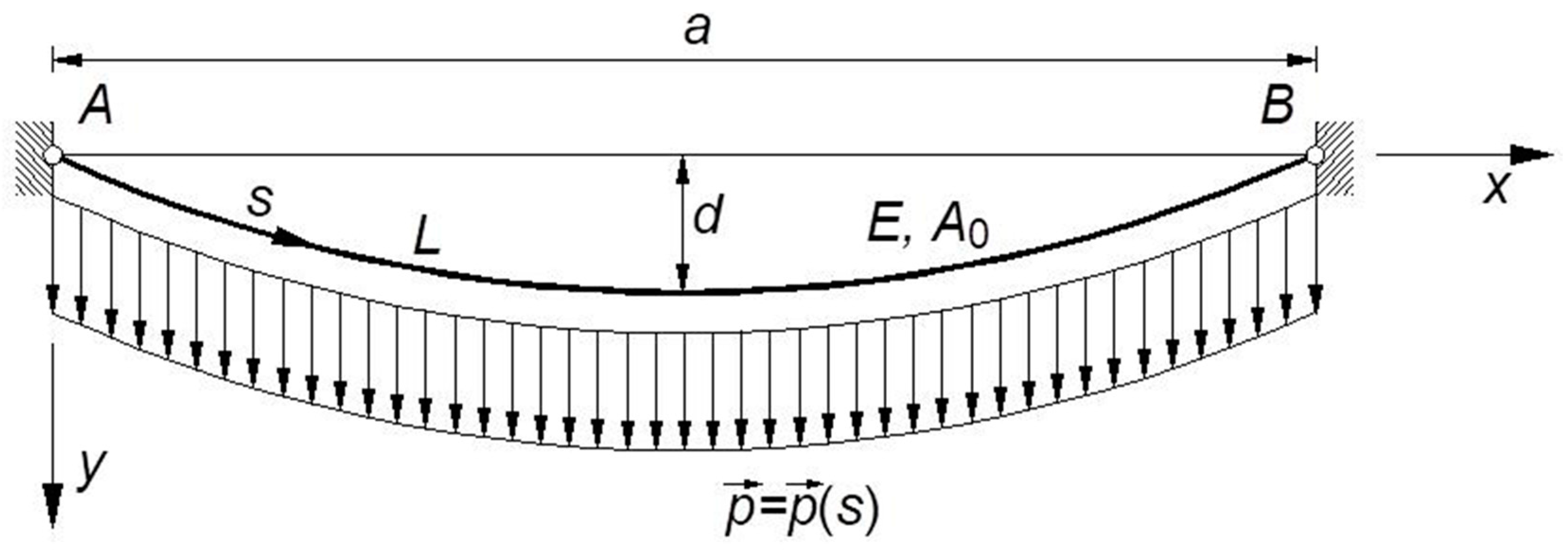
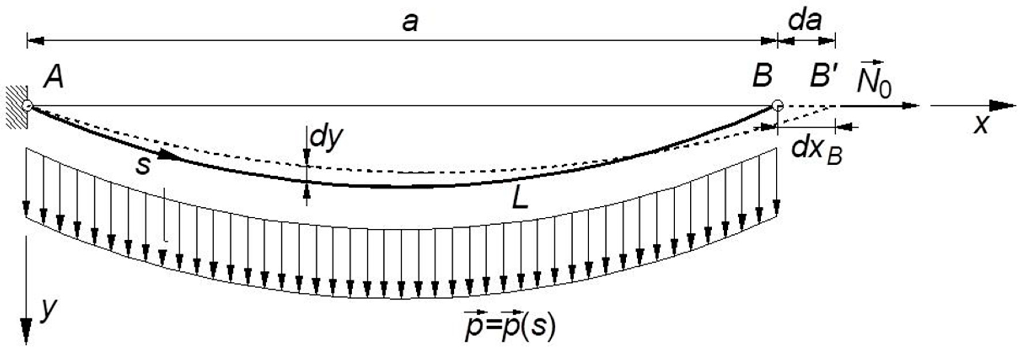
: in fact, the virtual displacement can affect the length of the cable, or the length of the chord. In the former case, which also reproduces the tensioning phase of a real cable, the cable itself is assumed to run over a fixed pulley in
(
Figure 3): in this case, the length of the chord is not affected by the displacement
, which entirely results in a variation
of the cable length
. On the contrary, in the latter case, which represents the most frequent operational condition of a structural cable, the cable extremities are assumed fixed in
and in
: consequently, the displacement
is entirely converted in a variation
of the cable chord (
Figure 4).
Recalling that the cable ordinate
is expressed by Equation (21), in both situations, the expression of the virtual work equation is
where
is the normal stress,
the variation of the longitudinal strain,
the volume of the cable, and
the variation of
caused by the modification of the shape of the cable itself.
Obviously, when the deformations of the cable are disregarded, i.e., the cable is assumed to be inextensible, the left-hand side of Equation (23) is zero.
Since
is negligible with respect to
, and
is parallel to
, Equation (23) can be reduced to
Let
be the abscissa of an arbitrary point of the cable, we can remark that the variation
of the ordinate of that point is the result of the relative displacement component along the cable chord,
, as well as of the variation
of the horizontal component of the axial force. The total variation,
, can be interpreted as the sum of two contributions: one,
, associated with the modification of the shape of the cable, assumed to be inextensible; the other,
, due to the variation of the elastic strain produced by
:
The variation
associated with the configuration change can be obtained by differentiating Equation (25) and considering that, for a given abscissa
,
depends only on
and on
. Consequently,
results:
Obviously, in case the chord length is fixed, i.e.,
a is constant, Equation (26) reduces to:
On the other hand, the variation
due to the elastic strain variation is a function of the vertical component of the axial force only. That contribution can be implicitly taken into account in the expression of the cable’s equation, assuming that the length of the “inextensible” cable is equal to its final, deformed length. The variation of the cable ordinate
can be easily derived recalling that, according to Irvine [
11], the contribution of elastic strain variations to the final configuration of a cable, made with a linear elastic material, is
In fact, differentiating Equation (28) with respect to
,
finally results
It must be underlined that in the present study effects of the elastic deformations are properly considered, being disregarded, as usual, only the effect of the elastic variation of the cable length on the integration limits.
6. Some Relevant Examples
To highlight the refinements achieved by using the proposed approach, the new formula (41) has been applied to evaluate the apparent stiffness
in the relevant case of steel cables, considering chord lengths varying in the range
. According to usual design assumptions, the following values have been adopted for the specific weight and the elastic modulus of the steel cable:
;
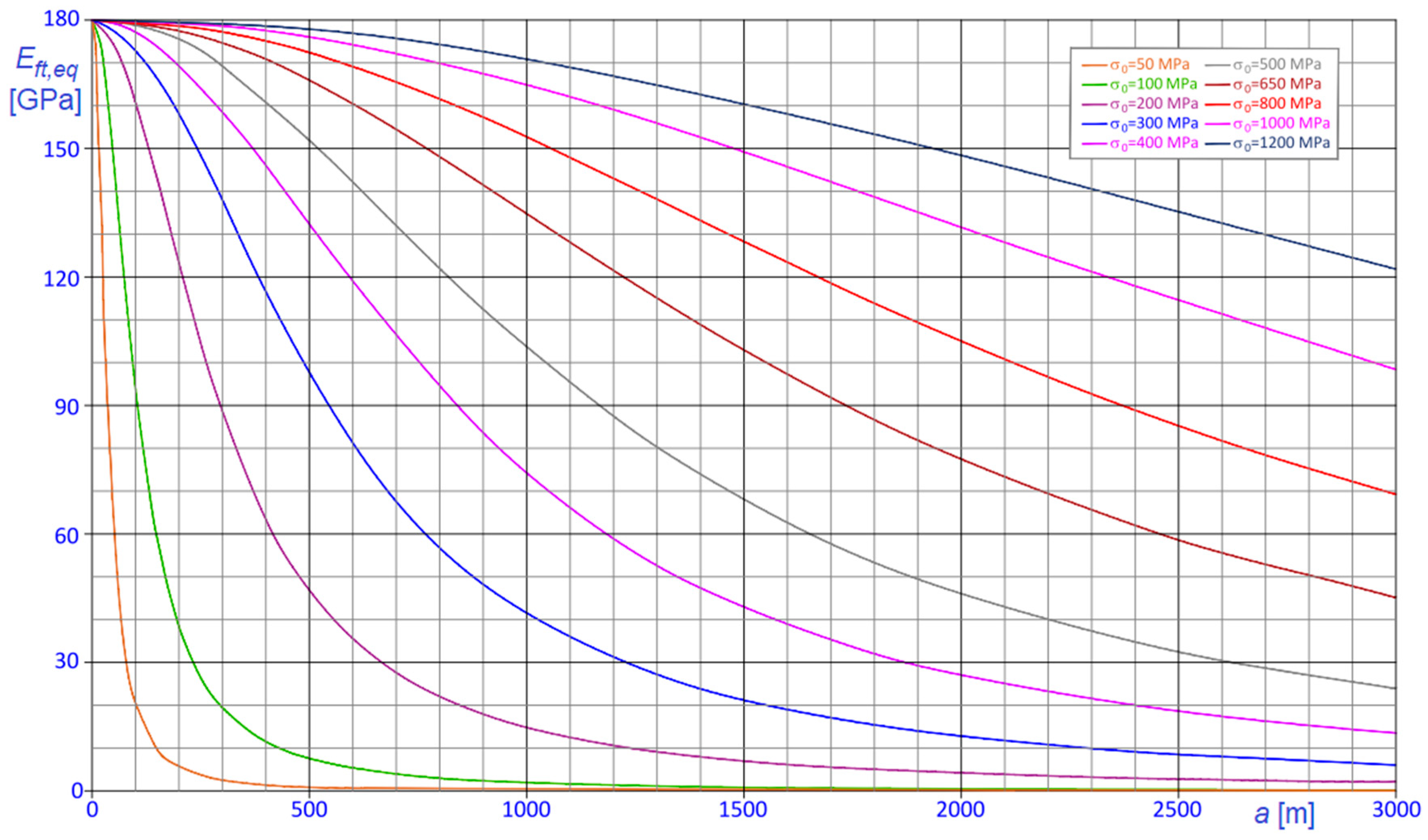
, thus obtaining the results summarized in
Figure 6 and
Figure 7.
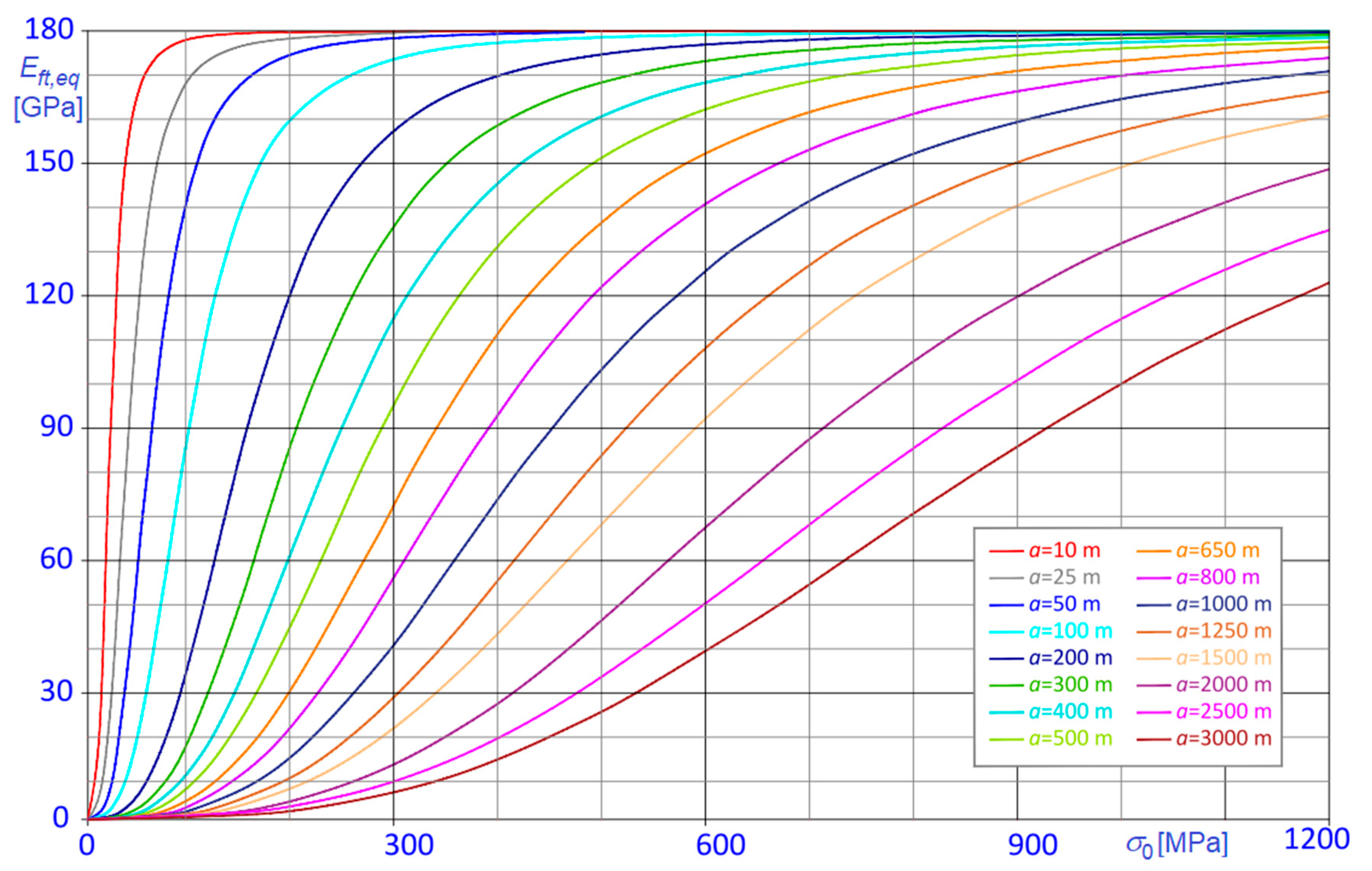
In
Figure 6, the
curves are parameterized in terms of the chord length,
; conversely, in
Figure 7,
curves are parameterized in terms of the horizontal component of the tension,
.
Inspection of the diagrams confirms that, when the stress is low and the chord length is large, the equivalent modulus can be significantly smaller than . Obviously, the effect is further intensified when the cable is running around a fixed pulley.
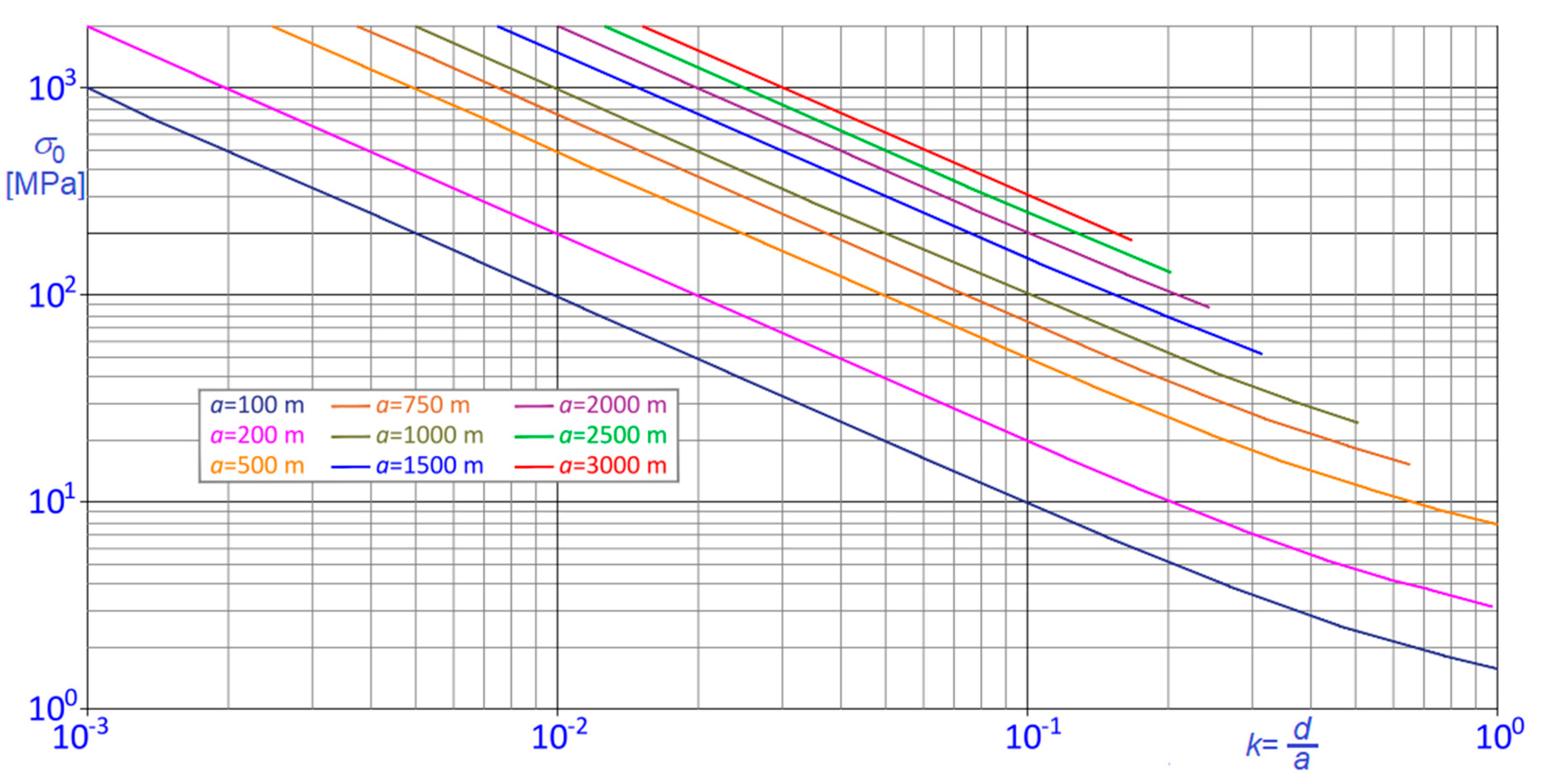
To facilitate the interpretation of the results, given the chord length
, it is useful to associate the value of the stress component
with the corresponding cable sag,
, or, better, with the corresponding sag to chord ratio
, given by
as illustrated in the bi-logarithmic graph of
Figure 8. In
Figure 8, curves have been derived considering that, in practice, upper limits exist for the cable sag
, for example, due to the limited height of the pylons or to the limited elevation of the cable attachments over the roof, over the deck, or over the valley floor. For that reason, in the considered examples, it has been assumed
, implying that
curves are limited on the right and that
is bounded from below.
For instance, in the present case, where , and , the lower limit of , which is about when , increases to about when , to finally attain values around and for and , respectively. Clearly, when cables are made with materials other than steel, lower limits of vary, depending on the specific weight, , of the cable material itself.
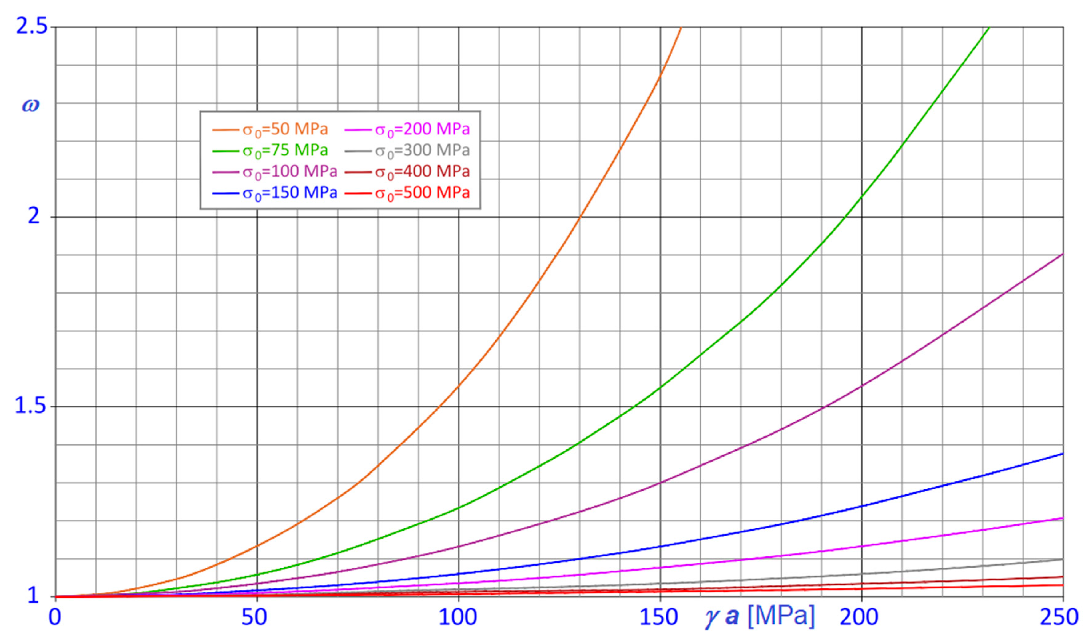
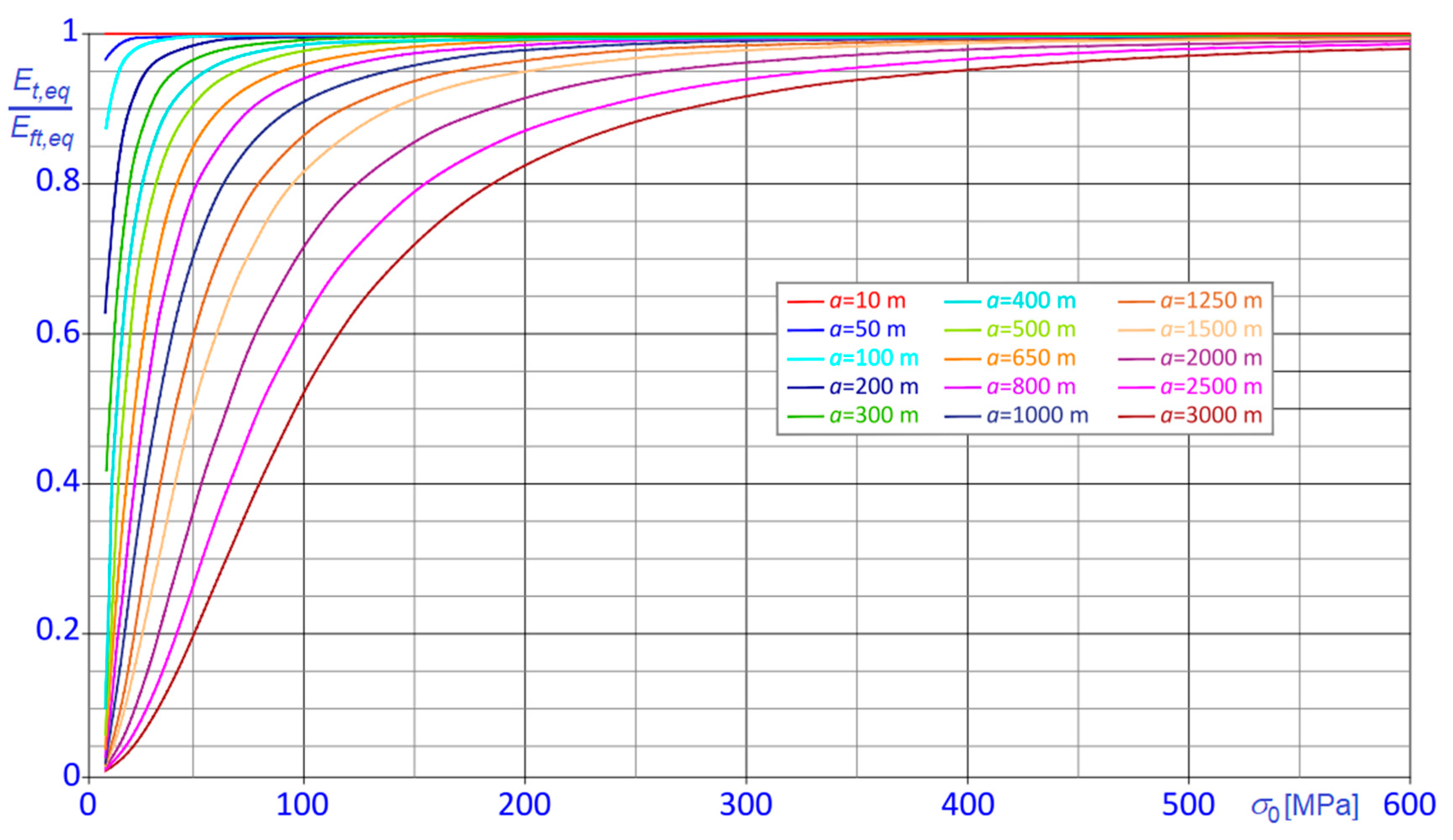
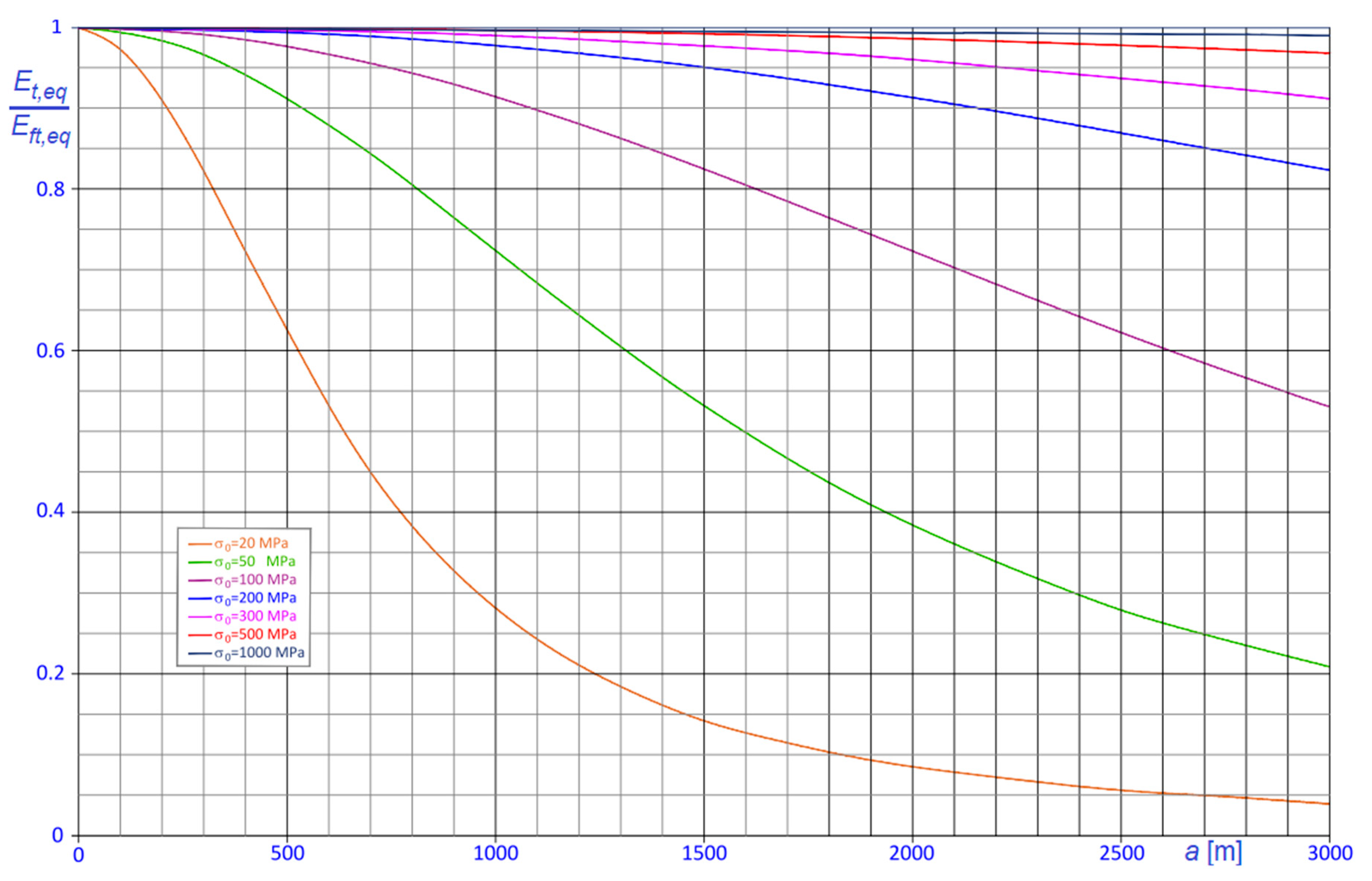
To check the capability of the classical Dischinger’s formula to predict the effective behavior of steel cables, the ratios
between the Dischinger modulus,
(Equation (1)), and that predicted with the proposed formula,
(Equation (41), are plotted against the chord length
and the horizontal stress component
in
Figure 9 and
Figure 10, respectively. Curves are consequently parameterized in terms of
in
Figure 9 and in terms of
in
Figure 10.
The diagrams demonstrate that the equivalent stiffness derived via the classical Dischinger’s formula is regularly lower than the one derived with the formulation proposed here and that the error increases as soon as the stress in the cable decreases, or, evenly, the sag to chord ratio, , increases.
7. Generalization of the Results
Thus far, the results for the steel cables have been discussed. Despite its relevance, this is not the unique significant case that can be met in different fields of current design practice, where the use of many other traditional or innovative structural materials can be more suitable.
A discussion about the applications of these materials is outside the scope of the study, even if cables made with innovative structural materials are increasingly proposed not only for cable-stayed and suspension bridges [
23,
24], but also for general structural applications [
25,
26], as well as in the framework of strengthening, restoration and repair interventions [
27]. Further studies consider hybrid solutions too [
28].
It is known that the efficiency of cables made by different materials can be efficiently compared through two particularly relevant properties: the specific strength, , which is the ratio between the tensile strength and the density of the cable material, and the specific stiffness, which is the ratio between the elastic modulus and the density of the cable material.
For the steel cables, usually it is
and
, so that
and
, while cables made by more modern and advanced materials, like aramid, liquid crystal aromatic polyester (LCP), polybenzoxazole (PBO) or carbon fibers, exhibit more favorable values. Some reference values for mechanical properties of cables made by different artificial, metallic, or biologic materials are reported in
Table 1.
The specific stiffness is related to the magnitude of nonlinear effects on cable behavior. In fact, Equation (39) suggests that, for a given value of , reduces as increases, so that, generally, as higher is the value of the specific stiffness as smaller are the nonlinear effects.
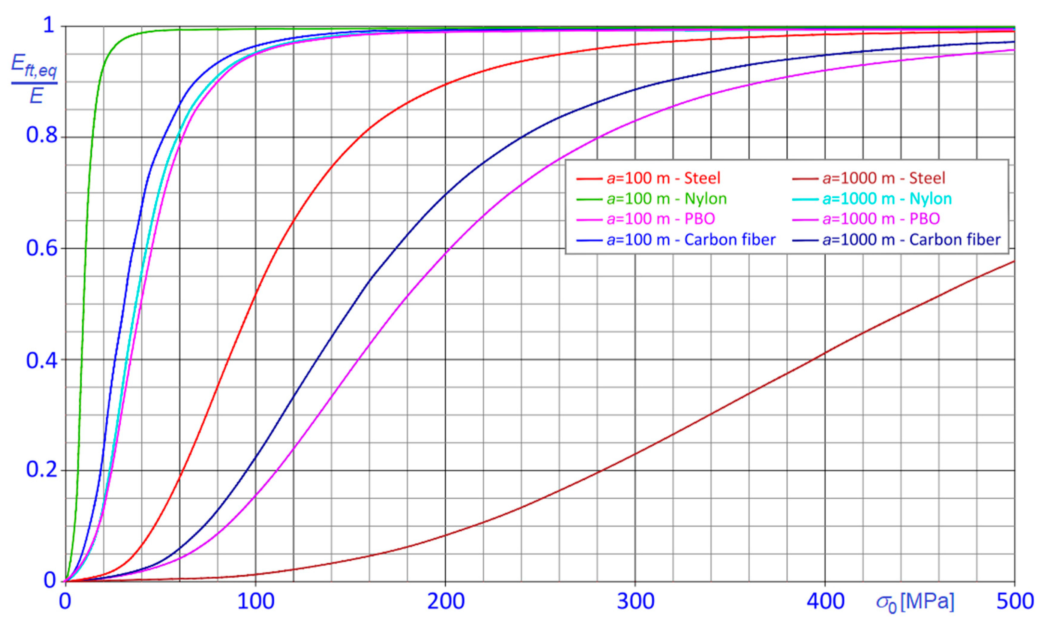
But that conclusion is correct only when the comparison refers to materials with significantly different densities and with comparable elastic moduli, like, for example, steel and PBO or steel and carbon fiber. To better clarify this remark, the
curves, pertaining to cables made by different materials, namely, steel, carbon fiber, PBO and nylon, are compared in
Figure 11, considering two different chord lengths,
and
.
Truly, looking at the curves in
Figure 11, much more articulated and interesting conclusions can be derived about the dependence of the ratio
on the specific stiffness. In fact, considering two cables made with different materials, nonlinear effects are more pronounced in that characterized by bigger specific stiffness only if the densities of the materials are comparable, or the elastic moduli of the materials are considerably different, as it is evident comparing the curves pertaining to of PBO, carbon fiber and nylon cables, or those pertaining to steel and nylon cables in
Figure 11.
That behavior can be explained considering that nonlinear effects are mainly determined by the work made by the self-weight of the cable (see Equation (24)). Once the cable configuration is fixed, the work of the self-weight turns out almost independent on the elastic modulus of the material, so that its influence on is more relevant for materials characterized by smaller modulus, .
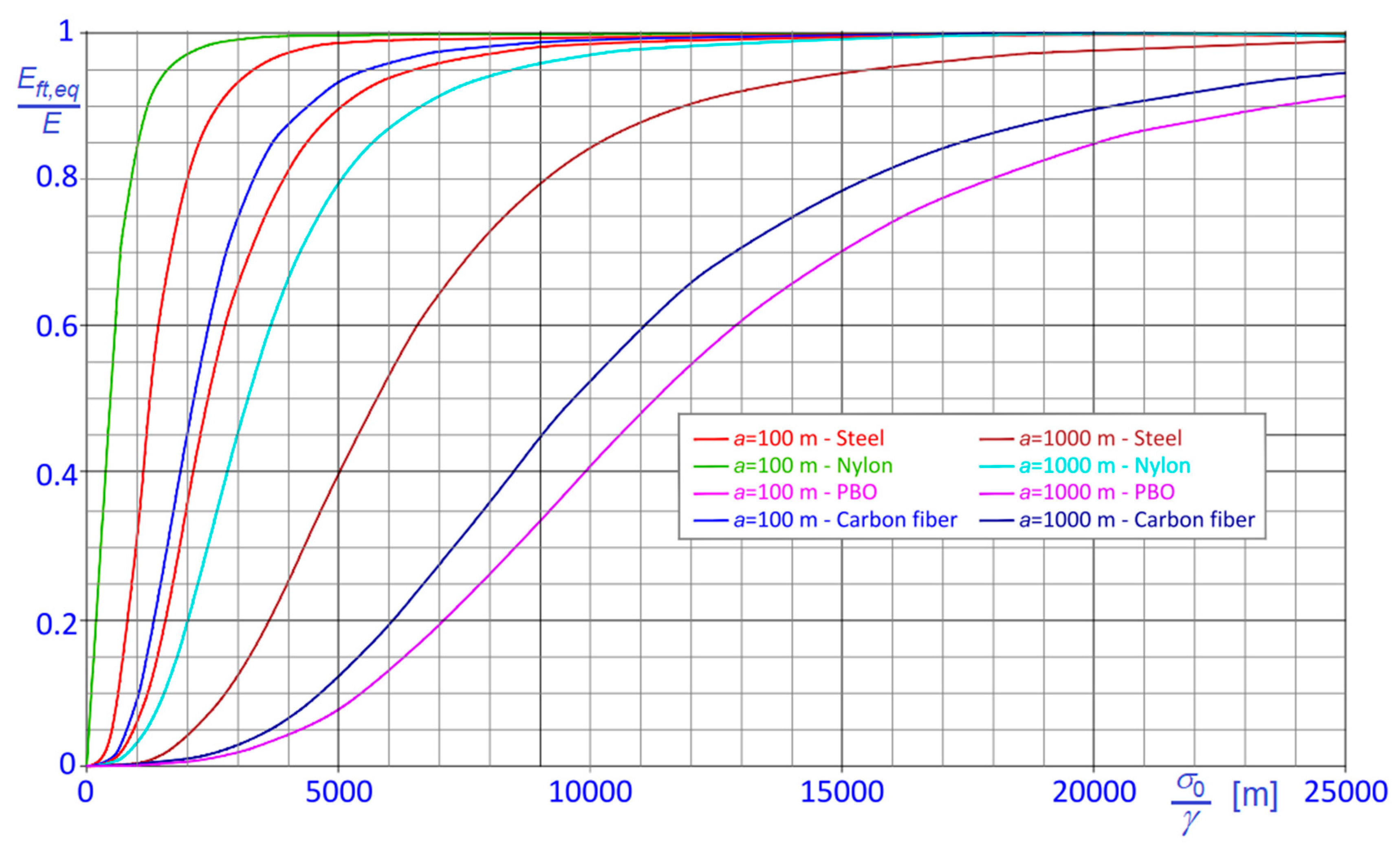
On the other hand, some additional conclusions can be also derived regarding the dependence of the ratio on the ratio , as a function of the cable material.
Recalling Equation (30), it is clear that cables made of different materials, and having the same sag and the same chord length, are associated to the same ratios , or .
In
Figure 12, the
curves for steel, carbon fiber, PBO and nylon cables are diagrammatically shown considering again two different chord lengths,
and
.
From the diagram in
Figure 12, it is evident that, among the considered materials, PBO cables are characterized by the lowest
ratio, while nylon cables are characterized by the highest
ratio, and that
ratio is bigger for steel cables than for carbon fiber cables. Therefore, it is again confirmed that the magnitude of nonlinear effects increases with the specific stiffness of the material only when materials with sensibly different densities and similar elastic moduli are compared; on the contrary, as stated before, comparing materials with similar densities leads to exactly the opposite conclusion.
It must be stressed that the comparisons discussed above are devoted to point out the effects of the variation of elastic modulus and density of various materials on the extent of nonlinear behavior of the cable, independently on the mechanical or economic feasibility of the solutions which are envisaged here. For additional information, see, for example, [
23].
We underline that the proposed formulae maintain their validity also when long term effects are significant, like for creep-sensitive materials, provided that the pertinent time dependent creep coefficient is known [
29], and that the Young modulus of the material is replaced with the appropriate age-adjusted effective elastic modulus.
8. Conclusions
The nonlinear behavior of horizontal cables under the self-weight is the subject of a number of studies, often aiming to find suitable expressions for the equivalent along the chord stiffness.
The topic is very relevant in view of practical applications, as the results allow important simplifications of nonlinear analysis of cable structures. For example, in finite element analysis (FEA), replacing the cables or parts of them with suitable equivalent nonlinear spring or truss elements considerably increase the speed and the efficiency of the analysis. On the other hand, the knowledge of the equivalent stiffness can be a robust practical tool to rapidly check results of nonlinear FEA.
Several simplified formulae have been proposed over the years, starting from the classical expression proposed by Dischinger, still frequently used in current design practice, and arriving to much more refined solutions, like that due to Irvine.
In a previous study, starting from the classical Bernoulli equation of the catenary, and applying the virtual work theorem, accurate and general expressions of the along the chord tangent stiffness of inclined cables subject to the self-weight were derived, as a function the nature of the relative displacement of the cable extremities. Depending on the boundary conditions of the stay, two relevant situations can occur, corresponding to distinct solutions: in fact, it could happen that both ends of the cable are attached, like in normal working conditions, so that the unstrained length of the cable is fixed; or, alternatively, that one end is fixed and the other is running around a fixed pulley, like in the cable tensioning phase, when the unstrained length of the cable varies as a function of the applied tensile force. The study demonstrates that the equivalent stiffness of the cable in the former case is bigger than in the latter. It must be underlined that not only classical simplified formulae, but also more refined approaches proposed over the years, are unable to make such a fine distinction, depending on the restraints at the stay ends.
The abovementioned innovative general closed form solutions, suitable to be used in modeling equivalent spring or truss elements, are also valid for horizontal cables, but they are so complex and the calculations so complicated, that their reduction to that particular case was not easy.
For that reason, the above-recalled method has been applied to directly deduce the equations of the equivalent stiffness of horizontal stays.
The outcomes of the procedure are new expressions of the equivalent tangent modulus of the horizontal cable, depending on the nature of the boundary conditions. As they accurately consider all influencing parameters, these rather compact innovative formulae can be again applied without restrictions, independently on the inclination of the cable, on the sag of the catenary, and on the cable material, thus allowing a generalized application of the equivalent stiffness approach, in particular in the low stress region. Of course, the formulae given here for horizontal cables, which can be also applied for slightly inclined cables, coincide with those derived from the expressions for inclined cables when tends to zero.
A relevant case study, involving horizontal steel stays with fixed ends, and chord length varying in the range , is discussed in detail, also aiming to estimate the approximations inherent with the Dischinger’s approach. The outcome is that Dischinger’s formula underestimates the actual stiffness of the cable, especially when the value of the horizontal component of the stress is small.
Results have been extended to other significant cases, taking into account various natural or artificial cable materials, so highlighting that the magnitude of nonlinear effects in the cable depends not only on the specific stiffness, but also on the elastic modulus and on the density of the material.
Long terms effects can be also taken into account, provided that the elastic modulus of the material is replaced with the pertinent age-adjusted effective modulus.
Moreover, in case the cable is inhomogeneous, there are relevant situations where the proposed formulae can be applied without modifications, like in case of a hybrid cable; or in case the cable is obtained connecting two or more stretches made of different materials, on condition that specific weight and elastic modulus of distinct stretches are comparable, but, evidently, the latter case seems quite unrealistic.
Depending on the particular structure under consideration, other relevant cases can be envisaged in the practice: for example, in cable-stayed bridges or in other guyed structures, where the main distributed load acting on the stay is mainly the self-weight of the stay itself, the reference configuration to be considered for the cables s the catenary; while, in suspension bridges or in other structures characterized by horizontal and inclined cables sustaining uniformly distributed loads, the reference configuration to be considered for the cable is the parabola.
The proposed solutions for horizontal stays, together with the general expressions already found for inclined stays, provide a complete and original set of formulae for the evaluation of the equivalent stiffness of stays.
Evidently, according to an approach frequently adopted in the existing studies, it is possible to use these expressions also in case of loaded cables, suitably increasing the unit self-weight of the cable in order to simulate the presence of the uniformly distributed load, i.e., fitting the actual deformed parabolic shape, with the appropriate catenary.
Although reasonable for taut cables, that approximation becomes unacceptable as soon as the cable sag increases, and the parabola significantly deviates from the catenary. Further studies will be thus addressed to natural improvements of the proposed approach, aiming to arrive to general solutions also for uniformly loaded cables, hypothesizing parabolic deformed configurations.
In addition, other promising extensions can be also envisaged, aiming to encompass, when relevant, the bending stiffness, and the shear stiffness of the cable as well.
