Article

Appropriate Matching Locations of Rail Expansion Regulator and Fixed Bearing of Continuous Beam Considering the Temperature Change of Bridge

1
School of Civil Engineering, Central South University, 22 Shao-shan-nan Road, Changsha 410075, China
2
Key Laboratory of Heavy Railway Engineering Structure of Education Ministry, Railway Campus, Central South University, 22 Shao-shan-nan Road, Changsha 410075, China
*
Author to whom correspondence should be addressed.
Appl. Sci. 2020, 10(17), 6046; https://doi.org/10.3390/app10176046
Submission received: 10 August 2020 / Accepted: 31 August 2020 / Published: 31 August 2020
(This article belongs to the Special Issue Interactions between Railway Subsystems)

Abstract

:
Due to the temperature change of bridges, there is a great additional force in continuously welded rails on continuous bridges. Laying rail expansion regulators is an effective measure to reduce the additional force. The nonlinear finite element model is presented for a continuously welded rail track with a rail expansion regulator resting on the embankment and simple and continuous beams, considering the temperature change of the bridge. Then, a method is proposed to determine the locations of the rail expansion regulator and the fixed bearing of the continuous beam, corresponding to the maximum additional forces of rail reaching minimum values. Their appropriate matching locations are recommended based on the obtained influence laws of any locations of the rail expansion regulator and the fixed bearing of the continuous beam on the maximum additional forces of rail. The results can provide the theoretical basis for the design of the rail expansion regulator and the fixed bearing of long-span continuous bridges.

1. Introduction

Continuously welded rails (CWRs) have been widely used because of their low maintenance cost and good smoothness. However, there is a great additional force in continuously welded rails on a continuous bridge due to the temperature change of the bridge, which may cause the rail to buckle or break. Therefore, the thermal interaction between rail and bridge has been the subject of scientific studies [1,2,3,4]. Many scholars have paid more and more attention to the thermal interaction between CWR and railway bridges and analyzed the influencing factors and laws of the additional forces of rail. Based on the longitudinal linear stiffness between rail and bridge, Frýba [1] and Esveld [2] presented analytic solutions of the additional thermal force of CWR on simply or continuously supported bridges. Chen et al. [5] established a mechanical model of interaction between CWR and arch bridges. Ruge et al. [6,7] pointed out the importance of rail deformation history and the influence of track–bridge temperature changes on rail deformation history and studied the track–bridge thermal interaction considering nonlinear characteristics. Ryjacek and Vokac [8] determined the stiffness value of the connection between track and bridge and its nonlinear variation law. Zhang et al. [9,10] established a nonlinear track–bridge interaction analysis framework that considers the load history effect. Alfred et al. [11] established a nonlinear finite element model of track–bridge interaction that considers the thermal expansion of the structure. Dai et al. [12] proposed an analytical algorithm based on the bilinear resistance model to analyze the track–bridge thermal interaction. Yun et al. [13] analyzed the influence of temperature changes on the track–bridge interaction through field tests.
Based on the study of rail–bridge thermal interaction, some scholars have researched the influence of different factors on the additional force of rail and discussed methods to reduce the additional force of rail. Dai and Liu [14] analyzed the influence of different fasteners on the additional force of rail. Liu et al. [15] investigated the effects of ballast resistance, the friction of movable bearings, and the location of the rail expansion regulator (RER) on rail stresses under seismic action. Cai et al. [16] established the spatial coupling model of CWR on the background of the An-Jiu railway super large cable-stayed bridge and optimized the position of the rail expansion regulator. Ramos et al. [17] performed a parameter study of prestressed concrete continuous girder railway bridges, designed with European standards, by means of nonlinear finite element analysis. Yan et al. [18] found that installing RER at the end of the bridge can effectively reduce the additional expansion force of rail. Lou et al. [19] considered the longitudinal nonlinear stiffness characteristics and studied the influence of some factors on the additional stress of rail. Liu et al. [20] studied the influence of the support of a long-span steel bridge on the additional expansion force of rail. Yu et al. [21] discussed the influence of a simply supported beam-support arrangement on the rail longitudinal force. Wenner et al. [22] carried out long-term monitoring of additional force of rail and explored the influence of temperature on the additional force of rail. Mirza et al. [23,24] used the finite element software ABAQUS to study the mechanical properties of rail–bridge systems under the action of thermal load and different levels of seismic load. Choi et al. [25] considered setting a low-friction sliding layer between the track and the bridge to reduce the additional forces of rail caused by the temperature change of the track and the bridge.
The longer the bridge is, the greater the maximum additional force of rail is. Laying RER is an effective measure to reduce the additional force of rail; Figure 1 shows the photo of RER laid on site. Some scholars [15,16,17,18] have pointed out that the location of RER is an important factor affecting the additional force of rail. The authors find that the locations of the fixed bearing of the continuous beam are also an important factor. In particular, the matching of the RER location and the fixed support location of the continuous bridge has a significant effect on the maximum additional force of rail. To the authors’ knowledge, research on the appropriate matching locations of the rail expansion regulator and the fixed bearing of the continuous beam is rare. Therefore, it is necessary to investigate the influence laws of any location of RER and the fixed bearing within the range of the continuous beam on the maximum additional forces of rail, and then put forward to their appropriate matching locations. Compared with the existing literature, the innovations of this paper are to propose the method to determine the locations of the rail expansion regulator and the fixed bearing of the continuous beam, corresponding to the maximum additional forces of rail reaching minimum values, and to recommend their appropriate matching locations. In addition, this paper finds that during the temperature rise of the beam, there is an upper limit value of additional tension force of rail but no lower limit value of additional compression force; when the temperature falls, the result just reverses. The obtained results can provide a theoretical basis for the design of the RER location and the fixed bearing location of a long-span continuous bridge.

2. Model

Figure 2 shows a schematic planar model of a CWR track with RER resting on multiple span simple beams, one continuous beam, multiple span simple beams, and two approach embankments, in which L s represents the length of the simple beam, L c represents the length of the continuous beam, L 0 represents the distance between the two fixed bearings of the simple beam neighbor to the continuous beam, l fb represents the distance between the fixed bearing of the continuous beam and that of the simple beam neighbor to the left side of the continuous beam, o c represents the midpoint of the continuous beam, o 0 represents the midpoint of L 0 , and SB and CB represent the simple and continuous beams, respectively. The continuous beam has only one fixed bearing, and the fixed and movable bearings of simple beams on two sides of the continuous beam are arranged alternately from left to right. It is assumed that the rightward longitudinal displacement, additional tension force in rail, and the temperature rise of the beams are taken as positive. In order to find the appropriate locations of RER and the fixed bearing, RER and fixed support can be anywhere in the range of the continuous beam in the numerical simulation.
With CWRs, simple and continuous beams are modeled as beam elements. The rail at RER is simulated as disconnected without constraining its longitudinal displacement, and its additional force is zero. The track components between rails and bridge, including fasteners, sleepers, and bed, are modeled as coupling shear elements with nonlinear stiffness, as shown in Figure 3. The rail–beam thermal interaction descriptions can be found in [6,7,19]. To facilitate the reading, the main contents are listed here. The nonlinear characteristic of the difference u D of the coupling element depends on the critical value u ˜ [6,7].
u D = { u R u B for | u R u B | < u ˜ u ˜ sign ( u R u B ) for | u R u B | u ˜
where, u R and u B represent the longitudinal displacements of the rail and the upper surface of the beam, respectively, u D represents the displacement difference between u R and u B , and u ˜ represents the critical value of displacement difference in elastic and plastic phases. It is assumed that the simple and continuous beams are not influenced by the rails during the temperature change of the beams and that they can move freely. The value of u B of the simple and continuous beams can be written as (Refernce [1]).
u B = α B Δ T x B
where α B represents the coefficient of thermal extension of the beam, Δ T represents the temperature change with reference to the initial temperature of the beam, and x B represents the distance between the calculated section and the fixed bearing of the beam.
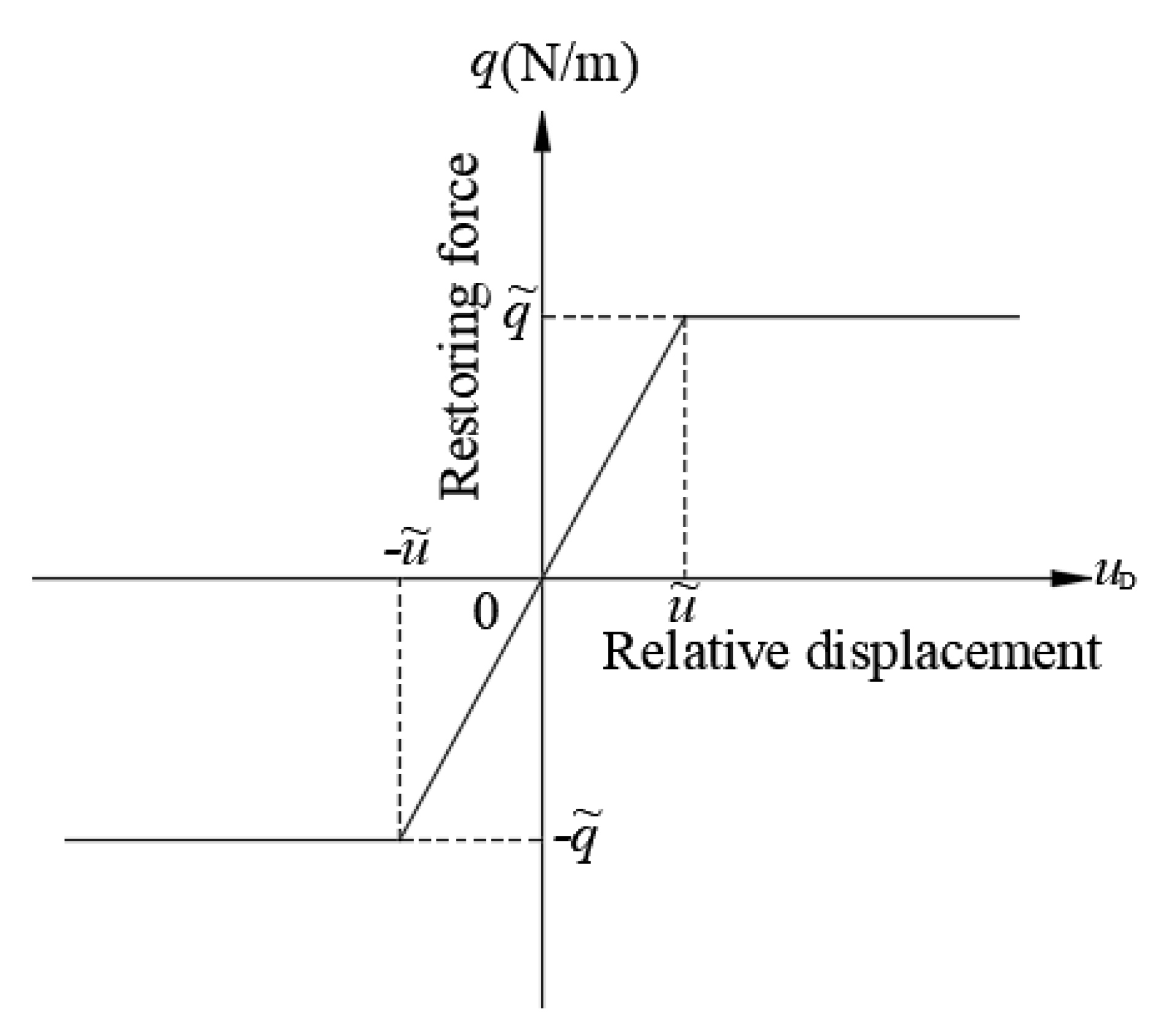
If the absolute value of displacement difference u D is less than this critical value u ˜ , there is a linear relationship between the difference u D and the longitudinal restoring force q , as shown in Figure 4, they can be expressed as (Refernces [6,7])
q = c u D f o r | u D | < u ˜
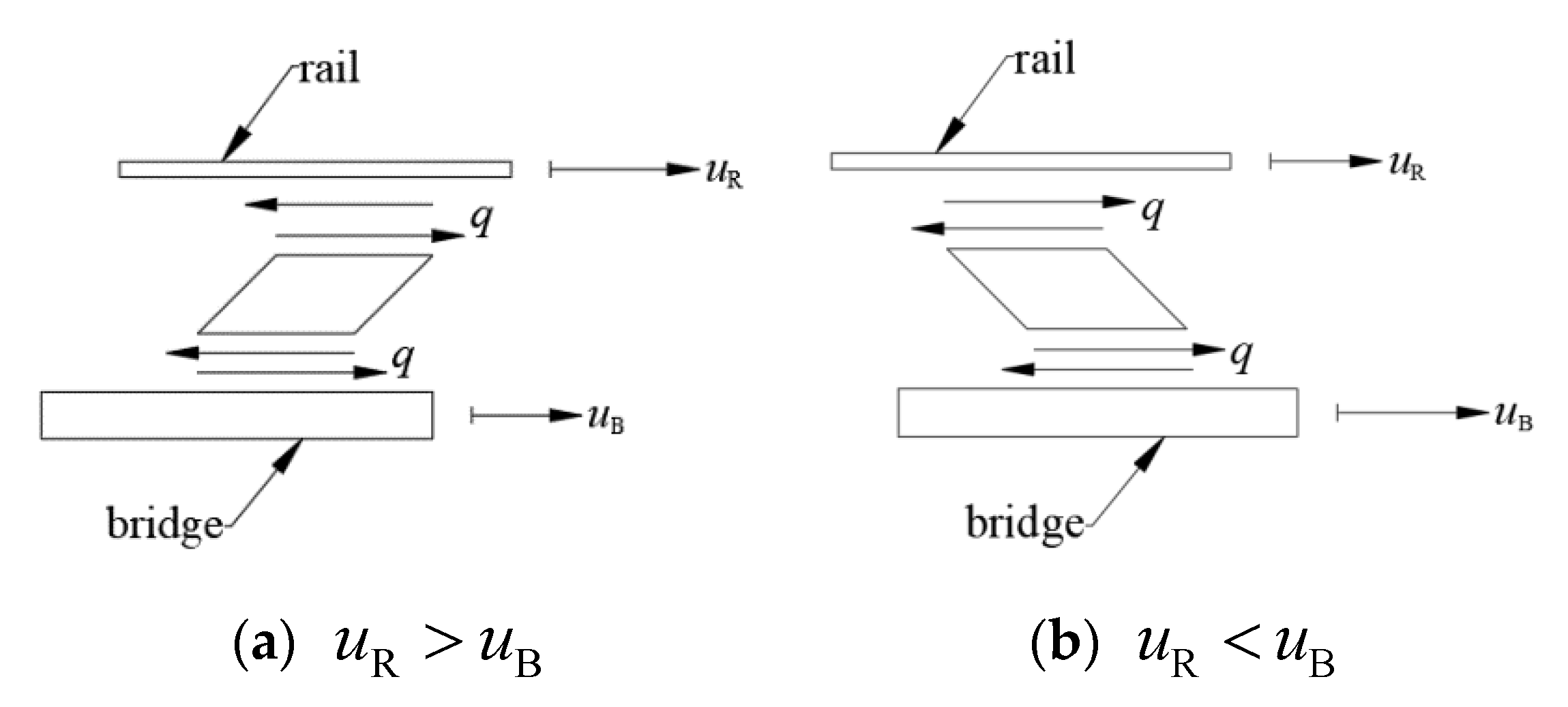
in which c represents spring stiffness per unit length in the linear phase; if u D > 0 , a force q with negative value acts on the rail, consequently, a force q with positive value acts on the bridge; if u D < 0 , the forces q acting on the rail and the bridge are just opposite to those above.
If the absolute value of difference u D is not less than the critical value u ˜ , the rail slips, relative to its base. The nonlinear relationship in Figure 4 is applied, and the longitudinal restoring force q is a constant q ˜ , with (Refernces [6,7])
q = q ˜ = c u ˜ sign ( u R u B ) f o r | u R u B | u ˜
The track components connecting the rails with the embankment are modelled as longitudinal springs with nonlinear stiffness, as shown in Figure 4. Since the longitudinal displacement of the embankment can be ignored, the relationships between q and u D can be obtained by Equations (3) and (4), with u B replaced by zero.
The whole-mechanics equation for CWR with RER on bridges and embankment can be expressed as (Refernce [19])
K U = F
where K represents the whole-stiffness matrix, and U and F represent the whole displacement and load vectors, respectively. The computer program is compiled to solve Equation (5) and obtain the responses of rail with RER and the fixed bearing of the continuous beam at any location.

3. Verification

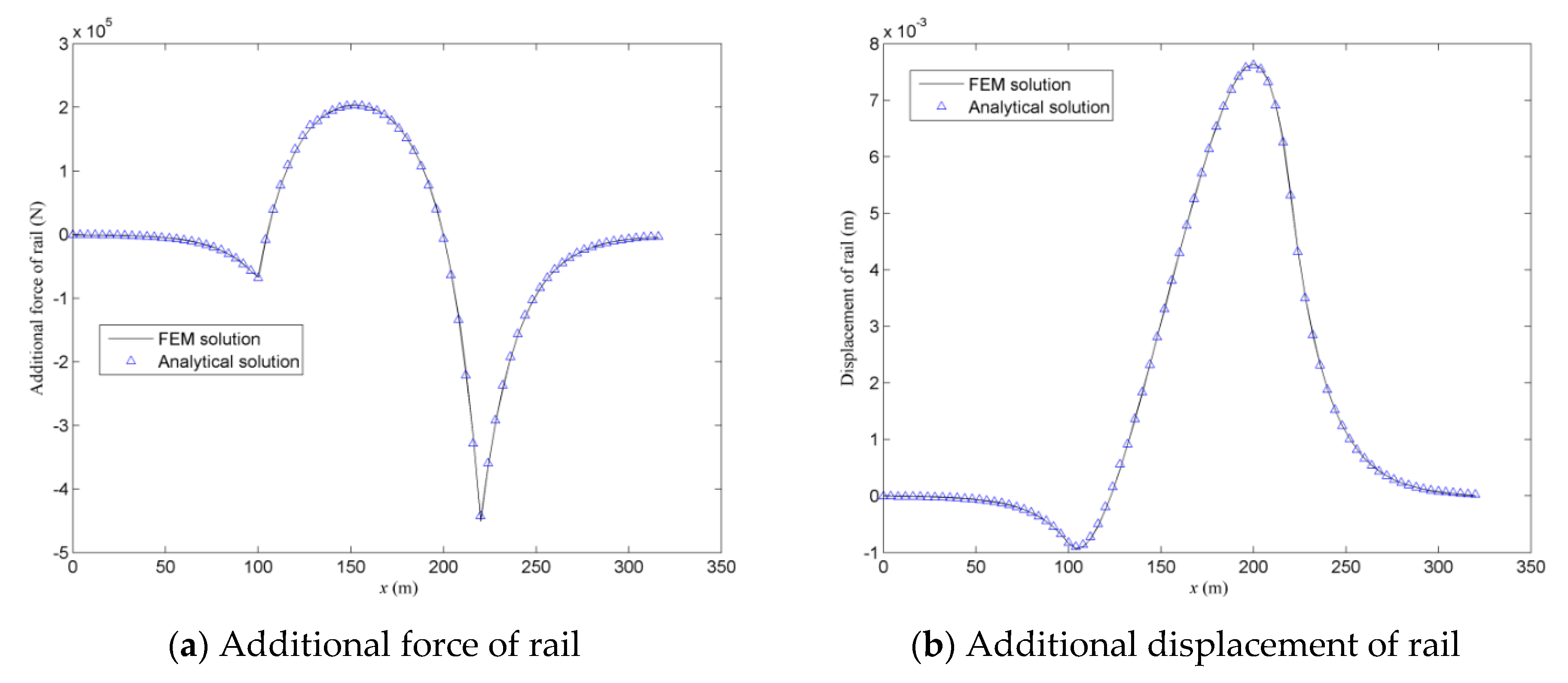
A CWR track is considered on a single continuous beam and two approach embankments. The parameters are listed in Table 1 from the Chinese code [26], except for the parameters of L c and L E . The spring stiffness per unit length and per rail are the same with 4.4 × 10⁶ N/m2/rail on the embankment and on the bridge. The fixed bearing is assumed to be located at 30 m away from the left end of the continuous beam; thus, the distance is 90 m between the fixed bearing and the right end of the continuous beam. It should be mentioned that the four parameters of u ˜ B , q ˜ B , u ˜ E , and q ˜ E in Table 1 are not adopted in this section, but used in Section 5. In order to use the self-compiled program to calculate the additional force and displacement on the rail, the number of simple beams is set as zero. Figure 5 plots the distributions of the additional displacement and force of rail along its length, induced by the temperature change of the beam by present finite element method (FEM) solutions and analytical solutions [1], in which, the abscissa indicates the distance between a certain section and the left end of the rail. Figure 5 shows that the present FEM solutions are in good agreement with the analytical solutions. Therefore, the proposed model and the compiled program can be effective.

4. Procedures for Determining the Appropriate Locations of RER and the Fixed Bearing of the Continuous Beam

The maximum additional tension and compression forces of rail vary with the locations of RER and the fixed bearing of the continuous beam. Their appropriate locations can reduce the maximum additional force. The procedures are as follows for determining their locations, corresponding to the maximum additional tension and compression forces of rail reaching their minimum values.
(1)
RER is located above the left end of the continuous beam.
(2)
The fixed bearing is also located at the left end of the continuous beam. Then, the additional force of rail along its length is calculated, and the maximum values of the tension and compression forces are obtained. It should be noted that the maximum and minimum values of the compression force refer to the absolute values, the same below.
(3)
The RER location remains unchanged. The fixed bearing location is changed from left to right before arriving at the right end of the beam, and the changing interval may be adopted as one beam element length.
(4)
The maximum additional tension and compression forces of rail are obtained corresponding to each location of the fixed bearing, and the curves of these forces are gained with the change of the location of the fixed bearing.
(5)
The minimum values in the above curves are those of the maximum additional tension and compression forces of rail when RER is located above the left end of the continuous beam.
(6)
The RER location changes from the left to right before arriving at the right end of the beam, and the changing interval also may be adopted as one beam element length. The minimum values of the maximum additional tension and compression forces of rail corresponding to each location of the RER are obtained by repeating Steps (2)–(4).
(7)
The curves of the minimum values mentioned in Step (6), with the change of the location of RER, are drawn. The abscissas corresponding to the minimum values in the curves are the locations of RER to be determined.
(8)
The RER location determined above remains unchanged. According to Steps (3) and (4), the curves of the maximum additional tension and compression forces of rail, with the change of the location of the fixed bearing, can be obtained. The abscissas corresponding to the minimum value in the curves are the locations of the fixed bearing to be determined.

5. Examples

The nonlinear finite element model in Figure 2 is taken into account. On each side of the continuous beam, 5 simple beams are arranged, each with the length of 32 m, which is widely used on site. Unless otherwise specified, the number of simple beams remains unchanged. The adopted value of L c will be specified in the following subsection. Except for the parameter c , the other parameters in Table 1 are used in this section. The appropriate locations of RER above the continuous beam are studied, corresponding to the minimum values of the maximum additional tension and compression forces of rail, and then that of the fixed bearing of the continuous beam is investigated, matching the appropriate location of RER. It should be noted that the following results are based on the temperature rise of 15 °C of the beam. If the changed temperature is −15 °C, then the positive and negative signs, i.e., the tension and compression, will be reversed.

5.1. Appropriate Location of RER

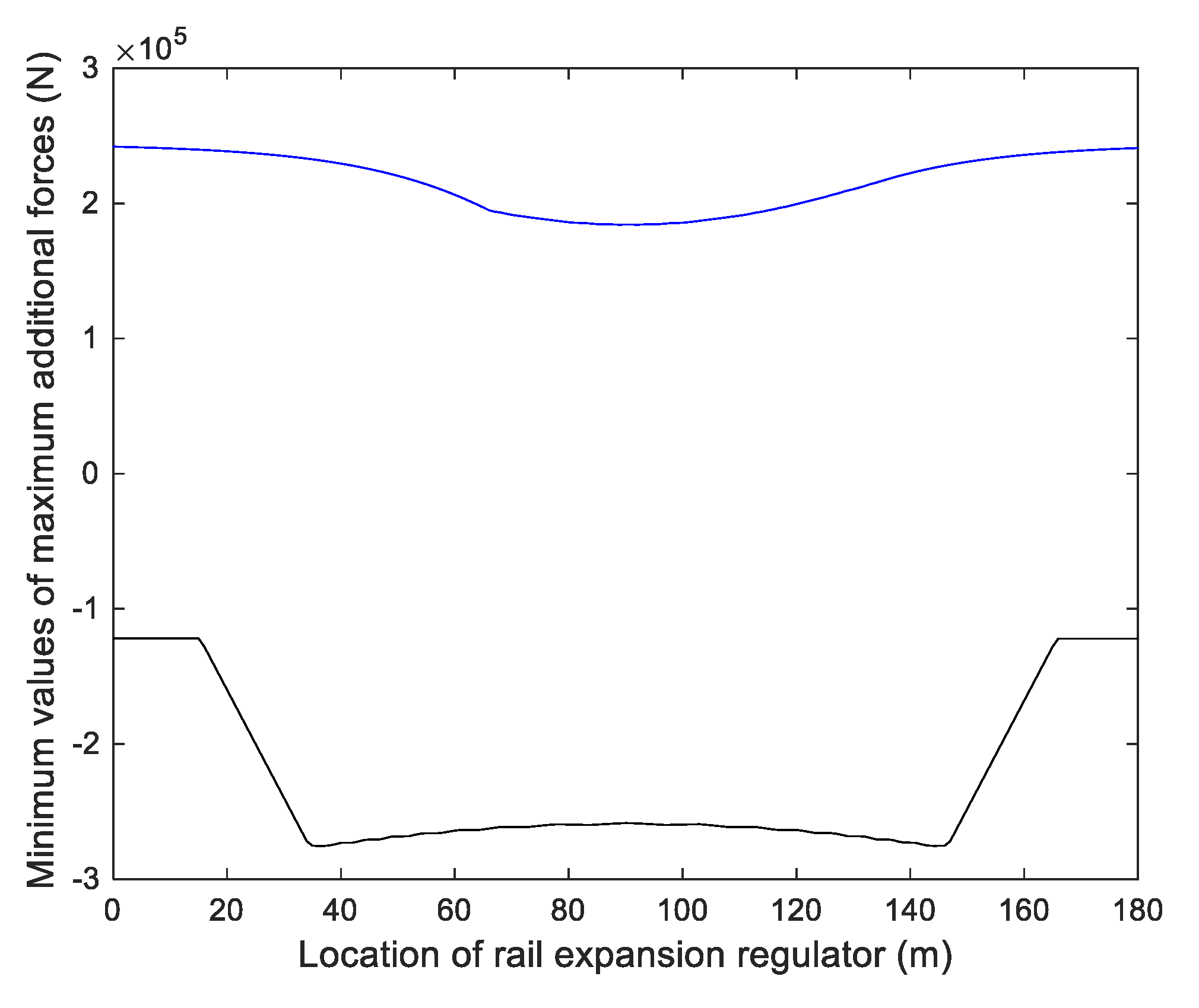
One continuous beam with the length of 180 m is considered as an example to analyze the effect of the location of RER on the minimum values of the maximum additional tension and compression forces of rail. Using Steps (1)–(7) in Section 4, the curves of the minimum values of the maximum additional tension and compression forces of rail, changing with the locations of RER, have been obtained and plotted in Figure 6, in which the abscissa in the figure represents the distance between RER and the rail section above the left end of the continuous beam. As shown in Figure 6, the location of RER has an effect on the minimum value of the maximum additional tension force, with the difference of 31.37% for the two extreme values of 1.8417 × 10⁵ and 2.4195 × 10⁵ N. However, the effect on the minimum value of the maximum additional compression force is more significant, with the difference of 125.85% for the two extreme values of −1.2195 × 10⁵ and −2.7542 × 10⁵ N. RER is arranged above the end and the middle of the beam, which has the opposite effect on the minimum value of the maximum additional compression and tension forces of rail. For the former, the minimum compression force of rail is −1.2195 × 10⁵ N, but the tension force of rail is very large, with the value of 2.4195 × 10⁵ N. For the latter, the minimum tension force of rail is 1.8417 × 10⁵ N, but that of the compression force of rail is very large, with the value of −2.5877 × 10⁵ N. As shown in Figure 6, both cases of u ˜ B and q ˜ B show that RER should be arranged above the two ends and the middle of beam to reduce the maximum additional compression and tension forces of rail, respectively.
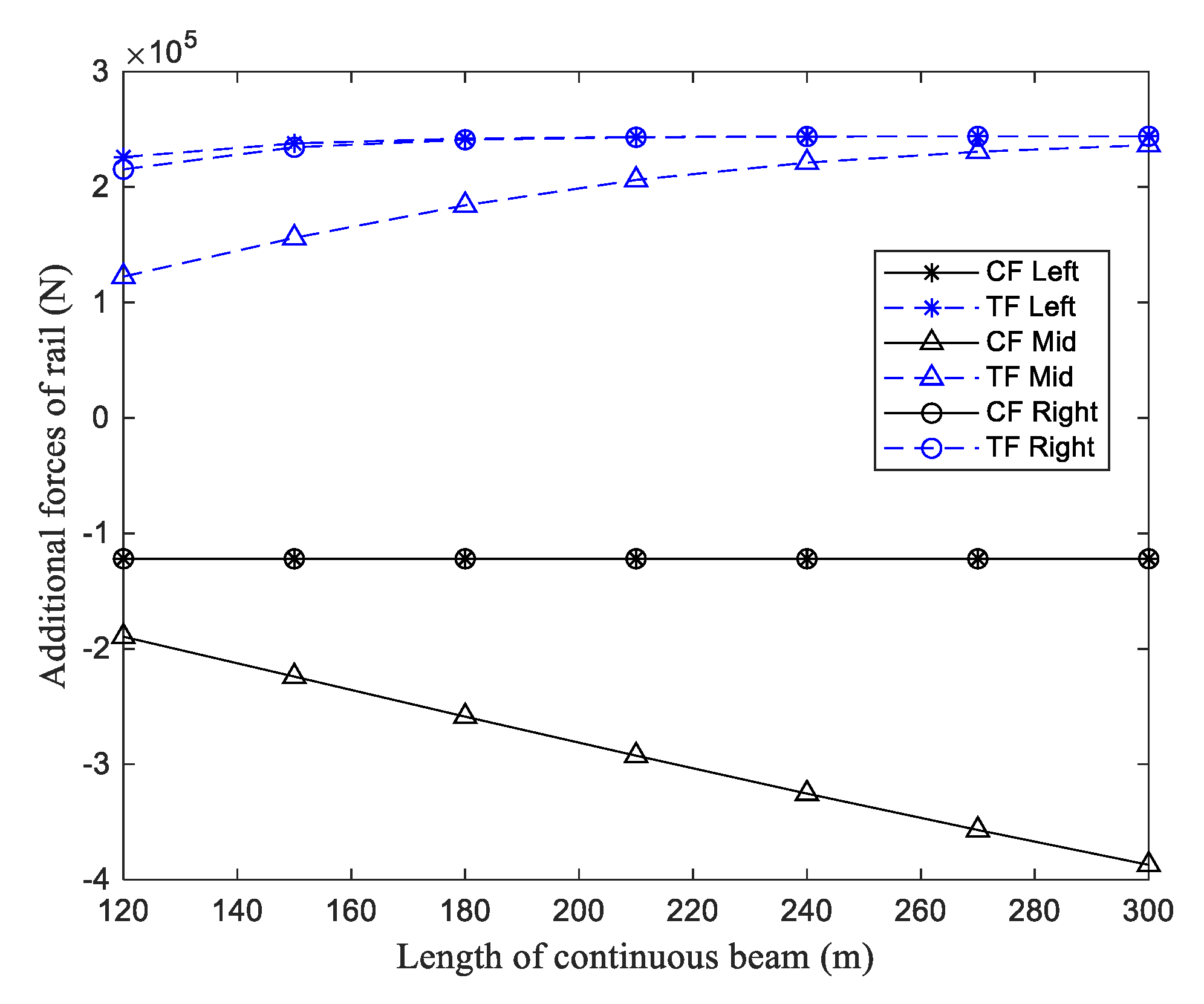
The aforementioned studies show that the appropriate locations of RER are above the two ends and the middle of the continuous beam. For the case of RER located at three positions, i.e., above the left end, the middle, and the right end of the continuous beam, the effects of the lengths of the continuous beam on the minimum values of the maximum additional compression and tension forces of rail are studied. Besides 180 m, lengths of 120–300 m, with intervals of 30 m, are taken into account. Their relationship curves are drawn in Figure 7; RER is arranged above the two ends of the continuous beam, the minimum values of the maximum additional compression forces of rail do not change with the length of the continuous beam, and the minimum values of the maximum additional tension forces of rail increase with the length of the continuous beam, but the increase values are small. For example, the values in the curve of “TF Left” are 2.2595 × 10⁵ and 2.4395 × 10⁵ N, corresponding to the lengths of 120 and 300 m, respectively, with the increase of 7.67%, and the values in the curve of “TF Right” are 2.1534 × 10⁵ and 2.4394 × 10⁵ N, corresponding to the lengths of 120 and 300 m, respectively, with the increase of 13.28%. However, when RER is arranged above the middle of the continuous beam, the minimum values of the maximum additional tension and compression forces of rail change obviously with the length of the continuous beam; in particular, the latter increases significantly. For instance, the values in the curve of “TF Mid” are 1.2242 × 10⁵ and 2.3626 × 10⁵ N, corresponding to the lengths of 120 and 300 m, respectively, with the increase of 92.99%, and the values in the curve of “CF Mid” are −1.8952 × 10⁵ and −3.8716 × 10⁵ N, corresponding to the lengths of 120 and 300 m, respectively, with the increase of 104.28%.
One can conclude that for the continuous beam with the shorter length, RER should be arranged in the middle of the beam, while for the longer length, RER should be arranged at the two ends of the beam, which is conducive to reducing the maximum additional force of rail. As shown in Figure 7, with the length of 120 m, the values in the curves of “TF Left” and “CF Left” are 2.2595 × 10⁵ and −1.2195 × 10⁵ N, respectively, and those in the curves of “TF Mid” and “CF Mid” are 1.2242 × 10⁵ and −1.8952 × 10⁵ N, respectively. The large value (absolute value) of 2.2595 × 10⁵ N of the former is greater than that of −1.8952 × 10⁵ N of the latter. That is to say, it is advantageous for RER to be laid above the middle of the beam. With the length of 240 m, the values in the curves of “TF Left” and “CF Left” are 2.4378 × 10⁵ and −1.2195 × 10⁵ N, respectively, and those in the curves of “TF Mid” and “CF Mid” are 2.2113 × 10⁵ and −3.2543 × 10⁵ N, respectively. The large value (absolute value) of 2.4378 × 10⁵ N of the former is less than that of −3.2543 × 10⁵ N of the latter. In other words, it is advantageous for RER to be laid above the ends of the beam.
With the length of 164 m, the calculated values of “TF Left” and “CF Left” are 2.4029 × 10⁵ and −1.2195 × 10⁵ N, respectively; those of “TF Mid” and “CF Mid” are 1.6991 × 10⁵ and −2.3998 × 10⁵ N, respectively; the respective large values (absolute values) are approximately equal, with a difference of only 0.13%. Consequently, the critical length of the continuous beam, where RER is arranged at above the middle and the ends of the beam, is 164 m. When the length of the continuous beam is shorter than the critical length, RER should be arranged above the middle of the beam; otherwise, RER should be arranged above the two ends of the beam.
In addition, Figure 7 shows that the maximum additional tension force of rail will converge to a certain value, which is 243,967.5 N. The explanation is as follows. A mini segment of rail with the length of d x is taken, as shown in Figure 8. Based on the equilibrium condition of longitudinal forces acting on the mini segment, the equation can be written as
P + q d x = P + d P
d P d x = q
in which P represents the additional force of rail. From Equation (7), if q is equal to 0 at a certain section of rail, then P is the extreme value. In fact, it can be judged by the condition that the direction of q is reversed. Where the direction of q is reversed, one position is at the same displacements of beam and rail, i.e., u R = u B , and the other position is at the junction of beams or at the junction between beam and embankment. The maximum additional tension force of rail must occur at the section with u R = u B , and it must be above the beam. Thus, the upper limit value of the additional tension force P u of rail can be written as
P u = E A α B Δ T
By substituting the above parameters in Table 1 into Equation (8), one can get P u = 243,967.5 N. It should be noted that if the changed temperature is −15 °C, then the upper limit value P u of the additional compression force of rail is −243,967.5 N.
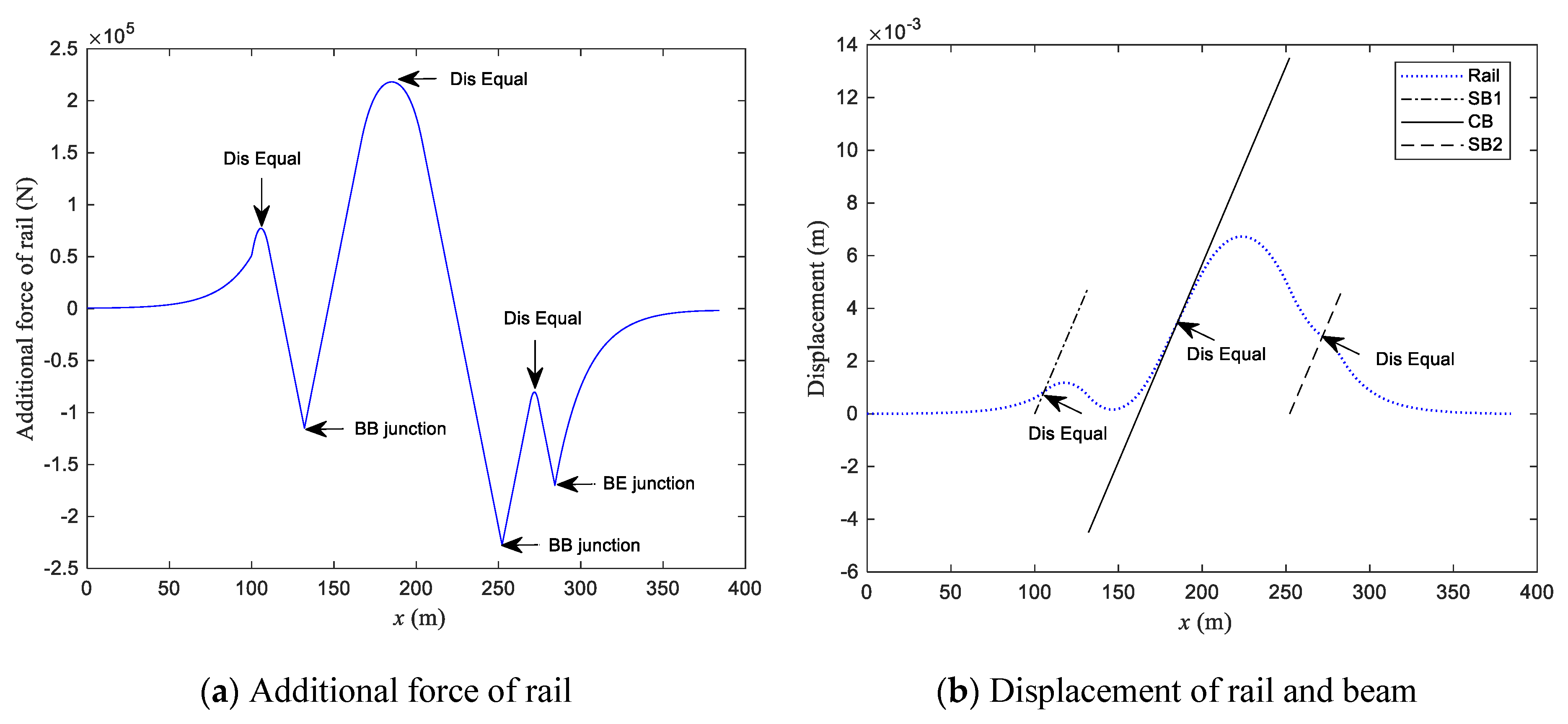
In order to more clearly show where the extreme value of the additional force occurs, a continuous beam with the length of 120 m and only two simple beams are considered. Figure 9 plots the additional force of rail along its length and the displacements of rail and simple and continuous beams, in which the abscissa indicates the distance between a certain section and the left end of the rail. Three extreme values of additional forces appear at the points of u R = u B , which have been marked with “Dis Equal” in Figure 9a, and these three points are clearly shown in Figure 9b. The other three extreme values of additional forces appear at three junctions: two junctions of beams and one junction between the beam and the embankment, which have been marked with “BB junction” and “BE junction” in Figure 9a.

5.2. Appropriate Matching Location of Fixed Bearing with RER

Since the appropriate location of RER has been studied, the fixed bearing of the continuous beam matching RER will be studied in the following sections. As the recommended location of RER is related to the length of the continuous beam, the shorter and longer continuous beams will be studied separately.

5.2.1. Shorter Continuous Beam

Since the critical length is 164 m, the lengths of 120, 135, and 150 m are studied as examples of the shorter length. RER above the middle of the continuous beam remains unchanged. Figure 10 shows the curves of the maximum additional tension and compression forces of rail with the change in location of the fixed bearing, in which the abscissa represents the distance of the fixed bearing and the left end of the continuous beam. It can be found from Figure 10 that the location of the fixed bearing has an obvious influence on the maximum additional forces of rail, and the maximum additional tension and compression forces of rail reach their minimum values when the abscissas are 44, 51.5, and 59 m, corresponding, respectively, to the lengths of 120, 135, and 150 m. At this moment, the fixed bearing is not located at the midpoint o c of the continuous beam, but at the midpoint o 0 of the distance L 0 . The reason is below. The distances L 0 are 152, 167, and 182 m for the lengths L c of 120, 135, and 150 m and the length L s of 32 m, respectively. The values of L 0 / 2 minus that of L s are 44, 51.5, and 59 m, corresponding to the three lengths of the continuous beam, respectively. This explains why the fixed bearing is located at the midpoint o 0 . One can also find that the maximum additional tension and compression forces of rail, corresponding to the left and right fixed bearings, are distributed symmetrically with each other. This symmetrical point is the midpoint o 0 .
As shown in Figure 10, the fixed bearing is arranged at the midpoint o 0 , which can ensure that the maximum additional force of rail reaches the minimum value. The further away the fixed bearing is from the midpoint o 0 , the greater is the maximum additional forces of rail.
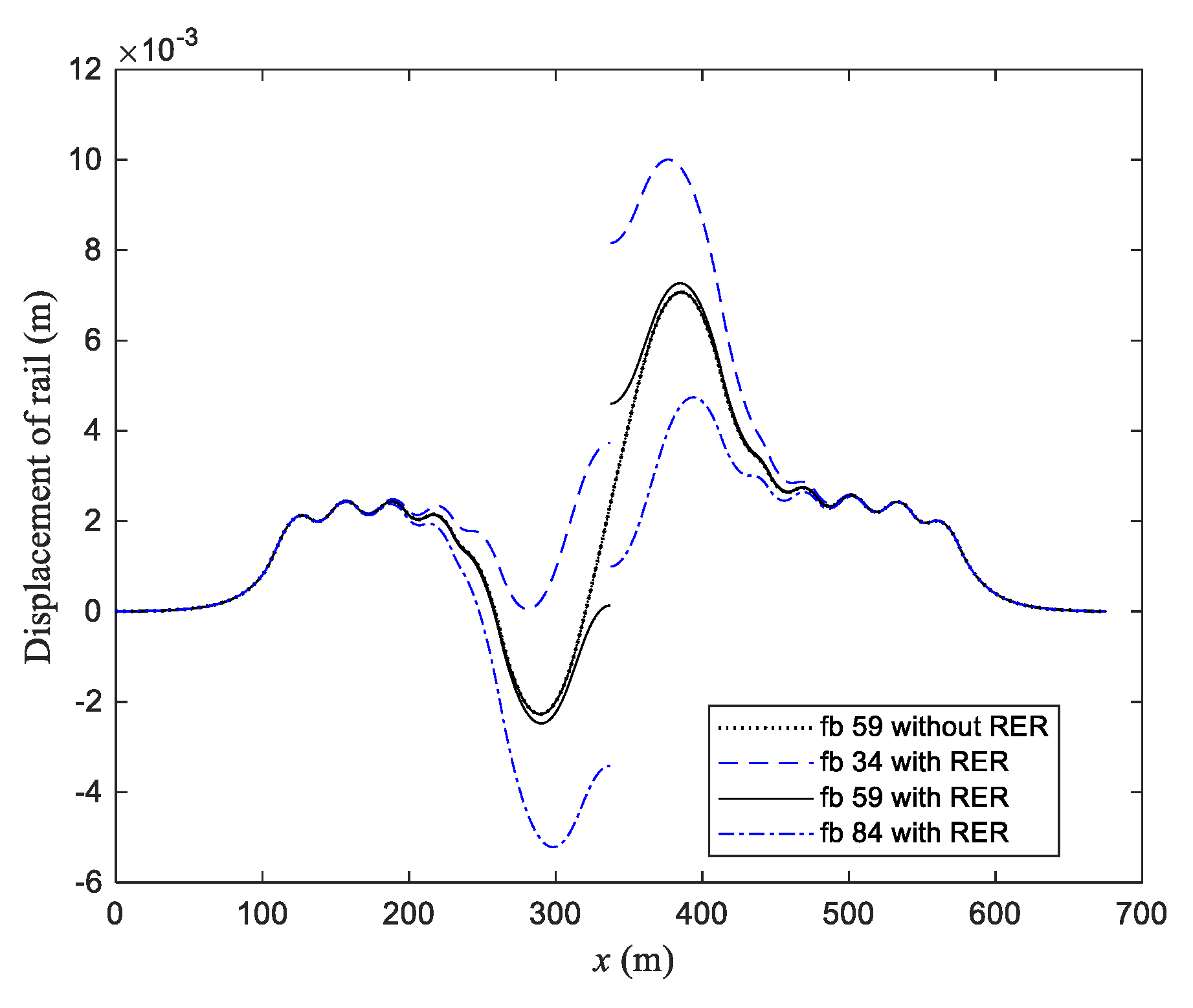
Three different locations are considered, with the l fb of 34, 59, and 84 m for the continuous beam of the length of 150 m and RER located above the middle of the continuous beam, as well as l fb of 59 m without RER. As shown in Figure 10, the l fb of 59 m corresponds to the maximum additional forces of rail reaching minimum values. The l fb of 34 m and 84 m are symmetrically distributed on two sides of the l fb of 59 m.
Figure 11 shows the four curves of additional forces of rail along its length for the four mentioned cases. In Figure 11, the additional force is zero when RER is set above the middle of the continuous beam, and RER can significantly reduce the additional tension force of rail near it. From the three curves with RER in Figure 11, one can observe that for the curve of “fb 59 with RER”, the additional compression forces of rail above the left and right ends of the continuous beam are almost equal, and they are maximum compression forces corresponding to the l fb of 59 m; in the meantime, the two extreme values of the additional tension force of rail, on the left and right sides of the RER on the continuous beam, is approximately equal, and they are also maximum tension forces corresponding to the l fb of 59 m.
The additional compression force of rail above the left end of the continuous beam in the curve of “fb 84 with RER” is almost equal to that above the right end of the continuous beam in the curve of “fb 34 with RER”, and they are maximum compression forces corresponding to the l fb of 84 and 34 m. At the same time, the extreme values of the additional tension force of rail on the left side of RER in the curve of “fb 34 with RER” is approximately equal to that on the right side of RER in the curve of “fb 84 with RER”, and they are maximum tension forces corresponding to the l fb of 34 and 84 m. This helps explain why the maximum additional forces in Figure 10 are symmetrical.
Figure 12 draws the curves of corresponding longitudinal displacement of rail. Similarly, the longitudinal displacement of rail is discontinuous at the location where RER is set. Since the RER is located above the middle of the continuous beam, the displacement of rail at the two ends of RER varies with the location of the fixed bearing.

5.2.2. Longer Continuous Beam

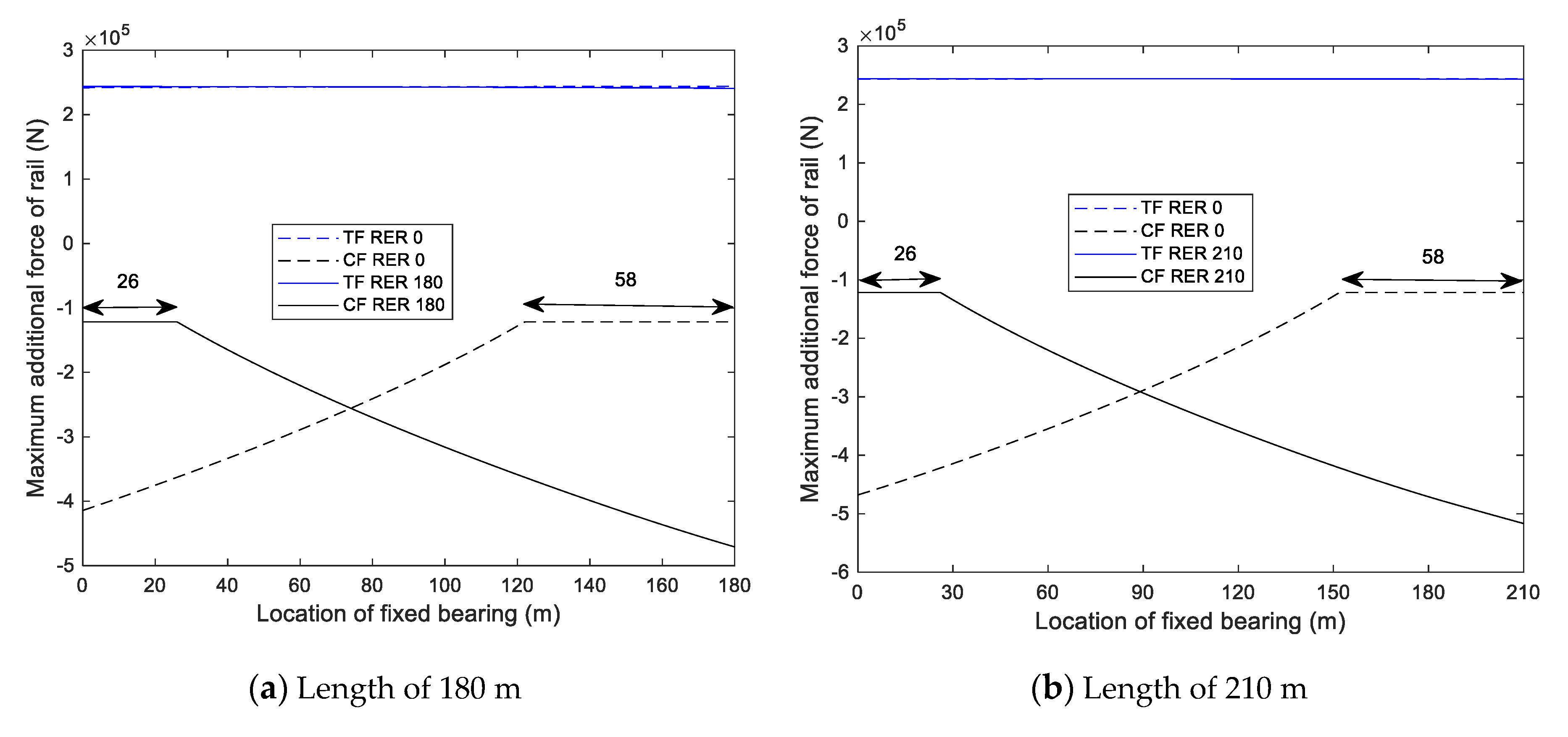
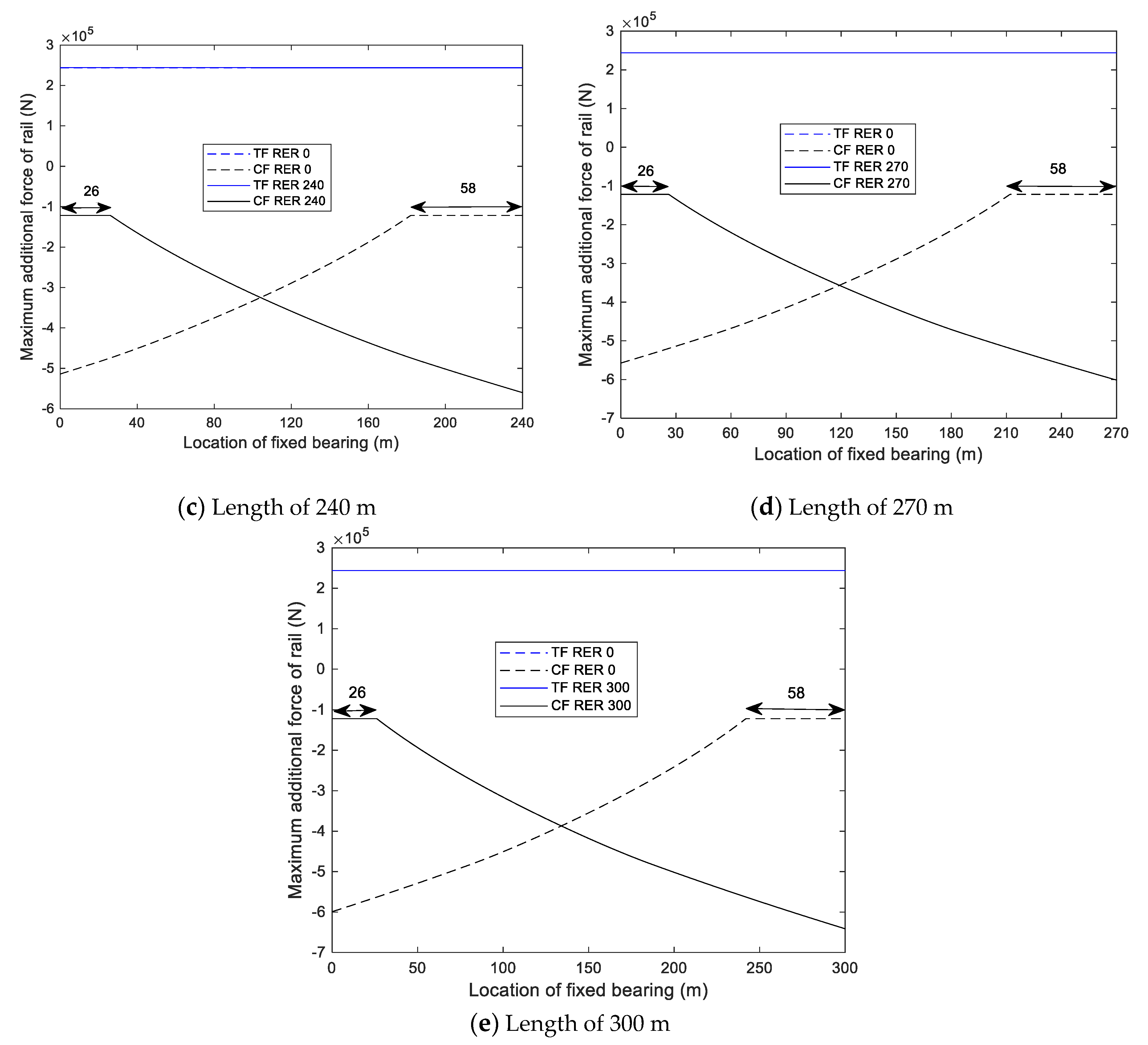
The continuous beams with the lengths of 180 to 300 m are studied with an interval of 30 m as examples of a longer length. The locations of RER are, respectively, above the left and right ends of the continuous beam, and they remain unchanged. The curves of the maximum additional compression and tension forces of rail with the change of the location of the fixed bearing can be obtained by using Step (8) in Section 4, and they are plotted in Figure 13, in which the abscissa represents the distance between the fixed bearing and the left end of the continuous beam. The figure shows that the change of the maximum additional tension force (TF) can be ignored, but that of the maximum additional compression force (CF) depends on the locations of RER and the fixed bearing. It can be seen from the figure that there is indeed an upper limit value for the maximum additional tension force of rail mentioned in Section 5.1. When RER is located above the left end of the continuous beam, regardless of the length of the beam, the change of CF can be ignored, for example, when the fixed bearing is located within 58 m of the right end of the beam; the number 58 is marked in Figure 13a–e. In the other locations, the change of CF is significant, and the closer the fixed bearing is to the left end of the beam, the greater the CF will be. When RER is located above the right end of the continuous beam, the change of CF can be ignored, with the fixed bearing located within 26 m near the left end of the beam. In fact, the distance between the fixed bearing of the continuous beam and the fixed bearing of the left simple beam neighbor to the continuous beam is also equal to 58 m, and it is the same as the range mentioned above. Similarly, the number 26 is marked in Figure 13a–e. At other locations, the change of CF is obvious, and the closer the fixed bearing is to the right end of the beam, the greater the CF will be.
Therefore, if RER is set above the left end of the continuous beam, the fixed bearing of the continuous beam should be arranged close to the right end of the continuous beam. Conversely, if RER is set above the right end, the fixed bearing should be arranged near the left end. This matching arrangement can reduce the maximum additional compression force of rail.
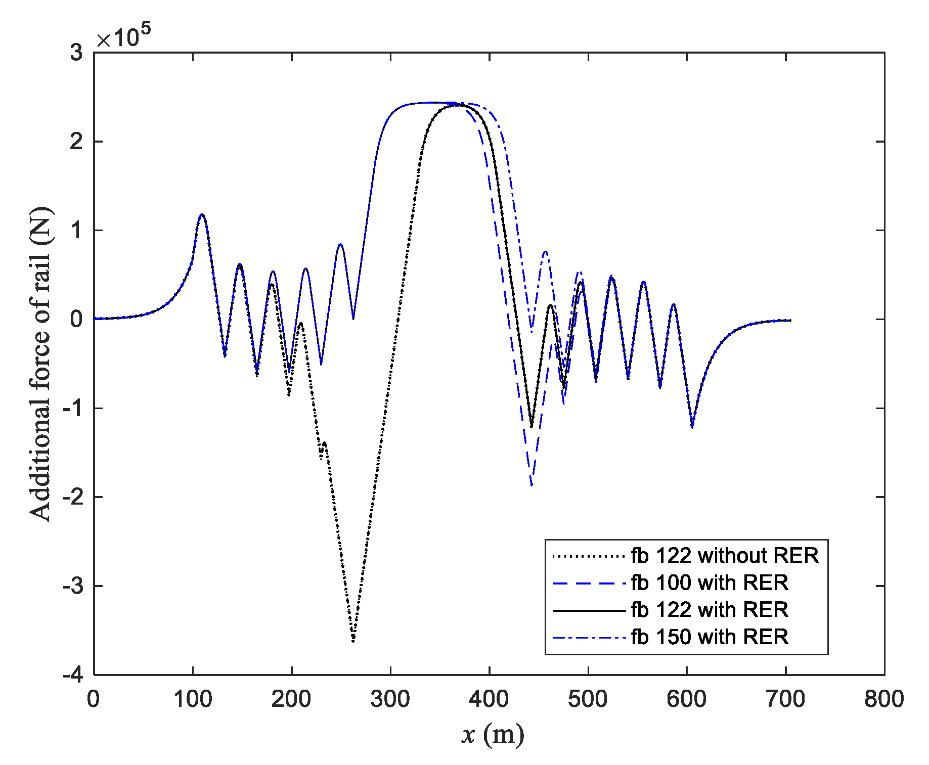
Here, three different locations are considered with the l fb of 100, 122, and 150 m for a continuous beam with the length of 180 m; RERs are located above the left end of the continuous beam. Figure 14 shows the corresponding additional force of rail along its length. The abscissa in Figure 14 represents the distance between a certain section and the left end of the rail. Three curves with RER are shown in Figure 14; the maximum additional tension forces of rail in the three curves are almost equal to each other, but the maximum additional compression forces are different. For l fb of 122 m, the additional compression force of rail above the right end of the continuous beam is equal to that above the right end of the last simple beam adjacent to the embankment, and they are the maximum compression force corresponding to l fb of 122 m. When l fb is smaller than 122 m, the force above the right end of the continuous beam is maximum, and it increases with the reduction of the distance. It is the significantly changed part of Figure 13a. When l fb is greater than 122 m, the force above the right end of the last simple beam adjacent to embankment is maximum, and it is not affected by the change of l fb . It is the unchanging part of Figure 13a.
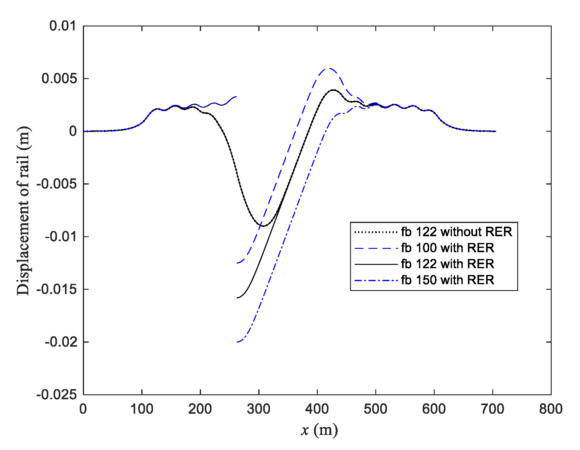
In order to compare the effect of RER, the curve with the legend of “fb 122 without RER” is also plotted in Figure 14. It can be found that the additional force is zero where RER is above the left end of the continuous beam, and RER can significantly reduce the additional force of rail near it. The curves of corresponding longitudinal displacement of rail are plotted in Figure 15. As shown in Figure 15, the longitudinal displacement of rail is discontinuous at the location where RER is set. The longitudinal displacement of the end of RER on the continuous beam increases with the value l fb , but that on the simple beam is unchanged, which is different from that in Figure 12.

6. Conclusions

This paper presents a nonlinear finite element model for a CWR track, with RER resting on the embankment and simple and continuous beams under the temperature change of the bridge, and then uses the method to determine the locations of RER and the fixed bearing of a continuous beam corresponding to the maximum additional forces of rail reaching minimum values and, furthermore, investigates the effect laws of any locations of RER and the fixed bearing on the maximum additional forces of rail. The obtained results can guide the design of the RER location and the fixed bearing location of a long-span continuous railway bridge to reduce the additional axial force in CWR induced by the bridge thermal effect. Several conclusions can be drawn.
(1)
When RER is arranged above the two ends of the continuous beam, the minimum value of the maximum additional compression force of rail does not change with the length of the continuous beam, but that of the tension force of rail increases with the length of the continuous beam, although the increase is small. However, when RER is arranged above the middle of the continuous beam, the minimum values of the maximum additional tension and compression forces of rail increase with the length of the continuous beam; in particular, the latter increases significantly.
(2)
As for the temperature rise of the beam, there is an upper limit value of the additional tension force of rail but no lower limit value of additional compression force, and when the temperature falls, the result just reverses. The limit value is P u = E A α B Δ T .
(3)
There is a critical length for the continuous beam. For the shorter length, RER should be arranged above the middle of the beam, while for the longer length, RER should be arranged above the two ends of the beam, which is conducive to reducing the additional forces of rail.
(4)
For RER arranged above the middle of the continuous beam, the fixed bearing is suggested to be located at the midpoint between the two fixed bearings of the simple beam neighbor to the continuous beam, which can reduce the maximum additional forces of rail. The further the fixed bearing is away from the midpoint, the greater is the maximum additional forces of rail.
(5)
When RER is arranged above one end of a continuous beam, the fixed bearing is arranged at the other end, as far as possible. This matching arrangement can ensure that the maximum additional compression force of rail reaches a minimum value.

Author Contributions

Conceptualization, P.L.; methodology, P.L.; investigation, P.L.; software, P.L.; supervision, P.L.; data curation, T.L.; validation, X.H. and G.H.; writing—original draft, P.L.; writing—review and editing, B.Y. All authors have contributed to the whole paper. All authors have read and agreed to the published version of the manuscript.

Funding

This research received no external funding.

Acknowledgments

This research was supported by the National Natural Science Foundation of China (Nos. 51578552, U1334203) and China Railway Corporation Science and Technology Research and Development Project (P2018G047).

Conflicts of Interest

We declare that we have no conflicts of interest in this work. We declare that we do not have any commercial or associative interest that represents a conflict of interest in connection with the work submitted.

References

  1. Frýba, L. Dynamics of Railway Bridges; Thomas Telford Ltd.: London, UK, 1996. [Google Scholar]
  2. Esveld, L.C. Modern Railway Track; MRT Production: Kâğıthane/İstanbul, Turkey, 2001. [Google Scholar]
  3. Cutillas, A.M. Track-Bridge Interaction Problems in Bridge Design; Taylor & Francis: Oxford, UK, 2009; pp. 19–28. [Google Scholar]
  4. Freystein, H. Track/bridge-interaction—State of the art and examples. Stahlbau 2010, 79, 220–231. [Google Scholar] [CrossRef]
  5. Chen, R.; Wang, P.; Wei, X.K. Track-bridge longitudinal interaction of continuous welded rails on arch bridge. Math. Probl. Eng. 2013, 494137. [Google Scholar] [CrossRef] [Green Version]
  6. Ruge, P.; Birk, C. Longitudinal forces in continuously welded rails on bridge decks due to nonlinear track-bridge interaction. Comput. Struct. 2007, 85, 458–475. [Google Scholar] [CrossRef]
  7. Ruge, P.; Widarda, D.R.; Schmälzlin, G.; Bagayoko, L. Longitudinal track-bridge interaction due to sudden change of coupling interface. Comput. Struct. 2009, 87, 47–58. [Google Scholar] [CrossRef]
  8. Ryjacek, P.; Vokac, M. Long-term monitoring of steel railway bridge interaction with continuous welded rail. J. Construct. Steel Res. 2014, 99, 176–186. [Google Scholar] [CrossRef]
  9. Zhang, J.; Wu, D.J.; Li, Q. Loading-history-based track-bridge interaction analysis with experimental fastener resistance. Eng. Struct. 2015, 83, 62–73. [Google Scholar] [CrossRef]
  10. Zhang, J.; Wu, D.J.; Li, Q.; Zhang, Y. Experimental and numerical investigation of track-bridge interaction for a long-span bridge. Struct. Eng. Mech. 2019, 70, 723–735. [Google Scholar]
  11. Alfred, S.; Saeed, K.; Martina, Š.; David, L.; Drahomír, N.; Frangopol, D.M.; Konrad, B. Monitoring based nonlinear system modeling of bridge-continuous welded rail interaction. Eng. Struct. 2018, 155, 25–35. [Google Scholar]
  12. Dai, G.; Chen, G.; Zheng, R.; Chen, Y.F. A new bilinear resistance algorithm to analyze the track-bridge interaction on long-span steel bridge under thermal action. J. Bridge Eng. 2020, 25, 04019138. [Google Scholar] [CrossRef]
  13. Yun, K.M.; Beomho, P.; Lim, N.H. Track-bridge longitudinal interaction response analysis considering the variation of temperature. J. Korean Soc. Hazard Mitig. 2015, 15, 65–71. [Google Scholar]
  14. Dai, G.L.; Liu, W.S. Applicability of small resistance fastener on long-span continuous bridges of high-speed railway. J. Cent. South Univ. 2013, 20, 1426–1433. [Google Scholar] [CrossRef]
  15. Liu, W.S.; Dai, G.L.; Yu, Z.W.; Chen, Y.F.; He, X.H. Interaction between continuous welded rail and long-span steel truss arch bridge of a high-speed railway under seismic action. Struct. Infrastruct. Eng. 2018, 14, 1051–1064. [Google Scholar] [CrossRef]
  16. Xie, K.; Zhao, W.; Cai, X.; Wang, P.; Zhao, J. Mechanical analysis and arrangement study of REJ for CWR on cable-stayed bridge. J. Railw. Eng. Soc. 2018, 35, 36–41. (In Chinese) [Google Scholar]
  17. Ramos, O.R.; Schanack, F.; Carreras, G.O.; Retuerto, J.D. Bridge length limits due to track-structure interaction in continuous girder prestressed concrete bridges. Eng. Struct. 2019, 196, 109310. [Google Scholar] [CrossRef]
  18. Yan, B.; Zhang, G.X.; Han, Z.S.; Lou, P. Longitudinal force of continuously welded rail on suspension bridge with length exceeding 1000 m. Struct. Eng. Int. 2019, 29, 390–395. [Google Scholar] [CrossRef]
  19. Lou, P.; Wang, Q.; Au, F.T.K.; Cheng, Y.W.; Yan, B.; Xu, Q.Y. Finite element analysis of the thermal interaction of continuously welded rails with simply supported bridges considering nonlinear stiffness. Proc. Inst. Mech. Eng. Part F J. Rail Rapid Transit 2020, 234, 1358–1367. [Google Scholar] [CrossRef]
  20. Liu, W.S.; Dai, G.L.; Qin, H.X. Influence of friction effect of sliding bearing on track-bridge interaction between continuous welded rail and long-span bridge in high-speed railway. Sci. Technol. 2019, 50, 627–633. (In Chinese) [Google Scholar]
  21. Yu, X.D.; Sha, S.; Yan, B. Track-bridge interaction of long-span simply supported steel truss bridge in mixed passenger and freight railway. Nat. Sci. 2014, 41, 106–111. (In Chinese) [Google Scholar]
  22. Wenner, M.; Marx, S.; Koca, M. Additional rail stresses due to long-term deformations of railway viaducts with ballastless track—Model and reality. Bautechnik 2019, 96, 674–695. [Google Scholar] [CrossRef]
  23. Mirza, O.; Kaewunruen, S.; Dinh, C.; Pervanic, E. Numerical investigation into thermal load responses of railway transom bridge. Eng. Fail. Anal. 2016, 60, 280–295. [Google Scholar] [CrossRef]
  24. Mirza, O.; Kaewunruen, S.; Galia, D. Seismic vulnerability analysis of Bankstown’s West Terrace railway bridge. Struct. Eng. Mech. 2016, 57, 569–585. [Google Scholar] [CrossRef]
  25. Choi, H.S.; Lee, K.C.; Lee, S.C.; Lee, J. Interaction analysis of sliding slab track on railway bridge considering behavior of end-supporting anchors. Int. J. Steel Struct. 2019, 19, 1939–1950. [Google Scholar] [CrossRef]
  26. Chinese National Standard, TB10015-2012. Code for Design of Railway Continuous Welded Rail; China Railway Publishing House: Beijing, China, 2012. (In Chinese) [Google Scholar]
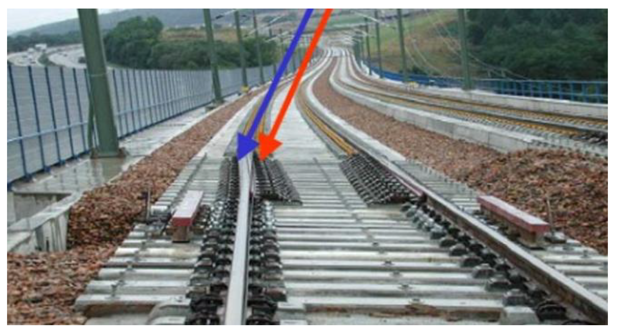
Figure 1. Photo of rail expansion regulator laid on site.
Applsci 10 06046 g001
Figure 2. Schematic planar model of a continuously welded rail (CWR) track with the rail expansion regulator (RER) resting on bridges and embankments.
Applsci 10 06046 g002
Figure 3. Longitudinal track–bridge coupling element.
Applsci 10 06046 g003
Figure 4. Linear and nonlinear relationships between q and u D .
Applsci 10 06046 g004
Figure 5. Distribution of the additional force and displacement on the rail.
Applsci 10 06046 g005
Figure 6. The curves of the minimum values of the maximum additional forces of rail changing with the location of RER for the length of 180 m of a continuous beam.
Applsci 10 06046 g006
Figure 7. The curves of the minimum values of the maximum additional forces of rail changing with the length of the continuous beam for RER located at three positions. In the legend, CF and TF represent the compression and tension forces, respectively, and Left, Mid and Right represent RER located the above the left end, the middle, and the right end of the continuous beam, respectively.
Applsci 10 06046 g007
Figure 8. Longitudinal forces acting in the mini segment of rail.
Applsci 10 06046 g008
Figure 9. Distribution of the additional force and displacements of rail and beam.
Applsci 10 06046 g009
Figure 10. The curves of the maximum additional forces of rail changing with the location of the fixed bearing of continuous beams with the lengths of 120, 135, and 150 m, in which RER is located above the middle of the beam.
Applsci 10 06046 g010
Figure 11. Additional force of rail along its length, with the fixed bearing located at three different positions for the length of 150 m of continuous beam.
Applsci 10 06046 g011
Figure 12. Longitudinal displacement of rail along its length, with the fixed bearing located at three different positions for the length of 150 m of continuous beam.
Applsci 10 06046 g012
Figure 13. The curves of the maximum additional forces of rail changing with the location of the fixed bearing of continuous beams with five different lengths, in which RER is located above the left and right ends of the beam.
Applsci 10 06046 g013aApplsci 10 06046 g013b
Figure 14. Additional force of rail along its length, with the fixed bearing located at three different positions for the length of 180 m of continuous beam.
Applsci 10 06046 g014
Figure 15. Longitudinal displacement of rail along its length, with the fixed bearing located at three different positions for the length of 180 m of continuous beam.
Applsci 10 06046 g015
Table 1. The CWR track parameters on continuous beam and embankment.
NotationItemValue
EModulus of elasticity of rail2.1 × 1011 N/m2
AArea of the cross-section of rail7.745 × 10−3 m2
α R Coefficient of thermal extension of rail1.18 × 10−5/°C
L c Length of continuous beam120 m
Δ T Temperature change of beam15 °C
α B Coefficient of thermal extension of beam1.0 × 10−5/°C
c spring stiffness per unit length and per rail of rail foundation on embankment and on beam, respectively4.4 × 106 and 1.6 × 10⁷ N/m2/rail
u ˜ B Critical value of relative displacement on beam0.5 mm
q ˜ B Constant longitudinal restoring force per rail corresponds to the critical value u ˜ B on beam8000 N/m/rail
u ˜ E Critical value of relative displacement on embankment2.0 mm
q ˜ E Constant longitudinal restoring force per rail corresponds to the critical value u ˜ E on embankment8800 N/m/rail
L E Length of CWR track on each side embankment100 m