Article

Development of Driftwood Capture Trellis for Capturing Driftwood in Agricultural Drainage Ditches

1
Department of Civil Engineering and Landscape Architectural, Daegu Technical University, Daegu 42734, Korea
2
Department of Aeronautics and Civil Engineering, Hanseo University, Seosan 31962, Korea
*
Author to whom correspondence should be addressed.
Appl. Sci. 2020, 10(17), 5805; https://doi.org/10.3390/app10175805
Submission received: 7 July 2020 / Revised: 16 August 2020 / Accepted: 18 August 2020 / Published: 21 August 2020
(This article belongs to the Special Issue The Advances in Fluid Mechanics)

Abstract

:
The flow of driftwood and soil into drainage from agricultural areas accelerates sedimentation and inflicts overflow damage after rainfall events due to insufficient discharge capacity, causing flooding on agricultural land. However, there have been few efforts to develop a driftwood capture trellis for agricultural drainage ditches, except for some suggested design criteria. In this study, we developed a driftwood capture trellis to capture driftwood in agricultural drainage ditches and evaluated its performance based on hydraulic characteristics. The facility was designed considering criteria for drainage and driftwood control barriers, as well as the properties of driftwood found near agricultural drainage ditches. Performance evaluation was conducted through hydraulic experiments. Driftwood capture trellises were installed in 400 mm drainage pipes and a total of 216 experimental runs were conducted: six runs each in six different velocity variations and six water depth variations. The results showed that the driftwood capture efficiency of the facility exceeded 60% at a velocity of 0.144 m³/s. Limited conditions for hydraulic experiments should be considered. The driftwood capture trellis for agricultural drainage ditches developed in this study could contribute to a reduction in overflow damage caused by driftwood sedimentation.

1. Introduction

Sedimentation of soil and debris into drainage pipes in urban and mountainous areas caused by local and sporadic rainfall may cause overflow damage if the discharge capacity of the drainage pipes is insufficient. The increased soil moisture resulting from drainage overflow increases the possibility of a disaster related to the flow of debris, thus increasing the risk of damage to life and property. A driftwood capture trellis or design standard for drainage facilities that protects against such damage should be considered; however, reduction measures related to drainage have not yet been established, domestically or internationally. Drainage systems are used in agricultural, urban, and mountainous areas that vary in size depending on intended use. Sudden local downpours of rain tend to occur more frequently in recent years due to climate change, and cause continuous damage despite various disaster prevention and reduction measures [1,2,3,4,5,6]. Design criteria for drainage systems have been established both domestically and internationally, but little research has been conducted on the development of driftwood capture trellises, as these facilities are mostly small-scale [7,8,9,10]. From 2009 to 2018 in the Republic of Korea, climate change increased rainfall, flooding 22,323 ha of farmland and inflicting damage on a 0.61 ha to 13,154 ha area. The main culprit of the farmland flooding was overflow caused by a lack of discharge capacity because of the sedimentation of driftwood and soil in the drainage system [11]. Therefore, formulation of measures to develop and maintain effective driftwood capture trellises and increase the discharge capacity of agricultural drainage ditch systems is an urgent concern.
Drainage research has mostly been centered around hydraulic experiments or numerical modeling. Empirical equations have been suggested to calculate the amount of discharge flowing through drainage systems, which take into account the longitudinal slopes of roadways, transverse slopes, local constants, and changes in interception capacity [12,13,14,15]. As for road drainage, hydraulic experiments were conducted to analyze the interception efficiency and the effects of sediment concentration and bed slope on driftwood flow deposition and runoff reduction [16,17,18,19,20]. Some researchers calculated nonuniform flow in drainage systems through numerical modeling or assessed the safety of installing driftwood capture trellises [21,22]. Previous research on drainage mostly focused on the calculation of inflow considering discharge, sedimentation, and flow characteristics, but the efficacy of drainage driftwood capture trellises and the effect of a lack of discharge capacity have not been adequately addressed.
Previous studies on driftwood capture trellises have been concentrated on hydraulic experiments or design methods for large-scale facilities related to landslide hazards, rather than on smaller drainage systems. The research has covered hydraulic characteristics, including design methods for bridges or culverts that aim to reduce driftwood, analysis of capture efficiency based on the size of driftwood, and regression equations for design improvements [23,24,25,26,27,28,29,30]. Some researchers have explored the characteristics of driftwood sedimentation locations and capture efficiency based on structural changes and screen spacing in permeable driftwood control barriers [31,32,33,34]. The capture efficiency of debris fins, screens, and deflector screens, among other debris control tools suggested by the Federal Highway Administration (FHWA [35]), have been analyzed; all except debris fins were found to be highly effective in reducing debris flow [36].
An examination of the drainage design criteria of different nations revealed that they only provide installation criteria, not standards for the operation of facilities to mitigate disasters. In large-scale drainage systems which have high-frequency designations, driftwood capture trellis debris control facilities or retention ponds can be established, but this is not common for most smaller drainage systems located in agricultural and mountainous areas. The U.S. Department of Transportation Federal Highway Administration (FHWA [35]) and the Ministry of Land, Infrastructure, and Transport of Korea recommend the installation of debris control facilities to keep debris out of storm drains connected to the drainage system [35,37]. Debris control structures are structures placed across well-defined channels to form basins which impede drainage flow. Practices that reduce the quantity of floating debris include directional felling uphill with a tree-pulling system and providing a buffer strip of undisturbed vegetation along the drains. Debris control structures are divided into six groups according to type of debris, as shown in Figure 1.
Debris can be grouped based on size into the following categories: light floating debris (LFD), medium floating debris (MFD), heavy floating debris (HFD), floating debris (FD1), fine detritus (FD2), coarse detritus (CD), and boulders (Table 1). Debris in the drainage from agricultural lands or plains is expected to include smaller twigs, dead leaves, grit, and sand; it is difficult to classify or define clear standards for the classification of such debris. According to the standards of the FHWA [35], LFD can be defined as debris found in drainage from plains and agricultural areas, while other types are found in mountainous areas and near streams [35]. The debris control structures suggested in the past were mostly for large-scale disaster mitigation facilities in mountainous areas and near streams. There is an urgent need for the development of debris driftwood capture trellises in small-scale drainage systems in plains and agricultural lands.
Many researchers have studied large-scale facilities, including permeable driftwood control barriers or facilities, in an attempt to alleviate the damage produced by sediment-related disasters. However, driftwood reduction methods in large-scale facilities, which mostly deal with logs, not twigs, in drainage systems, are of limited applicability to smaller facilities. In general, too little attention has been paid to driftwood capture trellises for agricultural drainage ditches, both domestically and internationally.
This study intends to develop a driftwood capture trellis that captures driftwood from agricultural drainage ditches. Using a hydraulic experiment, the study estimates driftwood capture efficiency under a variety of experimental conditions and establishes installation standards for agricultural drainage ditches. In addition, it aims to determine whether design discharge is installed and estimate the capture efficiency in various areas, by developing formulas that estimate discharge conditions and capture efficiency.

2. Materials and Methods

2.1. Drainage Design Criteria

Drainage refers to ditches created to drain water. Drainage is applicable to various facilities and is installed according to the recommended frequency (not based on size). Drainage systems are used as complementary facilities to culverts, roads, streets, and slopes. Different drainage design criteria exist depending on location and expected frequency, from a 2-year frequency to a maximum 100-year frequency (Table 2). The United States divides drainage systems into natural, major, and minor drainage methods, and plans around the occurrence of 2- to 100-year events [38,39]. Japan plans around 20- to 50-year events, based on its geographical characteristics and climate conditions [40]. In Canada, drainage design plans for a 2- to 100-year event depending on the geographical characteristics of the terrain in which drainage systems are installed [41]. In Australia, the frequency varies from 3 to 40 years depending on the purpose of the specific drainage system [42]. Korea classifies drainage systems into mountainous areas, plains, and agricultural lands and sets the frequency as 20 to 50 years for mountainous areas, 10 to 30 years for plains, and 20 years for agricultural lands. Additionally, it has been suggested that at least 20% of these systems should be adjusted based on estimated flood likelihood and in consideration of the sedimentation of driftwood and soil in drainage [7,8,9].
Drainage systems can be installed in a wide range of locations, including mountainous areas, plains, and farmlands. The recommended frequency is higher for drainage systems in agricultural and mountainous areas compared to plains and roads. This is because the probability of driftwood and soil inflow into the drainage is higher in agricultural and mountainous areas than in plains and roads. However, no adequate guidelines have been provided for installing and managing driftwood capture trellises to alleviate the damage from insufficient discharge capacity due to this increased driftwood flow. Against this backdrop, it is necessary to create guidelines for development and management of driftwood capture trellises in agricultural drainage ditch systems.

2.2. Definition of Driftwood in Agricultural Drainage Ditches

Regarding debris in agricultural drainage ditches, there are no clear standards for size or type except the suggestions of the FHWA [35], which classifies small twigs and wood chips as LFD [35]. This study presents a definition of driftwood in agricultural drainage ditches in order to help develop a driftwood capture trellis. The study looks at agricultural drainage ditches in the plains region in Chungcheongnam-do, Korea. Topographically, Chungcheongnam-do is the lowest area in Korea, with an average altitude of less than 100 m. It has an average annual temperature of 11–13 °C, and average annual rainfall of 1100–1350 mm. The basin area of agricultural drainage ditches where driftwood is collected is 3.67 ha. Agricultural drainage ditches located in the target region are square-shaped with a width of 400 mm and are installed in concrete. The circumference of the target region is about 1 km, and agricultural drainage ditches are installed around 600 m. For this study, twigs and wood chips were collected within 1 km of the agricultural area, in and around the location of agricultural drainage ditches (Figure 2).
In the agricultural drainage ditches area, driftwood from various plants and crops were collected that fell within a size range that would be able to flow into the agricultural drainage ditches. A total of 350 pieces of driftwood were collected that were 1 to 25 mm in diameter and 100 to 500 mm in length. More than 60% of the pieces of driftwood were within 2 to 6 mm in diameter. In addition, 90% of the collected driftwood specimens were 12 mm or less in diameter, and only about 10% were between 12 mm and 25 mm in diameter. The driftwood entering agricultural drainage ditches was confirmed to be mostly light floating driftwood (LFD). The details of the driftwood collected are shown in Table 3.

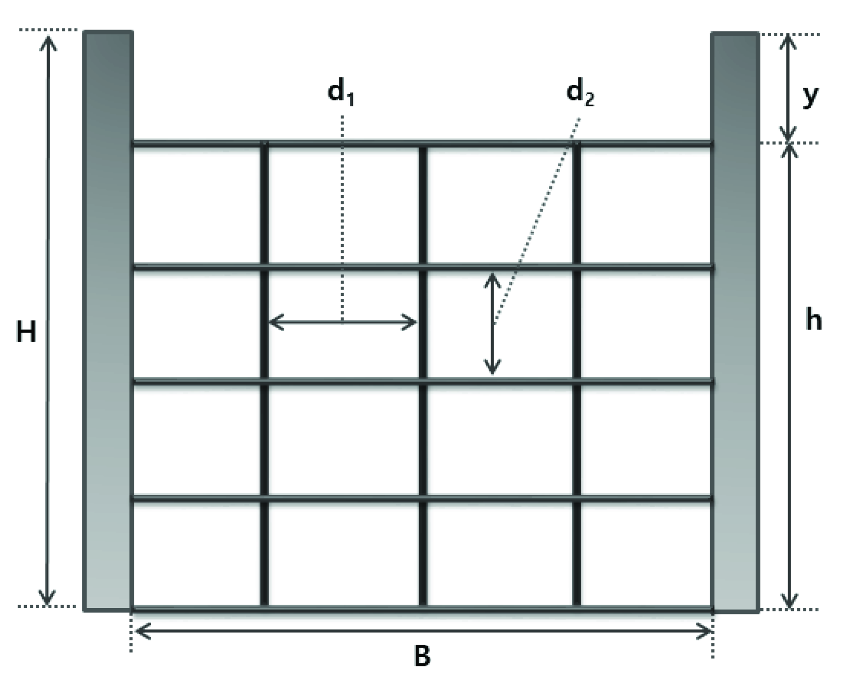
2.3. Development of Driftwood Capture Trellis for Agricultural Drainage Ditches

Few researchers have paid attention to the development of driftwood flow of driftwood capture trellises for agricultural drainage ditch systems. Most previous research has focused on large-scale damage mitigation facilities, including driftwood control structures or ring net barriers; smaller agricultural drainage ditch systems have not received sufficient attention. In this study, we examine drainage design criteria, driftwood control structures, and the characteristics of driftwood in order to develop a driftwood capture trellis for agricultural drainage ditches.
The study incorporated diverse standards for the driftwood flow of driftwood capture trellises, as follows. First, the installation of a driftwood capture trellis in agricultural drainage ditches was assumed to cause overflow damage due to the deposition of driftwood. To prevent overflow, we set the overflow height at 20% of the drainage height, as suggested in established design criteria. Second, the standard for the driftwood to be reduced in agricultural drainage ditches was established at 12 mm or less in diameter. Third, the opening, which accounts for 80% of the drainage height in an agricultural drainage ditch system (the remainder is overflow), was designed with grates similar to those in driftwood flow of driftwood capture trellises. The horizontal and vertical net distance standards followed those of the design criteria for permeable driftwood barriers in Japan as there are no relevant existing criteria for general driftwood control facilities [43]. Permeable driftwood barriers are installed to capture driftwood flow and driftwood in sediment disasters, and the design criteria for the opening of the facility is set at 1.0 times the maximum diameter for the horizontal and vertical net distance. However, driftwood control barriers, which are large structures designed to capture driftwood or rocks, can be blocked by driftwood when used in smaller facilities such as agricultural drainage ditch systems. Thus, smaller facilities set the design criteria at 1.0 to 2.0 times the maximum diameter for the horizontal and vertical net distance. Since the driftwood collected around the agricultural drainage ditches had a maximum diameter of 25 mm, the horizontal and vertical net distance of the opening was set from 25 to 50 mm.
As mentioned above, the driftwood capture trellis for agricultural drainage ditches suggested in this study was developed considering various design criteria. The parameters of the agricultural drainage ditch system are as follows: drainage width (B), drainage height (H), opening height (h), overflow height (y), horizontal net distance (d1), and vertical net distance (d2). A schematic design of the driftwood capture trellis is shown in Figure 3.

2.4. Manning Equation

The Manning equation is used to estimate the average velocity in open channels and pipe conduits. The roughness coefficient determined by the quality of riverbeds was applied by eliminating the depth effect of the Chezy coefficient. In addition, n is the roughness coefficient of the Manning equation, which is often determined by the quality and forms of riverbeds, but is rarely affected by flow characteristics. The Manning equation is shown in Equation (1).
V = 1 n R h 2 3 S O 1 2
where, V is average velocity, n is the roughness coefficient, Rh is hydraulic radius, and So is the slope of the hydraulic grade line. The depth estimated by the Manning equation is called the normal depth, and the riverbed slope at the normal depth is called the normal slope.

2.5. Froude Number

The Froude number refers to the inertial force ratio relative to the gravity of flow or the surface velocity ratio relative to the average velocity of flow. Flow states are divided into ordinary, critical, and supercritical flow, depending on the ratio of inertial force to gravity. The formula used to estimate the Froude number is shown in Equation (2).
F r = V g h
where, V is the local flow velocity, g is the gravitational acceleration, and h is the average depth of the channel section. If Fr < 1, the flow state is ordinary, and flow is dominated by gravity rather than by inertial force; such a flow, with relatively high depth and low velocity, seems to be normal. If Fr> 1, the flow state is supercritical, and is dominated by inertial force rather than by gravity; such a flow, with a relatively low depth and high velocity, seems to be non-normal.

3. Results

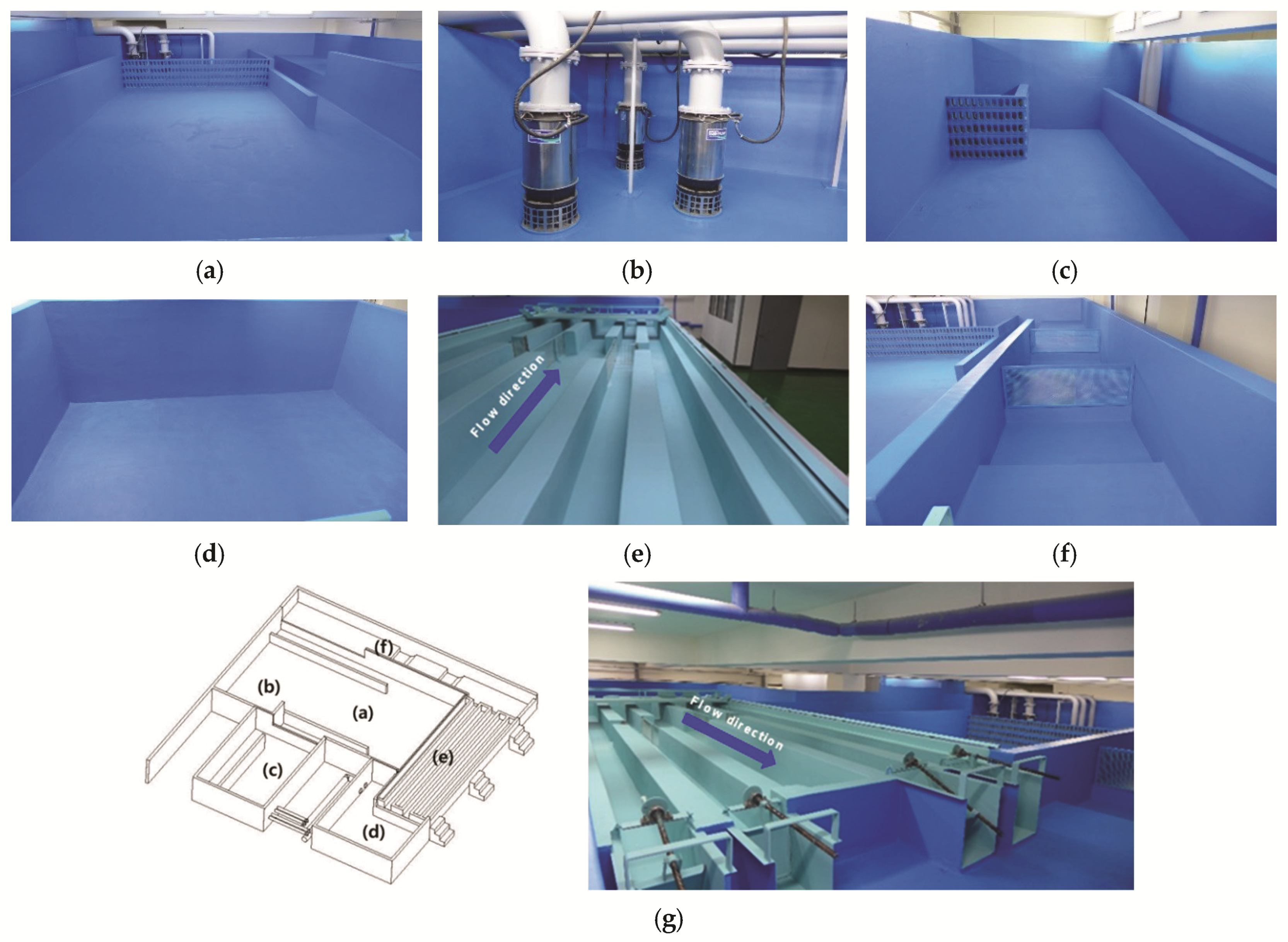
3.1. Characteristics of the Agricultural Drainage Ditches Hydraulic Lab

In prior studies, the specifications used for and the foundations of experiments in hydraulic laboratories were generally referenced, but details about the experimental set-up were limited. Furthermore, most hydraulic labs adopted scaled models to examine the hydraulic characteristics of large-scale facilities, which can confirm qualitative influences but are limited in their ability to show quantitative influences. In this study, a lab was built to conduct hydraulic experiments on an agricultural drainage ditch system at a scale of 1:1 to the actual drainage, as shown in Figure 4, so as to most clearly reveal the hydraulic characteristics of the drainage.
The hydraulic laboratory has a total area of approximately 306.25 m² (17.5 m wide and long). Water from the water tank is transferred to the head tank through the pump, and water is supplied to the drainage through the rectifying tank to ensure a stable supply of water. The available discharge was used at a rate of 0.32 m³/s with a width of 400 mm, a depth of 400 mm, and velocity of 2.0 m/s to model agricultural drainage ditches. The water used in the experiment was designed as a looping supply, since water is supplied to the water tank through the return tank. The entire system stores around 114 m³ of water (in the water tank, head tank, and rectifying tank). The maximum supply of water was maintained for five minutes in the hydraulic experiment. The width of the agricultural drainage ditches was 400 mm, which was the average size of the drainage troughs in the surveyed agricultural areas. The amount of stored water was sufficient to supply the water flow for the hydraulic experiment. The specifications of the hydraulic experiment for each facility in the laboratory are shown in Table 4.

3.2. Experimental Conditions

The conditions of the hydraulic experiment for agricultural drainage ditches were set for driftwood capture trellis, driftwood, and experimental conditions. Driftwood capture trellises for agricultural drainage ditches are areas that have not yet been studied at the domestic and international level. It is difficult to apply the same design criteria for large-scale driftwood capture trellises because design criteria for driftwood capture trellises for agricultural drainage ditches have not been established. Therefore, it is necessary to review additional experiments after preliminary application to existing unestablished research fields.
As mentioned above, the driftwood flow of the driftwood capture trellis designed in this study was developed considering various design criteria. A 400 mm wide agricultural drainage ditch was installed in the hydraulic laboratory along with a driftwood capture trellis with overflow height, opening height, and horizontal and vertical net distance as suggested in the design plan. The driftwood capture trellis was a square 400 mm in length, 80 mm in overflow height, 320 mm in opening height, 46 mm in horizontal net distance, and 35 mm in vertical net distance, with barriers 5 mm in diameter. The barriers were designed in an 8 × 8 grid, with horizontal and vertical net distances in the range of 1.0 to 2.0 times the maximum diameter of the driftwood, or between 25 and 50 mm. The driftwood capture trellis for agricultural drainage ditches developed in this study is shown in Figure 5.
It is difficult to apply driftwood collected in the vicinity of agricultural drainage ditches to various hydraulic experiments. In order to carry out many hydraulic experiments, it is necessary to apply the same sized driftwood in each. However, realistically, it is difficult to collect the same sized driftwood. Therefore, it is necessary to select an experimental tool that can provide the same size of driftwood and set it up according to the experimental conditions. Therefore, in this study, circular construction materials with various diameters were used. The opening of the agricultural drainage ditch pipe, excluding the overflow height, was 400 mm wide, 320 mm high, and had an area of 128,000 mm². In the experiment, 50% of the total opening area, or 64,000 mm², was applied as the size of one load of driftwood to test various velocity and water depth conditions. The length of the driftwood was set at 160 mm, or 50% of the opening height, and the driftwood had the shape of a round bar, similar to the twigs that were collected. The diameter of the driftwood was set at 12 mm or less, which represented 90% of the collected twigs, and there were 10 to 12 pieces of driftwood in one load with diameters of 3, 5, 7, 10, and 12 mm. The specifications of the driftwood used in the hydraulic experiments are shown in Table 5.
In the hydraulic experiments, the range of the discharge that can be supplied by the pump station was determined by the depth and velocity of the flow. The maximum discharge of the pump of the hydraulic laboratory was 0.33 m³/s, assuming a pump efficiency of 80%, so the experimental conditions were set at 0.26 m³/s or less, depending on the depth and velocity of the flow. As a result, six variations of the velocity (0.3, 0.6, 0.9, 1.2, 1.5, and 1.8 m/s) and six variations of the depth (0.08, 0.12, 0.16, 0.20, 0.24, and 0.28 m) were used. The discharge range was set at 0.01 to 0.20 m³/s to meet the pump capacity based on the efficiency of the hydraulic laboratory. A total of 216 runs of the experiment were conducted in this study. The experimental conditions were as follows: one variation for agricultural drainage ditches, one variation for driftwood capture trellis, six variations for velocity, six variations for water depth, and six repetitions of driftwood drops, as shown in Table 6.
A digital point gauge (PH-355) was used to observe depth and a one-dimensional electronic hydrometer (FLO-MATE 2000) was used to observe velocity under the hydraulic experiment conditions (Figure 6). The depth was measured by observing the distance at which the needle at the lowest part of the point gauge reached the surface of the water. The total length of the observer was 600 mm and the valid measurement length was 400 mm, with an accuracy of ± 0.01 mm and a margin of error of ± 0.04 mm. Velocity was measured by observing the potential difference between two sections of fluid flow. The measurable velocity ranged from 0 to 2 m/s, and 1 directional characteristic of velocity was observed.

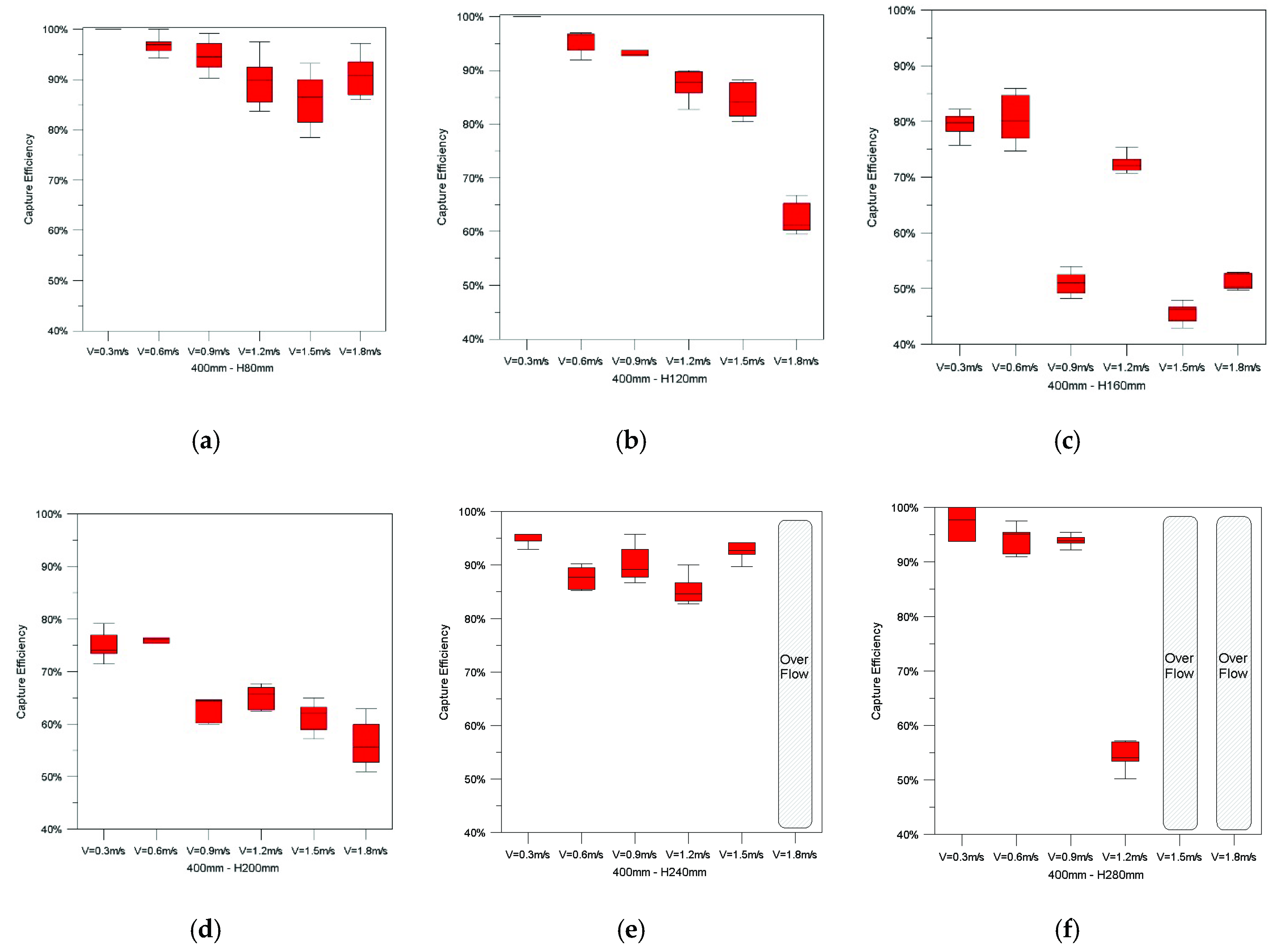
3.3. Driftwood Capture Efficiency of the Driftwood Capture Trellis

Out of the 216 runs of the experiment, six runs were conducted for each of six variations of velocity and six variations of water depth—36 different variations in total. During the experiment, overflow damage was observed in three runs: when the water depth was 240 mm and the velocity was 1.8 m/s, and when the water depth was 280 mm and the velocity was 1.5 m/s and 1.8 m/s. Overflow damage was attributable to insufficient discharge capacity. The results from the experiments on minimal and maximal velocity at which driftwood is captured according to depth condition are shown in Appendix A. The driftwood capture efficiency of the driftwood capture trellis was between 50 and 100%, as shown in Figure 7: 80–100% at 80 mm water depth; 60–100% at 120 mm water depth; 50–100% at 160 mm water depth; 50–95% at 200 mm water depth; 70–95% at 240 mm water depth; and 80–97% at 280 mm water depth.
The average capture efficiency observed during the six runs of the hydraulic experiment for each of the 33 conditions is shown in Table 7. The observed capture efficiency, which ranged from 50.88 to 100%, tended to decrease as the velocity increased at the same water depth. Capture efficiency increased with increasing velocity, and there was a difference of less than 20% to more than 50% depending on the water depth condition. This is most likely due to fluctuations in capture efficiency according to flow and location of the driftwood capture trellis grid. The flow effect changed to a supercritical flow at velocities greater than 1.2 m/s, and the capture efficiency rapidly decreased. In order to consider the flow effect on both depth and velocity, the installation conditions of the driftwood capture trellis are presented in terms of discharge and Froude number.

3.4. Hydraulic Performance Evaluation of the Driftwood Capture Trellis

Design standards for hydraulic structures are created depending on the design discharge and the characteristics of the region in Korea. In addition, the size of an agricultural drainage ditch is set so that a stable flow occurs at the design discharge. In order to consider various discharge and flow conditions, an equation for calculating discharge and Froude number was proposed. Given the capture efficiency obtained for the velocity and depth of the flow, discharge capture efficiency curves and Froude number were estimated using the continuity and Manning equations (Figure 8).
The size of agricultural drainage ditch systems is planned considering various discharge rates. Therefore, in order to install a driftwood capture trellis for agricultural drainage ditches, a regression equation was calculated using the estimated curve to consider the effect of capture efficiency according to flow rate and flow state. The regression equation used to estimate the capture efficiency of the driftwood capture trellis was CE = 101.6 243.8 × Q for flow and CE = 98.4 15.6 × F r for Fr. Here, CE is capture efficiency, Q is discharge, and Fr is Froude Number. According to the estimation curve, within the discharge range of 0.01 to 0.144 m³/s, the capture efficiency of the driftwood capture trellis was ≈ 60% or greater. The less the rate of discharge, the higher the capture efficiency: 80% capture efficiency was maintained at 0.10 m³/s or lower. As for the Froude number, the capture efficiency was estimated at ~80% or higher when Fr < 1, which represents a subcritical flow, and ≈ 60% or higher if 1 < Fr < 2.1, which represents a supercritical flow.
The driftwood capture trellis was found to capture approximately 60% of the driftwood in agricultural drainage ditches according to discharge rate and Froude number. However, when the flow rate in the drainage was 0.144 m³/s or greater, overflow occurred due to a reduction in the opening area caused by the captured driftwood. Based on these findings, the driftwood capture trellis in the agricultural drainage ditch system developed in this study would guarantee over 60% capture efficiency at a flow rate of 0.144 m³/s or less. Moreover, using such hydraulic characteristics as flow rate and Froude number, it is possible to establish installation standards for driftwood capture trellis according to the target capture efficiency. The capture efficiency of the regression equation proposed in this study is based on data obtained in various experiments. Although qualitative results were calculated using the regression equation, as discharge and increase, the volatility of the capture efficiency greatly increases. It is necessary to install driftwood capture trellises in consideration of this uncertainty.

4. Discussion

Most existing driftwood capture trellises for capturing driftwood are large-scale, such as erosion control facilities in mountainous areas or deflectors that prevent driftwood from entering sewer systems; small facilities such as those designed for agricultural drainage ditches have not yet been developed. In Korea, damage has continuously occurred from 2009 to 2018 due to a lack of discharge capacity in agricultural drainage ditches [11]. In spite of this continuous damage, effective smaller driftwood capture trellises have not been developed, in part due to the insufficient effects of the small-scale facilities that do exist and, therefore, incessant maintenance issues.
Most previous studies studied the effects of driftwood capture trellises by using hydraulic experiments, according to size and form [12,13,16,17,18,19,20]. This study developed a driftwood capture trellis for agricultural drainage ditches and suggested the normal discharge rate as less than 0.144 m3/s. The results of the hydraulic experiment showed that overflow damage occurred along with the capture of driftwood if the discharge rate exceeded 0.144 m3/s after the installation of the driftwood capture trellis. A formula for estimating the driftwood capture efficiency according to discharge conditions was proposed for the hydraulic experiment, and a capture efficiency of 60–100% was estimated at a discharge rate of less than 0.144 m3/s. The estimated capture efficiency in this study is higher than those seen in other studies based on hydraulic experiments [31,32,33,34].
It should be acknowledged that the facilities developed in this study have certain limitations. For example, they target driftwood flow without considering the influence of soil sedimentation. However, when driftwood and soil are combined, it is difficult to conduct hydraulic experiments or numerical modeling for driftwood capture trellises. Further studies are required to investigate the applicability of this type of agricultural drainage ditch facility and to assess the measures that must be taken to manage and maintain such facilities. In addition, the safety of the impact force of the driftwood capture trellis due to the inflow of driftwood must be considered. It is necessary to monitor actual rainfall events by installing the developed driftwood capture trellis at a test site. This will allow for establishment of maintenance standards considering the capture effect and impact force of driftwood from rainfall events.
It should be possible to maintain the effectiveness of driftwood capture trellises in continuous use. In addition, since the current study was limited to driftwood reduction, the influence of soil deposits in agricultural drainage ditches should be analyzed with numerical modeling in order to incorporate it in the development of future driftwood capture trellises for agricultural drainage ditches.

5. Conclusions

In this study, we developed a driftwood capture trellis to prevent overflow damage caused by the sedimentation of driftwood flowing into agricultural drainage ditches and evaluated the performance of the system through hydraulic experiments. According to the hydraulic experiment, a capture efficiency of 50.88–100.00% for driftwood in ditches in laboratory conditions was observed. Under several experimental conditions (i.e., discharge greater than 0.144 m3/s), overflow damage was observed. The driftwood capture trellis developed in this study is thus expected to be installed at sites with rates of discharge less than 0.144 m3/s.
The discharge was calculated according to the experimental conditions of water depth and velocity, and a regression equation for estimating the discharge condition and capture efficiency was proposed. The regression equation used to calculate the capture efficiency of the driftwood capture trellis considering discharge is CE = 101.6 − 243.8 × Q. At a flow rate of 0.01 to 0.144 m³/s, the capture efficiency was higher than 60% on the estimation curve, and the lower the flow rate, the higher the capture efficiency. The capture efficiency regression equation of the driftwood capture trellis considering Fr is CE = 98.4 − 15.6 × Fr. The capture efficiency was estimated at about 80% or higher if Fr < 1, which represents a subcritical flow, and about 60% or higher if 1 < Fr < 2.1, which represents a supercritical flow.
Based on the results of this study, the driftwood capture trellis will be useful in mitigating overflow damage by capturing driftwood in agricultural drainage ditches before it is deposited or flows into the drainage. Of course, there were limitations in terms of the number of experimental conditions used to develop the driftwood capture trellis, application of driftwood, and topographical characteristics. In addition, proper maintenance is required after installation of the driftwood capture trellis. Future research would greatly benefit from testing varying grid sizes to suit various topographical conditions and design facilities to meet a specific target capture efficiency.

Author Contributions

Conceptualization, Y.S. and M.P.; methodology, Y.S. and M.P.; validation, Y.S.; formal analysis: Y.S.; resources, Y.S. and M.P.; data curation, Y.S. and M.P.; writing-original draft preparation, Y.S.; writing-review and editing, M.P.; visualization, Y.S.; supervision, Y.S. and M.P.; project administration, M.P. All authors have read and agreed to the published version of the manuscript.

Funding

This work was funded by the Korea Meteorological Administration Research and Development Program under Grant KMI (2018-03010).

Conflicts of Interest

The authors declare no conflict of interest.

Appendix A

Figure A1. Capture efficiency of the driftwood capture trellis by experimental condition: (a) B400mm-H80mm-V0.3; (b) B400mm-H80mm-V1.8; (c) B400mm-H120mm-V0.3; (d) B400mm-H120mm-V1.8; (e) B400mm-H160mm-V0.3; (f) B400mm-H160mm-V1.8; (g) B400mm-H200mm-V0.3; (h) B400mm-H200mm-V1.8; (i) B400mm-H240mm-V0.3; (j) B400mm-H240mm-V1.5; (k) B400mm-H280mm-V0.3; (l) B400mm-H260mm-V1.2.
Applsci 10 05805 g0a1aApplsci 10 05805 g0a1b

References

  1. Chen, S.Y.; Xue, Z.C.; Li, M.; Zhu, X.P. Variable sets method for urban flood vulnerability assessment. Sci. China Technol. Sci. 2013, 56, 3129–3136. [Google Scholar] [CrossRef]
  2. Zhu, Z.; Chen, Z.; Chen, X.; He, P. Approach for evaluating inundation risks in urban drainage systems. Sci. Total Environ. 2016, 553, 1–12. [Google Scholar] [CrossRef] [PubMed]
  3. Yin, J.; Yu, D.; Yin, Z.; Liu, M.; He, Q. Evaluating the impact and risk of pluvial flash flood on intra-urban road network: A case study in the city center of Shanghai, China. J. Hydrol. 2016, 537, 138–145. [Google Scholar] [CrossRef] [Green Version]
  4. Pachauri, R.K.; Allen, M.R.; Barros, V.R.; Broome, J.; Cramer, W.; Christ, R.; Church, J.A.; Clarke, L.; Dahe, Q.; Dasgupta, P.; et al. Climate Change 2014: Synthesis Report. Contribution of Working Groups I, II and III to the Fifth Assessment Report of the Intergovernmental Panel on Climate Change; Core Writing Team, Pachauri, R.K., Meyer, L.A., Eds.; IPCC: Geneva, Switzerland, 2014; p. 151. [Google Scholar]
  5. Du, J.K.; Qian, L.; Rui, H.Y.; Zuo, T.H.; Zheng, D.P.; Xu, Y.P.; Xu, C.Y. Assessing the effects of urbanization on annual runoff and flood events using an integrated hydrological modeling system for Qinhuai River basin. China. J. Hydrol. 2012, 464, 127–139. [Google Scholar] [CrossRef]
  6. Yin, J.; Yu, D.; Yin, Z.; Wang, J.; Xu, S. Modelling the anthropogenic impacts on fluvial flood risks in a coastal mega-city: A scenario-based case study in Shanghai, China. Landsc. Urban Plan. 2015, 136, 144–155. [Google Scholar] [CrossRef]
  7. Ministry of Land, Transport and Maritime Affairs. Urban Roadway Design Guideline, 1st ed.; Ministry of Land, Transport and Maritime Affairs: Goyangsi, Korea, 2012. [Google Scholar]
  8. Korea Expressway Corporation. Design Criteria for the Roads in Mountain Area, 1st ed.; Korea Expressway Corporation: Sejong-si, Korea, 2006. [Google Scholar]
  9. Ministry of Land, Infrastructure and Transport. Slope Drainage Design Guideline, 1st ed.; Ministry of Land, Infrastructure and Transport: Jinjusi, Korea, 2016. [Google Scholar]
  10. AASHTO. AASHTO Highway drainage guidelines. In Task Force on Hydrology and Hydraulics; American Association of State Highway and Transportation Officials: Washington, DC, USA, 1999. [Google Scholar]
  11. Park, M.S.; Jo, J.H.; Yun, D.K.; Han, K.H. A Study on the improvement of rural drainage system to cope with climate change. In Proceedings of the Korea Water Resources Association Conference, Daegu, Korea, 20 May 2011; Korea Water Resources Association: Daegu, Korea, 2011. [Google Scholar]
  12. Wong, T.S.W. Kinematic wave method for determination of road drainage inlet spacing. Adv. Water Resour. 1994, 17, 329–336. [Google Scholar] [CrossRef]
  13. Wong, T.S.W.; Moh, W.H. Effect of maximum flood width on road drainage inlet spacing. Water Sci. Technol. 1997, 36, 241–246. [Google Scholar] [CrossRef]
  14. Tu, M.-C.; Traver, R.G. Optimal Configuration of an Underdrain Delivery System for a Stormwater Infiltration Trench. J. Irrig. Drain. Eng. 2019, 145, 05019007. [Google Scholar] [CrossRef]
  15. Zhang, H.; Wang, X.; Wang, L. An Analytical Solution of Partially Penetrating Hydraulic Fractures in a Box-Shaped Reservoir. Math. Probl. Eng. 2015, 2015, 726910. [Google Scholar] [CrossRef]
  16. Burgi, P.H.; Gober, D.E. Bicycle-Safe Grate Inlets Study: Hydraulic and Safety Characteristics of Three Selected Grate Inlets on Continuous Grades, 1st ed.; Federal Highway Administration, U.S. Department of Transportation: Washington, DC, USA, 1977. [Google Scholar]
  17. Pugh, C.A. Bicycle-Safe Grate Inlets Study: Hydraulic Characteristics of Slotted Drain Inlets, 4th ed.; Federal Highway Administration, U.S. Department of Transportation: Washington, DC, USA, 1980. [Google Scholar]
  18. Brown, S.A.; Stein, S.M.; Warner, J.C. Urban Drainage Design Manual: Hydraulic Engineering Circular No. 22, 1st ed.; Federal Highway Administration, U.S. Department of Transportation: Washington, DC, USA, 1996. [Google Scholar]
  19. Young-Il, K.; Jung-Cheol, B. Experimental investigation of effects of sediment concentration and bed slope on debris flow deposition in culvert. J. Korean Soc. Civ. Eng. 2011, 31, 467–474. [Google Scholar]
  20. Shin, H.J.; Won, C.H.; Choi, Y.H.; Kim, T.Y.; Choi, J.D. Study of installation of sediment trap drain channel to reduce soil erosion from storm water runoff. J. Korean Soc. Agric. Eng. 2010, 52, 95–100. [Google Scholar]
  21. Liu, J.; Nakatani, K.; Mizuyama, T. Effect assessment of debris flow mitigation works based on numerical simulation by using Kanako 2D. Landslides 2013, 10, 161–173. [Google Scholar] [CrossRef]
  22. Hye-Jin, K.; Gyeong-su, J. Varied flow analysis for linear drainage channels, Korea Water Resources Association. J. Korea Water Res. Assoc. 2008, 41, 773–784. [Google Scholar]
  23. Johnson, P.A.; Hey, R.D.; Horst, M.W.; Hess, A.J. Aggradation at Bridges. J. Hydraul. Eng. 2001, 127, 154–157. [Google Scholar] [CrossRef]
  24. Schmocker, L.; Hager, W.H. Probability of Drift Blockage at Bridge Decks. J. Hydraul. Eng. 2011, 137, 470–479. [Google Scholar] [CrossRef]
  25. Schmocker, L.; Hager, W.H. Scale Modeling of Wooden Debris Accumulation at a Debris Rack. J. Hydraul. Eng. 2013, 139, 827–836. [Google Scholar] [CrossRef]
  26. Chin, D.A. Hydraulic analysis and design of pipe culverts: USGS versus FHWA. J. Hydraul. Eng. 2013, 139, 886–893. [Google Scholar] [CrossRef]
  27. Dasika, B. New approach to design of culverts. J. Irrig. Drain. Eng. 1995, 121, 261–264. [Google Scholar] [CrossRef]
  28. Hager, W.H. Generalized culvert design diagram. J. Irrig. Drain. Eng. 1998, 124, 271–274. [Google Scholar] [CrossRef]
  29. Meselhe, E.A.; Hebert, K. Laboratory Measurements of Flow through Culverts. J. Hydraul. Eng. 2007, 133, 973–976. [Google Scholar] [CrossRef]
  30. Guven, A.; Hassan, M.; Sabir, S. Experimental investigation on discharge coefficient for a combined broad crested weir-box culvert structure. J. Hydrol. 2013, 500, 97–103. [Google Scholar] [CrossRef]
  31. Shrestha, B.B.; Nakagawa, H.; Kawaike, K.; Baba, Y.; Zhang, H. Driftwood deposition from debris flows at slit-check dams and fans. Nat. Haz. Earth Sys. Sci. 2012, 61, 577–602. [Google Scholar] [CrossRef]
  32. Lim, Y.H.; Chun, K.W.; Kim, M.S.; Yeom, J.J.; Lee, I.H. Capture effect of slit dam for debris flow and woody debris with hydraulic model experiment -Focusing on A and D type. In Proceedings of the 2008 Annual Summer Conference of the Korean Society of Forest Science, Jeonju-si, Korea, 21 August 2008; Korean Society of Forest Science: Jeonju-si, Korea, 2008. [Google Scholar]
  33. Geun-woo, J.; Young-hyeop, L.; Su-Yeon, N.; Su-Jin, J.; Yu-Seok, J.; Sang-yup, Y. Sediment and woody debris trap effect of h-type slit dam with model experiment. In Proceedings of the 2010 Annual Summer Conference of the Korean Society of Forest Science, Seoul, Korea, 14 September 2010; Korean Society of Forest Science: Seoul, Korea, 2010. [Google Scholar]
  34. Jin-hak, K.; Geun-woo, J.; Jung-il, S.; Joo-woong, Y.; Se-myung, K.; Yong-rae, K. Effects of float-board screen for catching drift woods and debris flows in urban areas. In Proceedings of the 2013 Conference of the Korean institute of Forest Recreation, Seoul, Korea, 11 April 2013; Korean Institute of Forest Recreation: Seoul, Korea, 2013. [Google Scholar]
  35. Douglas County. Storm Drainage Design and Technical Criteria Manual, 1st ed.; Douglas County: Englewood, CO, USA, 2008. [Google Scholar]
  36. Kim, S.J.; Kang, J.G.; Kim, J.T. An experimental study on debris reduction system for culvert. J. Korea Acad. Indust. Coop. Soc. 2017, 18, 696–706. [Google Scholar]
  37. Bradley, J.B.; Richards, D.L.; Bahner, C.D. Debris Control Structures: Evaluation and Countermeasures, 3rd ed.; U.S. Department of Transportation: Washington, DC, USA, 2005. [Google Scholar]
  38. Ministy of Agriculture, Forestry and Flsheries. Land Improvement Project Plan Design Standard Plan, 1st ed.; Ministy of Agriculture, Forestry and Flsheries: Tokyo, Japan, 2019. [Google Scholar]
  39. Ministry of Land, Infrastructure and Transport. Road Design Manual of Mountain Area, 1st ed.; Ministry of Land, Infrastructure and Transport: Sejong-si, Korea, 2007. [Google Scholar]
  40. Town of Castle Rock. Storm Drainage Design and Technical Criteria Manual, 1st ed.; Town of Castle Rock: Castle Rock, CO, USA, 2019. [Google Scholar]
  41. Department of Water Govement of Western Australia. Stormwater Management Manual for Western Australia, 1st ed.; Department of Water Govement of Western Australia: Perth, Australia, 2007. [Google Scholar]
  42. National Institute for Land and Infrastructure Management. Manual of Technical Standard for Designing Sabo Facilities against Debris Flow and Driftwood, 1st ed.; National Institute for Land and Infrastructure Management: Sabo, Japan, 2016. [Google Scholar]
  43. City of Toronto Technical Services Metro Hall. Design Criteria for Sewers and Watermains, 1st ed.; City of Toronto Technical Services Metro Hall: Toronto, ON, Canada, 2009. [Google Scholar]
Figure 1. Debris control structures: (a) deflector; (b) rack; (c) riser; (d) crib; (e) fin; (f) dam [35].
Applsci 10 05805 g001
Figure 2. Driftwood found near agricultural drainage ditches.
Applsci 10 05805 g002
Figure 3. Design of the driftwood capture trellis for agricultural drainage ditches.
Applsci 10 05805 g003
Figure 4. Hydraulic lab used to study agricultural drainage ditches: (a) water tank; (b) pump station; (c) head tank; (d) rectifying tank; (e) agricultural drainage ditches (400 mm); (f) return tank; (g) plan view.
Applsci 10 05805 g004
Figure 5. Driftwood capture trellis for agricultural drainage ditches: (a) driftwood capture trellis (plan); (b) photograph of the implemented driftwood capture trellis.
Applsci 10 05805 g005
Figure 6. Observation station: (a) digital point gauge; (b) one-dimensional electronic hydrometer.
Applsci 10 05805 g006
Figure 7. Capture efficiency of the driftwood capture trellis according to depth: (a) H = 80 mm; (b) H = 120 mm; (c) H = 160 mm; (d) H = 200 mm; (e) H = 240 mm; (f) H = 280 mm.
Applsci 10 05805 g007
Figure 8. Capture efficiency of the driftwood capture trellis by hydraulic characteristics: (a) capture efficiency by discharge; (b) capture efficiency by Froude number.
Applsci 10 05805 g008
Table 1. Type of debris.
Debris ClassificationType
Light Floating Debris (LFD)small twigs, wood chips, cloth
Medium Floating Debris (MFD)twigs, big wood chips
Heavy Floating Debris (HFD)log, timber
Floating Debris (FD1)fluent substances, including clay, silt, sand, pebble, wood chips
Fine Detritus (FD2)homogeneous silt, sand, and gravel without suspended solids deposited where flow is slow
Coarse Detritus (CD)coarse gravel, rack fragments
Boulders (B)boulder, large rock fragment in the event of a flood
Table 2. Frequency for drainage by country.
NationTarget AreasFrequency
U.S.All2 to 100 years
CanadaAll2 to 100 years
AustraliaAll3 to 40 years
JapanAll20 to 50 years
KoreaMountain Area20 to 50 years
Plain10 to 30 years
Agricultural Land20 years
Table 3. Driftwood found near agricultural drainage ditches.
Diameter (mm)CountRation (%)Diameter (mm)CountRation (%)
1–2164.6 12–1361.7
2–34613.113–1451.4
3–46518.514–1561.7
4–5 5916.815–1620.6
5–6 4412.616–1710.3
6–7 349.717–1830.9
7–8164.618–1920.6
8–9164.619–2010.3
9–1092.620–2541.1
10–1172.0Sum350100.0
11–1282.3
Table 4. Specifications for hydraulic laboratory.
No.FacilitiesDimension
(Width × Depth × Height)
Capacity
(a)Water Tank11,000 mm × 6850 mm × 700 mm52.8 m³
(b)Pump Facilities15 HP × 2ea, 10 HP × 1ea0.33 m³/s
(c)Head Tank4000 mm × 6000 mm × 2000 mm48.0 m³
(d)Rectifying Tank5000 mm × 4000 mm × 700 mm14.0 m³
(e)Drainage4000 mm × 8750 mm × 400 mm1.4 m³
(f)Return Tank14,000 mm × 1500 mm × 200 mm4.2 m³
Table 5. Driftwood types and specifications.
DriftwoodLength (mm)Diameter (mm)CountEffective Cross-Sectional Area (mm²)
Applsci 10 05805 i0011603125760
5129600
71213,440
101016,000
121019,200
Sum4164,000
Table 6. Experimental conditions for agricultural drainage ditches.
Agricultural Drainage Ditches (Width(m))Driftwood Capture TrellisVelocity (m/s)Depth (m)No. of DropsNo. of Driftwood Drops
0.48 × 8 grid0.30.086 drops1 drop of driftwood = 41 pieces, ø3 mm ~ ø 12 mm in diameter
0.60.12
0.90.16
1.20.2
1.50.24
1.80.28
Number of experiment runs216
Table 7. Capture efficiency of the driftwood capture trellis by experimental conditions.
Water Depth (mm)Unit (%)
Velocity(m/s) 80120160200240280
0.3100.00100.0099.4494.6995.4497.31
0.696.8195.9490.4486.1387.6394.31
0.994.6993.1381.0086.5089.8193.94
1.289.5087.7582.1975.3184.8181.70
1.586.1384.3875.8871.6967.94overflow
1.880.5062.0050.8852.25overflowoverflow

