Investigation on Modeling and Formation Mechanism of Dynamic Rotational Error for Spindle-Rolling Bearing System

 ,
,
Abstract
1. Introduction
2. Modeling of Dynamic Rotational Error for Spindle-Rolling Bearing System
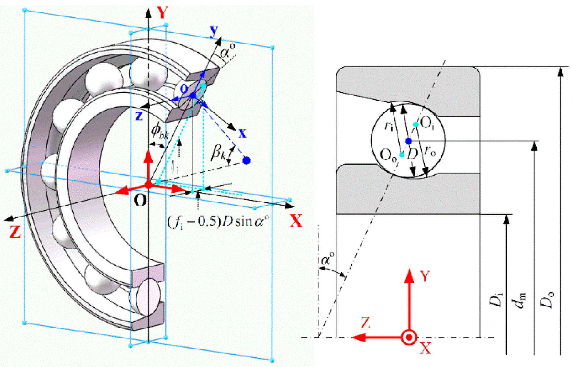
2.1. Nonlinear Bearing Model
2.1.1. Modeling of Dynamic Supporting Stiffness
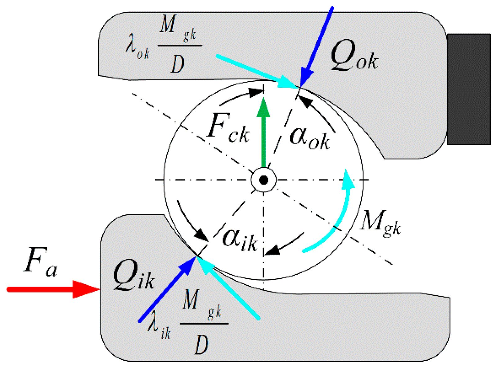
2.1.2. Modeling of Time-Varying Bearing Force
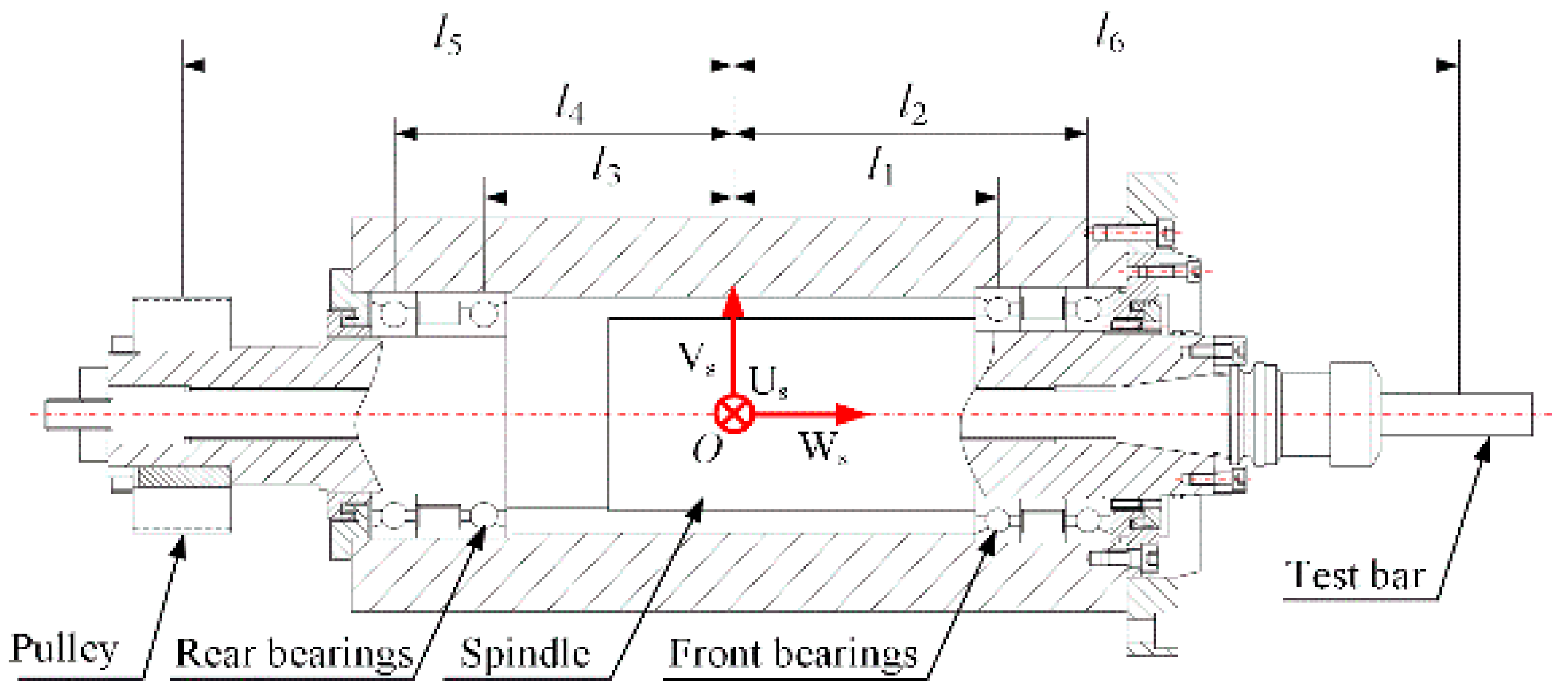
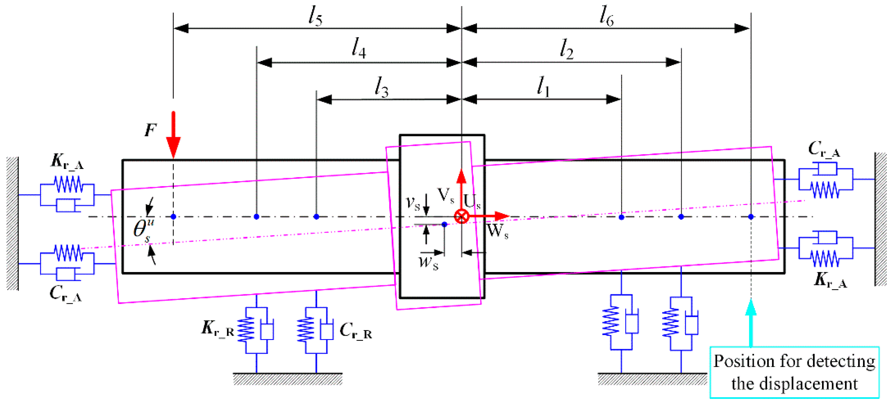
2.2. Dynamic Model of the SRB System
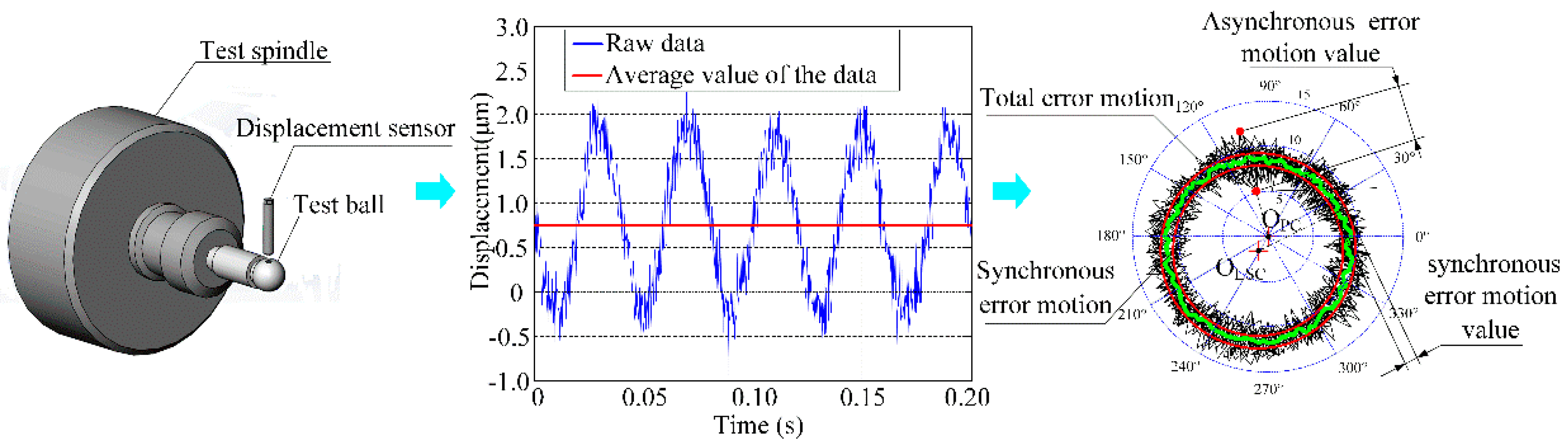
2.3. Evaluation of Dynamic Rotational Error
3. Numerical Simulation
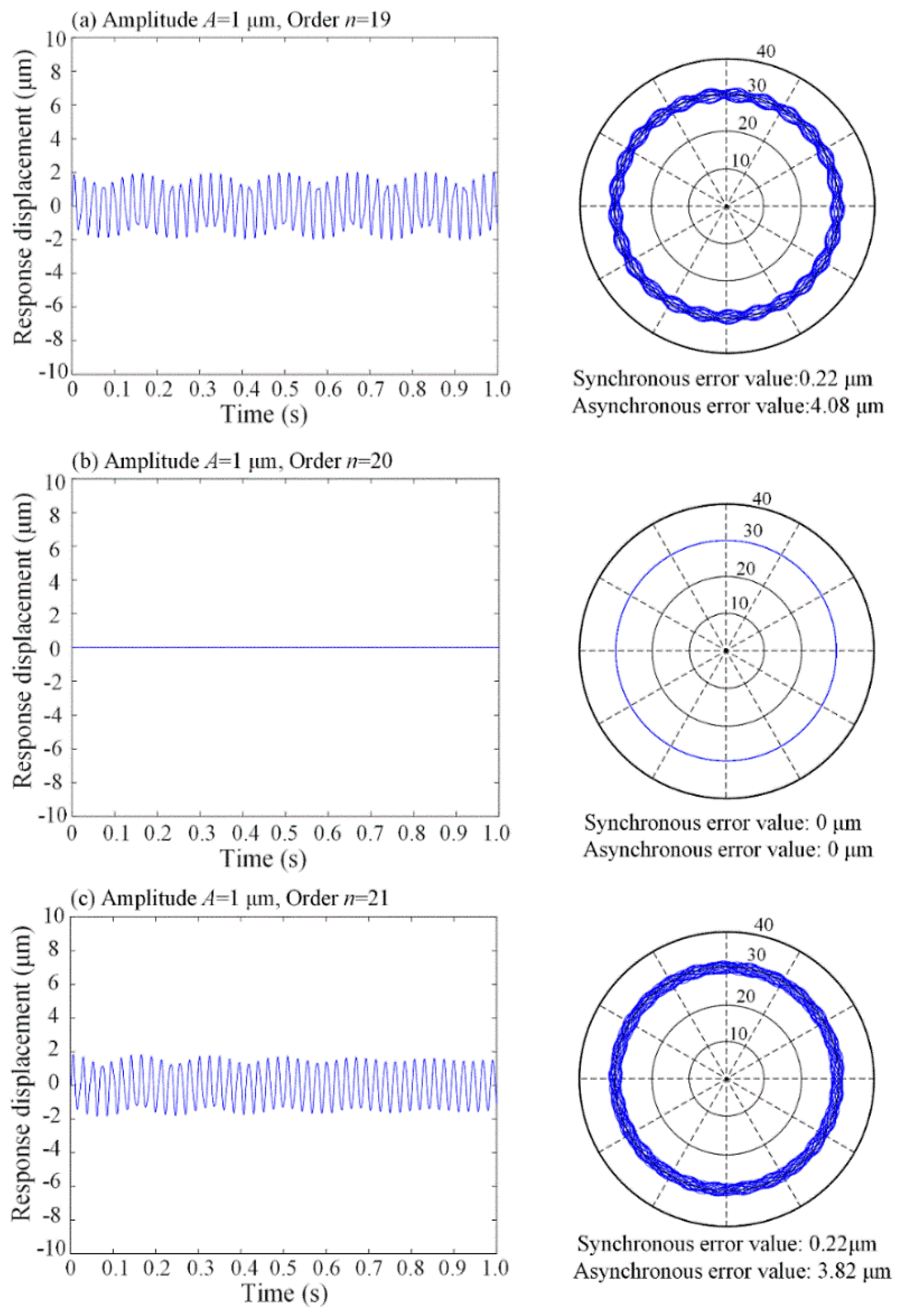
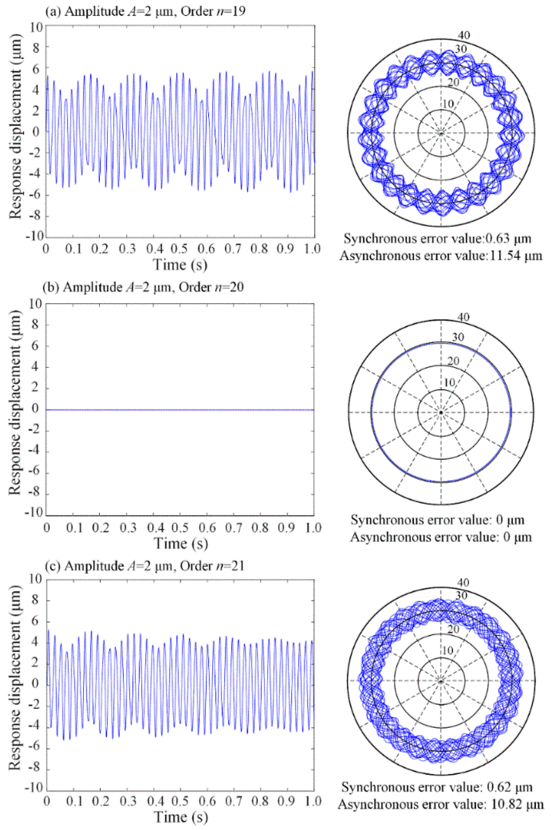
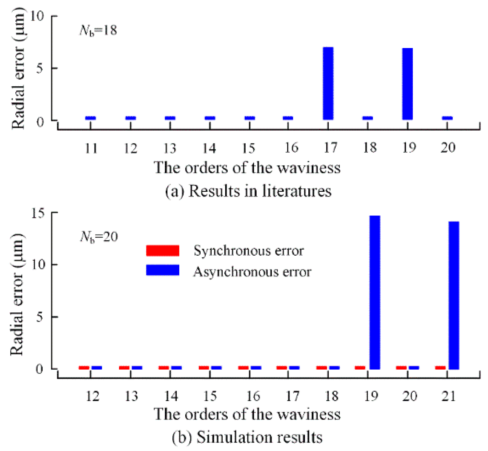
3.1. Influence of Bearing Raceway Waviness on Dynamic Rotational Error
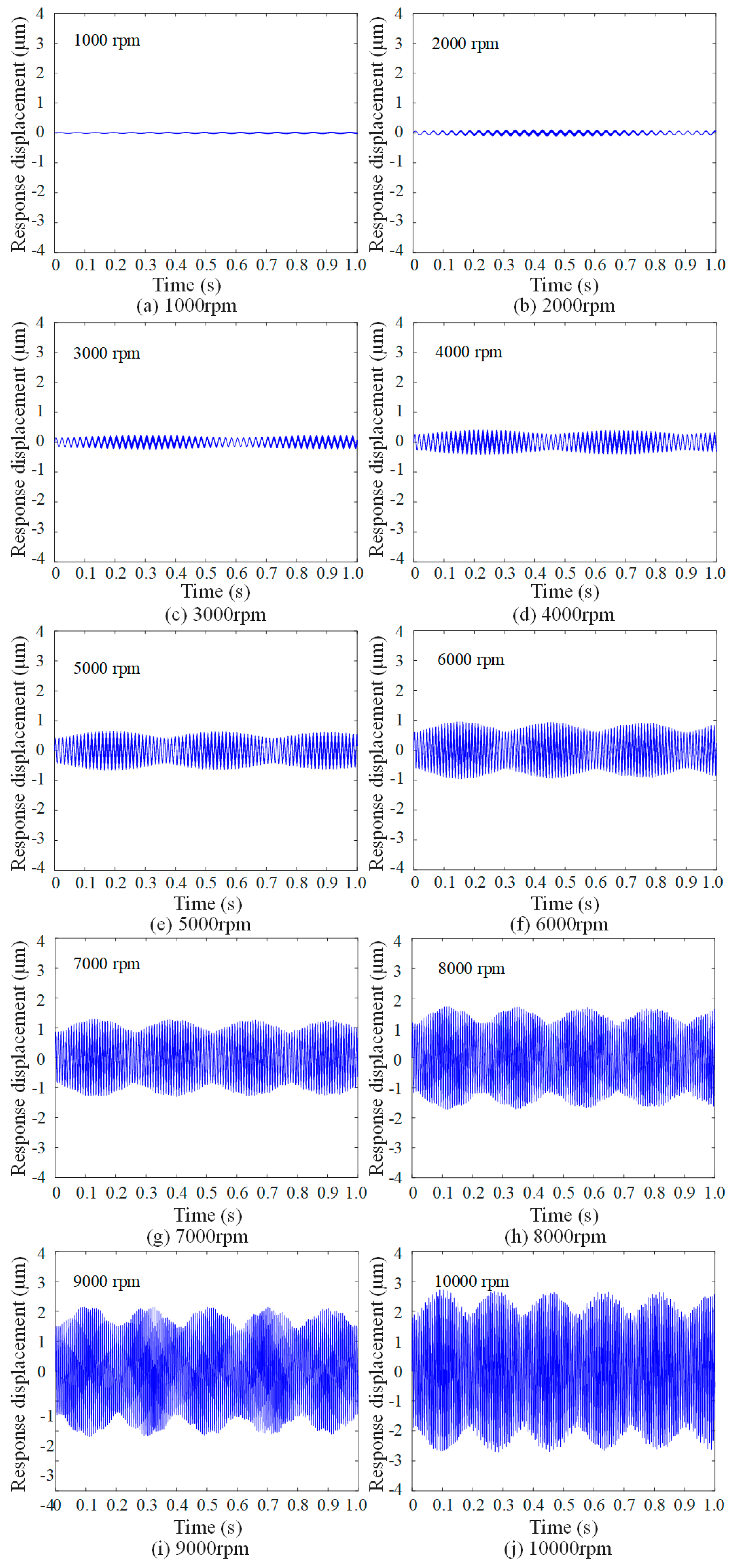
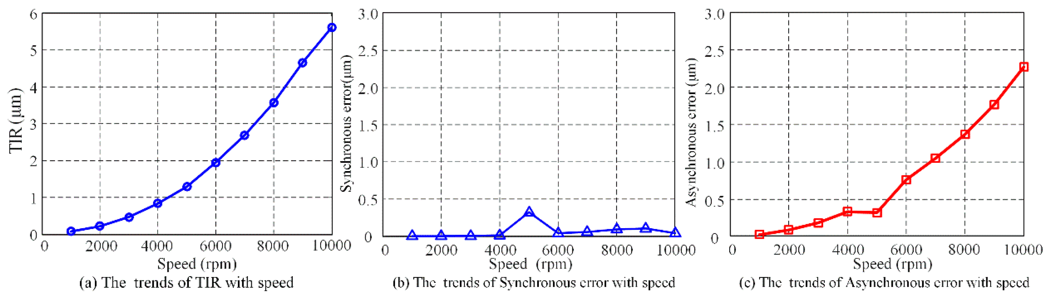
3.2. Influence of Dynamic Unbalance on Dynamic Rotational Error
3.3. Influence of Disturbance Force on Dynamic Rotational Error
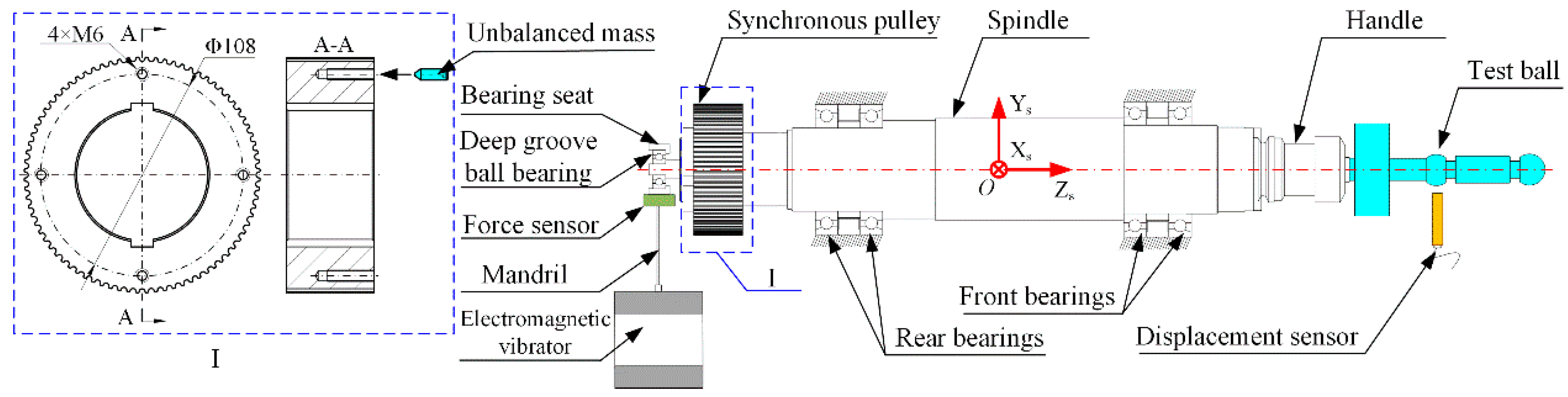
4. Experimental Validation
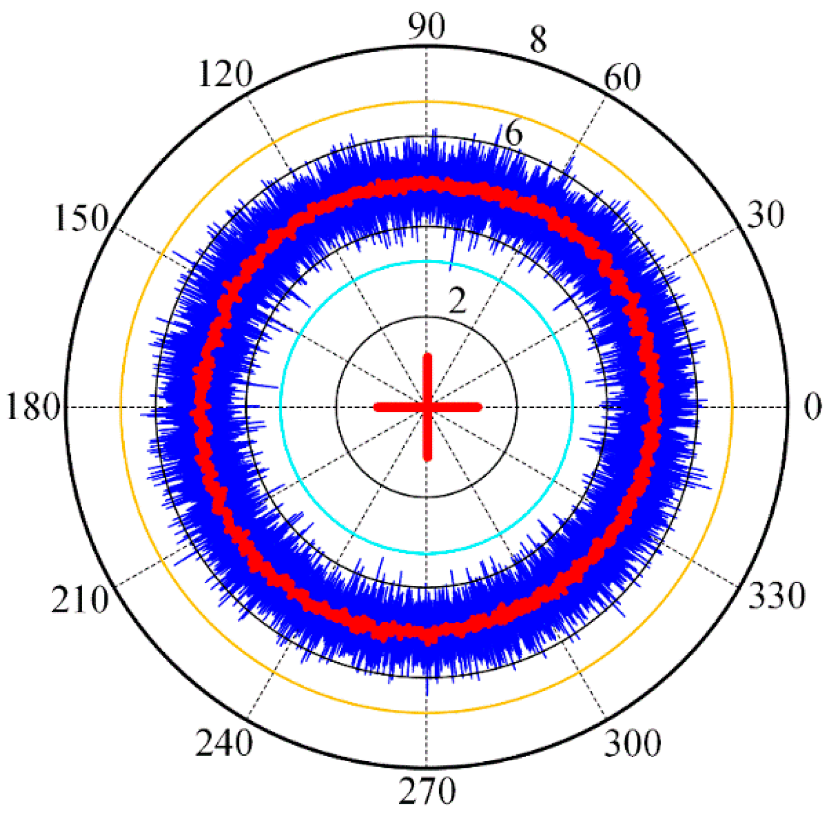
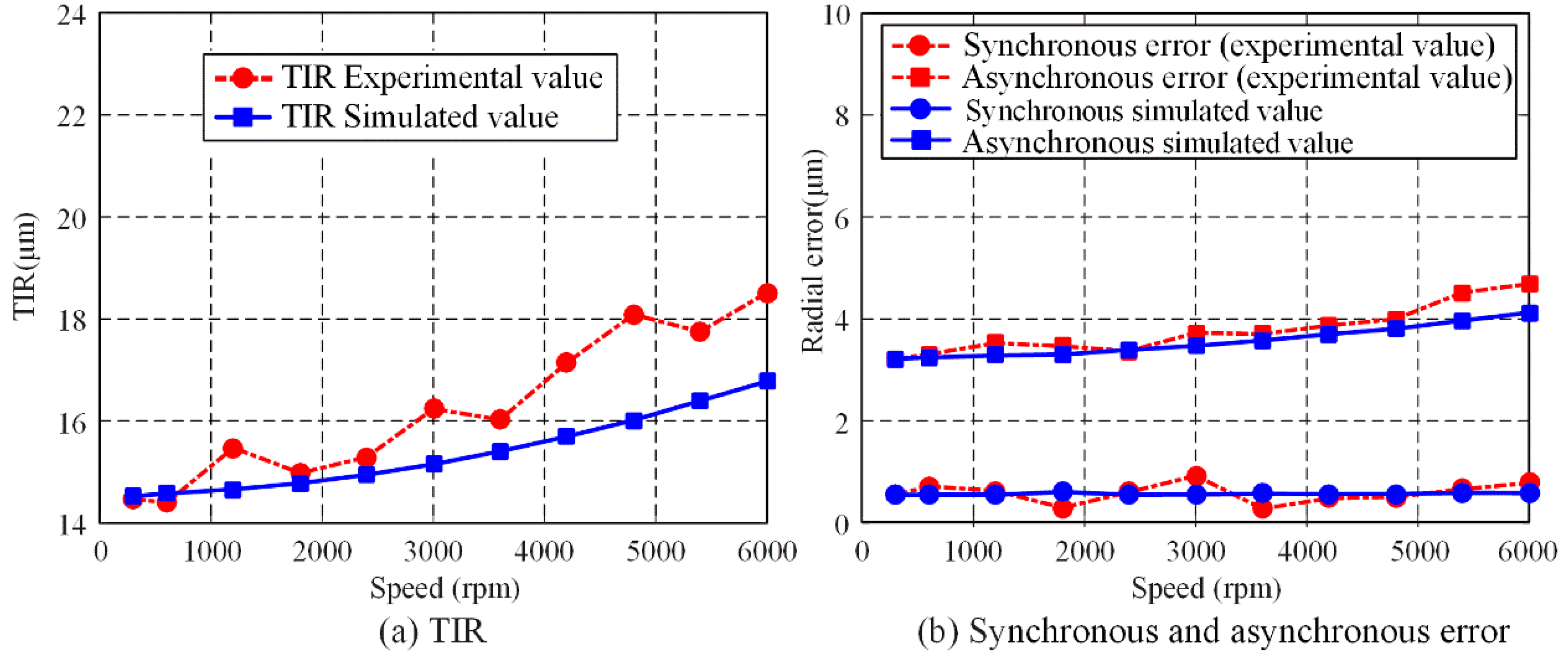
4.1. Validation of Dynamic Unbalance Force
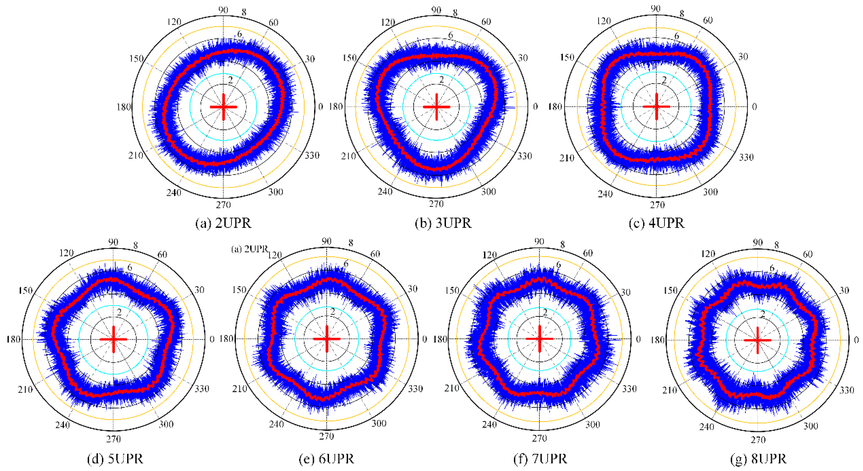
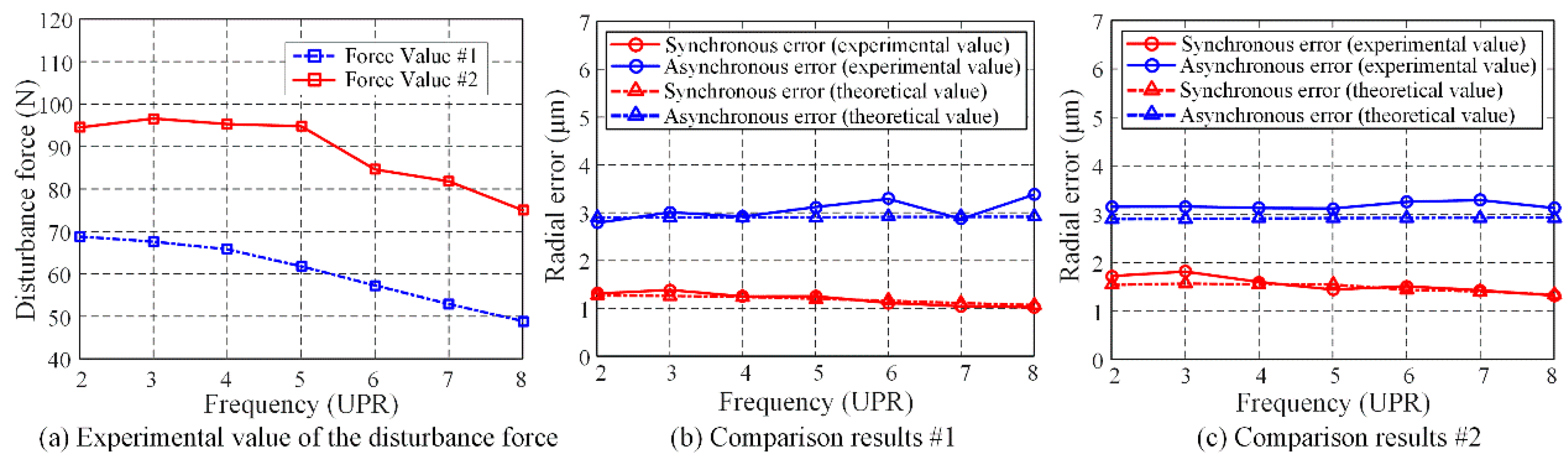
4.2. Validation of Disturbance Force
5. Conclusions
Author Contributions
Funding
Conflicts of Interest
Nomenclature
| δi | The displacement vector of the inner ring |
| ϕbk | The position angle of the kth ball |
| Nb | Number of the rolling element of the bearing |
| ω0 | The rotation angular speed of the inner ring (rad/s) |
| ωbk | The orbital angular speed of the rolling element (rad/s) |
| ωsk | The self-rotation angular speed of the rolling element (rad/s) |
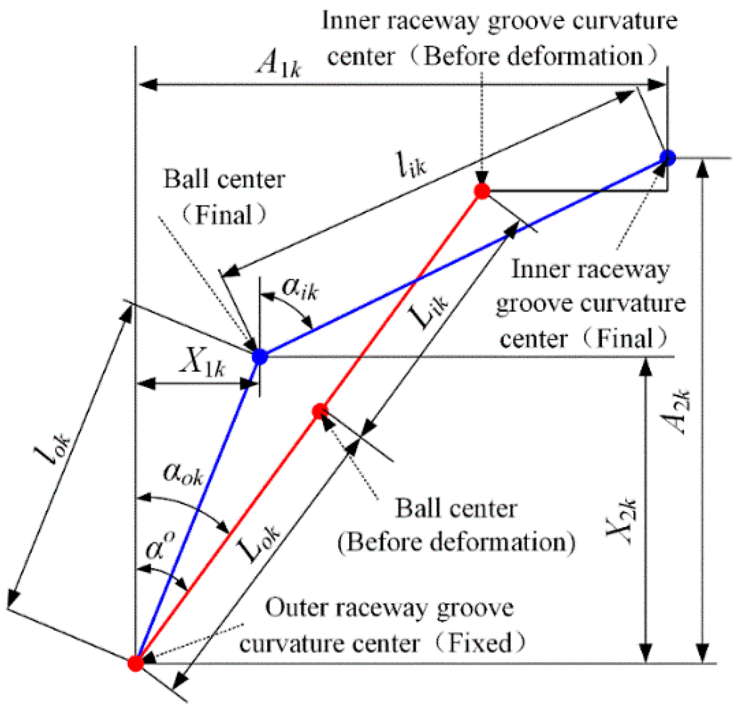
| αo | Initial contact angle of the bearing (°) |
| αik | Inner ring contact angle of the bearing of the kth rolling element (°) |
| αik | Outer ring contact angle of the bearing of the kth rolling element (°) |
| βk | The angle between the spinning axis of the rolling elements and Z axis (°) |
| D | The diameter of the rolling element (mm) |
| dm | Pitch Diameter (mm) |
| δik/δok | The contact deformation between the inner/outer bearing ring and kth rolling element |
| fi/fo | Inner/Outer groove curvature radius coefficient |
| ri/ro | Inner/Outer groove curvature radius (mm) |
| ηi | The distance between the rotating axis Z and inner raceway groove curvature center (mm) |
| Lik/Lok | The distance between the inner/outer raceway groove curvature center and the rolling element center before deformation |
| lik/lok | The distance between the inner/outer raceway groove curvature center and the rolling element center after deformation |
| Qik/Qok | The contact force between the inner/outer ring and the rolling element (N) |
| Mgk | Gyroscopic moment of the kth rolling element (N.mm) |
| Kok | Coefficient of the load-displacement between inner ring and kth rolling element (N/mm1.5) |
| Kik | Coefficient of the load-displacement between outer ring and kth rolling element (N/mm1.5) |
| λik, λok, | The friction coefficients between the inner/outer raceway and kth rolling element |
| Fck | The centrifugal force of kth rolling element (N) |
| Fi | The resultant force vector of the inner ring due to all of the contacting rolling elements (N) |
| Kb | The dynamic supporting stiffness matrix of the bearing (N/μm) |
| δik | The displacements for inner raceway groove curvature center corresponding to the kth rolling element (mm) |
| Tk | The transformation matrix |
| Δwk | The additional displacements caused by the waviness of the bearing rings and rolling elements (mm) |
| ΔDk | The additional displacements due to roundness error of the bearing rings and rolling elements (mm) |
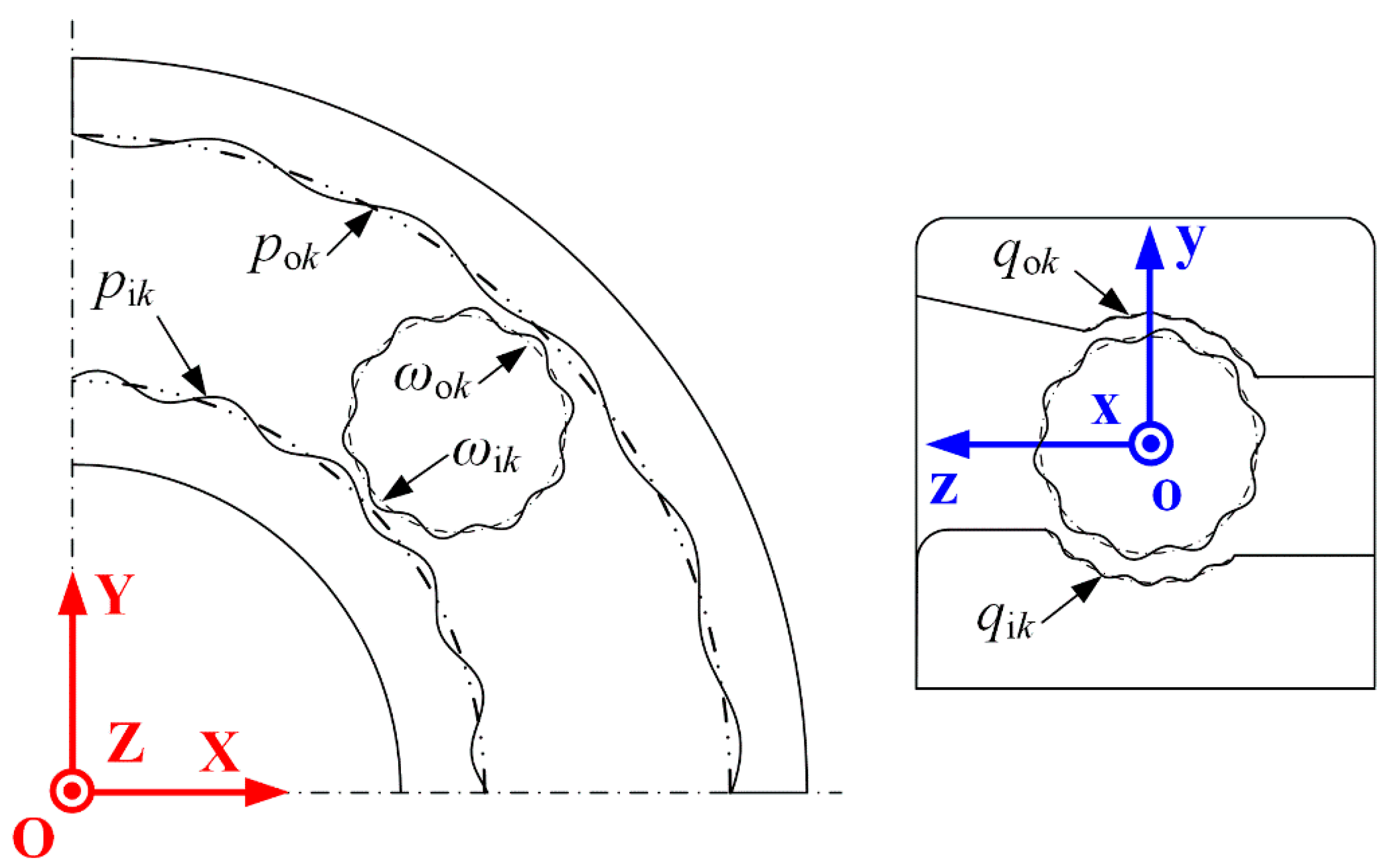
| pik, pok | The radial waviness of inner and outer raceways |
| pik, pok | The axial waviness of inner and outer raceways |
| wik, wok | The waviness of kth rolling elements |
| Ain, Aout, Bin, Bin, Cba, Cba | The amplitudes of the surface waviness |
| nin, nout, nba, | The harmonic orders of the surface waviness |
| ϕin, ψin, ϕout, ψout, φba | The initial phases angle of the surface waviness |
| Fb | The sum of the time-varying forces from all of the contacting rolling elements (N) |
| q | The dynamic displacement vector of the rotor |
| αi | Outer ring contact angle of the bearing (°) |
| C | The structural damping matrix of the system |
| G | The gyroscopic matrix of the system |
| Js | The inertia moment of the rotor about the Ws-axis |
| RLSC | The radius the least squares circle |
References
- Marsh, E. Precision Spindle Metrology, 2nd ed.; DEStech Publications: Lancaster, PA, USA, 2010; pp. 1–3. [Google Scholar]
- Kim, K.; Kim, S.S. Effect of preload on running accuracy of spindle. Int. J. Mach. Tools Manuf. 1989, 29, 99–105. [Google Scholar] [CrossRef]
- Scheslinger, G. Testing Machine Tools: For the Use of Machine Tool Makers, Users, Inspectors, and Plant Engineers, 3nd ed.; Pergamon Press: New York, NY, USA, 1978; pp. 3–9. [Google Scholar]
- Tlustry, J. System and methods for testing machine tools. Microtechnic 1959, 13, 161–162. [Google Scholar]
- Bryan, J.B.; Clouser, R.W.; Holland, E. Spindle accuracy. Am. Mach. 1967, 4, 149–164. [Google Scholar]
- ANSI/ASME. B89.3.4. Axes of Rotation: Methods for Specifying and Testing; ASME: New York, NY, USA, 2010; pp. 35–36. [Google Scholar]
- ISO 230-7. In Test Code for Machine Tools. Part 7: Geometric Accuracy of Axes of Rotation; International Standardization Organization: Geneva, Switzerland, 2006; pp. 16–19.
- Donaldson, R.R. A simple method for separating spindle error from test ball roundness error. CIRP Ann. Manuf. Technol. 1972, 21, 125–126. [Google Scholar]
- Zhang, G.X.; Wang, R.K. Four-point method of roundness and spindle error measurements. CIRP Ann. Manuf. Technol. 1993, 42, 593–596. [Google Scholar] [CrossRef]
- Evans, C.J.; Hocken, R.J.; Estler, W.T. Self-calibration: Reversal, redundancy, error separation, and absolute testing. CIRP Ann. Manuf. Technol. 1996, 45, 617–634. [Google Scholar] [CrossRef]
- Gao, W.; Kiyono, S.; Nomura, T. A new multiprobe method of roundness measurements. Precis. Eng. 1996, 19, 37–45. [Google Scholar] [CrossRef]
- Shi, S.Y.; Lin, J.; Wang, X.F.; Zhao, M. A hybrid three-probe method for measuring the roundness error and the spindle error. Precis. Eng. 2016, 45, 403–413. [Google Scholar] [CrossRef]
- Chen, Y.; Zhao, X.S.; Gao, W.G.; Hu, G.F. A novel multi-probe method for separating spindle radial error. Int. J. Adv. Manuf. Technol. 2017, 93, 623–634. [Google Scholar] [CrossRef]
- Jin, L.; Yan, Z.Y.; Xie, L.M. An experimental investigation of spindle rotary error on high-speed machining center. Int. J. Adv. Manuf. Technol. 2014, 70, 327–334. [Google Scholar] [CrossRef]
- Chen, D.J.; Fan, J.W.; Zhang, F.H. An identification method for spindle rotation error of a diamond turning machine based on the wavelet transform from artifact roundness error. Int. J. Adv. Manuf. Technol. 2012, 63, 457–464. [Google Scholar] [CrossRef]
- Lion Precision. Available online: http://www.lionprecision.com/sea/sea.html (accessed on 16 December 2019).
- Huang, Q.; Yu, Z.L.; Wei, K. General Modeling and Simulation Analysis Method on Rotating Accuracy of Spindle. Mach. Tool Hydraul. 2015, 43, 146–150. [Google Scholar]
- Huang, P.; Leen, W.B.; Chan, C.Y. Investigation of the effects of spindle unbalance induced error motion on machining accuracy in ultra-precision diamond turning. Int. J. Mach. Tools Manuf. 2015, 94, 48–56. [Google Scholar] [CrossRef]
- Kim, J.D.; Igor, Z.; Lee, K.B. Model of Rotation Accuracy of High-Speed Spindles on Ball Bearings. Engineering 2010, 2, 477–484. [Google Scholar] [CrossRef]
- Harsha, S.P.; Sandeep, K.; Prakash, R. Non-linear dynamic behaviors of rolling element bearings due to surface waviness. J. Sound Vib. 2004, 272, 557–580. [Google Scholar] [CrossRef]
- Harsha, S.P. Nonlinear dynamic response of a balanced rotor supported by rolling element bearings due to radial internal clearance effect. Mech. Mach. Theory 2006, 41, 688–706. [Google Scholar] [CrossRef]
- Jang, G.H.; Jeong, S.W. Nonlinear excitation model of ball bearing waviness in a rigid rotor supported by two or more ball bearings considering five degrees of freedom. J. Tribol. Trans. ASME 2002, 124, 82–90. [Google Scholar] [CrossRef]
- Bai, C.Q.; Xu, Q.Y. Dynamic model of ball bearings with internal clearance and waviness. J. Sound Vib. 2006, 294, 23–48. [Google Scholar]
- Wang, H.; Han, Q.K.; Zhou, D.N. Nonlinear dynamic modeling of rotor system supported by angular contact ball bearings. Mech. Syst. Signal Process. 2017, 85, 16–40. [Google Scholar] [CrossRef]
- Zhang, X.N.; Han, Q.K.; Peng, Z.K.; Chu, F.L. A new nonlinear dynamic model of the rotor-bearing system considering preload and varying contact angle of the bearing. Commun. Nonlinear Sci. 2015, 22, 821–841. [Google Scholar] [CrossRef]
- Li, X.H.; Yan, K.; Lv, Y.F.; Yan, B.; Dong, L.; Hong, J. Study on the influence of machine tool spindle radial error motion resulted from bearing outer ring tilting assembly. Proc. IMechE Part C J. Mech. Eng. Sci. 2018, 233, 203–210. [Google Scholar] [CrossRef]
- Meyer, L.D.; Ahlgren, F.F.; Weichbrodt, B. An analytic model for ball bearing vibrations to predict vibration response to distributed defects. J. Mech. Des. 1980, 102, 205–210. [Google Scholar] [CrossRef]
- Rahnejat, H.; Gohar, R. The vibrations of radial ball bearings. Proc. IMechE Part C J. Mech. Eng. Sci. 1985, 199, 181–193. [Google Scholar] [CrossRef]
- Wardle, F.P. Vibration forces produced by waviness of the rolling surfaces of thrust loaded ball bearings Part 1: Theory. Proc. IMechE Part C J. Mech. Eng. Sci. 1988, 202, 305–312. [Google Scholar] [CrossRef]
- Lynagh, N.; Rahnejat, H.; Ebrahimi, M.; Aini, R. Bearing induced vibration in precision high speed routing spindles. Int. J. Mach. Tools Manuf. 2000, 40, 561–577. [Google Scholar] [CrossRef]
- Jones, A. General theory for elastically constrained ball and roller bearings under arbitrary load and speed conditions. ASME Trans. 1960, 82, 309–310. [Google Scholar] [CrossRef]
- Liu, J.; Hong, J.; Zhu, Y.S.; Li, X.H. Running accuracy of the high speed precision angular contact ball bearings. Acad. J. XiAn Jiaotong Univ. 2011, 45, 72–78. [Google Scholar]
- Noguchi, S.; Tanaka, K. Theoretical analysis of a ball bearing used in HDD spindle motors for reduction of NRRO. IEEE Trans. Magn. 1999, 35, 845–850. [Google Scholar] [CrossRef]
- Li, X.H.; Li, H.F.; Zhang, Y.F.; Hong, J. Investigation of non-uniform preload on the static and rotational performances for spindle bearing system. Int. J. Mach. Tools Manuf. 2016, 106, 11–21. [Google Scholar]


| Items | Parameters | Items | Parameters |
|---|---|---|---|
| ms/kg | 30.735 | l3/m | 0.144 |
| Is/kg m2 | 0.963 | l4/m | 0.188 |
| Js/kg m2 | 0.035 | l5/m | 0.312 |
| l1/m | 0.109 | l6/m | 0.446 |
| l2/m | 0.153 |
| Item | Parameters | Item | Parameter |
|---|---|---|---|
| Sensing area diameter | 2/mm | Linearity error | 0.1% |
| Measurement range | 250/μm | Operating temperature | 4–50/°C |
| Output voltage | ±10/V | Output sensitivity | 0.08/V/μm |
| Connection mode | Differential | Ambient temperature | 20 ± 1/°C |
© 2020 by the authors. Licensee MDPI, Basel, Switzerland. This article is an open access article distributed under the terms and conditions of the Creative Commons Attribution (CC BY) license (http://creativecommons.org/licenses/by/4.0/).
Share and Cite
Hu, G.; Chen, Y.; Cui, L.; Jin, G.; Wang, T.; Qi, H.; Tian, Y. Investigation on Modeling and Formation Mechanism of Dynamic Rotational Error for Spindle-Rolling Bearing System. Appl. Sci. 2020, 10, 5753. https://doi.org/10.3390/app10175753
Hu G, Chen Y, Cui L, Jin G, Wang T, Qi H, Tian Y. Investigation on Modeling and Formation Mechanism of Dynamic Rotational Error for Spindle-Rolling Bearing System. Applied Sciences. 2020; 10(17):5753. https://doi.org/10.3390/app10175753
Chicago/Turabian StyleHu, Gaofeng, Ye Chen, Liangyu Cui, Gang Jin, Tingjian Wang, Houjun Qi, and Yanling Tian. 2020. "Investigation on Modeling and Formation Mechanism of Dynamic Rotational Error for Spindle-Rolling Bearing System" Applied Sciences 10, no. 17: 5753. https://doi.org/10.3390/app10175753
APA StyleHu, G., Chen, Y., Cui, L., Jin, G., Wang, T., Qi, H., & Tian, Y. (2020). Investigation on Modeling and Formation Mechanism of Dynamic Rotational Error for Spindle-Rolling Bearing System. Applied Sciences, 10(17), 5753. https://doi.org/10.3390/app10175753