Abstract
With its superior performance, the unmanned combat air vehicle (UCAV) will gradually become an important combat force in the future beyond-visual-range (BVR) air combat. For the problem of UCAV using the BVR air-to-air missile (AAM) to intercept the highly maneuvering aerial target, an autonomous attack guidance method with high aiming precision is proposed. In BVR air combat, the best launching conditions can be formed through the attack guidance and aiming of fighters, which can give full play to the combat effectiveness of BVR AAMs to the greatest extent. The mode of manned fighters aiming by manual control of pilots is inefficient and obviously not suitable for the autonomous UCAV. Existing attack guidance control methods have some defects such as low precision, poor timeliness, and too much reliance on manual experience when intercepting highly maneuvering targets. To address this problem, aiming error angle is calculated based on the motion model of UCAV and the aiming model of BVR attack fire control in this study, then target motion prediction information is introduced based on the designed model predictive control (MPC) framework, and the adaptive fuzzy guidance controller is designed to generate control variable. To reduce the predicted aiming error angle, the algorithm iteratively optimizes and updates the actual guidance control variable online. The simulation results show that the proposed method is very effective for solving the autonomous attack guidance problem, which has the characteristics of adaptivity, high timeliness, and high aiming precision.
1. Introduction
As an emerging combat force, UCAVs are playing an increasingly important role in warfare. With its excellent performance advantages such as higher agility, harder overload durability, and higher stealth capability, UCAVs gradually develop rapidly towards the direction of direct attack and killing ability [1]. Currently, the UCAV is mainly applied for airborne intelligence, surveillance and reconnaissance, close air support, and electronic support measure in actual combat missions. Due to the limitations of its situational awareness and intelligent level, it has not yet formed the capability of direct air combat, and it is difficult to replace the manned fighter in the intricate dogfight (i.e., short-range air combat) with high-dynamic and intense confrontation [2,3]. Therefore, this paper studies its application in BVR air combat from the perspective of realizability. As the main form of fighting for air superiority at present, BVR air combat has a relatively moderate confrontation rhythm. The mode that the UCAV serves as an aerial “shooter” in the BVR air combat can avoid the intricate dogfight, in which mode the UCAV can adopt advanced BVR AAMs as airborne weapons and follows the tactical guidelines of “first detection, first shot, first hit and first leave”. Advanced tactical data link and airborne avionics also laid the foundation for this air combat moderef [4].
For the autonomous air combat mode of UCAVs, the existing researches focused mainly on autonomous tactics and maneuver decision-making at a higher level of abstraction. A genetic fuzzy tree (GFT) based artificial intelligence (AI) that controls flights of the UCAV in air combat missions within an extreme-fidelity simulation was presented in [5], and the system was assessed as the most aggressive, responsive, dynamic and credible AI by retired Colonel Gene Lee. An intelligent air combat learning system inspired by the learning mechanisms of the brain was designed in [6], and experiments showed that the system can acquire confrontation abilities through self-learning without prior rules. For a one-on-one two-dimensional air combat maneuvering problem, McGrew et al. [7] proposed an approximate dynamic programming (ADP) approach for computing an efficient approximation of the optimal policy. A similar ADP method was used to analyze the influence of UCAV agility on the dogfight effectiveness in [8]. Heemin et al. [9] extended the above problem scenario to two-on-two engagements, and a novel autonomous air combat algorithm with high-performance and real-time calculations based on basic fighter maneuvers was proposed. There were also some other effective methods such as game theoretic approach [10,11], Bayesian optimization [12,13], and evolutionary algorithm [14] being applied to solve the air combat decision-making problem for UCAVs.
The UCAV can obtain a favorable situational superiority in the “shooter” mode through the above solutions of air combat decision-making. To destroy the highly maneuvering aerial target effectively, the research on the guidance and control of the AAM after launch has become a hot spot. A robust adaptive guidance method for maneuvering targets was investigated in [15], which in the presence of impact angle constraint, input saturation, autopilot lag, and external disturbance. By robustly stabilizing a line-of-sight rate, Ran et al. [16] proposed an integrated continuous finite-time disturbance observer/bounded continuous finite-time stabilizer strategy. Robust generalized dynamic inversion and sliding mode based neural network was used to design the guidance and control strategy for homing missiles in [17,18], respectively. Furthermore, a novel cooperative mid-course guidance law was studied in [19] by combining the traditional trajectory shaping guidance law and the cooperative parameter.
In the actual BVR air combat, to effectively connect the above-mentioned two missions of UCAVs occupying a superior situation and BVR AAMs’ guidance, it is necessary to have a crucial process of attack guidance and aiming of the UCAV. The best launching conditions of the BVR AAM can be formed through the process of attack guidance and aiming, which can also give full play to the combat effectiveness of the BVR AAM to the greatest extent. If the aiming error angle of the output of the fire control system [20] is too large, the BVR AAM cannot meet the launching conditions, cannot capture the target, or cannot effectively destroy the target. Despite its crucial position in a modern BVR air combat, this specific problem has received less attention than it should in the open literature. In [21], a novel terminal attack guidance method was proposed for a suicide UCAV in ground attack missions. An attack guidance law based on the virtual pursuit point concept for UCAVs in a dogfight was investigated in [22].
To eliminate the aiming error angle in the BVR air combat, the aiming mode of manned fighters is to maneuver through the manual control of the pilots, which is inefficient and obviously not suitable for autonomous UCAVs. The traditional automatic attack guidance method based on the integrated flight/fire control system [23,24,25] relies too much on the set of control parameters by artificial expertise, and it is difficult to adapt to all air combat situations, and the aiming precision also could not meet the requirements when intercepting the highly maneuvering target. Furthermore, in [26,27], the genetic algorithm and the simulated annealing particle swarm algorithm were respectively used to optimize the control parameters of attack guidance, and good control effects were achieved. However, these intelligent optimization algorithms could not meet the timeliness requirements of the fire control system. When designing the BVR attack guidance method of UCAVs, the classical control theory represented by PID [28] and fuzzy control [29] is time-consuming and difficult to adjust and optimize the controller. Therefore, evolutionary algorithms such as artificial bee colony [30], particle swarm optimization [31], and evolving fuzzy neural system [32] have been used to optimize the design of these controllers. However, the attack guidance system is a highly dynamic complex system with nonlinear factors and no accurate mathematical model. Besides, the system usually has high standards of milliradian level aiming precision and millisecond level timeliness. Hence, it is obvious that the above methods are not sufficient to meet the requirements.
To address this problem, this study gives full consideration to the requirements of high timeliness and high precision, and at the same time reduces the dependence of control parameters on artificial expertise. An adaptive fuzzy control (AFC) [33,34] method based on the model predictive control (MPC) framework [35,36] is proposed. Firstly, the aiming error angle is calculated based on the motion model of UCAV and the aiming model of BVR attack fire control in this study, then target motion prediction information is introduced based on the designed MPC framework, and the adaptive fuzzy guidance controller is designed to generate control variable. To reduce the predicted aiming error angle, the algorithm iteratively optimizes and updates the actual guidance control variable online.
The rest of this paper is organized as follows. Section 2 presents the problem analysis and formulation, which includes the motion model of UCAV and the aiming model of BVR attack fire control. Then, the details of the proposed autonomous attack guidance method are presented in Section 3. The proposed models and algorithm are demonstrated with simulation experiments in Section 4, followed by conclusion and future work in Section 5.
2. Problem Analysis and Formulation
2.1. Description of the Problem
Modern air combat is highly dependent on the pilot to manipulate the process of detection, tracking, occupying a superior situation, aiming, launching, and guidance. The aiming process as an important function of the aviation fire control system plays a leading role in giving full play to the combat effectiveness of airborne weapons to the greatest extent.
BVR attack guidance is an important guidance mode for fighters in modern air combat. Based on the comprehensive consideration of the BVR AAM performance and motion state information of the fighter and the target, it makes the fighter’s velocity vector always point in front of the target at a certain lead angle. Under the ideal condition that the target is moving in a straight line with uniform velocity, the missile can hit the target in a straight line trajectory, and can still destroy the target with a great probability when the target is maneuvering. The damage ability of the BVR AAM to the target is not only affected by the missile’s performance but also largely determined by the aiming error angle at the launch time. If the aiming error angle is too large, the BVR AAM cannot meet the launching conditions, cannot capture the target, or cannot effectively destroy the target. On the contrary, the smaller the aiming error angle, the more favorable to improve the combat effectiveness of the AAM. Therefore, before launching the missile, it is particularly important to perform the process of attack guidance for the autonomous UCAV to achieve high-precision aiming.
The following is an illustration of the problem through the attack guidance process of the manned fighter in the BVR air combat. The simulated situation of the manned fighter’s head-up display (HUD) in the attack guidance state in the BVR air combat is shown in Figure 1. To pertinently analyze the problems involved in this research, the schematic diagram of the HUD in this situation is given in Figure 2.
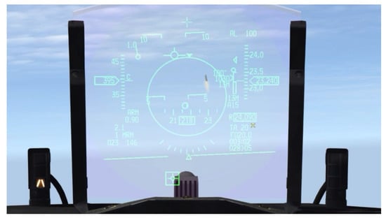
Figure 1.
Simulated situation of the manned fighter’s HUD in the attack guidance state in the BVR air combat.
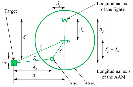
Figure 2.
Schematic diagram of the manned fighter’s HUD in the attack guidance state in the BVR air combat.
In Figure 2, the plus sign, the W-shaped symbol, and the square symbol represent the longitudinal axis direction of the BVR AAM, the longitudinal axis direction of the fighter, and the target, respectively. Furthermore, the large green circle is the allowable steering error circle (ASEC), which is always going to be a circle with a plus sign at the center and a variable radius. The small green circle is the attack steering cue (ASC), which is the best direction to launch the BVR AAM. and are the pitch angle and the azimuth angle of the target relative to the longitudinal axis of the fighter, respectively. and are the pitch angle and the azimuth angle of the ideal aiming point based on the longitudinal axis of the fighter, respectively. refers to the off-axis angle of the AAM. is the lead angle for ideal aiming, which consists of the horizontal component and the vertical component . Besides, the aiming error angle is , where is the setting angle of the AAM.
In the BVR attack guidance state shown in Figure 2, the mission of the pilot is to continuously control the fighter so that the ASC overlaps with the plus sign. In other words, let the ASC be located at the center of the ASEC, and then it is the ideal aiming state with zero aiming error angle. However, as the maneuvering magnitude of the target increases, the magnitude of ASC change also increases. It is inefficient for pilots to perform attack guidance for aiming by manually controlling the fighter, which is also easy to lose the best launch opportunity and obviously not suitable for autonomous UCAVs. To realize high-precision and autonomous attack guidance for UCAVs, it is necessary to make the designed attack guidance system has high dynamic response performance, and the aiming error angle needs to be stable within the specified milliradian range within a certain duration.
Before modeling, several assumptions that simplify the problem to a certain extent without losing practicability are listed:
- The UCAV can obtain real-time status information of the target;
- Ignore the attack angle and the sideslip angle of the UCAV;
- Suppose the setting angle of the AAM is zero.
2.2. The Motion Model of the UCAV
Firstly, the engagement geometry relationship is established in three-dimensional space, as shown in Figure 3.
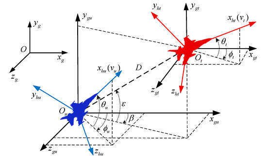
Figure 3.
Engagement geometry relationship between the UCAV and the target.
The following coordinate systems are involved in Figure 3, , , , , and , which represent the geographic coordinate system, the concomitant inertial coordinate system of the UCAV, the trajectory coordinate system of the UCAV, the concomitant inertial coordinate system of the target, and the trajectory coordinate system of the target, respectively. and are the inclination angle and the deflection angle of line-of-sight of the UCAV, respectively, and D is the distance between the UCAV and target.
The UCAV is modeled as a three-degree-of-freedom, point-mass model in three-dimensional, which can be described by and , and details are as following:
where the state vector refers to and to the initial state vector. and refer to the horizontal coordinates and to the altitude of the UCAV in the geographic coordinate system. is the velocity of the UCAV and g is the gravitational acceleration. and are the flight path angle and the heading angle of the UCAV, respectively. The control vector refers to , where , , and are the required control overload components of the corresponding axis in the trajectory coordinate system for the UCAV. is given by the designed attack guidance system.
The control overload constraint model of the UCAV is designed as
where and is the maximum available overload of the UCAV in the normal direction. , and are the actual control overloads of the UCAV. The target motion model similar to that of the UCAV is described by and , where and . The corresponding parameters definition in the motion model of the target is the same as that in the UCAV.
2.3. The Aiming Model of BVR Attack Fire Control
Consider the aiming geometry diagram of the UCAV in the attack guidance state in the BVR air combat as shown in Figure 4.
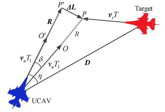
Figure 4.
Schematic diagram of the aiming geometry of the UCAV in the attack guidance state in the BVR air combat.
The flight trajectory pointing to the ideal aiming point P from the current position of the UCAV is the ideal attack guidance trajectory in the state of complete aiming. It means that the UCAV flies a time of along the correct direction at the current velocity , launches the BVR AAM at the point O, and then the AAM hits the point P after flying a distance of R along the ideal straight line trajectory. At the same time, the target has just reached the point P after flying at the velocity for a time of T.
However, in the actual attack guidance process, there is always a deviation between the actual velocity vector of the UCAV and the ideal attack guidance trajectory, that is, the deviation vector shown in Figure 4. Suppose the actual velocity vectors of the target is , and is the distance vector pointing to the target from the current position of the UCAV. The UCAV launches the AAM at the point after flying a time of along the direction of . If the AAM still flies along the ideal distance vector , then the hit point is . The vector pointing from to P is . The angle between and the ideal attack guidance trajectory is the aiming error angle , and the lead angle of the UCAV is , where . Besides, under the assumptions in this paper, and correspond to the angles in Figure 2.
Based on this, the aiming vector equation can be obtained as
where . R and are the ideal attack range and the corresponding average velocity along the ideal straight line trajectory of the AAM, which are both preset according to the missile performance. To facilitate the projection decomposition calculation of the deviation vector, is represented as
The projection of on the trajectory coordinate system of the UCAV is decomposed to obtain three deviation components on the corresponding axes, , , and , that is
where and are the projections of and on the three axes of the geographic coordinate system, respectively. is the transformation matrix from the geographic coordinate system to the trajectory coordinate system of the UCAV, which is given by
By changing the attack guidance time of the UCAV, it can always make , thus the full attack time T can be obtained as
Therefore, and can be obtained by combining Equations (5) and (7). Since , the deviation vector is perpendicular to the axis of the trajectory coordinate system of the UCAV. Consequently, the aiming error angle components, and can be expressed as
The calculation of the aiming error angle components mentioned above takes into account not only the target position and relative motion but also the ideal attack range and the average velocity factors related to the AAM performance. By using them to guide the autonomous attack process for the UCAV, the integrated control of flight control, fire control and weapon system can be realized, so as to improve the autonomous combat effectiveness of the UCAV effectively.
3. Solution Algorithm Design
As previously mentioned, to meet the requirements of high timeliness and high precision for the attack guidance when intercepting high maneuvering targets, the designed attack guidance system needs to calculate corresponding flight controls parameters within a millisecond level period, and the aiming error angle also needs to be stable within the specified milliradian range within a certain duration. In other words, in view of the mathematical models in the previous section, an online autonomous attack guidance system is expected, which can efficiently map from aiming information, , , , and to required overloads and . The architecture of the autonomous attack guidance system is shown in Figure 5. To address this problem, an adaptive fuzzy guidance controller based on the MPC framework is proposed in this section.
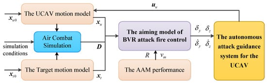
Figure 5.
Architecture of the autonomous attack guidance system.
3.1. MPC Framework
MPC is a popular control strategy in which a model is considered for predicting the future behavior of a plant over a prediction horizon, which adopts an online optimization method to determine the future control effect through the optimization of a certain performance index [35,36]. The control input of each time step of MPC is solved according to the latest state optimization. The main advantage of this strategy is that it is suitable for the optimal control of constrained nonlinear systems and can effectively reduce the accumulation of uncertainties.
The optimal control model of the online autonomous attack guidance system in each time step can be described by
subject to
where , h refers to the time step and k to the step counter. and are the initial state vectors of the UCAV and the target in , respectively. Furthermore, the control constraint in Equation (12) refers to Equation (2). The terminal constraint in Equation (13) is given by
where is the preset minimum distance, which represents the end condition of attack guidance for the UCAV. To reduce the aiming error angle, the performance index in is of the form
The idea of applying the MPC framework to the UCAV autonomous attack guidance is as follows: Firstly, the target motion state of the next time step is predicted according to the motion state of the target measured in the previous time. The UCAV motion state of the next time step is calculated with a certain control vector. Then, the predicted aiming error angle of the next time step is obtained, which is taken as the performance index in Equation (9). Finally, the adaptive fuzzy guidance controller below is used for iterative optimization to obtain the current time step control vector online that makes the performance index optimal. The algorithm schematic diagram of the MPC framework is shown in Figure 6.
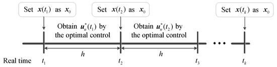
Figure 6.
Algorithm schematic diagram of the MPC framework.
The UCAV motion state is calculated and updated according to the model in Equation (1). Although the target’s maneuver in the future is unknown, the control vector of the target in the previous time step can be calculated through the motion state measured at the previous time. To reduce the algorithm complexity and improve the computational efficiency, this study directly takes as the predicted control vector in the next time step , where , and the components are given by
By substituting the obtained from the above prediction model into the target motion model, the predicted motion state of the target at can be obtained.
The calculation steps of the UCAV autonomous attack guidance using the MPC framework are as follows:
- (1)
- Initialize the motion states of the UCAV and the target, and . Preset the ideal attack range R and the corresponding average velocity of the BVR AAM. Moreover, initialize the aiming error angle and its rate of change, , , , and .
- (2)
- Through the prediction model in Equation (16), the predicted control vector of the target in the next time step and the predicted motion state of the target at can be obtained.
- (3)
- Based on the motion states of the UCAV and the target at the current moment, and , the aiming model of BVR attack fire control in Equation (8) is used to calculate the current aiming error angle, and . Besides, and can be obtained by the variation of the aiming error angles in the last two time steps. Then, with , , and as inputs, the adaptive fuzzy guidance controller in the below is used to generate the control vector , where is kept to zero during the attack guidance process. Thus the motion state of the UCAV at can be obtained.
- (4)
- Based on the motion states of the UCAV and the target at the next time step, and , the predicted aiming error angle information at , , , , and can be obtained by the same method as the previous step.
- (5)
- If and meet the high-precision aiming condition, that iswhere is the maximum allowable aiming error angle under high-precision aiming condition. Other than that, or the number of iteration optimization reaches a preset number G. Then take as the control vector of the current time step to guide the UCAV. Otherwise, assign , , , and to , , and in turn, and return to the Step (3).
- (6)
- If the current distance between the UCAV and the target meets the terminal constraint in Equation (13), then the calculation is finished. Otherwise, update the motion states of the UCAV and the target, and return to the Step (2).
3.2. Adaptive Fuzzy Guidance Controller
For the Step (3) in the above MPC framework, a UCAV attack guidance controller based on the adaptive fuzzy control method [33,34] is designed. Based on the optimal control model in Equation (9), the adaptive fuzzy guidance controller iteratively optimizes the control vector that makes the performance index continuously decrease in each time step, and realizes the approximate optimal control in each time step under the constraint of specified iteration times or high-precision requirements. The main advantage of this algorithm is that it has adaptivity for parameters, which reduces the dependence on artificial expertise and improves the adaptability to uncertain factors. Compared with intelligent optimization algorithms, the algorithm complexity is reduced and the convergence and timeliness are improved.
Since the algorithm of the adaptive fuzzy guidance controller in the horizontal direction is similar to that in the vertical direction, only the vertical direction is taken as an example for modeling in this paper. Firstly, based on the aforementioned aiming model of BVR attack fire control, the attack guidance model in the vertical direction is set up for
where f and b are an unknown function and an unknown positive constant, respectively. Obviously, the aiming error angle instruction in the ideal aiming state is , and . Therefore, the error vector is defined as
To asymptotically converge to zero, that is, when ; set , and let all solutions of the polynomial lie on the left half of the complex plane. Therefore, the control law in the vertical direction is designed as
where .
The principle of the adaptive fuzzy guidance controller is to design a feedback controller and an adaptive law of adjusting parameters based on the fuzzy system to make the output track the ideal instruction as far as possible. Thus the adaptive fuzzy guidance controller in the vertical direction is expressed as
where refers to a fuzzy system and to an adaptive parameter set. For ease of presentation, let and . Firstly, fuzzy sets are defined for the input variable , where and . is constructed with rules that in the form of
Then, product inference engine, singleton fuzzifier, and center average defuzzifier are used to design , that is,
where is the corresponding fuzzy membership function, is the adjustable free parameter and is placed in the set . Therefore, can be described by
where is the dimensional vector, and its th element is given by
In combination with Equations (18)–(21), it can be obtained that
where and . The optimal parameter and the minimum approximation error are respectively defined as
Therefore, Equation (26) can be expressed as
Based on this, the Lyapunov function is define as
where is a positive constant and is a positive definite matrix that satisfies the Lyapunov equation, that is,
where is an arbitrary positive definite matrix with . In combination with Equation (29), the derivative of V can be obtained as
where is the last column of . According to Equation (32), the adaptive law can be designed as
Therefore, can be sufficiently small by designing a fuzzy system with enough rules, and is satisfied, thus making .
Similar to the above process, the UCAV adaptive fuzzy guidance controller in the horizontal direction and its adaptive law can be obtained as
Based on this process, the algorithm flowchart of the adaptive fuzzy guidance controller is shown in Figure 7.
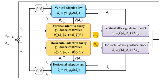
Figure 7.
Algorithm flowchart of the adaptive fuzzy guidance controller.
3.3. Algorithm Pseudocode
Based on the above models and algorithms description, the algorithm pseudocode of the autonomous attack guidance with high aiming precision for UCAV in the BVR air combat is illustrated as Algorithm 1.
| Algorithm 1: The autonomous attack guidance with high aiming precision. |
 |
4. Simulation and Analysis
To validate the accuracy of models and the effectiveness of the algorithms in this study, three simulation experiments are performed in this section, and simulation results are analyzed according to several evaluation indexes. Firstly, all initial parameters used in simulations are given in the following Section. Then, for situations of three different typical maneuvers performed by the target, classical discrete PID control method [28], AFC method, and the method proposed in this study are respectively used to solve the aforementioned UCAV attack guidance model, and the guidance effects are compared and analyzed.
4.1. Simulation Settings
The algorithm parameters, operating environment parameters, and initial model and motion state parameters are given as follows.
Parameters of the algorithm are set as following: , , , , , . The same parameters are set for the adaptive fuzzy guidance controller in both horizontal and vertical directions, i.e., , , , . Both , and are initialized to all-zero matrices. The fuzzy membership functions of , , and are set as follows: , , , , , .
The initial motion states of the UCAV and the target are set as shown in Table 1.

Table 1.
The initial motion states of the UCAV and the target.
Other model parameters are set as , , . Besides, as comparison algorithms, in the classical discrete PID control method [28], based on empirical parameter adjustment, the control parameters in the horizontal and vertical directions are set as , , , where the system control errors are and . The parameter settings in the AFC method are the same as those in the method proposed in this study. The AFC method does not perform the MPC framework and only calculates the control vector once in each time step. Furthermore, the motion states of the UCAV and the target are all updated through the fourth-order Runge–Kutta method.
To further quantitatively validate the effectiveness of the proposed method, the mean aiming error angle , the duration of high-precision aiming , and the mean actual control overload are designed as evaluation indexes to perform quantitative comparison and analysis on the above three methods. and can be calculated, respectively, by
where and refer to the initial and the termination time, respectively. is the sum of time steps that satisfy the condition of in the whole process of attack guidance.
Furthermore, all simulation experiments were performed in MATLAB R2012a environment on a PC with Intel Core i7-2.5GHz CPU and 4GB memory.
4.2. Simulation Experiment 1
In this simulation experiment, the motion mode of the target is set as a horizontal uniform linear motion. Set , , and . Based on the method proposed in this study and the above simulation settings, the simulation results are shown in Figure 8, Figure 9 and Figure 10.
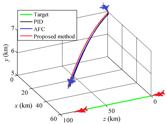
Figure 8.
Attack guidance trajectories for the horizontal uniform linear motion of the target.
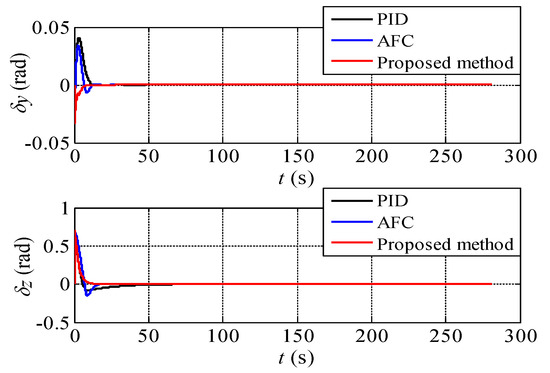
Figure 9.
The aiming error angles of the UCAV during the process of attack guidance.
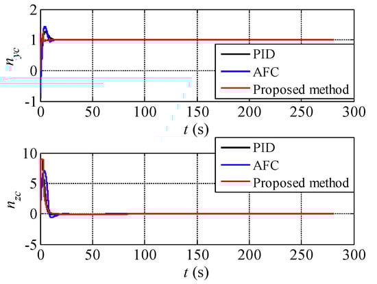
Figure 10.
The actual control overloads of the UCAV during the process of attack guidance.
It can be seen from Figure 8 that the three methods all generate correct attack guidance trajectories for the UCAV. In Figure 9, the aiming error angles of the three methods in both horizontal and vertical directions can reach to zero quickly and remain stable. Since the target moves in a straight line with uniform velocity, the three methods are easy to form a stable aiming state. Besides, combined with Figure 10, it can be further seen that after the initial maneuvering and aiming, the UCAV is in the attack guidance state of approximate linear trajectory all the time, i.e., and . On the whole, in this simulation experiment, there is little difference between the three methods in the attack guidance effect.
Comparisons of quantitative evaluation indexes of the three methods in simulation experiment 1 are shown in Table 2.
Table 2.
Comparisons of quantitative evaluation indexes of the three methods.
It can be seen from the data in Table 2 that the index of the proposed method is slightly better than the AFC and the PID method successively. Moreover, the proposed method also provides a slightly longer duration of high-precision aiming with slightly less control overload. However, since the target does not maneuver, this superiority is not obvious. Through simulation experiment 1, the correctness of the proposed models and the feasibility of the proposed method are preliminarily verified.
4.3. Simulation Experiment 2
In this simulation experiment, the motion mode of the target is set as a periodic turning and climbing motion, which is a typical tactical maneuver in the BVR air combat. Set , , and , where t is the simulation time. Based on the method proposed in this study and the above simulation settings, the simulation results are shown in Figure 11, Figure 12 and Figure 13.
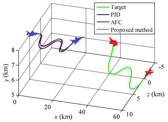
Figure 11.
Attack guidance trajectories for the periodic turning and climbing motion of the target.
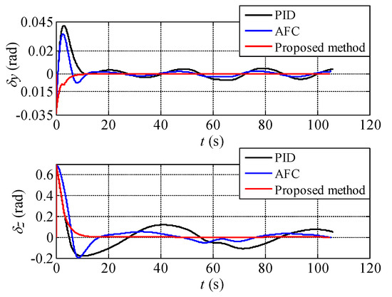
Figure 12.
The aiming error angles of the UCAV during the process of attack guidance.
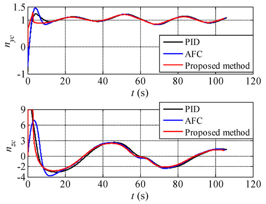
Figure 13.
The actual control overloads of the UCAV during the process of attack guidance.
As can be seen from Figure 11, the three methods can still generate correct attack guidance trajectories as the target is maneuvering in three dimensions. The trajectories are roughly similar with a certain difference. It can be clearly seen from Figure 12 that the proposed method can rapidly reduce the aiming error angle and stabilize it near zero with little oscillation. By contrast, the other two algorithms have various degrees of aiming error angle oscillation with target maneuvering. The aiming error angle in the horizontal direction is obviously larger than that in vertical direction because of the maneuver magnitude of the target. Besides, the variation amplitude and trend of control overload of the three methods are roughly similar (see Figure 13).
Comparisons of quantitative evaluation indexes of the three methods in simulation experiment 2 are shown in Table 3.
Table 3.
Comparisons of quantitative evaluation indexes of the three methods.
As can be seen from the data in Table 3, the proposed method is obviously superior to the PID and the AFC method in terms of evaluation indexes of and . In other words, its aiming efficiency is relatively higher and it can provide longer high-precision aiming time for the UCAV. Specifically, the proposed method has around 87 s and 70 s more high-precision aiming time than the PID and the AFC method respectively. Moreover, based on the above advantages, the control overload cost of the proposed method is also slightly less than that of the other methods. Through simulation experiment 2, the effectiveness and superiority of the proposed method are further verified.
4.4. Simulation Experiment 3
In this simulation experiment, the motion mode of the target is set as the barrel roll maneuvering with a high overload, which is one of the most commonly used tactical maneuvers in the BVR air combat. Set , , and . It should be noted that the initial altitude of both the target and the UCAV is set as in this experiment, and other simulation settings remain unchanged. Then the simulation results are shown in Figure 14, Figure 15 and Figure 16.
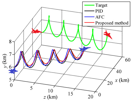
Figure 14.
Attack guidance trajectories for the barrel roll maneuvering of the target.
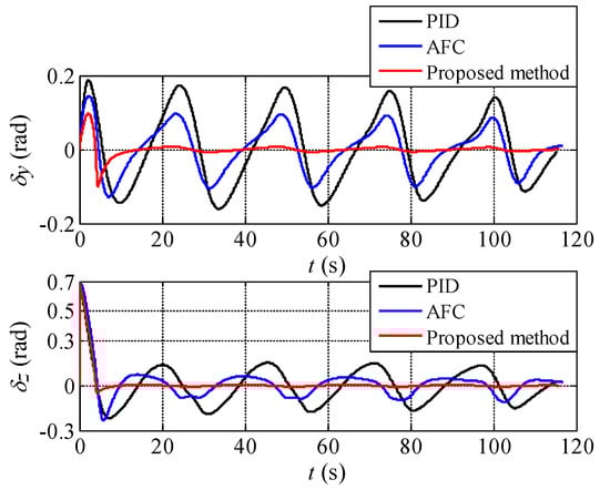
Figure 15.
The aiming error angles of the UCAV during the process of attack guidance.
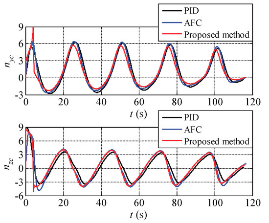
Figure 16.
The actual control overloads of the UCAV during the process of attack guidance.
It can be seen from Figure 14 that the target performs periodic overload maneuver on both horizontal and vertical directions to form a three-dimensional barrel roll trajectory, which significantly improves the difficulty of aiming. The three methods can generate the correct attack guidance which is also approximately the barrel roll trajectory following the target maneuvering. As shown in Figure 15, the aiming error angle generated by the proposed method can be rapidly converged to the vicinity of zero and the oscillation amplitude is very small. In contrast, due to the large maneuver magnitude of the target, the aiming error angle generated by the other two methods is large. In Figure 16, the three methods generate periodic control overload on both horizontal and vertical directions. Besides, the difference of control overload of the three methods is small, in other words, under the approximate control overload condition, the proposed method can generate the attack guidance trajectory with the highest precision and the best stability.
Comparisons of quantitative evaluation indexes of the three methods in simulation experiment 3 are shown in Table 4.
Table 4.
Comparisons of quantitative evaluation indexes of the three methods.
It can be seen from the data in Table 4 that the proposed method has significant superiority over the other methods in terms of evaluation indexes of and . Specifically, the proposed method can provide the UCAV with a high-precision aiming time of about 106 seconds during the attack guidance when the target doing a large overload maneuver, while the other methods are nearly zero. Besides, its control overload cost is also slightly less than that of the other methods.
From the perspective of the engineering application, the timeliness of the proposed method is analyzed below. In this study, the timeliness is evaluated by the average calculation time in a single step, which is the average CPU time required to solve the current control overload in each step over the whole process. A comparison of the timeliness of the three methods in simulation experiment 3 is shown in Table 5.
Table 5.
Comparisons of quantitative evaluation indexes of the three methods.
From the data in Table 5, it can be seen that the proposed method is more time-consuming than the other two methods due to the complexity of the algorithm itself. However, the computation efficiency in a single step of about 0.46 milliseconds can still fully meet the requirements of the airborne computer for the timeliness of fire control computation. Specifically, the timeliness will be further improved, when running on the airborne computers with higher computational performance. Therefore, the proposed method also has the capability of on-line application in terms of timeliness.
Based on the above simulation experiment results, the accuracy of models, and the effectiveness and superiority of the proposed method are verified convincingly. It can be seen that the autonomous attack guidance method in this study has the advantages of adaptivity, high timeliness, and high aiming precision when intercepting the highly maneuvering aerial target.
5. Conclusions and Future Work
In the actual BVR air combat, it is necessary to have a crucial process of attack guidance and aiming of the UCAV to effectively connect the two missions of occupying a superior situation and BVR AAMs’ guidance. The best launching conditions of the BVR AAM can be formed through the process of attack guidance and aiming, which can also give full play to the combat effectiveness of the BVR AAM to the greatest extent.
For the problem of autonomous attack guidance for the UCAV to intercept the highly maneuvering aerial target in BVR air combat. The characteristics of high dynamic, nonlinear, and model uncertainty of the guidance system are fully considered in this paper, and an adaptive fuzzy controller based on the MPC framework is used to design the autonomous attack guidance method. To reduce the predicted aiming error angle based on the target motion prediction information, the algorithm iteratively optimizes and updates the actual guidance control variable online.
Several simulation experiments are used to demonstrate the feasibility and effectiveness of the proposed method, which is compared with the other two classical methods by designed several quantitative evaluation indexes. The simulation results show that the proposed method is very effective for solving the autonomous attack guidance problem, which has the advantages of adaptivity, high timeliness, and high aiming precision when intercepting the highly maneuvering aerial target.
Future research directions will mainly include improving the target motion prediction model, considering the uncertainty of the target motion information, building more real and accurate models, and further enhancing the computational efficiency of the method.
Author Contributions
Conceptualization, Z.Y.; Methodology, Z.Y. and Y.Z.; Data curation, Z.S. and H.P.; Software, Z.Y.; Formal analysis, Z.S. and W.K.; Project administration, H.P. and D.Z.; Writing—original draft, Z.Y.; Writing—review and editing, Y.Z. and K.Z.; Funding acquisition, Z.S. and D.Z. All authors have read and agreed to the published version of the manuscript.
Funding
This work was supported in part by the National Natural Science Foundation of China under Grant 61603299 and Grant 61612385, and in part by the Fundamental Research Funds for the Central Universities under Grant 3102019ZX016.
Conflicts of Interest
The authors declare no conflict of interest.
References
- Shin, H.; Lee, J.; Shim, D.H.; You, D.I. Design of a Virtual Fighter Pilot and Simulation Environment for Unmanned Combat Aerial Vehicles. In Proceedings of the 2017 AIAA Guidance, Navigation, and Control Conference and Exhibit, Grapevine, TX, USA, 9–13 January 2017. [Google Scholar]
- Zhou, D.Y.; Yang, Z.; Zhang, K. Method of Guidance Handover in Beyond-visual-range Coordinated Air-combat for Multi-UCAVs. J. Ballist. 2017, 29, 1–7. [Google Scholar]
- Ernest, N.; Cohen, K.; Kivelevitch, E.; Schumacher, C.; Casbeer, D. Genetic Fuzzy Trees and Their Application towards Autonomous Training and Control of a Squadron of Unmanned Combat Aerial Vehicles. Unmanned Syst. 2015, 3, 185–204. [Google Scholar] [CrossRef]
- Yang, Z.; Zhou, D.Y.; Piao, H.Y.; Zhang, K.; Kong, W.R.; Pan, Q. Evasive Maneuver Strategy for UCAV in Beyond-Visual-Range Air Combat Based on Hierarchical Multi-Objective Evolutionary Algorithm. IEEE Access 2020, 8, 46605–46623. [Google Scholar] [CrossRef]
- Ernest, N.; Carroll, D.; Schumacher, C.; Clark, M.; Cohen, K.; Lee, G. Genetic Fuzzy based Artificial Intelligence for Unmanned Combat Aerial Vehicle Control in Simulated Air Combat Missions. J. Def. Manag. 2016, 6, 1000144. [Google Scholar] [CrossRef]
- Zhou, K.; Wei, R.; Zhang, Q.; Xu, Z. Learning System for Air Combat Decision Inspired by Cognitive Mechanisms of the Brain. IEEE Access 2020, 8, 8129–8144. [Google Scholar] [CrossRef]
- McGrew, J.S.; How, J.P.; Williams, B.; Roy, N. Air-Combat Strategy Using Approximate Dynamic Programming. J. Guid. Control Dyn. 2010, 33, 1641–1654. [Google Scholar] [CrossRef]
- Wang, M.; Wang, L.; Yue, T.; Liu, H. Influence of Unmanned Combat Aerial Vehicle Agility on Short-Range Aerial Combat Effectiveness. Aerosp. Sci. Technol. 2020, 96, 105534. [Google Scholar] [CrossRef]
- Shin, H.; Lee, J.; Kim, H.; Shim, D.H. An Autonomous Aerial Combat Framework for Two-on-Two Engagements Based on Basic Fighter Maneuvers. Aerosp. Sci. Technol. 2018, 72, 305–315. [Google Scholar] [CrossRef]
- Başpınar, B.; Koyuncu, E. Assessment of Aerial Combat Game via Optimization-Based Receding Horizon Control. IEEE Access 2020, 8, 35853–35863. [Google Scholar] [CrossRef]
- Alkaher, D.; Moshaiov, A. Nondominated Strategies for Cautious to Courageous Aerial Navigation. J. Guid. Control Dyn. 2018, 41, 1485–1501. [Google Scholar] [CrossRef]
- Huang, C.Q.; Dong, K.S.; Huang, H.Q.; Tang, S.Q.; Zhang, Z.R. Autonomous Air Combat Maneuver Decision Using Bayesian Inference and Moving Horizon Optimization. J. Syst. Eng. Electron. 2018, 29, 86–97. [Google Scholar] [CrossRef]
- Israelsen, B.; Ahmed, N.; Center, K.; Green, R.; Bennett, W., Jr. Adaptive Simulation-Based Training of Artificial-Intelligence Decision Makers Using Bayesian Optimization. J. Aerosp. Inform. Syst 2018, 15, 38–56. [Google Scholar] [CrossRef]
- Yang, Z.; Zhou, D.; Kong, W.; Piao, H.; Zhang, K.; Zhao, Y. Nondominated Maneuver Strategy Set with Tactical Requirements for a Fighter Against Missiles in a Dogfight. IEEE Access 2020, 8, 117298–117312. [Google Scholar] [CrossRef]
- Lin, D.; Ji, Y.; Wang, W.; Wang, Y.; Wang, H.; Zhang, F. Three-Dimensional Impact Angle-Constrained Adaptive Guidance Law Considering Autopilot Lag and Input Saturation. Int. J. Robust Nonlinear 2020, 30, 3653–3671. [Google Scholar] [CrossRef]
- Zhang, R.; Wang, J.; Li, H.; Li, Z.; Ding, Z. Robust Finite-Time Guidance Against Maneuverable Targets with Unpredictable Evasive Strategies. Aerosp. Sci. Technol. 2018, 77, 534–544. [Google Scholar] [CrossRef]
- Kada, B.; Ansari, U.; Bajodah, A.H. Highly Maneuvering Target Interception via Robust Generalized Dynamic Inversion Homing Guidance and Control. Aerosp. Sci. Technol. 2020, 99, 105749. [Google Scholar] [CrossRef]
- Yang, Z.; Zhou, D.; Pan, Q.; Li, X.Y.; Zhang, K. Research on Adaptive Robust Guidance Law for Passive Homing Missile Against Maneuvering Target. In Proceedings of the 2017 IEEE International Conference on Information and Automation, Macau, China, 18–20 July 2017. [Google Scholar]
- Wu, Z.; Fang, Y.; Fu, W.; Wang, Z.; Ma, W. Three-Dimensional Cooperative Mid-Course Guidance Law Against the Maneuvering Target. IEEE Access 2020, 8, 18841–18851. [Google Scholar] [CrossRef]
- Kaviratna, L.; Costello, M.; Slegers, N. Projectile Fire-Control Algorithm in a Spatially Varying Wind Field. J. Aerosp. Inform. Syst. 2013, 10, 497–512. [Google Scholar] [CrossRef][Green Version]
- Zhou, H.; Zhao, H.; Huang, H.; Zhao, X. Integrated Guidance and Control Design of the Suicide UCAV for Terminal Attack. J. Syst. Eng. Electron. 2017, 28, 546–555. [Google Scholar]
- You, D.I.; Shim, D.H. Design of An Aerial Combat Guidance Law Using Virtual Pursuit Point Concept. J. Aerosp. Eng. 2015, 229, 792–813. [Google Scholar] [CrossRef]
- Blakelock, J.H. Design and Analysis of A Digitally Controlled Integrated Flight/Fire Control System. J. Guid. Control Dyn. 1983, 6, 251–257. [Google Scholar] [CrossRef]
- Liu, J.; Shen, G. A Multi-Strata Hierarchical Structure and Design Method of Integrated Control System. In Proceedings of the 44th AIAA Aerospace Sciences Meeting and Exhibit, Reno, NV, USA, 9–12 January 2006. [Google Scholar]
- Landy, R.J.; Meyer, R.P.; Lambert, R.; Pruess, C.; Greene, K. Integrated Flight and Fire Control: Systbm Integration and Testing and the Role of Onboard Simulation. In Proceedings of the Guidance and Control Conference, San Diego, CA, USA, 9–11 August 1982. [Google Scholar]
- Chen, G.S.; Li, B.J.; Wen, C.Y. The Design Methodology of IFFCS Based on Genetic Algorithms. Control Theory Appl. 1997, 14, 691–696. [Google Scholar]
- Wu, H.X.; Huang, W.; Kang, F.J.; Mao, H.B. Research on Autonomous Intercept Method for UCAV Based on Lead Attack Aiming. Control Theory Appl. 2016, 28, 2246–2253. [Google Scholar]
- Li, C.Y.; Jing, W.X. Fuzzy PID Controller for 2D Differential Geometric Guidance and Control Problem. IET Control Theory A 2007, 1, 564–571. [Google Scholar] [CrossRef]
- Innocenti, M.; Pollini, L.; Turra, D. A Fuzzy Approach to the Guidance of Unmanned Air Vehicles Tracking Moving Targets. IEEE Trans. Control Syst. Technol. 2008, 16, 1125–1137. [Google Scholar] [CrossRef]
- Pablo, G.; Jason, L.F.; Vaios, J.L. Online Evolutionary Swarm Algorithm for Self-Tuning Unmanned Flight Control Laws. J. Guid. Control Dyn. 2015, 38, 772–782. [Google Scholar]
- Wai, R.J.; Lee, J.D.; Chuang, K.L. Real-time PID Control Strategy for Maglev Transportation System via Particle Swarm Optimization. IEEE Trans. Ind. Electron. 2011, 58, 629–646. [Google Scholar] [CrossRef]
- Bao, R.J.; Rong, H.J.; Angelov, P. Correntropy-Based Evolving Fuzzy Neural System. IEEE Trans. Fuzzy Syst. 2018, 26, 1324–1338. [Google Scholar] [CrossRef]
- Lu, Y.K. Adaptive-Fuzzy Control Compensation Design for Direct Adaptive Fuzzy Control. IEEE Trans. Fuzzy Syst. 2018, 26, 3222–3231. [Google Scholar] [CrossRef]
- Hsueh, Y.C.; Su, S.F. Learning Error Feedback Design of Direct Adaptive Fuzzy Control Systems. IEEE Trans. Fuzzy Syst. 2012, 20, 536–545. [Google Scholar] [CrossRef]
- Camacho, E.F.; Alba, C.B. Model predictive control. In Model Predictive Control; Springer: New York, NY, USA, 2013; pp. 131–205. [Google Scholar]
- Gavilan, F.; Vazquez, R.; Camacho, E.F. An Iterative Model Predictive Control Algorithm for UAV Guidance. IEEE Aerosp. Electron. Syst. Mag. 2015, 51, 2406–2419. [Google Scholar] [CrossRef]
© 2020 by the authors. Licensee MDPI, Basel, Switzerland. This article is an open access article distributed under the terms and conditions of the Creative Commons Attribution (CC BY) license (http://creativecommons.org/licenses/by/4.0/).