Abstract
Cellulose is being considered as a suitable renewable reinforcement for materials production. In particular, cellulose based composites are attracting global interest for their unique and intrinsic properties such as strength to weight ratio, dimensional stability and low thermal expansion and contraction. This article investigates the preparation of cellulose pulp fibers with polyamide-6 (PA6) polymer and the effect of fiber orientation within the matrix on the final properties of the biocomposite. Cellulose pulp fibers were melt compounded with PA6 using a thermo-kinetic mixer. Different formulations were prepared and the compounds were manufactured into test samples by injection molding. Mechanical characterization revealed that elastic modulus and the flexural properties increased linearly with the fiber composition. The effect of fiber orientation was examined from square samples out of which individual specimens were cut at different directions with respect to the flow direction. The contributions related to fiber content and effect of fiber orientation on the tensile properties assessed lent positively towards parallel oriented samples (0°) with respect to flow direction. Furthermore, the cellulose network within the biocomposite revealed the superior interfacial properties between the cellulose and PA6 matrix when observed under a scanning electron microscope.
1. Introduction
Cellulose is the most abundant natural polymer in the world. Due to the demand for biodegradable and renewal materials caused due to threats such as global warming and plastic pollution, there has been a tremendous interest during the past decade in biocomposites derived from cellulose and thermoplastic polymers []. From an engineering materials perspective, celluloses form the major load bearing component in wood cell walls with high strength of about ~3 GPa and a potential modulus ~138 GPa with respect to the longitudinal direction []. Extensive research and a number of publications on the terms cellulose and biocomposites have increased drastically in recent years []. Many cellulose reinforced composites have potential applications in the automotive component industry, construction and packaging [,,]. This is due to the sustainability, availability, low density, high specific strength and stiffness of natural fibers which can be compared to that of glass fibers [,,]. To date, almost 50% of a vehicle’s internal parts are made out of polymeric materials and the global average weight of plastic in a modern day passenger vehicle is 105 kg accounting for 10–12% of the vehicle weight []. As government regulations and automotive makers are trending towards fuel economy, high efficiency, and cleaner ways of operating with reduced CO2 levels, the demand for biocomposites is expected to increase [,]. Cellulose fibrils impart improvement in dimensional stability and physical and thermal properties of the cellulose reinforced biocomposites and have excellent potential as a reinforcement material for thermoplastic composites because of their mechanical properties and low thermal expansion coefficient [].
Few studies have been published examining the natural fibers reinforced polyamide-6 (PA6) composites preparation through the injection molding technique for the automotive industry []. Natural fiber reinforced composites are mainly confined to commodity or standard polymers such as polyolefins due to the challenges of high processing temperatures [,,,]. Commonly, polypropylene (PP), polyethylene (PE) and polyoxymethylene are reinforced with natural short fibers and subsequently reveal excellent mechanical properties but these polymers habitually require coupling agents such as maleic anhydride grafted polypropylene (MAPP) and/or dispersing agents such as diglyme, during their preparation processes, respectively [,,,]. Biobased polymer like polylactic acid (PLA) has also been studied as a matrix for natural fibers reinforcement, but PLA-natural fiber composites exhibit poor adhesion at the fiber-matrix interface. Various studies have indicated a decrease in the final properties of the PLA-natural fiber composite and, moreover, have given the thermal characteristics of PLA, it tends to degrade in some compounding processes such as repeated extrusion [,,].
Engineering polymers such as polyamides are in exigency in the automobile industry accounting to their eco-friendly nature. Recent studies emphasizing on increasing the properties of polyamides reinforced with cellulosic materials are promising for our study [,]. Polyamide-11 (PA11) would be an obvious choice of matrix to work on, as 100% bio-based PA11 is commercially available and many investigations published are successful in obtaining composites with high mechanical properties [,]. However, polyamide-6 (PA6) or nylon-6 is a more attractive engineering polymer provided that PA6 is competing with thermoset plastics and metals for ‘’under the hood’’ automotive applications due to their resistance to high temperature, oils and corrosive chemicals, relative strength to weight ratio and recyclability []. The use of natural fibers in PA6 matrix not only provides better physical and mechanical properties to the composite but also there is excellent compatibility between the fibers and the matrix due to the hydrophilic nature of PA6, thus eliminating the need for any coupling agent [,]. In North America, the market size of nylon-6 is estimated to grow as a result of environmental concerns by the plastic industry (Figure 1). This forecast is supported by the increase in demand for environmentally friendly wood based plastic composites. Correspondingly, PA6 has been considered as conventional matrix material for natural fiber-reinforced composites because of its beneficial thermo-mechanical properties [].
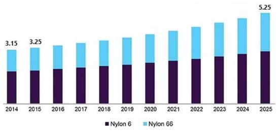
Figure 1.
USA nylon 6 and 66 market size, by product, 2014–2025 (USD Billion) [source: grandviewresearch.com].
With a view to increasing the mechanical properties of the final composite, it is important to understand the mechanics of microstructure of the composite. Von misses′ criteria can be used to deduce that the strength of the composite is limited by the strength of the matrix []. The intrinsic tensile properties of the cellulose fibers can be imparted to the composites if there is qualitative interfacial bonding between the matrix and cellulose fibers. Addition to this, high degree of fiber orientation, fiber dispersion and distribution and shorter processing times are key factors to achieve PA6-cellulsoe composites [].
Melt processing techniques for preparation of natural fibers thermoplastic composites has simplified scaling and shortening time for composite formation []. The morphology and properties of PA6 composites are significantly affected by the type of melt processing technique and also depends on the amount of shear produced []. The most common melt processing technique is the twin screw extrusion process through which high degree of filler dispersion can be obtained and thus, significant reinforcement and greater properties of the composites [,]. However, cycle time is long and optimizing the extruder mixing conditions is a difficult task [], which might lead to thermal degradation of the natural cellulose fibers. Even though there are some limitations such as level of dispersion and distribution or interfacial bonding with the matrix, these limitations can be overcome by melt processing with the Gelimat® mixer []. Gelimat is a compounder/mixer based on the principle of high speed thermo-kinetic mixing. A final compound with excellent dispersion quality can be obtained in one cycle due to the high shear rate generated by the rotor []. The Gelimat equipment and a schematic of the Gelimat mixer is shown in Figure 2. When compared with the twin screw extruder, the Gelimat mixer produces higher dispersion [] and the fiber length remains longer when compared to extruder or internal mixers, consequently improving strength of the composite []. Some studies indicate that several passes are required to obtain a biocomposite using an extruder with satisfactory dispersion level exposing the natural fibers to longer levels of processing time hence prone to thermal degradation [,]. Instead, Gelimat kinetic-mixer compounds at shorter processing time and it helps fibrillation of fibers due to the high shear rate induced [,]. These factors make it very suitable to manufacture extremely time-temperature sensitive biocomposites of cellulose and polymers such as polyamide-6.
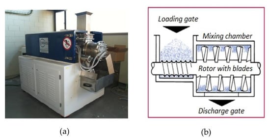
Figure 2.
(a) Gelimat® equipment, and (b) Schematic of Gelimat compounder.
In this study the feasibility of reinforcing PA6 matrix with cellulose fibers by melt compounding with a thermo-kinetic mixer was studied. The thermal degradation temperature of cellulose together with the higher processing temperatures of PA6 are challenges for this study []. PA6 cellulose composites were prepared in the Gelimat mixer and injected to test samples. For analyzing the effect of fiber orientation on the mechanical properties of the composites, a square mold (Figure 3a) for injecting test samples was used and test specimens oriented at different direction with respect to the flow were laser cut from the square samples for all compositions. A simulation of the injection process shows the fiber orientation indicated by color and the scale bar represented by orientation factor (Figure 3b). The alignment of cellulose pulp fibers within the PA6 matrix is dictated by the direction of injection flow and alignment occurs parallel to the flow []. Natural wood pulp fibers with high degree of orientation impart high levels of stiffness to the biocomposite []. Many studies have analyzed the ability of flow stream with fibers to produce homogenous aligned fibrils at the nano and micro scale [,,]. In addition, flow induced alignment has good distribution due to the electrostatic repulsion between the fibrils [,]. Such control of internal morphology gives advantages in expanding the anisotropic properties of biocomposites [].
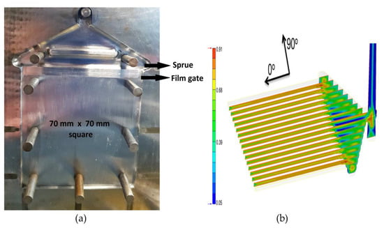
Figure 3.
(a) Square mold, and (b) Flow simulation using Moldex® 3 D with scale bare depicting orientation factor.
2. Materials and Methods
Cellulose was obtained as a commercial product in the form of sheets (>97% cellulose content) by the company Domsjö Fabriker (Örnsköldsvik, Sweden). It is made out of softwood, primarily from the northern parts of Sweden and Latvia. Initially, the thermal degradation temperature of the cellulose pulp fibers was determined by thermogravimetric analysis using a Mettler Toledo TGA851 equipment. Commercially available PA6 (RADILON S 24 E 100 NAT) of 1140 kg/m3 density was purchased from Radici Plastics Iberica SL (Barcelona, Spain) in the form of natural colored pellets. This grade of PA6 has low material viscosity index (125 mL/g) and is suitable for efficient processing with injection molding. A purging agent Ultra Purge 5150 from Chem-Trend (Entzheim, France) was used for cleaning the injection chamber and screw from impurities and also to avoid contamination before the injection process of our composites. The mixing chamber of the Gelimat was cleaned by running it with just the PA6 prior to composite compounding process to avoid contamination.
2.1. Cellulose Pulp-PA6 Composites Preparation
To prepare different compositions of pulp composites, batches of PA6 were dried for 8 h in 80 °C before they were compounded in the Gelimat® (Draiswerke G5 S, Ramsey, NJ, USA) (Figure 2a) to remove the moisture content. Non-dried cellulose sheets were micro-shredded using a paper disintegrator before the melt compounding process.
The mixing chamber of the Gelimat was cleaned with PA6 to avoid contamination. The rotor was set to 300 rpm and non-dry micro-shredded cellulose was introduced first into the mixing chamber through the loading gate (Figure 2b). Non-dried pulp fibers were used to avoid fiber hornification []. Dry PA6 pellets were then introduced and the loading gate was closed. The speed of the rotor blades was then increased gradually up to 2300–2600 rpm to consolidate the mixture to reach a melting temperature of 220 °C thus resulting the mixing time of less than 15–20 s at this temperature. As soon as there was a drop in the current (amperes) drawn by the rotor, compounding of the mixture was completed and then the discharge gate was opened while rotor speed reduced. The discharged compounded mixture collected in the discharge cabin was then carefully rolled flat with the help of a heavy roller and cooled immediately to prevent any thermal degradation. When the flattened composite had completely cooled down to room temperature, it was then broken into smaller pieces to be introduced into the pelletizer and pellets were prepared prior to injection process. Finally, the composites pellets were dried for 8 h at 80 °C before processing them into test specimens using injection molding.
The injection machine (ARBURG AllRounder 220 M) was set to the parameters shown in Table 1 and then injection chamber was purged from contaminants and impurities before starting the injection process for the composites. The composites were injected into a square shaped mold. The injected square samples are shown in the Figure 4a. Later, the test specimens were obtained from the square samples by using a laser cutting. Three different orientations of the test samples were laser cut from the square samples: (i) perpendicular, (ii) parallel, and (iii) at 45° with respect to the injection flow (Figure 4b).

Table 1.
Injection molding parameters for pulp composites.
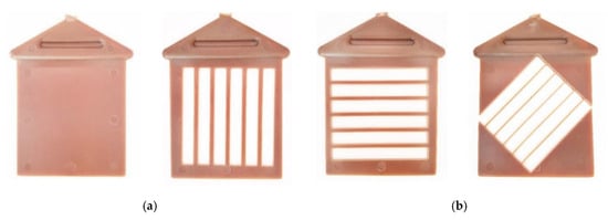
Figure 4.
(a) Square sample with dimension 70 × 70 × 1.5 mm, and (b) Square samples from which oriented specimens are laser cut, (from left to right) parallel (0°), perpendicular (90°) and 45° oriented cut.
2.2. Composite Characterization
2.2.1. Mechanical Testing
Tensile tests were performed using a universal testing machine type InstronTM 1122 (IDM Test, San Sebastián, Spain) fitted with a load cell of 5 kN and operating at 2 mm/min. For tensile testing, specimens were cut to 65 × 6 × 1.5 mm for all compositions at different orientation (0°, 45° and 90°) b). Flexural testing samples were prepared according to the standard ASTM D790 and tensile modulus samples were prepared according to ASTM D638 by using an extensometer (MFA2–Velbert, Germany). All the tests were conducted at room temperature condition (23 ± 2 °C) and relative humidity (50 ± 5%) for dry samples. The same was repeated for 48-h conditioned specimens using a Dycometal (Barcelona, Spain) climatic chamber at 23 °C and 50% relative humidity for 48 h, according to ASTM D618 13 standard, for all composition. A minimum of five samples were tested for each formulation.
2.2.2. SEM Analysis
The morphology of fractured samples was observed under a scanning electron microscope (Zeiss DSM 960A, Jena, Germany) to characterize the interaction between fibers and PA6 matrix. The samples were coated with gold using a sputter prior to measurement and observed at an accelerated voltage of 7 kV.
3. Results and Discussion
3.1. Themogravimetric Analysis of Cellulose Pulp Fibers
Thermogravimetric analysis (TGA) of cellulose pulp fibers provide important information for means to avoid thermal degradation during composite processing. The TGA curve and its first derivative (DTG) curve are shown in Figure 5. About 5% mass loss due to the evaporation of absorbed moisture was observed from 80 °C. The initial mass loss peak started at 320 °C with the maximum mass loss at 346 °C, as shown in the DTG curve (Figure 5). The use of pure cellulose is then beneficial to allow the processing temperature of PA6 of 230 °C without degradation of the pure cellulose fibers. The composites were compounded well under this temperature (220 °C) in the Gelimat and manufactured at an injection temperature not exceeding 230/235 °C, with high injection pressure.
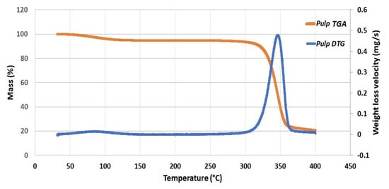
Figure 5.
TGA curve, and DTG for the current cellulose pulp fibers.
3.2. Mechanical Analysis
3.2.1. Tensile Strength of Oriented Specimens
PA6-cellulose pulp composites with cellulose composition of 5, 10, 15, 20, and 25% were prepared, and shown in Figure 6. These pellets were manufactured into test specimens using injection molding. The samples turned light brown with respect to the increasing order of pulp cellulose composition.
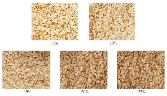
Figure 6.
Cellulose pulp composites pellets indicating their respective cellulose composition prepared from Gelimat mixer and later pelletized prior to injection.
The mean values of tensile strengths of the oriented specimens are shown in the Figure 7a for dry samples and in Figure 7b for 48-h conditioned samples, conditioned at temperature (23 ± 2 °C) and relative humidity (50 ± 5%). The control sample of dry PA6 had a tensile strength of 53.30 MPa. For all formulations, the properties were in accordance to the cellulose fiber orientation inside the composite. It is worth mentioning that 25 wt % of cellulose fiber was the maximum amount of fiber reinforcement affordable for the PA6 matrix. Higher amounts of cellulose fibers were not allowed as the PA6 matrix did not show proper fiber distribution and fiber wrapping along the composite material.
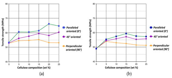
Figure 7.
Tensile strength of oriented samples, (a) dry samples and (b) 48-h conditioned samples.
Parallel oriented specimens (0°) displayed the best results substantiating the wood pulp fiber composites with high orientation in longitudinal alignment have higher mechanical properties []. The tensile strength increased gradually with respect to increase in pulp cellulose composition. The maximum value of 66.17 MPa was obtained for 20% composition followed by 64.76 MPa for 25% composition for dry samples. These tensile strength value corresponds to a 24% higher than the values of the control sample. For 45° oriented samples, the values of tensile strength values were intermediate between 0° and 90° oriented samples with the highest value being 60.44 MPa for dry sample of 25% composition. The 90° oriented samples exhibited the least values as the elongation took place perpendicular to the fibers alignment, this is because of the anisotropic properties defined by morphology of composites []. All the tensile strength values for 48-h conditioned samples showed lower values than the dry ones since the samples absorb moisture during the 48-h conditioning in the climatic chamber and water molecules behave as plasticizer in the course of tensile testing. Here, the maximum tensile strength values were found at 15 wt % cellulose content, with an increment from 48.8 to 59.4 MPa in value with respect to the neat PA6 conditioned. For perpendicular oriented fibers, the strength tends to decrease with the fiber content due to the increase amount of transverse fibers with very low cross section strength that tends to behave as defects along the measurement direction.
3.2.2. Tensile Modulus of Elasticity
The control sample of PA6 for tensile modulus of elasticity (TMOE) test had a value of 3.01 GPa. The control sample subjected to elongation initially responded with elastic deformation, viscoelasticity followed by the yield point. The samples were allowed to deform after yielding resulting in necking and propagation of necking until fracture to measure the elongation at break. The TMOE increased significantly for the composites and its increase is linear to increase in cellulose composition. The maximum TMOE was obtained for 25% composition samples with their values being 4.6 GPa and 4.4 GPa for dry and 48-h conditioned samples respectively (Figure 8b). These TMOE values are equivalent to 53% higher than those of the control sample. The incorporation of cellulose pulp fibers into PA6 matrix restricts the elastic deformation of PA6 resulting in composites with high TMOE [,]. Due to this, pulp cellulose–PA6 composites when subjected to tensile load displayed notably lower strains at yield point when compared to the control sample. The significant drop in strain levels at break is shown in Figure 8a. Higher compositions of cellulose pulp fibers contribute to more relative surface area for the PA6 matrix to adhere to, owing to the high dispersion and distribution of fibers within the matrix imparted during Gelimat compounding. Thereby, forming stronger interfacial bonds and incidentally increasing the tensile strength and TMOE [,].
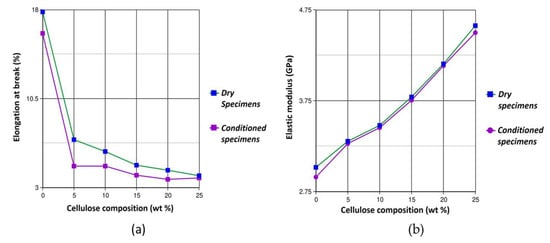
Figure 8.
(a) Elongation at break (indicating low strain at break for composites compared to control sample), and (b) Tensile modulus of elasticity plot for all compositions.
There was a slight decrease of tensile strength from 66.17 MPa to 64.76 MPa from 20% to 25% cellulose composition for the dry samples and 59.40 MPa to 57.29 MPa from 15% to 25% composition for 48-h conditioned samples. Though these were small decrease in the values, this may be due to lack of wetting and interaction between the fibers and PA6 matrix []. In such cases, the lack of interaction weakens the reinforcing effect of the fibers within the PA6 matrix []. The reinforcing effect remain dominant for TMOE and improvements were seen linearly with increase in composition (Figure 8b). This linear increase in stiffness depends on the fiber composition, dispersion and distribution of the pulp fibers within the PA6 matrix [].
Stress strain curves for control sample (neat PA6) and the different compositions of cellulose pulp-PA6 composites deduced from the experimental data are shown in Figure 9. The deformation behavior during elongation for all the samples is observed. Naturally, the presence of fibrils reduces the elongation in the composites when compared to the neat PA6 attributable to the reinforcing effect of cellulose fibers in the matrix []. In addition, increase in the cellulose composition supplements to stiffening the composites. Further, it can be testified from Figure 8a that as fiber composition increases, the strain at the point of deformation decreases thanks to the strong interfacial bonding between fiber and matrix.
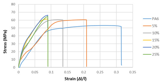
Figure 9.
Stress-strain curves of neat PA6 and cellulose pulp-PA6 composites.
3.2.3. Flexural Resistance and Flexural Modulus of Elasticity
The flexural resistance and flexural modulus of elasticity (MOE) for all the composites are shown in Figure 10. The flexural resistance and flexural MOE for the PA6 control sample were 105 MPa and 2.45 GPa for dry samples and 90.19 MPa and 2.08 GPa for 48-h conditioned samples respectively. The flexural MOE had significant improvements and the flexural resistance had gradual improvements with respect to increase in cellulose composition.
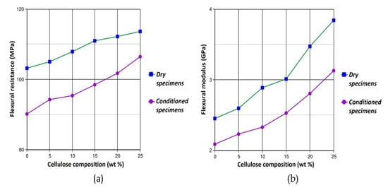
Figure 10.
(a) Flexural resistance and (b) flexural modulus of elasticity (MOE) of the pulp cellulose composites.
The highest values of flexural resistance and flexural MOE were obtained for 25% composition with the values being 113.6 MPa and 3.84 GPa for dry samples and 106.5 MPa and 3.13 GPa for conditioned samples respectively. These values correspond to an 8% increase in flexural resistance (Figure 10a) and 57% increase in flexural MOE (Figure 10b).
3.3. SEM Analysis
The morphology of 5%, 15% and 25% in composition cellulose pulp fiber composites were observed under SEM. The fractured surfaces of samples used for tensile testing were examined to study the interfacial boding between pulp fibers and PA6 matrix sequentially. All the fractured samples were allowed to reach equilibrium weight at room temperature and atmospheric conditions prior to SEM analysis. The SEM micrographs for 25% cellulose pulp-PA6 composite are shown in Figure 11.
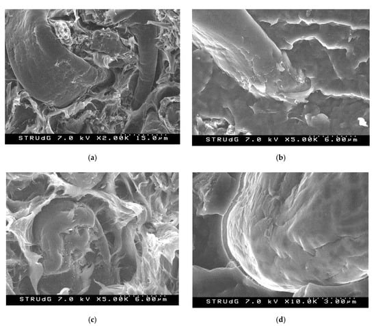
Figure 11.
SEM micrographs of fracture surfaces of 25% cellulose pulp composite tested under tensile load at different magnification levels.
The SEM images reveal that there was good wetting of cellulose pulp fibers within the PA6 matrix, denoting that the cellulose fibril surfaces are saturated by the PA6 matrix. Simultaneously in Figure 11a, it is observed that pulp fiber (micro fibers) were well dispersed and no agglomerations were observed. At higher magnifications (Figure 11b–d), the adhesion between the polymer and the pulp fibers might be due to the chemical affinity between both components favoring the interface compatibility. The hydrophilic nature of PA6 makes the adhesion between pulp fibers and PA6 matrix strong [,]. The attraction between PA6 and cellulose fibers makes dispersion and distribution more effective, as it was validated by the improvements of tensile and flexural properties of the composites. Some authors have explained the chemical interaction between PA6 matrix and cellulose fibers in the partial hydrolysis of PA6 in presence of moisture and high temperature. The moisture content prior to compounding process in (non-dried) fibers aid in interfacial bonding, due to the partial hydrolysis of PA6 caused by moisture at high temperature, generating carboxylic acid end groups which are compatible with the (-OH) groups forming ester bonds []. The reinforcing effect of cellulose materials is determined by the stress transfer through the interfacial adhesion []. The PA6 matrix showed surface distortion characteristic of ductile deformation after reaching to a level that the interfacial adhesion cannot resist and the fibers were broken at the surface. No fiber pullout was observed as seen from Figure 11c.
3.4. Summary
The results obtained from the tensile testing of different oriented samples draw positive conclusions that the composites with parallel fiber orientation with respect to the injection flow exhibit higher values tensile strength. Maximum tensile strength (66.17 MPa) and a maximum TMOE (4.6 GPa) was seen was seen in 20% and 25% cellulose pulp-PA6 composite associating to 24% and 25% increase in values respectively when compared to neat PA6. Similarly, maximum flexural resistance (113.6 MPa) and maximum flexural MOE (3.84 GPa) was attained for 25% cellulose pulp-PA6 composites associating to 57% and 8% higher values than those of neat PA6 respectively.
Previously conducted research on PA6-cellulose materials depicts no major increments in the mechanical properties of the final composite [,]. The tensile and flexural values obtained in this study are without the use of any lubricants or process stabilizers and are comparable to the results of those in the bibliography [,,]. Different cellulosic materials effect the tensile and flexural properties of cellulose based composites due to various factors such as particle size, particle shape, distribution, thermal stability, particle surface morphology and particle surface energy [,]. Lower strain values with the increase in cellulose composition indicate the prominent reinforcing effect of cellulose due to strong interfacial bonding between fibers and PA6 matrix [,]. The adhesion between pure cellulose fibers and PA6 matrix is further demonstrated through SEM analysis. Lack of defects indicate that the compounding method has been effective. Thanks to extreme short processing times, the thermal stresses subjected on the cellulose fibers have negligible degrading effect. This single step, quick compounding process constitutes to high fiber length when compared to studies which involve multiple thermal compounding steps/cycles [,]. This aspect is boon on an industrial level where the promotion of renewable materials is hindered due to complex nature procedures involved in manufacturing biocomposites.
4. Conclusions
Cellulose pulp fibers were used to reinforce PA6 matrix to produce cellulose pulp-PA6 composites from melt compounding with the thermokinetic mixer- Gelimat and injection molding without the use of any coupling agent. The feasibility of conventional manufacturing processes is a very important consideration for industrial level to promote use of renewable materials. This study provides a novel method with a single step compounding procedure and injection molding keeping the industry in mind. The Gelimat minimizes the exposure of cellulose fibers at high temperature inhibiting thermal degradation and the injected samples exhibit high mechanical properties as a consequence of low thermal stresses imposed on the cellulose fibers along with imparting excellent dispersion and distribution of fibers within the PA6 matrix.
Overall, composite compositions of up to 25% in weight of cellulose pulp fiber were prepared and all the formulations showed improved tensile and flexural properties due to the reduced fluidity of PA6 and increased stiffness of the composites when cellulose fibers were incorporated into the PA6 matrix. Also, the SEM micrograph showed good wetting of pulp fibers within the PA6 matrix, without any agglomerations and no pullout of fibers indicating the superiority of the interfacial bonding between the fibers and the PA6 matrix. This demonstrates that the Gelimat equipment is able to compound cellulose-PA6 materials thoroughly with good mechanical properties of the final biocomposite.
This study corroborates that the fiber orientation in injection molded samples is dictated by the forces exerted by the injection flow on the cellulose fiber. The tensile tests of different oriented samples revealed that the fibers aligned in parallel (0°) to the injection flow had the highest values of tensile properties. The flexural tests of parallel oriented samples revealed that the flexural rigidity increases linearly with cellulose composition. TMOE tests revealed low strain at break with respect to cellulose composition indicating the effect of reinforcement. Flow induced natural fibers alignment with high orientation produce biocomposites with high levels of stiffness imparting anisotropic properties to the biocomposite. Moving forward, the potential of this research design can be further explored onto PA6-cellulose nanocomposites and hybrid nanocomposites.
Author Contributions
Conceptualization, P.K.S. and F.V.; methodology, P.K.S. and F.V.; software, P.K.S.; validation, P.K.S. and F.V.; formal analysis, P.K.S. and F.V.; investigation, P.K.S.; resources, P.K.S. and F.V.; data curation, P.K.S.; writing—original draft preparation, P.K.S.; writing—review and editing, P.K.S. and F.V.; visualization, P.K.S.; supervision, F.V.; project administration, F.V.; funding acquisition, F.V. All authors have read and agreed to the published version of the manuscript.
Funding
This research was funded within the Biocomposites Program by Knut and Alice Wallenberg Foundation (Sweden) and the UdG grant (IFUdG 2017).
Acknowledgments
The authors want to thank LEPAMAP Group of the University of Girona (UdG) for helping in the use of laboratory equipment, as well as to the administrative help from the EQATA Department and the OITT service of UdG.
Conflicts of Interest
The authors declare no conflict of interest.
References
- Kargarzadeh, H.; Mariano, M.; Huang, J.; Lin, N.; Ahmad, I.; Dufresne, A.; Thomas, S. Recent developments on nanocellulose reinforced polymer nanocomposites: A review. Polymer 2017, 132, 368–393. [Google Scholar] [CrossRef]
- Saito, T.; Kuramae, R.; Wohlert, J.; Berglund, L.A.; Isogai, A. An ultrastrong nanofibrillar biomaterial: The strength of single cellulose nanofibrils revealed via sonication-induced fragmentation. Biomacromolecules 2013, 14, 248–253. [Google Scholar] [CrossRef] [PubMed]
- Lee, K.Y.; Aitomäki, Y.; Berglund, L.A.; Oksman, K.; Bismarck, A. On the use of nanocellulose as reinforcement in polymer matrix composites. Compos. Sci. Technol. 2014, 105, 15–27. [Google Scholar] [CrossRef]
- Furtado, S.C.R.; Araújo, A.L.; Silva, A.; Alves, C.; Ribeiro, A.M.R. Natural fibre-reinforced composite parts for automotive applications. Int. J. Automot. Compos. 2014, 1, 18. [Google Scholar] [CrossRef]
- Rudeiros-Fernández, J.L.; Thomason, J.L.; Liggat, J.J.; Soliman, M. Characterisation of the mechanical and thermal degradation behaviour of natural fibres for lightweight automotive applications. In Proceedings of the ICCM International Conferences on Composite Materials 2013, Montreal, QC, Canada, 28 July–2 August 2013; Volume 1, pp. 8142–8153. [Google Scholar]
- Njuguna, J.; Wambua, P.; Pielichowski, K. Natural Fibre-Reinforced Polymer Composites and Nanocomposites for Automotive Applications. In Cellulose Fibers: Bio- and Nano-Polymer Composites; Springer: Berlin/Heidelberg, Germany, 2011; pp. 661–700. ISBN 9783642173707. [Google Scholar]
- de Arcaya, P.A.; Retegi, A.; Arbelaiz, A.; Kenny, J.M.; Mondragon, I. Mechanical properties of natural fibers/polyamides composites. Polym. Compos. 2008, 30, 257–264. [Google Scholar] [CrossRef]
- Hakansson, K.M.O.; Fall, A.B.; Lundell, F.; Yu, S.; Krywka, C.; Roth, S.V.; Santoro, G.; Kvick, M.; Prahl Wittberg, L.; Wagberg, L.; et al. Hydrodynamic alignment and assembly of nanofibrils resulting in strong cellulose filaments. Nat. Commun. 2014, 5, 1–10. [Google Scholar]
- Rogovina, S.Z.; Prut, E.V.; Berlin, A.A. Composite Materials Based on Synthetic Polymers Reinforced with Natural Fibers. Polym. Sci.-Ser. A 2019, 61, 417–438. [Google Scholar] [CrossRef]
- Ozen, E.; Kiziltas, A.; Kiziltas, E.E.; Gardner, D.J. Natural fiber blend—Nylon 6 composites. Polym. Compos. 2013, 34, 544–553. [Google Scholar] [CrossRef]
- Dunne, R.; Desai, D.; Sadiku, R.; Jayaramudu, J. A review of natural fibres, their sustainability and automotive applications. J. Reinf. Plast. Compos. 2016, 35, 1041–1050. [Google Scholar] [CrossRef]
- Lee, J.A.; Yoon, M.J.; Lee, E.S.; Lim, D.Y.; Kim, K.Y. Preparation and characterization of cellulose nanofibers (CNFs) from microcrystalline cellulose (MCC) and CNF/polyamide 6 composites. Macromol. Res. 2014, 22, 738–745. [Google Scholar] [CrossRef]
- Annandarajah, C.; Langhorst, A.; Kiziltas, A.; Grewell, D.; Mielewski, D.; Montazami, R. Hybrid cellulose-glass fiber composites for automotive applications. Materials 2019, 12, 3189. [Google Scholar] [CrossRef] [PubMed]
- Peng, Y.; Gardner, D.J.; Han, Y. Characterization of mechanical and morphological properties of cellulose reinforced polyamide 6 composites. Cellulose 2015, 22, 3199–3215. [Google Scholar] [CrossRef]
- Xu, S.; Yi, S.; He, J.; Wang, H.; Fang, Y.; Wang, Q. Preparation and properties of a novel microcrystalline cellulose-filled composites based on polyamide 6/high-density polyethylene. Materials 2017, 10, 808. [Google Scholar] [CrossRef] [PubMed]
- Corrêa, A.C.; de Morais Teixeira, E.; Carmona, V.B.; Teodoro, K.B.R.; Ribeiro, C.; Mattoso, L.H.C.; Marconcini, J.M. Obtaining nanocomposites of polyamide 6 and cellulose whiskers via extrusion and injection molding. Cellulose 2014, 21, 311–322. [Google Scholar] [CrossRef]
- Delgado-Aguilar, M.; Tarrés, Q.; de Marques, M.F.V.; Espinach, F.X.; Julián, F.; Mutjé, P.; Vilaseca, F. Explorative study on the use of Curauá reinforced polypropylene composites for the automotive industry. Materials 2019, 12, 4185. [Google Scholar] [CrossRef]
- Reixach, R.; Espinach, F.X.; Arbat, G.; Julián, F.; Delgado-Aguilar, M.; Puig, J.; Mutjé, P. Tensile properties of polypropylene composites reinforced with mechanical, thermomechanical, and chemi-thermomechanical pulps from orange pruning. BioResources 2015, 10, 4544–4556. [Google Scholar] [CrossRef]
- Tarrés, Q.; Vilaseca, F.; Herrera-Franco, P.J.; Espinach, F.X.; Delgado-Aguilar, M.; Mutjé, P. Interface and micromechanical characterization of tensile strength of bio-based composites from polypropylene and henequen strands. Ind. Crops Prod. 2019, 132, 319–326. [Google Scholar] [CrossRef]
- Espinach, F.X.; Granda, L.A.; Tarrés, Q.; Duran, J.; Fullana-i-Palmer, P.; Mutjé, P. Mechanical and micromechanical tensile strength of eucalyptus bleached fibers reinforced polyoxymethylene composites. Compos. Part B Eng. 2017, 116, 333–339. [Google Scholar] [CrossRef]
- Siakeng, R.; Jawaid, M.; Ariffin, H.; Sapuan, S.M.; Asim, M.; Saba, N. Natural fiber reinforced polylactic acid composites: A review. Polym. Compos. 2019, 40, 446–463. [Google Scholar] [CrossRef]
- Oksman, K.; Skrifvars, M.; Selin, J.F. Natural fibres as reinforcement in polylactic acid (PLA) composites. Compos. Sci. Technol. 2003, 63, 1317–1324. [Google Scholar] [CrossRef]
- Mathew, A.P.; Oksman, K.; Sain, M. Mechanical properties of biodegradable composites from poly lactic acid (PLA) and microcrystalline cellulose (MCC). J. Appl. Polym. Sci. 2005, 97, 2014–2025. [Google Scholar] [CrossRef]
- Venkatraman, P.; Gohn, A.M.; Rhoades, A.M.; Foster, E.J. Developing high performance PA 11/cellulose nanocomposites for industrial-scale melt processing. Compos. Part B Eng. 2019, 174, 106988. [Google Scholar] [CrossRef]
- Alonso-Montemayor, F.J.; Tarrés, Q.; Oliver-Ortega, H.; Espinach, F.X.; Narro-Céspedes, R.I.; Castañeda-Facio, A.O.; Delgado-Aguilar, M. Enhancing the mechanical performance of bleached hemp fibers reinforced polyamide 6 composites: A competitive alternative to commodity composites. Polymers 2020, 12, 1041. [Google Scholar] [CrossRef] [PubMed]
- Oliver-Ortega, H.; Granda, L.A.; Espinach, F.X.; Menez, J.A.; Julian, F.; Mutje, P. Tensile properties and micromechanical analysis of stone groundwood from softwood reinforced bio-based polyamide11 composites. Compos. Sci. Technol. 2016, 132, 123–130. [Google Scholar] [CrossRef]
- Kiziltas, A.; Nazari, B.; Gardner, D.J.; Bousfield, D.W. Polyamide 6–Cellulose Composites: Effect of Cellulose Composition on Melt Rheology and Crystallization Behavior. Polym. Eng. Sci. 2014, 54, 739–746. [Google Scholar] [CrossRef]
- Salem, S.; Oliver-Ortega, H.; Espinach, F.X.; Hamed, K.B.; Nasri, N.; Alcalà, M.; Mutjé, P. Study on the Tensile Strength and Micromechanical Analysis of Alfa Fibers Reinforced High Density Polyethylene Composites. Fibers Polym. 2019, 20, 602–610. [Google Scholar] [CrossRef]
- Rezaee Niaraki, P.; Krause, A. Correlation between physical bonding and mechanical properties of wood–Plastic composites: Part 2: Effect of thermodynamic factors on interfacial bonding at wood–polymer interface. J. Adhes. Sci. Technol. 2020, 34, 756–768. [Google Scholar] [CrossRef]
- Ray, D.; Sain, S. In situ processing of cellulose nanocomposites. Compos. Part A Appl. Sci. Manuf. 2016, 83, 19–37. [Google Scholar] [CrossRef]
- Chavarria, F.; Shah, R.K.; Hunter, D.L.; Paul, D.R. Effect of melt processing conditions on the morphology and properties of nylon 6 nanocomposites. Polym. Eng. Sci. 2007, 47, 1847–1864. [Google Scholar] [CrossRef]
- Karsli, N.G.; Aytac, A. Tensile and thermomechanical properties of short carbon fiber reinforced polyamide 6 composites. Compos. Part B Eng. 2013, 51, 270–275. [Google Scholar] [CrossRef]
- Chavarria, F.; Paul, D.R. Comparison of nanocomposites based on nylon 6 and nylon 66. Polymer 2004, 45, 8501–8515. [Google Scholar] [CrossRef]
- Shah, R.K.; Paul, D.R. Organoclay degradation in melt processed polyethylene nanocomposites. Polymer 2006, 47, 4075–4084. [Google Scholar] [CrossRef]
- Gopakumar, T.G.; Page, D.J.Y.S. Compounding of nanocomposites by thermokinetic mixing. J. Appl. Polym. Sci. 2005, 96, 1557–1563. [Google Scholar] [CrossRef]
- Park, B.D.; Balatinecz, J.J. A Comparison of Compounding Processes for Wood-Fiber/Thermoplastic Composites. Polymer 2004, 18, 425–431. [Google Scholar] [CrossRef]
- López, J.P.; Méndez, J.A.; Espinach, F.X.; Julián, F.; Mutjé, P.; Vilaseca, F. Tensile strength characteristics of polypropylene composites reinforced with stone groundwood fibers from softwood. BioResources 2012, 7, 3188–3200. [Google Scholar] [CrossRef]
- Suzuki, K.; Okumura, H.; Kitagawa, K.; Sato, S.; Nakagaito, A.N.; Yano, H. Development of continuous process enabling nanofibrillation of pulp and melt compounding. Cellulose 2013, 20, 201–210. [Google Scholar] [CrossRef]
- Ho, T.T.T.; Abe, K.; Zimmermann, T.; Yano, H. Nanofibrillation of pulp fibers by twin-screw extrusion. Cellulose 2015, 22, 421–433. [Google Scholar] [CrossRef]
- Uetani, K.; Yano, H. Nanofibrillation of wood pulp using a high-speed blender. Biomacromolecules 2011, 12, 348–353. [Google Scholar] [CrossRef]
- Kamada, A.; Mittal, N.; Söderberg, L.D.; Ingverud, T.; Ohm, W.; Roth, S.V.; Lundell, F.; Lendel, C. Flow-Assisted assembly of nanostructured protein microfibers. Proc. Natl. Acad. Sci. USA 2017, 114, 1232–1237. [Google Scholar] [CrossRef]
- Mittal, N.; Ansari, F.; Gowda Krishne, V.; Brouzet, C.; Chen, P.; Larsson, P.T.; Roth, S.V.; Lundell, F.; Wågberg, L.; Kotov, N.A.; et al. Multiscale Control of Nanocellulose Assembly: Transferring Remarkable Nanoscale Fibril Mechanics to Macroscale Fibers. ACS Nano 2018, 12, 6378–6388. [Google Scholar] [CrossRef]
- Hakansson, K.M.O.; Lundell, F.; Prahl-Wittberg, L.; Söderberg, L.D. Nanofibril Alignment in Flow Focusing: Measurements and Calculations. J. Phys. Chem. B 2016, 120, 6674–6686. [Google Scholar] [CrossRef] [PubMed]
- Kiriya, D.; Kawano, R.; Onoe, H.; Takeuchi, S. Microfluidic control of the internal morphology in nanofiber-based macroscopic cables. Angew. Chemie-Int. Ed. 2012, 51, 7942–7947. [Google Scholar] [CrossRef] [PubMed]
- Santos, P.A.; Spinacé, M.A.S.; Fermoselli, K.K.G.; De Paoli, M.A. Polyamide-6/vegetal fiber composite prepared by extrusion and injection molding. Compos. Part A Appl. Sci. Manuf. 2007, 38, 2404–2411. [Google Scholar] [CrossRef]
- Fernandes, F.C.; Gadioli, R.; Yassitepe, E.; de Paoli, M.A. Polyamide-6 composites reinforced with cellulose fibers and fabricated by extrusion: Effect of fiber bleaching on mechanical properties and stability. Polym. Compos. 2017, 38, 299–308. [Google Scholar] [CrossRef]
- Ku, H.; Wang, H.; Pattarachaiyakoop, N.; Trada, M. A review on the tensile properties of natural fiber reinforced polymer composites. Compos. Part B Eng. 2011, 42, 856–873. [Google Scholar] [CrossRef]
- Faruk, O.; Bledzki, A.K.; Fink, H.P.; Sain, M. Progress report on natural fiber reinforced composites. Macromol. Mater. Eng. 2014, 299, 9–26. [Google Scholar] [CrossRef]
- Feldmann, M.; Bledzki, A.K. Bio-based polyamides reinforced with cellulosic fibres—Processing and properties. Compos. Sci. Technol. 2014, 100, 113–120. [Google Scholar] [CrossRef]
- Aydemir, D.; Kiziltas, A.; Erbas Kiziltas, E.; Gardner, D.J.; Gunduz, G. Heat treated wood-nylon 6 composites. Compos. Part B Eng. 2015, 68, 414–423. [Google Scholar] [CrossRef]
- Tajvidi, M.; Feizmand, M.; Falk, R.H.; Felton, C. Effect of cellulose fiber reinforcement on the temperature dependent mechanical performance of nylon 6. J. Reinf. Plast. Compos. 2009, 28, 2781–2790. [Google Scholar] [CrossRef]
- Xiaolin, X. Cellulose Fiber Reinforced Nylon 6 or Nylon 66. Ph.D. Thesis, Georgia Institute of Technology, Atlanta, GA, USA, December 2008. [Google Scholar]
- Elsabbagh, A.; Steuernagel, L.; Ring, J. Natural Fibre/PA6 composites with flame retardance properties: Extrusion and characterisation. Compos. Part B Eng. 2017, 108, 325–333. [Google Scholar] [CrossRef]
- Peng, Y.; Gardner, D.J.; Han, Y. Drying cellulose nanofibrils: In search of a suitable method. Cellulose 2012, 19, 91–102. [Google Scholar] [CrossRef]
- Peng, Y.; Gardner, D.J.; Han, Y.; Kiziltas, A.; Cai, Z.; Tshabalala, M.A. Influence of drying method on the material properties of nanocellulose I: Thermostability and crystallinity. Cellulose 2013, 20, 2379–2392. [Google Scholar] [CrossRef]
© 2020 by the authors. Licensee MDPI, Basel, Switzerland. This article is an open access article distributed under the terms and conditions of the Creative Commons Attribution (CC BY) license (http://creativecommons.org/licenses/by/4.0/).