Article

The Impacts of Bedding Strength Parameters on the Micro-Cracking Morphology in Laminated Shale under Uniaxial Compression

1
State Key Laboratory for Geomechanics and Deep Underground Engineering, China University of Mining and Technology, Xuzhou 221116, China
2
School of Mechanics and Civil Engineering, China University of Mining and Technology, Xuzhou 221116, China
3
Center for Offshore Research and Engineering, National University of Singapore, E1A-07-03, 1 Engineering Drive 2, Singapore 117576, Singapore
*
Author to whom correspondence should be addressed.
Appl. Sci. 2020, 10(16), 5496; https://doi.org/10.3390/app10165496
Submission received: 20 July 2020 / Revised: 5 August 2020 / Accepted: 6 August 2020 / Published: 8 August 2020
(This article belongs to the Section Earth Sciences)

Abstract

:

Featured Application

The micro-cracking morphology and rock strength of laminated shale could be used to judge whether the shale gas formation is suitable for hydraulic fracturing or not.

Abstract

The micro-cracking morphology in laminated shale formation plays a critical role in the enhancement of shale gas production, but the impacts of bedding strength parameters on micro-cracking morphology have not been well understood in laminated shale formation. This paper numerically investigated the initiation and evolution of micro-cracking morphology with bedding strength parameters in laminated shale under uniaxial compression. First, a two-dimensional particle flow model (PFC2D) was established for laminated shale. Then, the micro-mechanical parameters of this model were calibrated using stress-strain curves and final fracture morphology measured in the laboratory. Finally, the impacts of bedding strength parameters on the uniaxial compressive strength (UCS), crack type and the complexity of fracture network were analyzed quantitatively. Numerical simulation results indicate that the UCS of shale varies linearly with the bedding strength, especially when the shear failure of beddings is dominant. Matrix cracks mainly depend on bedding strength, while the generation of tensile cracks is determined by the shear-to-tensile strength ratio of beddings (STR). The shale with a higher STR is likely to produce a more complex fracture network. Therefore, the bedding strength parameters should be carefully evaluated when the initiation and evolution of micro-cracking morphology in laminated shale formation are simulated.

1. Introduction

The initiation and evolution of micro-cracking morphology in a shale gas reservoir depends not only on the hydraulic treatments but also on the mechanical properties of the rock matrix and beddings. Being different from isotropic rock, finely bedded internal structures in shale formation may result in much more complex anisotropic characteristics and thus may induce different fracturing morphologies. Previous investigations found that laminated structures could affect rock anisotropy. For instance, Cho et al. [1] tested the layered rock specimens from the area of Boryeong, Asan, Yeoncheon, and observed a significant variation of anisotropy in deformation and strength. Fjaer and Nes [2] observed a significant reduction of compressive strength if the shear failure of beddings occurred earlier than matrix failure. Yang et al. [3] found that the joint friction coefficient plays a key role in the residual strength of transversely isotropic rocks rather than the uniaxial compressive strength (UCS) in uniaxial compression. Wei et al. [4] proposed that the anisotropy of the elastic modulus induced by layered structures could affect the estimation of the in-situ stress field. In addition to experimental investigations, Pietruszczak et al. [5,6] investigated the inherent anisotropy of Tournemire shale by introducing a higher-order microstructure tensor into a mathematical model. Their investigations indicated that the deformation and the failure criterion of sedimentary rocks could be described by angle-dependent rock parameters in a theoretical method. The rock strength anisotropy induced by laminated structures is very complex [7,8]. Therefore, the bedding strength parameters should be carefully included in the investigation on the mechanical properties and failure of laminated shale formations.
Macro-fracture or fault morphology has been observed at a geological scale. At this scale, the degree of rock anisotropy induced by layered structures was investigated through long historical environmental impacts and tectonic stress [9,10]. Chen et al. [11] discussed the relationship between the degree of shale anisotropy and tectonic stress and concluded that the prominent triaxial anisotropy of shale appears at a low confining pressure. Liu et al. [12] found that the tectonic stress of rock formation plays a critical role in the pore compressibility of low permeable porous medium, which is directly related with oil saturation. In the laboratory, the mineral composition of Longmaxi shale was found to affect the stress-strain responses of shale [13], and the beddings in shale formation could also affect the pore pressure and crack propagation path during hydraulic fracturing [14]. In engineering, the stability of wellbore is strongly affected by the orientation between the laminated structures and the axis of wellbore [15]. Therefore, bedding strength parameters may vary with geological conditions but strongly affect the mechanical behaviors of laminated shale.
Micro-cracking morphology has been observed in micro-scale experiments. Digital image processing [16], acoustic emission [17] and other advanced techniques have been widely used to observe the initiation and evolution of micro-cracks and their impacts on the mechanical characteristics and fracturing failure of rocks. With the help of a micro computerized tomography (micro-CT) scanner and scanning electron microscopy (SEM) imaging techniques, Liu et al. [18] observed that a lot of micro-tensile cracks occur in uniaxial compression and found that beddings play a key role in the micro-crack propagation in shale formation. Real-time ultrasonic detecting and post-test CT scanning were used to explore the relationship among the total energy and the elastic energy, as well as the dissipated energy in shale formations [19]. These techniques and observations make a great contribution to the understanding of micro-cracking morphology and the fracturing mechanisms. However, scanning of the real-time crack propagation process with high-resolution imaging is extremely expensive. The scanning still cannot capture the contributions of the bedding strength parameters to the initiation and evolution of micro-cracking morphology.
Numerical methods provide a cost-effective alternative to observe the location and failure mode of each crack during the crack propagation process. So far, the crack propagation process of rock has been simulated using numerous approaches, such as the meshless method [20], finite element method [21], extended finite element method [22], finite difference method [23], realistic failure process analysis [24], COMSOL multi-physics [25], MatDEM [26], PB-DEM [27,28] and so on. The effects of mineral composition, the orientation of weak planes, initial fracture characteristics, the elastic modulus, confining pressure, loading rates and many other influencing factors on the mechanical characteristics and fracturing mechanisms of rock materials have been systematically investigated and verified with experimental observations. However, the effects of bedding strength parameters on rock strength and the fracture evolution process still lack comprehensive understanding. Particularly, the influences of beddings strength parameters on the final fracture morphology of shale have been sparingly reported.
This study will investigate the impacts of bedding strength parameters on the micro-cracking morphology in laminated shale formations through micro-mechanical simulations. Firstly, a two-dimensional numerical model within the framework of particle flow code (PFC2D) is built to describe the matrix-bedding microstructure of a laminated shale specimen. Particularly, different micro-constitutive laws are used to describe rock matrix and beddings. Then, the micro-mechanical parameters are calibrated using the stress-strain curves obtained from laboratory measurements. Lastly, the impacts of the tensile and shear strength of beddings on the uniaxial compression strength, crack types and crack fractal dimension of shale specimens are investigated under different dip angles. The numerical simulations reveal the role of bedding strength parameters in tensile cracking and micro-cracking morphology in shale formations. These results are helpful in understanding the relationship between bedding strength parameters and the evolution of a fracture network in shale gas formations. It also makes it possible to predict the complexity of the shale fracture network based on the final fracture morphology of shale under uniaxial compression, which can be used to optimize hydro-fracturing design siting.

2. Microstructure of Laminated Shale Specimen and Micro-Constitutive Models

2.1. Geometric Model and Loading Parameters

A uniaxial compression model for a laminated shale specimen was established. This shale model is 50 mm in diameter and 100 mm in height, which is identical to the suggestion of International Society for Rock Mechanics (ISRM) [29]. Its porosity is set as 5%, which is within the typical range of 2–10% [30,31]. Its density is 2330 kg/m3, which remains unchanged in simulations [32,33]. This two-dimensional model is composed of 9,223 particles (the particles are discs in PFC2D and spheres in PFC3D) and approximately 20,000 contacts. These discs distribute uniformly in a range from 0.6 mm to 1.0 mm in radius.
Figure 1 shows the established shale model under uniaxial compression. This model has two components: rock matrix and beddings. The rock matrix is presented in gray and the beddings are presented in black. The dip angle of beddings is defined as the angle between the bedding and horizontal plane. The bedding is horizontal if the dip angle is 0°. In order to avoid the interference of other factors such as interlocking problems in PFC [34], the perpendicular distance of adjacent beddings maintains a constant at different dip angles of beddings. Based on previous modeling experiences [35], the perpendicular distance between adjacent beddings is set to 16 mm, which is approximately 10 times the disc diameter. The quasi-static loading rate in these numerical compression tests is set as 0.025 m/s, which refers to an investigation of loading rate effects on the cracking behavior of a rock specimen [36]. The loading process will be terminated only if the residual strength decreases to 70% of peak strength.

2.2. Micro-Constitutive Model for Rock Matrix

The simulation in this study is based on the interaction among adjacent discs under uniaxial compression. The motion of a disc follows the Newton’s second law for the translation of mass center and the rotation around the mass center. The force-displacement law among adjacent discs is based on the contact mechanics. The contacts among the discs in a shale matrix are described through the parallel bond model (PBM), which is suitable for simulating the rock deformation and failure process [37]. Figure 2 shows the schematic diagram of this contact. Before the bond is broken, the force and moment at each contact will be updated through the following force-displacement relationship among adjacent discs:
F ¯ n p b = k ¯ n p b A   Δ U n
F ¯ s p b = k ¯ s p b A   Δ U s
M ¯ p b = E I L 1 θ b
where F ¯ n p b , F ¯ s p b are the normal and shear components of contact force and M ¯ p b is the parallel-bond moment; k ¯ n p b , k ¯ s p b represent the normal and shear components of contact stiffness, and the values of these two parameters are decided by the Young moduli of contact, the sum of adjacent disc radius and the stiffness ratio listed in Table 1. A is the cross-sectional area of contact, L is the length of elastic symmetrical beam, which is equal to the sum of the radii between two adjacent discs. and I is the moment of inertia of the cross-sectional area about the neutral axis of the beam. Δ U n , Δ U s are the displacement increments in the normal and shear directions, respectively. They correspond to the extrusion/detachment and slip between adjacent discs. θ b is the relative bend-rotation increment, which corresponds to the rotation of discs.
Each contact may have two failure modes: tensile failure and shear failure. The failure is determined by the stress at the contact point. For the tensile failure, the tensile stress σ ¯ is calculated by
σ ¯ = F ¯ n p b A + β M ¯ p b R ¯ I
For the shear failure, the shear stress τ ¯ is calculated by
τ ¯ = F ¯ s p b A
where R ¯ is the contact length in PFC2D, and β is the moment-contribution factor.
A micro-crack is generated when the contact stress exceeds the strength parameters of the bonded contact. This implies that two failure modes may occur at each contact. For example, a micro-tensile crack of rock matrix (Pbt) occurs if the tensile stress σ ¯ exceeds the tensile strength of rock matrix σ ¯ c p b . This tensile crack detaches the contact, forming an open micro-crack. A micro-shear crack of rock matrix (Pbs) occurs if the shear stress τ ¯ exceeds the shear strength of rock matrix τ ¯ c p b . When shear failure occurs, the parallel-bond moment M ¯ p b and cohesion at the contact disappear and frictional sliding occurs.

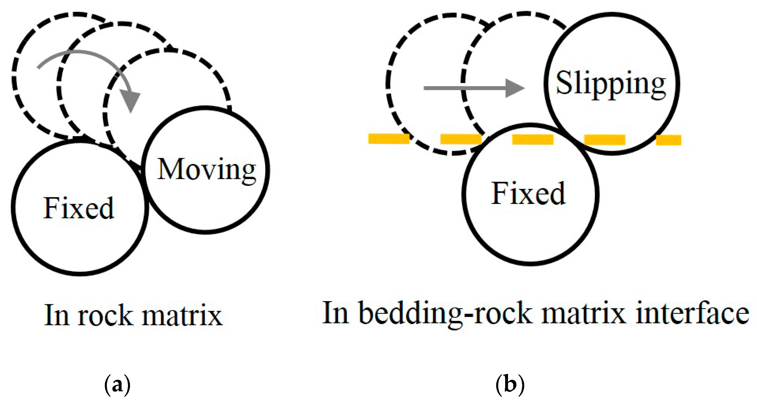
2.3. Micro-Constitutive Model for Bedding

Bedding in shale formation is a special element. This study adopts the smooth joint model (SJM) to simulate the contacts of beddings [38]. The SJM can only deliver contact force. The tensile failure between adjacent discs in the SJM is similar to that in the PBM, but the SJM treats the shear slip between discs in a different way, as shown in Figure 3. The most distinguished feature of the SJM is that the discs along the beddings can overlap and slide across each other, while the discs can only move around one another in the PBM. Further, the dilatancy effect is considered in the shear force of the SJM if shear failure occurs. Therefore, the SJM is suitable for simulating the shear slip of beddings in rocks. The force and stress after failure in the SJM are calculated using the following fundamental algorithm:
F ¯ n s j = Δ F ¯ s s j k ¯ s s j k ¯ n s j tan φ
F ¯ s s j = μ f F ¯ n s j
σ ¯ = F ¯ n s j A
τ ¯ = F ¯ s s j A
In the contact model of the SJM, the normal force F ¯ n s j and shear force F ¯ s s j are oriented to the normal and tangential directions of beddings rather than the original orientation of the contact. k ¯ n s j and k ¯ s s j are the normal and shear stiffness per unit contact area. φ is the dilation angle of beddings.
Micro-tensile crack and micro-shear crack may occur in beddings. A micro-tensile crack of beddings (Sjt) occurs if the tensile stress σ ¯ exceeds the tensile strength of beddings σ ¯ c s j . A micro-shear crack of beddings (Sjs) occurs if the shear stress τ ¯ exceeds the shear strength of beddings τ ¯ c s j . Therefore, shale formation may have four failure modes.

2.4. Complexity Measure of Micro-Cracking Morphology

Micro-cracking morphology in shale formation can be comprehensively measured using the fractal dimension of the crack network. A bigger fractal dimension indicates more complex fracture morphology. Recently, fractal analysis has been successfully used to characterize the pore structures or fracture networks in an investigation of unconventional gas reservoirs [39,40]. The pore structures and fracture complexity of shale gas reservoirs control the capacity of gas flow during hydraulic fracture treatments [41]. According to the simulated final fracture morphology of the shale specimen, the effects of bedding strength parameters on fracture complexity are quantitatively analyzed through crack fractal dimension. The crack fractal dimension is calculated using the box-counting method with the following formula.
D = lim n lg M ( n ) n lg 2
where M ( n ) is the number of boxes containing cracks, and 2 n represents the total number of square boxes which fully cover the binary image.
The calculation procedure is stated below. A binarization algorithm is conducted first before the image segment. After that, the binary image will be covered by 2 n square boxes. By changing the size of the square box, the surface of the binary image (micro-cracking morphology after binarization treatment) can be covered by a different number of square boxes. The total number of square boxes is always an exponential of base two. Among these square boxes, there are M ( n ) square boxes containing cracks. As the box size decreases, the slope is the crack fractal dimension D when lg M ( n ) and n lg 2 are projected in an orthogonal logarithmic coordinate system [42]. In this study, the crack fractal dimension is used to measure the complexity of micro-cracking morphology under different bedding strength parameters. This is to describe the complexity of the crack network.

3. Comparison of Numerical Simulations with Laboratory Measurements

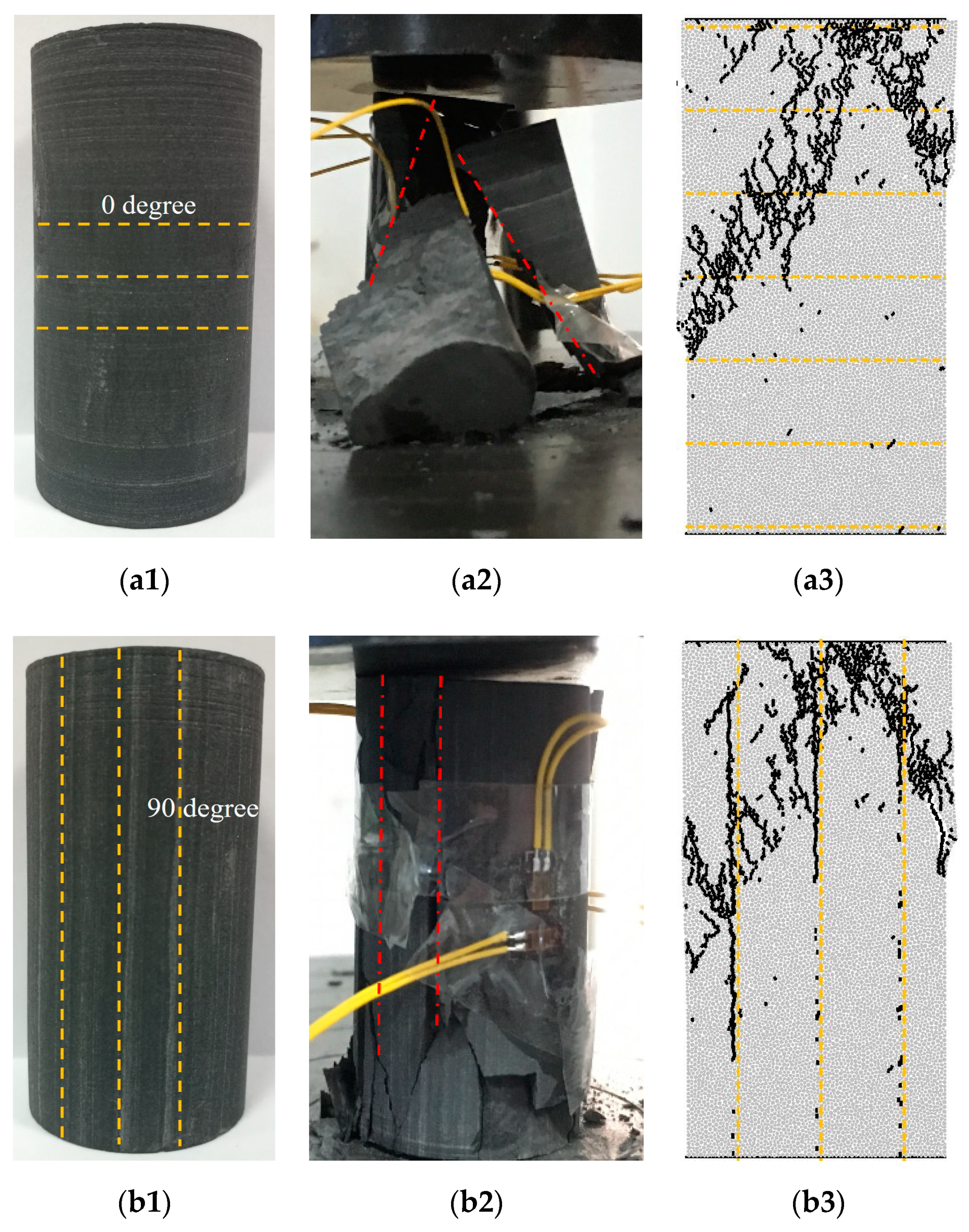
3.1. Experiments in Uniaxial Compression

Two sets of shale specimens (0° and 90°) from Longmaxi formation were physically tested in uniaxial compression (see Figure 4). Each set tested three specimens under the quasi-static loading rate of 0.05 mm/min. These specimens are 25 mm in diameter and 50 mm in height. The specimen dimensions in tests are different from those in numerical simulations. However, they have the same height/diameter ratio (2:1). Fan et al. [43] have proved that internal stress distribution is fairly even and does not change with the size of the rock specimen when the height/diameter ratio is 2:1. This implies that the dimension difference between the tested shale specimen and the simulated shale model does not affect the stress-strain responses and micro-cracking morphology.

3.2. Determination of Micro-Parameters

Some technologies such as the indentation test have been applied to measure the strength parameters of rock minerals in a local area, but it is extremely difficult to obtain the micro-parameters of shale matrix and beddings. In our simulations, all micro-parameters used in the numerical model are calibrated through a trial and error approach. The slope of the stress-strain curve, the peak strength and the macro-fracture morphology of the rock specimens were used as characteristic indicators to calibrate the strength parameters in the numerical model [44,45]. By adjusting the Young’s modulus and stiffness ratio of the particle and contacts, the slope of the simulated stress-strain curve becomes parallel to the laboratory curves [46]. Further, both shear and tensile strengths at the contact are adjusted to match the UCS. The micro-parameters are finally determined when the simulation results match well with the experimental ones.
The stress-strain responses between the laboratory results (after the elimination of discreteness curve) and numerical simulations are compared in Figure 5. Figure 5a shows that the UCS, slope and the evolution process of the simulated stress-strain curves agree well with the experimental ones at the dip angle of 0°. Figure 5b shows some differences between the laboratory and numerical results when the dip angle is 90°, but the simulated peak strength still approaches the average of the experimental ones. Further, the fracture morphology of shale at 0° and 90° is similar between the experiments and simulations, as shown in Figure 6. The calibrated micro-parameters are listed in Table 1 for the rock matrix and in Table 2 for beddings. These calibrated parameters will be used in subsequent simulations. It is noted that the bedding strength is usually weaker than the shale matrix. In this specimen, the bedding strength parameters are about half of the shale matrix after calibration. With these parameters, we will explore the influences of bedding strength parameters on the stress-strain response, the percentage of different crack types and the fractal dimension of micro-cracking morphology in the next section.

4. Micro-Cracking Behaviors of Shale under Different Bedding Parameters

The effects of dip angle and bedding strength parameters on micro-cracking morphology will be explored in the laminated shale formation. Two new indicators are introduced here: the ratio of bedding (including tensile and shear) strength to the datum value for beddings (called joint strength ratio or JSR) and the ratio of shear strength to tensile strength of beddings (called shear-to-tensile strength ratio or STR). These two indicators may comprehensively affect the micro-cracking morphology.

4.1. Effects of Bedding Strength

4.1.1. Stress-Strain Responses and Micro-Crack Evolution

This section mainly explores the impacts of bedding strength on the stress-strain responses and micro-cracking behaviors of shale under uniaxial compression loadings. The JSR in this section was taken as 0.8, 1.0 and 1.2 for both the tensile ( σ ¯ c s j ) and shear strength ( τ ¯ c s j ) of the beddings. Further, the dip angle is taken as 0°, 30°, 60° and 90°.
The stress-strain and crack growth curves of shale are presented in Figure 7 when the JSR is 1.0. When the dip angle is 0°, the axial stress increases linearly with axial strain at the pre-peak strength stage. Figure 7a shows that no micro-cracks are observed until the axial stress is at approximately 85% of the peak strength. After the peak strength of 91 MPa, the axial stress drops abruptly and shows obvious brittle failure. Simultaneously, different types of micro-cracks occur rapidly as the axial stress approaches the peak strength. This was observed by the acoustic emission of shale in the laboratory [47]. The growth rate and quantity of matrix cracks are dominant. Thus, micro-cracks occur mainly in the rock matrix. When the dip angle is 30°, the stress-strain curve has no obvious change in shape (see Figure 7b), but the crack growth rate changes significantly. Particularly, the growth rate of shear crack in beddings increases significantly. At this time, shear cracks of beddings initiate just as the axial stress increases to approximately 60% of the peak strength. This is much earlier than that in the case of a dip angle of 0°. When the dip angle is 60°, the peak strength drops to 44 MPa (see Figure 7c). The shear slip of beddings initiates when the axial stress approaches about 80% of the peak strength and then increases considerably after the peak strength. In this circumstance, the damage of the rock matrix seems negligible. The stress-strain responses and the evolution of micro-cracks at the dip angle of 90° (see Figure 7d) are similar to those at the dip angle of 0°. The matrix failure becomes dominant again. The stress-strain curve changes little in shape but the crack growth curve is different. The shear crack of beddings occurs first and then the matrix crack appears. Therefore, the dip angle is an important parameter to affect the local stress and the evolution of micro-cracking morphology.
Figure 8 summarizes the variations of UCS with the dip angle under different JSR. When the dip angle is 0°, 30° and 90°, the UCS is almost the same. This implies that the dip angle has little impact. Further, the UCS is the lowest at the dip angle of 60° but this UCS also varies with JSR. The UCS increases from 35 MPa to 44 MPa and subsequently to 53 MPa when the JSR increases from 0.8 to 1.0 and then to 1.2, respectively. This growth rate is consistent with the increase of bedding strength. This implies that the UCS of the shale sample is the most sensitive to the bedding strength when the dip angle is 60°. Similar behaviors were observed in uniaxial compression tests [3] and Brazilian splitting tests [9]. This is because the failure pattern was changed. The micro-cracking morphology determines the UCS of shale formation.

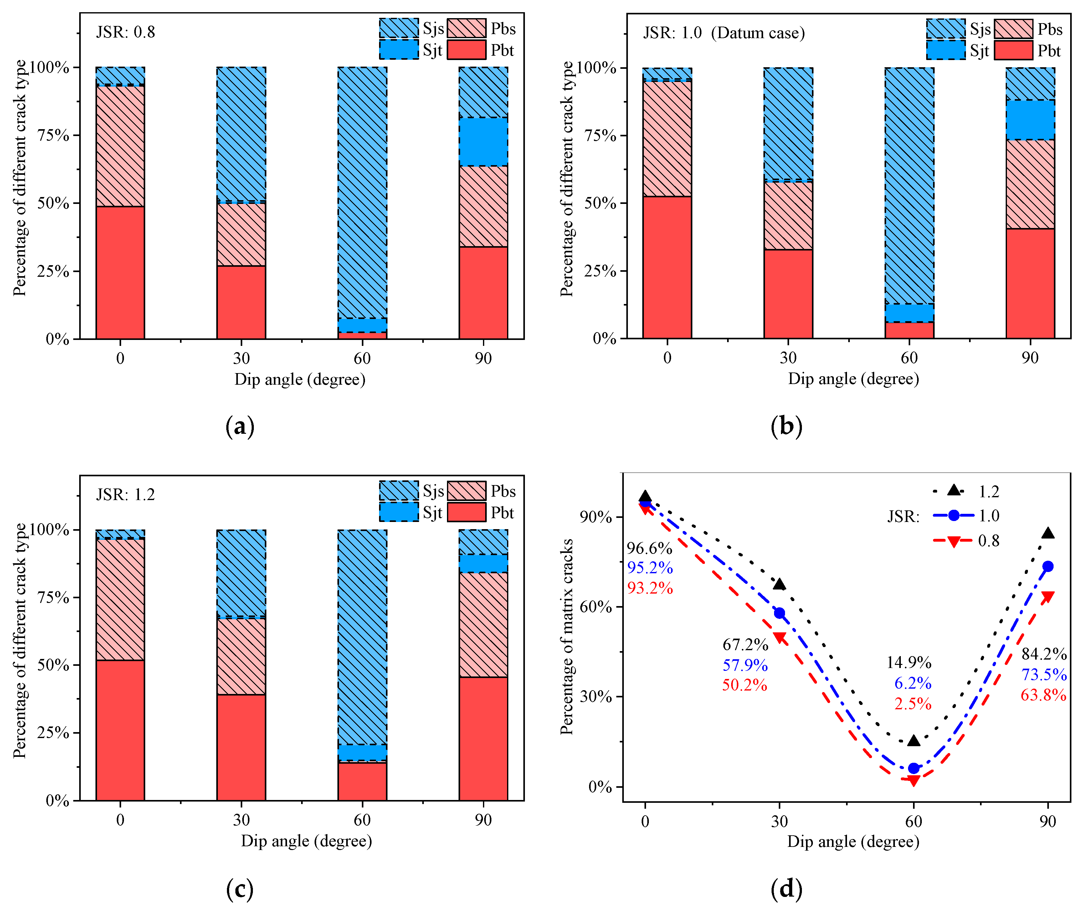
4.1.2. Change of Crack Types

Four crack types are identified in numerical simulations: tensile crack in matrix (Pbt), shear crack in matrix (Pbs), tensile crack in beddings (Sjt), shear crack in beddings (Sjs). This classification is based on the failure mode and location of micro-cracks. For convenient comparison, the percentage of each type of crack is the ratio of the number of those in the same crack type to the total number of micro-cracks at the end of loading process.
The influence of dip angle on the crack type is investigated. The percentage of each type is presented in Figure 9. Figure 9a shows that the percentage of shear cracks in the matrix and beddings (Pbs+Sjs) increases first and then decreases with the dip angle. As the dip angle increases from 0° to 90°, the percentage of shear cracks is 50.6%, 72.2%, 92.2% and 48.3%, respectively. This indicates that the percentage of each crack type varies with not only the dip angle but also the bedding strength. The first three pictures in Figure 9 show that the average ratio of the number of tensile cracks to shear cracks in the shale model is 0.628, 0.758 and 0.776 as the JSR increases from 0.8 to 1.2. This implies that the percentage of tensile cracks in the shale specimen increases with the increase of bedding strength. The impact of the JSR on the percentage of matrix cracks is presented in Figure 9d. The percentage of matrix cracks increases with the increase of bedding strength. A larger bedding strength results in a higher growth rate of the percentage of matrix cracks. For instance, when the dip angle is 60°, the percentage of matrix cracks (Pbt+Pbs) increases from 2.5% to 6.2% and subsequently to 14.9% as the JSR increases from 0.8 to 1.0 and then to 1.2, respectively. The growth rate of matrix cracks becomes larger when the bedding strength increases in uniaxial compression loading. These simulation results indicate that the number of tensile cracks and matrix cracks increases with the increase of joint strength. During the exploration of shale gas, the increasing number of tensile cracks in the shale matrix will facilitate the shale gas transportation during hydraulic fracturing. The increase of tensile cracks (Pbt+Sjt) in fracturing behaviors could also contribute greatly to shale gas production.

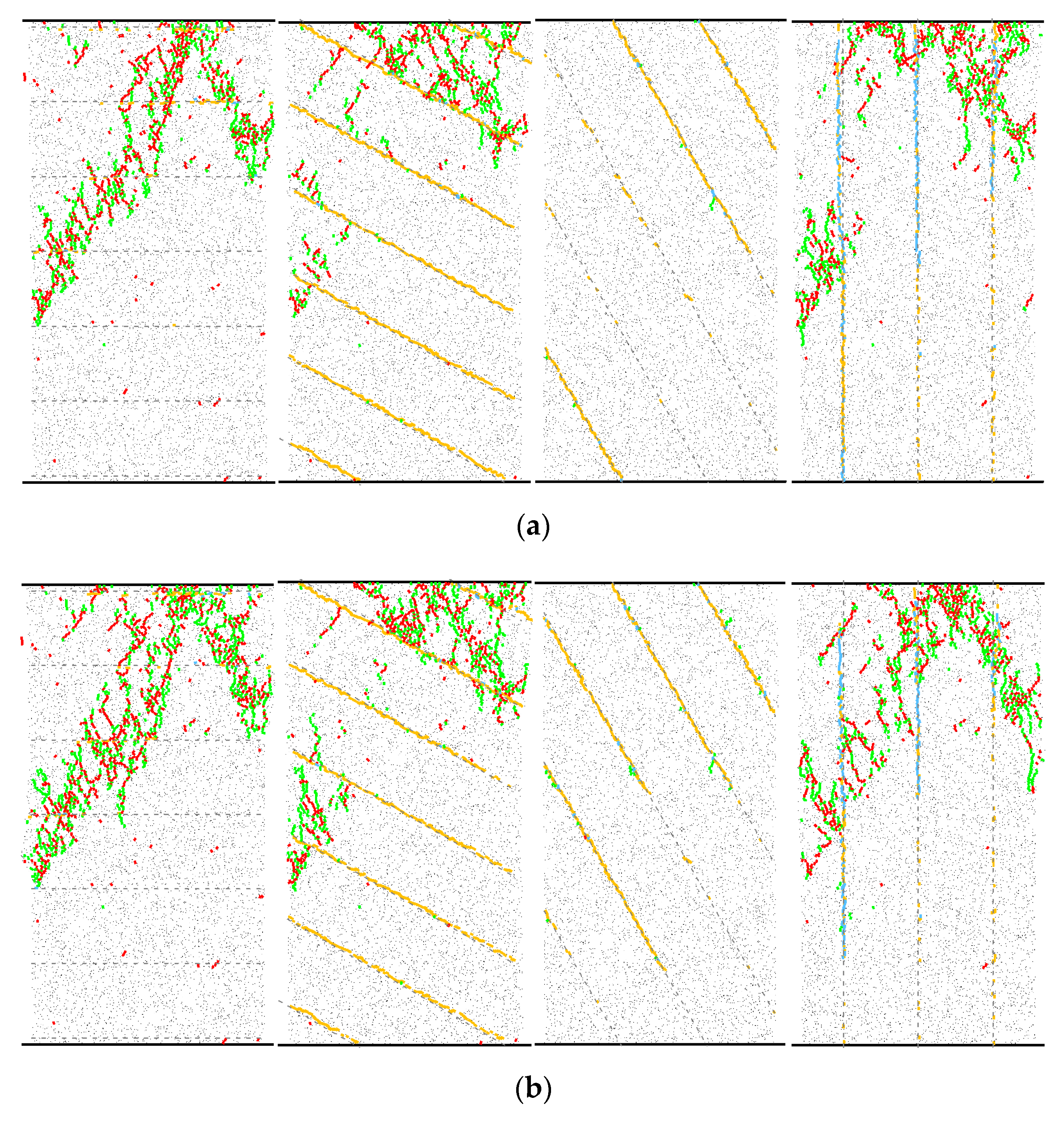
4.1.3. Micro-Cracking Morphology

The final fracture morphology of shale is the accumulation of different micro-cracking modes. Figure 10 presents the variations of fracture morphology of shale specimens with the JSR. These figures show that both dip angle and bedding strength have significant impacts on the final fracture morphology. When the dip angle is 0°, most of the micro-cracks occur in the rock matrix. The matrix cracks initiate from the top of the shale specimen and then cross the beddings along the loading direction. These matrix cracks coalesce into main fractures and then divert to one side of the specimen. The final fracture morphology is consistent with the laboratory observations in Figure 6a. On the micro-scale, the damage of the rock matrix results in the splitting failure of the shale specimen, while the bedding strength only has a local influence in the sub-fractures near the damaged beddings. When the dip angle is 30°, a lot of beddings are in shear-slip failure. This limits the extension of matrix cracks from the top of the specimen. At this time, the shear cracks of beddings decrease more significantly for larger bedding strength, and the matrix cracks extend outward more evidently. This is a combined splitting and bedding sliding failure. When the dip angle is 60°, the failure pattern of the shale specimen transforms from the combined splitting and bedding sliding failure to a pure sliding failure. Only a few matrix cracks emerge near the damaged beddings. As the JSR increases from 0.8 to 1.2, some matrix tensile cracks (Pbt) increase slightly near the sliding beddings. At the dip angle of 90°, a combined tensile-sliding failure of beddings occurs if the JSR is 0.8. As the JSR increases from 1.0 to 1.2, the tensile crack of beddings (Sjt) decreases. The shale specimen fails gradually due to the rock matrix.
The influence of the JSR on micro-cracking morphology is quantitatively analyzed by calculating the average of the crack fractal dimension at different dip angles. As the JSR increases from 0.8 to 1.2, the average fractal dimension of the matrix crack (Pbt+Pbs) is 1.207, 1.268 and 1.281 and the average fractal dimension of the tensile crack (Pbt+Sjt) is 1.225, 1.293 and 1.291, respectively. The growth rate of the fractal dimension decreases gradually with the increase of the JSR. The above analysis shows that the dip angle controls the morphology of the main fracture, while the bedding strength could change the distribution of sub-fractures. To some extent, the increase of bedding strength can enhance the complexity of the sub-fracture distribution.

4.2. Effects of Shear-to-Tensile Strength Ratio of Beddings

4.2.1. Stress-Strain Responses and Micro-Cracking Evolution

The effects of shear-to-tensile strength ratio (STR) on the stress-strain responses and micro-cracking behaviors are analyzed in this section. The tensile strength of beddings σ ¯ c s j was kept to 15 MPa, while the shear strength of beddings was set to 12 MPa, 15 MPa and 18 MPa. Therefore, the STR in this section was set to 0.8, 1.0 and 1.2, respectively. Figure 11 presents the stress-strain curves and crack growth curves with dip angles of 0°, 30°, 60° and 90° when the STR is 1.0. Generally, the stress-strain curves in uniaxial compression have three stages: the linear elastic stage, the plastic deformation stage and the brittle failure stage. They are similar to those in Figure 7. This suggests that both the JSR and STR have a negligible influence on the shape of the stress-strain curves, while the dip angle of beddings makes a difference in the trend of the crack growth curves.
Figure 12 shows that the STR alters the downward trend of the curves for the dip angle of 60°, but the UCS of the shale specimen varies little at other dip angles. When the dip angle is 60°, the UCS increases from 29 MPa to 37 MPa and subsequently to 44 MPa as the STR increases from 0.8 to 1.0 and then to 1.2, respectively. The UCS grows consistently with the increase of the STR.

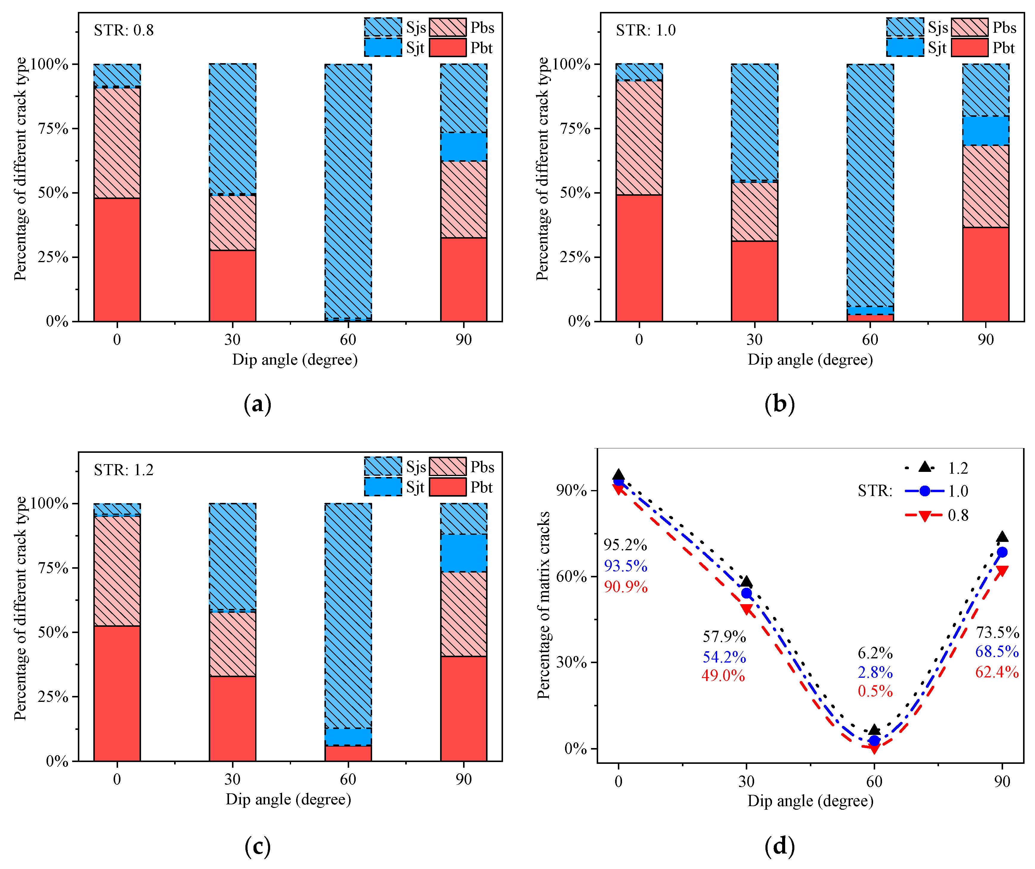
4.2.2. Changes of Crack Type

The STR may affect the crack type. Figure 13 presents the crack types at different STRs. It can be inferred from Figure 13a that the percentage of shear cracks occurring in the matrix and beddings (Pbs+Sjs) is 51.6%, 71.8%, 98.6% and 56.4% when the dip angle is 0°, 30°, 60° and 90°, respectively. The percentage of shear cracks (Pbs+Sjs) is higher than the percentage of tensile cracks (Pbt+Sjt) at all dip angles. If the dip angle approaches 60°, the number of shear cracks of the beddings becomes dominant, and the shale specimen experiences a pure bedding sliding failure. If the tensile strength of beddings ( σ ¯ c s j ) is kept constant, the STR makes a difference in the percentage of each crack type. Further, the average ratio of the number of tensile cracks to shear cracks in the shale specimen increases from 0.530 to 0.608 and subsequently to 0.758 as the STR increases from 0.8 to 1.0 and then to 1.2, respectively. Therefore, the failure mode of the shale specimen is also sensitive to the STR. A larger STR can have a higher percentage of tensile failure. The growth rate of the percentage of matrix cracks is consistent with the increase of the STR. This result is a little different from that induced by the JSR.

4.2.3. Micro-Cracking Morphology

Figure 14 presents the final fracture morphology of shale under different STRs. The variation of the STR hardly changes the fracture morphology if the dip angle is 0°. The failure of the shale specimen mainly occurs in the shale matrix rather than the beddings when the dip angle is 0°. When the dip angle is 30°, a higher STR promotes a cluster generation of matrix cracks rather than outward extension. The matrix cracks mainly occur at the top and the middle of the shale specimen. When the dip angle is 60°, the dominant failure is the shear slip of the beddings, and the variation of the STR only affects the number of sliding beddings. Owing to the constant tensile strength of beddings, the tensile failure zone of beddings is basically unchanged when the dip angle is 90°. Under this circumstance, the tensile-sliding combination failure of beddings gradually transforms into the tensile failure of beddings as the STR increases from 0.8 to 1.2.
The influence of the STR on the complexity of micro-cracking morphology is quantitatively analyzed through the perspective of fractal dimension. As the STR increases from 0.8 to 1.2, the average of the fractal dimension is 1.229, 1.219 and 1.268 for the matrix crack (Pbt+Pbs) and 1.186, 1.242 and 1.293 for the tensile crack (Pbt+Sjt), respectively. The STR cannot play a role in the main fracture morphology, but the increase of the STR can enhance the complexity of sub-fractures, especially when the STR is larger than 1.0.

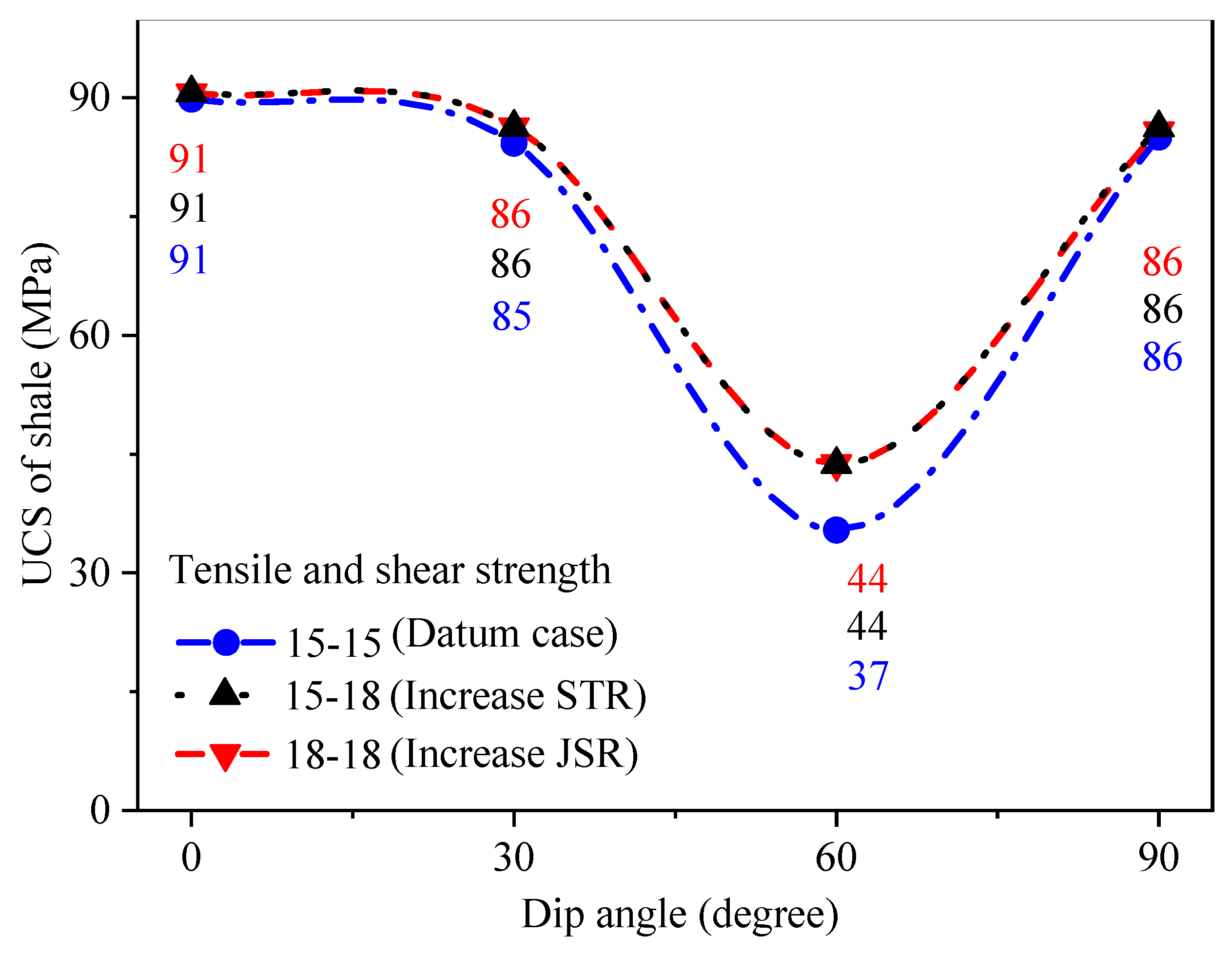
4.3. The Difference Between Bedding Strength and Its Shear-to-Tensile Strength Ratio

Both the variation of bedding strength and the shear-to-tensile strength ratio of beddings can change the UCS, crack type and complexity of the micro-cracking morphology in shale formation. However, the difference of their contributions has not been discussed. This section will comparatively analyze their effects and identify their difference using the indicators of JSR and STR. Both the JSR and the STR are taken as 1.0 for the datum case, where the tensile strength ( σ ¯ c s j ) and shear strength ( τ ¯ c s j ) of beddings are taken as 15 MPa, and other parameters are taken the same as those parameters in Table 1 and Table 2. Another two cases are used to compare their different influences between the JSR and STR. Increasing the tensile and shear strength of beddings simultaneously ( σ ¯ c s j = 18 MPa and τ ¯ c s j = 18 MPa) represents the influence of the JSR (JSR = 1.2). Increasing the shear strength of beddings only ( σ ¯ c s j = 15 MPa and τ ¯ c s j = 18 MPa) represents the influence of the STR (STR = 1.2).
The UCS at these bedding parameters is shown in Figure 15. When the JSR increases from 1.0 to 1.2, the UCS increases linearly at the dip angle of 60°. If the shear strength of the beddings is kept unchanged ( τ ¯ c s j = 18 MPa), the variation of the STR does not affect the UCS of the shale specimen. Therefore, the bedding strength contributes more greatly to the UCS of shale. The shear strength of beddings is the essential factor affecting the UCS, especially when the shear failure of beddings becomes the dominant fracture pattern.
Further, the percentages of matrix cracks and tensile cracks with different bedding strength parameters are presented in Figure 16a,b, respectively. Compared to the datum case in Figure 16a, both the increase of the JSR ( σ ¯ c s j = 18 MPa and τ ¯ c s j = 18 MPa) and STR ( σ ¯ c s j = 15 MPa and τ ¯ c s j = 18 MPa) can improve the percentage of the matrix cracks (Pbt+Pbs). The JSR induces a slightly higher percentage of matrix failure than the STR. In addition, increasing the JSR ( σ ¯ c s j = 18 MPa and τ ¯ c s j = 18 MPa) and STR ( σ ¯ c s j = 15 MPa and τ ¯ c s j = 18 MPa) can increase the percentage of tensile cracks (Pbt+Sjt) (see Figure 16b). For constant shear strength of beddings ( τ ¯ c s j = 18 MPa), a larger STR plays an even more significant role in the increase of tensile cracks in most circumstances. Generally, the increase of bedding strength has a greater impact on the increase of the percentage of matrix cracks, while the increase of shear-to-tensile strength ratio of beddings has a greater impact on the increase of percentage of tensile cracks.
The fractal dimensions of the final fracture morphology of shale formation with different bedding strength parameters are shown in Figure 17. Compared to the datum case, the effects of the JSR ( σ ¯ c s j = 18 MPa and τ ¯ c s j = 18 MPa) and STR ( σ ¯ c s j = 15 MPa and τ ¯ c s j = 18 MPa) on the crack fractal dimension has a close relationship with the dip angle of the bedding. When the dip angle is 0°, most of the micro-cracks occur in the rock matrix. Under this condition, the micro-cracking morphology becomes more complex with a higher STR. When the dip angle is 60°, most of the micro-cracks occur in the beddings. At this time, both the increase of the JSR ( σ ¯ c s j = 18 MPa and τ ¯ c s j = 18 MPa) and STR ( σ ¯ c s j = 15 MPa and τ ¯ c s j = 18 MPa) can improve the crack fractal dimension of the final fracture morphology to a similar extent. Table 3 summarizes the average of the fractal dimension for total cracks, matrix cracks and tensile cracks at different dip angles. These results clearly demonstrate that the shale beddings with a higher STR contribute more significantly to the complexity of micro-cracking morphology.

5. Conclusions

In this study, a numerical model is established for the uniaxial compression of laminated shale formation. Based on this model, the impacts of the bedding strength ratio (JSR) and shear-to-tensile strength ratio (STR) of beddings on the uniaxial compressive strength (UCS), the percentage of different crack types and the crack fractal dimension of the shale specimen have been investigated at different dip angles. Particularly, the percentage of each crack type, their transformation and the micro-cracking morphology are analyzed in detail. From these simulations and analyses, the following understandings and conclusions can be drawn.
First, the numerical model established in PFC2D can well simulate the stress-strain responses and crack growth process of shale under uniaxial compression loadings. It can successfully mimic four failure modes and their transformation in beddings and the matrix. Therefore, this numerical model can be used to simulate the mechanical characteristics and micro-cracking behaviors of layered rock materials.
Second, the bedding shear strength plays a decisive role in the UCS when the shear failure of bedding is dominant. Under this circumstance, the bedding shear strength is the essential index to change the UCS of shale. It is also found that the growth rate of UCS remains consistent with the increase in bedding strength.
Third, the dip angle plays a decisive role in the morphology of main fractures under uniaxial compression loadings, and bedding strength parameters can change the percentage of crack types and the complexity of sub-fractures in the shale formation. Therefore, the fracture morphology in shale formation depends on the local distribution of stress and strength.
Finally, micro-cracking morphology varies with the combination of tensile strength and shear strength of beddings. Their combination plays a different role in the percentage of matrix cracks and tensile cracks. A higher JSR can generate more matrix cracks. Comparatively, a higher STR may initiate more tensile cracks. The complexity of the micro-cracking morphology of shale may increase rapidly if the STR of beddings increases to some extent.

Author Contributions

Numerical simulation and writing, F.D. and J.W.; Editing, C.L. All authors have read and agreed to the published version of the manuscript.

Funding

National Natural Science Foundation of China (Grant No. 51674246).

Acknowledgments

The authors are grateful for the financial support from the National Natural Science Foundation of China (Grant No. 51674246).

Conflicts of Interest

The authors declare no conflict of interest.

References

  1. Cho, J.W.; Kim, H.; Jeon, S.; Min, K.B. Deformation and strength anisotropy of Asan gneiss, Boryeong shale, and Yeoncheon schist. Int. J. Rock Mech. Min. Sci. 2012, 50, 158–169. [Google Scholar] [CrossRef]
  2. Fjaer, E.; Nes, O.M. Strength anisotropy of Mancos shale. In Proceedings of the 47th US Rock Mechanics Symposium, San Francisco, CA, USA, 23–26 June 2013. [Google Scholar]
  3. Yang, X.X.; Jing, H.W.; Qiao, W.G. Numerical investigation of the failure mechanism of transversely isotropic rocks with a particle flow modeling method. Processes 2018, 6, 171. [Google Scholar] [CrossRef] [Green Version]
  4. Wei, J.; Niu, L.L.; Song, J.J.; Xie, L.M. Estimation of rock tensile and compressive moduli with Brazilian disc test. Geomech. Eng. 2019, 19, 353–360. [Google Scholar]
  5. Pietruszczak, S.; Mroz, Z. Formulation of anisotropic failure criteria incorporating a microstructure tensor. Comput. Geotech. 2000, 26, 105–112. [Google Scholar] [CrossRef]
  6. Pietruszczak, S.; Lydzba, D.; Shao, J.F. Modelling of inherent anisotropy in sedimentary rocks. Int. J. Solids Struct. 2002, 39, 637–648. [Google Scholar] [CrossRef]
  7. Lee, Y.K.; Pietruszczak, S. Application of critical plane approach to the prediction of strength anisotropy in transversely isotropic rock masses. Int. J. Rock Mech. Min. Sci. 2008, 45, 513–523. [Google Scholar] [CrossRef]
  8. Shi, X.C.; Yang, X.; Meng, Y.F.; Li, G. An anisotropic strength model for layered rocks considering planes of weakness. Rock Mech. Rock Eng. 2016, 49, 3783–3792. [Google Scholar] [CrossRef]
  9. Chong, Z.H.; Li, X.H.; Hou, P.; Wu, Y.C.; Zhang, J.; Chen, T.; Liang, S. Numerical investigation of bedding plane parameters of transversely isotropic shale. Rock Mech. and Rock Eng. 2017, 50, 1183–1204. [Google Scholar] [CrossRef]
  10. Khanlari, G.; Rafiei, B.; Abdilor, Y. Evaluation of strength anisotropy and failure modes of laminated sandstones. Arab. J. Geosci. 2015, 8, 3089–3102. [Google Scholar] [CrossRef]
  11. Chen, J.H.; Lan, H.X.; Macciotta, R.; Wu, Y.M.; Li, Q.W.; Zhao, X.X. Anisotropy rather than transverse isotropy in Longmaxi shale and the potential role of tectonic stress. Eng. Geol. 2018, 247, 38–47. [Google Scholar] [CrossRef]
  12. Liu, B.; Yang, Y.Q.; Li, J.T.; Chi, Y.A.; Li, J.H.; Fu, X.F. Stress sensitivity of tight reservoirs and its effect on oil saturation: A case study of Lower Cretaceous tight clastic reservoirs in the Hailar Basin, Northeast China. J. Pet. Sci. Eng. 2020, 184, 106484. [Google Scholar] [CrossRef]
  13. Guo, W.; Shen, W.J.; Li, X.Z.; Wang, N.; Liu, X.H.; Zhang, X.W.; Zhou, S.W. Study on mechanical characteristics and damage mechanism of the Longmaxi Formation shale in southern Sichuan Basin, China. Energy Explor. Exploit. 2020, 38, 454–472. [Google Scholar] [CrossRef]
  14. Liu, J.; Liang, X.; Xue, Y.; Fu, Y.; Yao, K.; Dou, F.K. Investigation on crack initiation and propagation in hydraulic fracturing of bedded shale by hybrid phase-field modeling. Theor. Appl. Fract. Mech. 2020, 108, 102651. [Google Scholar] [CrossRef]
  15. Meier, T.; Rybacki, E.; Backers, T.; Dresen, G. Influence of bedding angle on borehole stability: A laboratory investigation of transverse isotropic oil shale. Rock Mech. Rock Eng. 2015, 48, 1535–1546. [Google Scholar] [CrossRef]
  16. Li, A.; Shao, G.J.; Du, P.R.; Ding, S.Y.; Su, J.B. Numerical studies on stratified rock failure based on digital image processing technique at mesoscale. CMC-Comput. Mater. Contin. 2015, 45, 17–38. [Google Scholar]
  17. Li, H.R.; Dong, Z.K.; Ouyang, Z.L.; Liu, B.; Yuan, W.; Yin, H.W. Experimental investigation on the deformability, ultrasonic wave propagation, and acoustic emission of rock salt under triaxial compression. Appl. Sci. 2019, 9, 0635. [Google Scholar] [CrossRef] [Green Version]
  18. Liu, S.X.; Wang, Z.X.; Zhang, L.Y. Experimental study on the cracking process of layered shale using X-ray micro CT. Energy Explor. Exploit. 2018, 36, 297–313. [Google Scholar] [CrossRef] [Green Version]
  19. Wang, Y.; Feng, W.K.; Zhao, Z.H.; Zhang, D. Anisotropic energy and ultrasonic characteristics of black shale under triaxial deformation revealed utilizing real-time ultrasonic detection and post-test CT imaging. Geophys. J. Int. 2019, 219, 260–270. [Google Scholar] [CrossRef]
  20. Wang, J.G.; Liu, G.R. A point interpolation meshless method based on radial basis functions. Int. J. Numer. Methods Eng. 2002, 54, 1623–1648. [Google Scholar] [CrossRef]
  21. Zhang, Y.F.; Xia, X.Z.; Wu, Z.J.; Zhang, Q. The effect of initial defects on overall mechanical properties of concrete material. CMC-Comput. Mater. Contin. 2020, 62, 413–442. [Google Scholar]
  22. Cheng, H.; Zhou, X.P. New technique for frictional contact on crack slip in the extended Finite-Element Method framework. J. Eng. Mech. 2018, 144, 1–17. [Google Scholar] [CrossRef]
  23. Feng, F.; Li, X.B.; Rostami, J.; Peng, D.X.; Li, D.Y.; Du, K. Numerical investigation of hard rock strength and fracturing under polyaxial compression based on Mogi-Coulomb failure criterion. Int. J. Geomech. 2019, 19, 1–19. [Google Scholar] [CrossRef]
  24. Chen, X.; Yu, J.; Tang, C.A.; Li, H.; Wang, S.Y. Experimental and numerical investigation of permeability evolution with damage of sandstone under triaxial compression. Rock Mech. Rock Eng. 2017, 50, 1529–1549. [Google Scholar] [CrossRef]
  25. Zhang, X.X.; Wang, J.G.; Gao, F.; Wang, X.L. Numerical study of fracture network evolution during nitrogen fracturing processes in shale reservoirs. Energies 2018, 11, 2503. [Google Scholar] [CrossRef] [Green Version]
  26. Liu, C.; Xu, Q.; Shi, B.; Deng, S.; Zhu, H.H. Mechanical properties and energy conversion of 3D close-packed lattice model for brittle rocks. Comput. Geosci. 2017, 103, 12–20. [Google Scholar] [CrossRef]
  27. Zhou, J.; Lan, H.X.; Zhang, L.Q.; Yang, D.X.; Song, J.; Wang, S. Novel grain-based model for simulation of brittle failure of Alxa porphyritic granite. Eng. Geol. 2019, 251, 100–114. [Google Scholar] [CrossRef]
  28. Zhang, Y.J.; Liu, S.J.; Kou, M.M.; Wang, Z.Q. 3-D numerical study on progressive failure characteristics of marbles under unloading conditions. Appl. Sci. 2020, 10, 3875. [Google Scholar] [CrossRef]
  29. Ulusay, R. The complete ISRM suggested methods for rock characterization, testing and monitoring, 2007–2014; Springer International Publishing: Aarau, Switzerland, 2015. [Google Scholar]
  30. Yang, F.; Ning, Z.F.; Liu, H.Q. Fractal characteristics of shales from a shale gas reservoir in the Sichuan Basin, China. Fuel 2014, 115, 378–384. [Google Scholar] [CrossRef]
  31. Ross, D.J.K.; Bustin, R.M. The importance of shale composition and pore structure upon gas storage potential of shale gas reservoirs. Mar. Pet. Geol. 2009, 26, 916–927. [Google Scholar] [CrossRef]
  32. Dou, F.K.; Wang, J.G.; Zhang, X.X.; Wang, H.M. Effect of joint parameters on fracturing behavior of shale in notched three-point-bending test based on discrete element model. Eng. Fract. Mech. 2019, 205, 40–56. [Google Scholar] [CrossRef]
  33. Dou, F.K.; Wang, J.G.; Wang, H.M.; Hu, B.W.; Li, C.X. Discrete element analysis for hydraulic fracture propagations in laminated reservoirs with complex initial joint properties. Geofluids 2019, 2019, 3958583. [Google Scholar] [CrossRef]
  34. Mehranpour, M.H.; Kulatilake, P.H.S.W. Improvements for the smooth joint contact model of the particle flow code and its applications. Comput. Geotech. 2017, 87, 163–177. [Google Scholar] [CrossRef]
  35. Zhao, W.H.; Huang, R.Q.; Yan, M. Study on the deformation and failure modes of rock mass containing concentrated parallel joints with different spacing and number based on smooth joint model in PFC. Arab. J. Geosci. 2015, 8, 7887–7897. [Google Scholar] [CrossRef]
  36. Zhang, X.P.; Wong, L.N.Y. Loading rate effects on cracking behavior of flaw-contained specimens under uniaxial compression. Int. J. Fract. 2013, 180, 93–110. [Google Scholar] [CrossRef]
  37. Potyondy, D.O.; Cundall, P.A. A bonded-particle model for rock. Int. J. Rock Mech. and Min. Sci. 2004, 41, 1329–1364. [Google Scholar] [CrossRef]
  38. Pierce, M.; Ivars, D.M.; Potyondy, D.O.; Cundall, P.A. A synthetic rock mass model for jointed rock. Rock Mechanics: Meeting Society’s Challenges and Demands. In Proceedings of the 1st Canada-U.S. Rock Mechanics Symposium, Vancouver, BC, Canada, 27–31 May 2007. [Google Scholar]
  39. Wang, J.G.; Hu, B.W.; Wu, D.; Dou, F.K.; Wang, X.L. A multiscale fractal transport model with multilayer sorption and effective porosity effects. Transp. Porous Media 2019, 129, 25–51. [Google Scholar] [CrossRef]
  40. Shao, X.H.; Pang, X.Q.; Li, H.; Zhang, X. Fractal analysis of pore network in tight gas sandstones using NMR method: A case study from the Ordos Basin, China. Energy Fuels 2017, 31, 10358–10368. [Google Scholar] [CrossRef]
  41. Hu, B.W.; Wang, J.G.; Li, Z.Q.; Wang, H.M. Evolution of fractal dimensions and gas transport models during the gas recovery process from a fractured shale reservoir. Fractals 2019, 27, 1950129. [Google Scholar] [CrossRef]
  42. Zhou, M.Y.; Zhang, Y.F.; Zhou, R.Q.; Hao, J.; Yang, J.J. Mechanical property measurements and fracture propagation analysis of Longmaxi shale by micro-CT uniaxial compression. Energies 2018, 11, 1409. [Google Scholar] [CrossRef] [Green Version]
  43. Fan, X.Y.; Xu, F.L.; Chen, L.; Chen, Q.; Liu, Z.W.; Yao, G.H.; Nie, W. Dimension analysis-based model for prediction of shale compressive strength. Adv. Mater. Sci. Eng. 2016, 2016, 7948612. [Google Scholar] [CrossRef] [Green Version]
  44. Hu, W.R.; Kwok, C.; Duan, K.; Wang, T. Parametric study of the smooth-joint contact model on the mechanical behavior of jointed rock. Int. J. Numer. Anal. Methods Geomech. 2018, 42, 358–376. [Google Scholar] [CrossRef]
  45. Tian, W.L.; Yang, S.Q.; Wang, J.G.; Zeng, W. Numerical simulation of permeability evolution in granite after thermal treatment. Comput. Geotech. 2020, 126, 103705. [Google Scholar] [CrossRef]
  46. Wu, H.; Dai, B.; Zhao, G.Y.; Chen, Y.; Tian, Y.K. A novel method of calibrating micro-scale parameters of PFC model and experimental validation. Appl. Sci. 2020, 10, 3221. [Google Scholar] [CrossRef]
  47. Hou, P.; Gao, F.; Ju, Y.; Liang, X.; Zhang, Z.Z.; Cheng, H.M.; Gao, Y.N. Experimental investigation on the failure and acoustic emission characteristics of shale, sandstone and coal under gas fracturing. J. Nat. Gas Sci. Eng. 2016, 35, 211–223. [Google Scholar] [CrossRef]
Figure 1. A numerical model established for shale specimen in uniaxial compression loading.
Applsci 10 05496 g001
Figure 2. Force-displacement model for the interactions in rock matrix and beddings: (a) normal force versus normal displacement relationship; (b) tensile failure in matrix; (c) shear force versus shear displacement relationship; (d) shear failure in matrix (refer to Potyondy and Cundall [37]).
Applsci 10 05496 g002
Figure 3. Different particle motions in rock matrix and bedding-rock matrix interface: (a) particle moves around one another in matrix; (b) particle slips along beddings (modified from Dou et al. [32]).
Applsci 10 05496 g003
Figure 4. Laboratory testing on shale specimen: (a) testing machine and (b) shale specimens.
Applsci 10 05496 g004
Figure 5. Comparison of stress-strain curves obtained by experiments and simulations: (a) at 0° and (b) at 90°.
Applsci 10 05496 g005
Figure 6. Comparison of final fracture morphology observed in experiments and simulations. The first letter (a): dip angle = 0° and (b): dip angle = 90°; the second number 1: shale specimen, 2: in experiment; 3: in simulation.
Applsci 10 05496 g006
Figure 7. Stress-strain curves and evolution of micro-cracks simulated at different dip angles under uniaxial compression (joint strength ration (JSR) is 1.0; Sjs denotes shear crack of beddings; Sjt denotes tensile crack of beddings; Pbs denotes shear crack of matrix; Pbt denotes tensile crack of matrix). (a) dip angle = 0°; (b) dip angle = 30°; (c) dip angle = 60°; (d) dip angle = 90°
Applsci 10 05496 g007aApplsci 10 05496 g007b
Figure 8. Variations of uniaxial compressive strength with dip angle at different JSR.
Applsci 10 05496 g008
Figure 9. Effects of the JSR on the crack types in uniaxial compression (Sjs denotes shear crack of beddings; Sjt denotes tensile crack of beddings; Pbs denotes shear crack of matrix; Pbt denotes tensile crack of matrix). (a) JSR = 0.8; (b) JSR = 1.0; (c) JSR = 1.2; (d) comprehensive comparison of matrix cracks
Applsci 10 05496 g009
Figure 10. Distributions of crack type at different JSRs: (a) JSR = 0.8; (b) JSR = 1.0 (datum case); (c) JSR = 1.2.
Applsci 10 05496 g010aApplsci 10 05496 g010b
Figure 11. Stress-strain curves and evolution of micro-cracks simulated at different dip angles and in uniaxial compression (STR is 1.0). (a) dip angle = 0°; (b) dip angle = 30°; (c) dip angle = 60°; (d) dip angle = 90°
Applsci 10 05496 g011
Figure 12. Variation of uniaxial compressive strength of shale at different STR.
Applsci 10 05496 g012
Figure 13. Effects of shear-tensile strength ratio (STR) on the crack types in uniaxial compression. (a) STR = 0.8; (b) STR = 1.0; (c) STR = 1.2; (d) comprehensive comparison of matrix cracks
Applsci 10 05496 g013
Figure 14. Distributions of crack types at different STRs: (a) STR = 0.8; (b) STR = 1.0; (c) STR = 1.2.
Applsci 10 05496 g014
Figure 15. Variation of uniaxial compressive strength with dip angle at three bedding strength parameters.
Applsci 10 05496 g015
Figure 16. Variation of the percentage of crack types at three bedding parameters: (a) matrix cracks; (b) tensile cracks.
Applsci 10 05496 g016
Figure 17. Variation of crack fractal dimension with dip angle at three bedding strength parameters.
Applsci 10 05496 g017
Table 1. Micro-constitutive parameters calibrated for rock matrix.
Micro-ParameterValue
Particle density ρ (kg/m3)2330.0
Young’s modulus of particle E c (GPa)4.0
Young’s modulus of matrix E ¯ c (GPa)4.0
Moment contribution factor β 0.2
Ratio of normal to shear stiffness of particle k n / k s 1.8
Ratio of normal to shear stiffness of matrix k ¯ n p b / k ¯ s p b 1.8
Particle friction coefficient μ f 0.7
Tensile strength σ ¯ c p b (MPa)26.0
Shear strength τ ¯ c p b (MPa)32.5
Table 2. Micro-constitutive parameters calibrated for beddings.
Micro-ParameterValue
Normal stiffness k ¯ n s j (GPa/m)3000.0
Shear stiffness k ¯ s s j (GPa/m)2000.0
Tensile strength σ ¯ c s j (MPa)15.0
Shear strength τ ¯ c s j (MPa)18.0
Friction coefficient of beddings μ f 0.6
Dilation angle φ (degree)20.0
Table 3. Average of fractal dimension for different micro-cracking morphology in three cases.
TypeTotal CracksMatrix CracksTensile Cracks
Datum case σ ¯ c s j = 15 MPa τ ¯ c s j = 15 MPa1.3561.2191.242
Increase STR σ ¯ c s j = 15 MPa τ ¯ c s j = 18 MPa1.3831.2681.293
Increase JSR σ ¯ c s j = 18 MPa τ ¯ c s j = 18 MPa1.3661.2631.282

