Abstract
The threshing gap of the thresher device for rice combine harvester has to be adjusted in real time based on different feed rates to ensure the operation efficiency in the harvesting process. However, adjusting the threshing gap by changing the position of concave grid may result in unevenness of threshing gap of the thresher device and further impact on the fluidity of material in the thresher device; in addition, it is also unavailable to adjust the threshing gap by changing the drum diameter when the rice combine harvester is in operation. In view of the above and based on axial flow threshing drum, the design of a variable-diameter threshing drum available for overall and rapid drum diameter adjustment and the research on diameter adjustment device as well as electronic control self-locking device were introduced in this study. Besides, stress analysis was implemented to the diameter adjustment device to ensure the stability of the variable-diameter threshing drum. Field experiment was implemented to identify the difference between the impacts brought to the threshing performance (grain-entrainment loss rate, damage rate, threshing efficiency, and threshing power consumption) by both methods for threshing gap adjustment. The experiment result shows that the drum adjustment method with variable-diameter drum features higher grain-entrainment loss rate, threshing efficiency, and threshing power consumption, yet stable in terms of consumption fluctuation, but a lower damage rate than their counterparts with concave adjustment method.
1. Introduction
Rice, one of the major grain crops in China, is mostly harvested in a mechanized manner with combine harvester in the country [1]. The thresher device is classified into two types, i.e., tangential flow type and longitudinal axial flow type based on the confugration of the threshing drum. The tangential flow threshing device adopts the configuration with single or multiple drums arranged in the horizontal direction, which features simple structure and compactness; however, limited by the space in the horizontal direction, the threshing drum should not be too long and the threshing performance is far from perfect; while the longitudinal axial flow threshing device adopts the configuration with single or multiple drums arranged in the longitudinal direction, which lenghthens the drum (the area for threshing and separation) to gain relatively good threshing performance without widening the machine body; however, the grains suffer from repeated threshing processings, which leads to relatively high damage rate and power consumption. Most of the existing large-scale combine harvesters adopt the configuration with combination of the tangential flow drum and longitudinal axial flow drum, which utilize the tangential flow drum to separate the grains easy for being threshed and then achieve re-threshing separation of the material with the longitudinal axial flow drum, thus achieving relatively good threshing performance [2].
As a key component of the combine harvester, the performance of thresher device controls the operation performance, efficiency, and adaptability of the entire machine. The threshing gap refers to the clearance formed between the threshing element of the drum and the concave grid. As per the research, threshing gap plays an important role in the operation performance of the thresher device. The actual feed rate fluctuates greatly due to the different biomechanical characteristics and growth densities based on different varieties of rice during field harvesting. As the outcome, the performance of the combine harvester in terms of threshing and separation is decreased [3,4,5,6,7]. In that case, the adjustment of threshing gap according to different operation conditions on a timely basis should be implemented to make sure that the operation of the combine harvester is stable, thus improving the adaptability of the combine harvester in terms of harvesting [8,9].
Research in large quantities have been implemented by the researchers to investigate the method to change the threshing gap. There are two major adjustment methods, one of which is by means of changing the position of the concave grid. For example, hinging two ends of the concave grid with four mounting seats, placing the middle part of the concave grid on the cross beam, adjusting the cross beam by moving the connecting rod mechanism downwards or upwards, resulting in the consequent fall or rise of the middle part of the concave grid and increase or decrease of threshing gap; or hinge one end of the concave grid with the rack, and hinge the other end with the piston rod of the hydraulic cylinder, and achieve the adjustment of the clearance of the concave grid by means of expansion of the piston rod of the hydraulic cylinder. The adjustment mechanism for concave adjustment type is installed at the bottom or outside of the thresher device. While the combine harvester is in operation, the concave grid will be kept still and available for adjustment of the threshing gap by means of real-time changing of the concave grid position; the operation is simple and convenient [10,11,12]. Alternatively, the threshing drum adjustment type is available to adjust threshing gap by changing the diameter of the drum. The existing threshing drum, in most cases, has its threshing racks welded to several connecting bases which are then fixed onto the supporting wheel. Due to the fact that the drum keeps rotating during the operation of the combine harvester, the drum diameter can only be adjusted by stopping the combine harvester first. After that, open the threshing device from the side or the top and change the relative position between the connecting base at the end of each threshing rack of the drum and the supporting wheel one by one. In addition, the connecting bases at the end of each threshing rack and the supporting wheel should be adjusted and fixed at the same time. Apparently, this operation is not only complex but also time and labor consuming. Moreover, the drum diameter can only be adjusted to several fixed values and no stepless adjustment is available, which make it unsuitable for real-time adjustment during field operation [13,14]. Based on the comparison in terms of operation performance, concave plate type adjustment is used by most combine harvesters for changing threshing gap due to its simplicity for operation in the harvesting process [15].
The difference between the two adjustment methods lies not only in the way of operation but also in the effect, which is more obvious, on changing threshing gap. The concave plate type adjustment is only available to change the gap between the bottom of the concave grid and the drum instead of the threshing gaps on both sides of the drum. In addition, the moved concave grid is not concentric with the threshing drum, which may result in uneven threshing gaps within the thresher device. On the other hand, the drum type adjustment will only change the diameter of the drum and leave the positions of the drum and the concave grid unchanged; besides, the concave grid in the thresher device is still concentric with the drum, which results in even threshing gaps. Dainius has studied the impacts brought to the threshing performance for corn by Archimedes’ spiral type concave grid and circular arc concave grid in the tangential flow threshing device, respectively. The research shows that for relatively even threshing gap (Archimedes’ spiral type), the damage rate, and separation loss rate for corn are relatively low [16], however, no research is implemented on axial flow threshing drum. Sudajan et al. found that threshing drum adjustment type (even threshing gap) was available to effectively protect the thresher device from being blocked at the time of fluctuation of feed rate. The comparison in terms of threshing performance shows that the threshing drum adjustment type has a better prospect in application [17].
To solve the problem that the diameter of the threshing drum is difficult to adjust and real-time adjustment is unavailable during the operation of combine harvester, the research on the development of a variable-diameter threshing drum was described in this study. The variable-diameter threshing drum was available for convenient and rapid drum diameter adjustment during the operation of combine harvester by including diameter adjustment device and electronic control self-locking device in the existing threshing drum of combine harvester. In addition, an experiment was implemented to compare and analyze the differences in terms of impact brought to threshing performance by both adjustment types. The optimal way to prevent the thresher device from being blocked and improve the adaptability of harvesting by the combine harvester was explored.
2. Materials and Methods
2.1. Comparative Analysis of Both Adjustment Methods
Threshing drum adjustment type and concave adjustment type are shown in Figure 1a,b, respectively, and the resulted threshing gap cross sections are shown in Figure 1c,d, respectively. The initial gap between the threshing drum and the concave grid is 20 mm. For concave adjustment type, moving the concave grid upwards and downwards to increase the threshing gap to 30 mm or decrease it to 10 mm can only result in the change of the threshing gap between the bottom of the concave grid and the drum. However, the threshing gaps on both sides of the concave grid and that between the top cover and the drum will not change. As the result, the adjustment of threshing gap within the thresher device is not complete and the threshing gap is not even. In the case that the feed rate is too large, it is very difficult to ensure that no blockage will occur in the thresher device by increasing the threshing gap at the bottom of the concave grid only. In the case that the threshing gap has to be reduced due to the changes of the operation performance specifications of the threshing device, such as entrainment loss rate and the damage rate, it is very difficult to ensure the operation performance of the threshing device completely by decreasing the threshing gap at the bottom of the concave grid only. With the threshing drum adjustment type, in the case of increasing the threshing gap to 30 mm or decreasing it to 10 mm by changing the drum diameter, the threshing gap within the thresher device will change at the same time and the threshing gap is even. Therefore, when the feed rate is too large, increasing the threshing gap evenly may effectively prevent the thresher device from being blocked, while decreasing the threshing gap evenly may effectively ensure the operation performance of the thresher device as well.
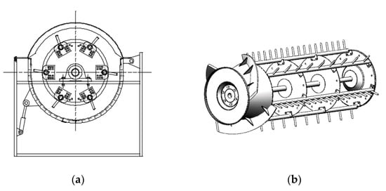
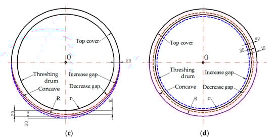
Figure 1.
Two threshing gap adjustment types: (a) Concave adjustment type; (b) Threshing drum adjustment type; (c) Cross section of concave adjustment type; (d) Cross section of threshing drum adjustment type.
To express the difference between the impacts brought to the threshing gap by both adjustment types accurately, the equations for the threshing gap cross section area with concave adjustment type and threshing drum adjustment type are as follows when the threshing gap is increased:
The difference between the two cross-sectional areas is therefore:
where S1 is the threshing gap cross-section area for the concave adjustment type and S2 is that for the threshing drum adjustment type (mm2), R is the concave grid radius (mm), r is the threshing drum radius (mm), and ΔL is the threshing gap variance (mm).
The equations for the threshing gap cross section area with concave adjustment type S1 and drum adjustment type S2 are as follows when the threshing gap is to be decreased:
The difference between the two cross-section areas is therefore:
For this combine harvester threshing experiment, the initial concave grid radius R = 320 mm, the initial threshing drum radius r = 300 mm, and the threshing gap variance ΔL = 10 mm, When the threshing gap was increased, the threshing gap cross-section area of the concave adjustment type S1 and threshing drum adjustment type S2 are 45,336 mm2 and 57,462 mm2, respectively, = 12,126 mm2, the threshing gap cross-section area of the threshing drum adjustment type was 26.7% larger than that of the concave adjustment type. When the threshing gap was decreased, the threshing gap cross-section area of the concave adjustment type S1 and threshing drum adjustment type S2 are 32,536 mm2 and 19,782 mm2, respectively = 12,754 mm2, the threshing gap cross-section area of the threshing drum adjustment type was 39.2% smaller than that of the concave adjustment type [18].
2.2. Design of Variable-Diameter Drum
2.2.1. Overall Structure of Variable-Diameter Drum
It can be concluded from the above analysis that the threshing drum adjustment type performs better than the concave adjustment type in terms of changing the threshing gap. However, the threshing drum adjustment type is more tedious in operation than the concave adjustment type, which makes it unavailable for real-time adjustment during the operation of combine harvester. Variable-diameter threshing drum is therefore designed to solve the problem that the threshing drum adjustment type is more tedious in operation and unavailable for real-time adjustment during the operation of combine harvester, thus to give full play to the advantages of threshing drum adjustment type. The design thought in which both the structural parameters and operating parameters are adjustable is adopted for the variable-diameter threshing drum [19]. In another word, the design includes the diameter adjustment device and the electronic control self-locking device into the traditional threshing drum. A pair of diameter adjustment devices connected with a sleeve in between is installed inside the front and rear supporting wheels of the drum and the electronic control self-locking device is installed at the rear part of the drum. For the overall structure, please refer to Figure 2.
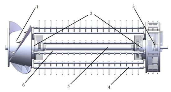
Figure 2.
3D diagram of variable-diameter threshing drum, 1. Feed wheel, 2. Diameter adjustment device, 3. Electronic control self-locking device, 4. Threshing rack, 5. Drum main shaft, 6. Sleeve.
2.2.2. Diameter Adjustment Device
It can be seen from Figure 1a that in the traditional drum diameter adjustment, the position of the connecting base at the end of each threshing rack should be changed one by one. Therefore, the operation is time and labor consuming. Several hole locations are provided at the end of each connecting base and adjustment in steps is available for drum diameter only. Overall and rapid changes of the relative positions between each threshing rack and the supporting wheel by diameter adjustment device is available, thus achieving the stepless adjustment of diameter. As the core parts of the diameter adjustment device, constant speed screw disc, and matching claws were designed according to Archimedes spiral principle. As shown in Figure 3a, the inner end face of the constant speed spiral plate is equipped with plane threads, the driving thread pitch of the threads is T = 8 mm, the spiral diameter is D = 150 mm. The thread teeth are embedded in one end plane of the six claws. The overall structure of the device is shown in Figure 3b, which consists of constant speed spiral plate, limit disc, claws, connecting rod, sun wheel, planet wheel, and spline sleeve. The constant speed spiral disc and sun wheel are jointly installed on the spline sleeve, the spline hub is installed on the drum shaft, and the limit disc is fixed on the support plates, where six claws are connected through each of the six I-shaped grooves, respectively. One end connected with the claw engages with the plane thread in the constant speed spiral disc, the other end is welded with the connecting rod, and the connecting rod is welded with the threshing tooth rod.
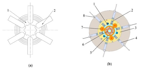
Figure 3.
Structure diagram of device for diameter adjustment, 1. Constant speed spiral disc, 2. Claw, 3. Limit disc, 4. Connecting rod, 5. Sun wheel, 6. Spline sleeve, 7. Planet wheel, 8. Threshing tooth rod: (a) Constant speed spiral disc and claws; (b) device for diameter adjustment.
Due to the complexity of the working conditions of threshing device in the combine harvester, in order to ensure the operation stability of variable-diameter threshing drum and prevent the radial displacement of claw caused by the force of threshing tooth rod and avoid the consequent rotation of constant speed spiral disc, force analysis was carried out for the constant speed spiral disc and claw in the device for diameter regulation.
The plane threads on the constant speed spiral disc are simplified to single-tooth plane threads for force analysis. The claw is taken as the research object. As shown in Figure 4a, it is assumed that the centrifugal force F acting on the claw is concentrated on the meshing points on the spiral, the counter force N is perpendicular to the tangent of the meshing points, and the inclination angle of the tangent line λ is the helix one. For further force analysis of meshing point, as shown in Figure 4b, when the claw moves downwards under centrifugal force, the friction Ff goes upwards. In the figure, R is the resultant force of normal reaction N and friction force Ff, Ft is the horizontal force component of R, friction angle ρ is the angle between R and N, and the angle between R and centrifugal force F is .
In the formula, Ft is the circumferential force driving the rotation of the constant speed spiral disc; F is the radial force driving the movement of the connecting claw; Thread lead angle λ = arctan, T: screw pitch of thread transmission, D: thread diameter; ρ is the friction angle of thread transmission, ρ = arctan f, and f is the friction coefficient.
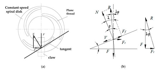
Figure 4.
Force analysis of plane threads and claws: (a) Force analysis of plane threads; (b) Force analysis of plane claws.
Formula (7) shows that if λ < ρ, then Ft is negative. As long as the condition λ < ρ is met, regardless of magnitude of the centrifugal force F, the claw will not move radially under its action, and self-locking can be formed. The lowest friction coefficient of steel is f = 0.05, and the lowest friction angle ρ is 3°. Additionally
The plane threads of constant speed spiral disc adopt pitch T = 8, diameter D = 150, T/D = 8/150 = 0.053, in full compliance with the self-locking condition of T/D < 0.16.
2.2.3. Electronic Control Self-Locking Device
Real-time adjustment of drum diameter during the operation of combine harvester is not available with the traditional method for drum diameter adjustment; in addition, timely adjustment based on different feed rate fluctuations and the changes of threshing performance specifications is not available as well. The electronic control self-locking device is installed at the rear part of the variable-diameter threshing drum, thus functioning for power input to diameter adjustment device and the stability of the diameter adjustment device. In addition, real-time adjustment of drum diameter based on different operation conditions is available.
As shown in Figure 5a, the electronic control self-locking device consists of two parts, i.e., the drive mechanism and the electronic control mechanism. The drive mechanism includes the first planetary gear set installed inside the rear supporting wheel and the second planetary gear set installed outside the supporting wheel. The sun wheel of the first planetary gear set is connected with the constant speed spiral disc in the diameter adjustment device through splined hub. While the sun wheel of the second planetary gear set is connected with the central gear in the electronic control mechanism through splined hub. Besides, three short shafts across the supporting wheel are used to connect the planetary gears in the two groups of planetary gear sets for linkage. As shown in Figure 5b, the electronic control mechanism consists of servo motor (DMKE, Guangzhou, China), motor gear, central gear, driver (DMKE, Guangzhou, China) and displacement sensor (MIRAN, Shenzhen, China). As the power output unit of the electronic control self-locking device, the motor gear is engaged with the central gear which is installed on the splined hub together with the sun wheel of the second planetary gear set. The function of self-locking is realized by the electronic control mechanism with the motor.
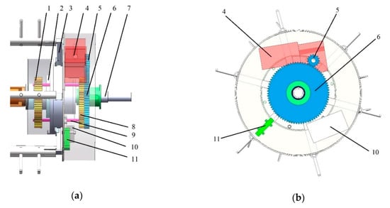
Figure 5.
Electronic control self-locking device, 1. The first planetary gear set, 2. Constant speed spiral disc, 3. Claw, 4. Motor, 5. Motor gear, 6. Central gear, 7. Main shaft, 8. The second planetary gear set, 9. Connecting shaft, 10. Driver, 11. Displacement sensor: (a) Side view of electronic control self-locking device; (b) Front view of electronic control self-locking device.
2.3. Comparative Experiment in Terms of Threshing Performance
To compare the threshing performance of both adjustment methods, the comparative experiment was implemented based on the feed rate and the threshing gap as the influence factors, and grain-entrainment loss rate, damage rate, threshing efficiency, and threshing power consumption as the performance specifications. In the field experiment, the forward speed of the combine harvester was used to control the feed rate based on the fixed cutting width and cutting table height [20]. The experiment, with its plan shown in Table 1, was implemented in two groups and five different forward speeds with the initial threshing gap set at 20 mm. In one group of the experiment, two adjustment methods were used to increase the threshing gap by 5 mm. The threshing gap with threshing drum adjustment type is 30 mm, while that with concave adjustment type is 20–30 mm. In the other group of the experiment, two adjustment methods were used to decrease the threshing gap. The threshing gap with threshing drum adjustment type is 10 mm, while that with concave adjustment type is 10–20 mm. Due to the fact that the threshing drum adjustment type and the concave adjustment type share the same threshing gap when the initial threshing gap is 20 mm. Only one group of experiment was implemented at the threshing gap of 20 mm. For all experiments, each group of experiment was repeated for three times and the average value was taken as the experiment result.

Table 1.
Experiment plan.
The experiment, as a field experiment, was implemented in Wujiang District, Suzhou City, Jiangsu Province with the combine harvester developed independently; the rice used in the experiment is “Jiahua” whose characteristics are partially shown in Table 2. As the basic model, YANMAR-AW82G (YANMAR, Osaka, Japan) was used as the combine harvester for the experiment with multiple devices and instruments installed, including in-line monitoring devices for grain impurity rate, damage rate and loss rate as well as the sensors for drum rotation speed and torque. The modified vehicle is also available for multiple control functions including the adjustment of cutting table height, position of the concave grid, the rotation speed of drum, the opening of lip sieve, forward speed, etc. Besides, real-time monitoring of operation parameters and performance parameters of the combine harvester is available as well [21,22,23,24].
Table 2.
Material characteristics of rice.
As shown in Figure 6, before the test, several fields with uniform rice growth were selected and tested. The harvesting length was 15 m in length for each test. The forward speed of the combine harvester was maintained within 0.6–1.6 m/s, to ensure the feeding rate. In the field test, the average cutting width is 2.58 m, the stubble height is 15 cm. After the material is separated by the threshing drum, the stalk is discharged from the grass discharge port and falls on the tarpaulin behind the combine harvester. After the test, the quality of stalks on the tarpaulin, the grain contained in the straw and the unpurified grain were collected by manual treatment to obtain the quantity of stalk, the rate of separation loss and the grain damage rate. The data obtained artificially were compared with those collected by the combine harvester by means of on-line monitoring to get the final degranulation performance data.
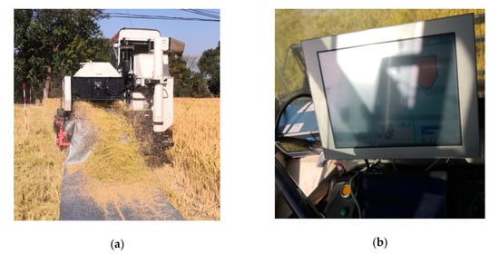
Figure 6.
Field experiment of combine harvester: (a) Mixture of the threshed output from the combine harvester fell off on the oil cloth to catch the material; (b) Monitoring system for threshing performance and threshing gap.
3. Results and Discussion
3.1. Overall Assembly and Operating Principle of Variable-Diameter Drum
The variable-diameter drum consists of three parts: feeding section, threshing and separation section, as well as electronic control self-locking section. One group of diameter adjustment devices were installed on the supporting wheel behind the feeding wheel and the other group of diameter adjustment devices were installed on the rear supporting wheel, as shown in Figure 7. The electric conduction link (MOFLON, Shenzhen, China) was installed at the end of the drum shaft, which was used to transfer current for the motor and transmit the signal generated by the displacement sensor to the processor outside the thresher device. The feeding wheel and the electronic control self-locking part were installed on both ends of the threshing and separation section, thus to form the complete variable-diameter drum in which the feeding wheel was connected with the electronic control self-locking device through the main shaft and six threshing rack. In addition, a pair of diameter adjustment devices were connected through the sleeve. Static balance test and dynamic balance test as well as counterbalance should be applied to the assembled variable-diameter drum, thus to ensure the dynamic balance stability of the variable-diameter drum.
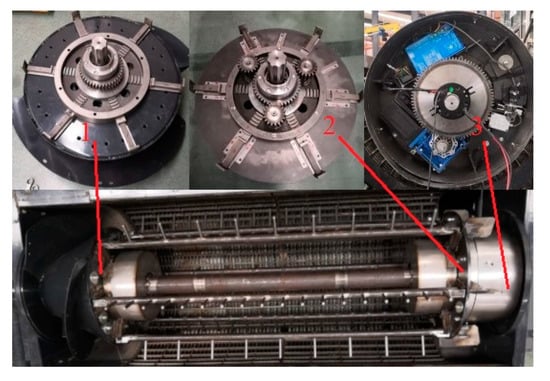
Figure 7.
Real product photo for the assembled variable-diameter threshing drum, 1. Feeding wheel and adjustment device 2. Adjustment device for rear supporting wheel 3. Electronic control self-locking device.
If the drum diameter has to be adjusted during the operation of the combine harvester, the gear of the controller driving motor will rotate and drive the central gear which further rotates the sun wheel and the planetary gear of the second planetary gear set through the splined hub. The second planetary gear set rotates the first planetary gear set of which the sun wheel rotates the constant speed spiral disc of the diameter adjustment device. The plane thread inside the constant speed spiral disc will rotate and initiate the radial reciprocating motion of the claw along the I shaped notch, thus to change the relative position of the threshing rack on the top of the claw. The two groups of diameter adjustment devices are connected with a sleeve for linkage, in this manner to realize the overall and rapid adjustment of the threshing drum diameter.
3.2. Grain-Entrainment Loss Rate
The grain entrainment loss refers to the free grain discharged together with the entrained stalks coming out of the straw outlet, which is one of the key specifications of the operation performance of the thresher device [25]. The comparison in terms of grain-entrainment loss rate under different forward speeds (feed rate) and threshing gaps with both adjustment methods is shown in Figure 8.
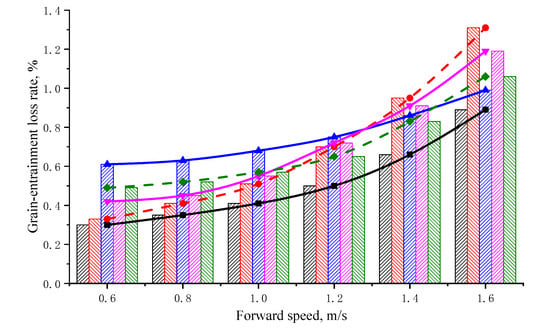
Figure 8.
Diagram for the variation of entrainment loss rate at different forward speeds under various threshing gaps, the black ▨ and -■- are initial gap of 20 mm, the red ▧ and -●- are threshing drum adjustment type of 10 mm, the blue ▨ and -▲- are concave adjustment type of 30 mm, the pink ▨ and -▼- are concave adjustment type of 10 mm, the green ▧ and -♦- are threshing drum adjustment type of 30 mm.
The forward speed of 0.6–0.8 m/s was defined as low speed and the corresponding feed rate was relatively low; the forward speed of 1–1.2 m/s was defined as medium speed and the corresponding feed rate was normal; the forward speed of 1.4–1.6 m/s was defined as high speed and the corresponding feed rate was large [26]. It can be seen from the bar graph that the grain-entrainment loss rates under all the five different threshing gaps increased with the rising of the forward speed. Under low speed, the entrainment loss rates listed in ascending order are: initial gap of 20 mm, threshing drum adjustment type of 10 mm, concave adjustment type of 10 mm, threshing drum adjustment type of 30 mm, and concave adjustment type of 30 mm. Under medium speed, with the increase of forward speed, the entrainment loss rate with concave adjustment type of 30 mm remained the highest. The entrainment loss rate with threshing drum adjustment type with 10 mm and that with concave adjustment type of 10 mm exceeded the entrainment loss rate with threshing drum adjustment type of 30 mm. The entrainment loss rate with initial gap of 20 mm remained the lowest. Under high speed, the entrainment loss rate with threshing drum adjustment type of 10 mm was the highest, while the entrainment loss rate with concave adjustment type of 10 mm was in the second place. The entrainment loss rate with threshing drum adjustment type of 30 mm exceeds that with concave adjustment type of 30 mm and took the third place. The entrainment loss rate with initial gap of 20 mm was the lowest. The entrainment loss rate decreased at first and then increased with the increase of the threshing gap. This is because that with the increase of the threshing gap, the thickness of grain layer is thinned, and grain has increased possibilities to penetrate the grain layer. Therefore, the entrainment loss rate is becoming smaller gradually; while when the threshing gap is too large, the condition goes against the separation of grains, therefore the entrainment loss rate will go higher.
It can be seen from the curve diagram that with the increase of forward speed, the entrainment loss rate with initial gap of 20 mm was the lowest all the time. However, the amplification trend of the entrainment loss rate under high speed was higher. The impact brought to the entrainment loss rate with threshing drum adjustment type of 30 mm featuring relatively higher threshing gap by the forward speed was not obvious. On the other hand, the impact to entrainment loss rate of the threshing drum adjustment type of 10 mm featuring the lowest threshing gap was the most obvious. Under low speed, the entrainment loss rate with threshing drum adjustment type of 10 mm was in second place and that with concave adjustment type of 10 mm took third place. However, with the increase of the forward speed, the amplification trend of entrainment loss rate with threshing drum adjustment type of 10 mm was higher than that with concave adjustment type of 10 mm. In addition, in the section from 1.2–1.4 m/s, the entrainment loss rate with threshing drum adjustment type of 10 mm became the highest by exceeding that with concave adjustment type of 10 mm. This is because within the thresher device, the threshing gap with concave adjustment type of 10 mm is larger than that with threshing drum adjustment type of 10 mm. When the forward speed is relatively low and the feed rate is relatively small, the smaller threshing gap makes the grain separation ability stronger. At this time, the entrainment loss rate with threshing drum adjustment type of 10 mm is lower than that with concave adjustment type of 10 mm. However, with the increase of feed rate, the thickness of the grain layer within the thresher device increases, and the possibility for the threshed grains to penetrate the grain layer becomes lower, which results the gradual increase of entrainment loss rate. Therefore, it eventually leads to the phenomenon that the entrainment loss rate with threshing drum adjustment type of 10 mm has a higher amplification and then exceeds that with concave adjustment type of 10 mm.
Under low speed, the entrainment loss rate with threshing drum adjustment type of 30 mm was higher than that with concave adjustment type of 30 mm. With the increase of forward speed, both amplification trends were relatively low. When the forward speed was too large, the amplification of the entrainment loss rate with concave adjustment type of 30 mm became larger and exceeds the entrainment loss rate with threshing drum adjustment type of 30 mm within the section from 1.4 to 1.6 m/s. This is because that within the thresher device, the threshing gap with threshing drum adjustment type of 30 mm is higher than that with concave adjustment type of 30 mm. Although the feed rate is relatively low, the overall threshing gap within the thresher device is relatively large, and the relatively smaller threshing spaces on both sides of the drum with concave adjustment type of 30 mm make the separation ability of the grain stronger. Therefore, the entrainment loss rate is lower than that with threshing drum adjustment type of 30 mm. However, with the increase of feed rate, the thickness of the grain layer become larger, relatively speaking, the grain layer with concave adjustment type of 30 mm is thicker, and the possibility for the threshed grain to penetrate the grain layer decreases, which results in the great increase of its entrainment loss rate. Dainius et al. has studied the loss rate of grain under different gaps and rotation speeds. They found that when the threshing gap is too small, the entrainment loss rate increase with the increase of the rotation speed of the drum. When the threshing gap was increased, the entrainment loss rate would decrease with the increase of the rotation speed of the drum. However, when the rotation of the drum was relatively low, the entrainment loss rate would increase gradually with the increase of threshing gap. When the rotation speed was increased, the entrainment loss rate would decrease gradually with the increase of threshing gap [16]. It can be interpreted that with the increase of the rotation speed of the drum, the centrifugal force of the material within the thresher device will increase, and the thickness of the material layer will become smaller. This is beneficial for grain separation; therefore, the entrainment loss rate will become smaller gradually.
3.3. Grain Damage Rate and Threshing Efficiency
The study shows that excessive threshing may result in lower threshing loss but higher grain loss; provided the threshing efficiency is guaranteed, decreasing the collision of grains and the frequency for being hit will decrease the damage rate of the grains greatly [27,28].
It can be seen from Figure 9 that with five different threshing gaps, with the increase of forward speed and feed rate, the grain damage rate would increase gradually. The damage rate with concave adjustment type of 30 mm was the lowest and that with concave adjustment type of 30 mm took second place. Besides, the rising trends in both cases are relatively stable. The damage rate with initial gap of 20 mm was on the medium level, and that with threshing drum adjustment type of 10 mm was the highest, which was higher than the damage rate with concave adjustment type of 10 mm. Too small a threshing gap may result in the sharp increase of damage rate in both cases when the forward speed is within the range of 1.2–1.4 m/s. With the increase of forward speed, the threshing efficiency would decrease gradually. The threshing efficiency with threshing drum adjustment type of 30 mm was the lowest and that with concave adjustment type of 30 mm took second place. Besides, the decreasing trends in both cases were relatively stable. The threshing efficiency with an initial gap of 20 mm was on the medium level, and that with threshing drum adjustment type of 10 mm was the highest. The threshing efficiency with concave adjustment type of 10 mm took second place. Small threshing gap may result in the sharp decrease of threshing efficiency in both cases when the forward speed is within the range of 1.2–1.4 m/s. It can be seen from the curve growth trend of Figure 8 and Figure 9 that when the speed is between 0.8-1.0m/s, the increase in entrainment loss rate and damage rate are lower, the threshing efficiency is higher, and the harvest efficiency is the best at this time.
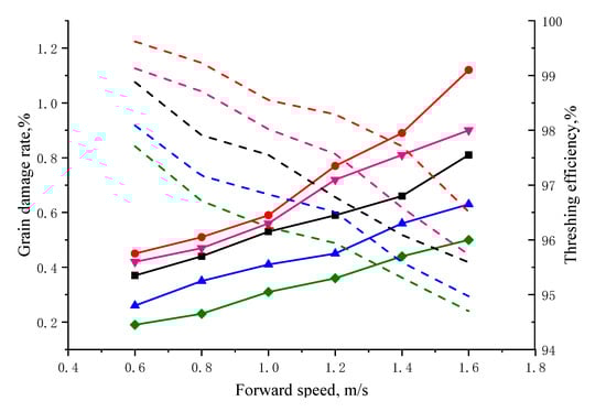
Figure 9.
Diagram for the variation of grain damage rate and threshing efficiency at different forward speeds under various threshing gaps, the black --- and -■- are initial gap of 20 mm, the red --- and -●- are threshing drum adjustment type of 10 mm, the blue --- and -▲- are concave adjustment type of 30 mm, the pink --- and -▼- are concave adjustment type of 10 mm, the green --- and -♦- are threshing drum adjustment type of 30 mm.
Among all the five threshing gaps, the one with threshing drum adjustment type of 30 mm was larger than that with concave adjustment type of 30 mm. The threshing gap with threshing drum adjustment type of 10 mm was smaller than that with concave adjustment type of 10 mm. With the decrease of threshing gap, the grain would suffer increasingly stronger friction and squeezing, therefore the damage rate of grain would increase, and the threshing efficiency would be higher gradually. With the increase of forward speed, the feed rate would increase and the thickness of the material layer within the thresher device would be higher. The quantity of the material was high, and the threshing efficiency of the grain would decrease gradually. In addition, the impact, friction, brushing, and squeezing to the grain became stronger, which would lead to increasingly higher grain damage rate. When the threshing gap was increased, the grain damage rate with threshing drum adjustment type was lower than that with concave adjustment type. In the meantime, the threshing efficiency with threshing drum adjustment type was lower than that with concave adjustment type, but the difference was not big. When the threshing gap was decreased, the grain damage rate with threshing drum adjustment type was higher than that with concave adjustment type. In addition, the difference was relatively small under low or medium feed rate. However, the threshing efficiency with threshing drum adjustment type was far higher than that with concave adjustment type. This result is similar to the conclusion drawn from Xu’s study, that is, with the increase of feed rate, the damage rate will be higher. In the meantime, the threshing efficiency will be lower with the increase of feed rate [29].
3.4. Power Consumption of Thresher Device
Some studies have shown that the threshing power consumption is subject to both the changes of feed rate and the type of threshing drum [30,31]. To differentiate the impacts to threshing power consumption brought by both adjustment methods for threshing gap, traditional threshing drum was adopted in concave adjustment type while variable-diameter drum was adopted in threshing drum adjustment type. Under the forward speed of 1 m/s, analysis was implemented on the results of power consumption obtained from the experiments with both adjustment methods in two cases, i.e., the threshing gap was increased by 10 mm (30 mm) and decreased by 10 mm (10 mm), respectively.
As shown in Figure 10a, when the threshing gap was increased to 30 mm, the threshing power consumption with concave adjustment type features rather high fluctuation range upwards and downwards, in which the maximum power consumption was 48.31 KW and the average power consumption was 28.73 KW. In addition, the instant threshing power consumption was not stable, and the curve was not regular. The curve for threshing power consumption with threshing drum adjustment type has an outline in the form of trapezoid with relatively stable curve fluctuation. The maximum power consumption was 54.15 KW and the average power consumption was 34.83 KW. As shown in Figure 10b, when the threshing gap was decreased to 10 mm, the maximum power consumption with concave adjustment type was 51.71 KW and the average power consumption was 30.22 KW. The maximum power consumption with threshing drum adjustment type was 59.53 KW and the average power consumption was 36.21 KW. The fluctuation ranges of threshing power consumption curve for both concave adjustment type and threshing drum adjustment type were relatively large, while the curve fluctuation with threshing drum adjustment type was relatively stable. This is because the decrease of threshing is relatively small at this moment and blockage may occur to the drum. On the other hand, the decrease of threshing with threshing drum adjustment type is even, therefore the fluctuation of power consumption curve is more stable and the shape is more regular, similar to a trapezoid.
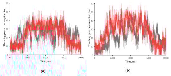
Figure 10.
Diagram for the comparison in terms of threshing power consumption between both adjustment methods at the forward speed of 1 m/s, the red line is threshing drum adjustment type, the black line is concave adjustment type: (a) Threshing drum adjustment type and concave adjustment type with the threshing gap of 30 mm; (b) Threshing drum adjustment type and concave adjustment type with the threshing gap of 10 mm.
In general, the fluctuation of threshing power consumption curve with concave adjustment type was relatively large and the curve was not regular. In the meantime, the fluctuation of threshing power consumption curve with threshing drum adjustment type was stable and the outline of the curve was in the shape of a trapezoid. This is because that with the concave adjustment type, the threshing gap within the thresher device is not even and the material conveying capacity of the thresher device is relatively poor. The threshing power consumption with concave adjustment type was smaller than that with threshing drum adjustment type. This is because that the concave adjustment type adopts traditional threshing drum which is relatively lighter. However, the threshing drum adjustment type adopts the variable-diameter drum which is heavier and results in higher power consumption. Threshing power consumption is related to the threshing gap and the quality of the threshing drum, lightweight treatment should be considered in the successive studies, thus to decrease the weight of the drum.
4. Conclusions
In this study, analysis was implemented in detail on the advantages and disadvantages of both existing adjustment methods for threshing gap, i.e., concave adjustment type and threshing drum adjustment type. On the basis of the advantages and disadvantages, a variable-diameter threshing drum was designed and further used to design, based on the theory of Archimedes’ spiral, a diameter adjustment device. The device was equipped with an electronic control self-locking device at the rear part of the drum and available for real-time adjustment of the drum diameter during the operation of the combine harvester, thus solving the difficulties encountered in the operation of threshing drum adjustment type, unavailability of real-time adjustment, etc.
Comparative analysis through field experiment was implemented to identify the impacts brought to the grain-entrainment loss rate, damage rate, threshing efficiency, and threshing power consumption by both methods for adjustment. When the threshing gap is to be increased, the cross-section area of the threshing gap with threshing drum adjustment type is higher than that with concave adjustment type by 26.7%. While, if the threshing gap is to be decreased, the cross-section area of the threshing gap with threshing drum adjustment type is lower than that with concave adjustment type by 39.2%. As per the experiment results, under low and medium forward speeds (0.6–1.2 m/s), the grain-entrainment loss rate with threshing drum adjustment type is lower than that with concave adjustment type, i.e., lower than 0.8% in both cases; while the grain-entrainment loss rate with threshing drum adjustment type is higher than that with concave adjustment type under high speed (1.4–1.6 m/s). When the threshing gap is increased to 30 mm, the grain damage rate and the threshing efficiency with threshing drum adjustment type is lower than that with concave adjustment type. On the other hand, the concave adjustment type features relative large fluctuation amplitude of threshing power consumption, instable instantaneous threshing power consumption and irregular curve; while the threshing drum adjustment type features the threshing power consumption curve outlined in trapezoid, relatively stable curve fluctuation but higher average power consumption than that with concave adjustment type by 6.1 KW. When the threshing gap is decreased to 10 mm, the threshing drum adjustment type features higher grain damage rate than that with concave adjustment type, while the difference is small at low and medium speeds (0.6–1.2 m/s), but with far higher threshing efficiency in the meantime. Both the concave adjustment type and the threshing drum adjustment type feature relatively large fluctuation amplitude in terms of threshing power consumption; however, the fluctuation of the curve with threshing drum adjustment type is relatively stable and the average power consumption is higher than that with the concave adjustment type by 5.99 KW.
The designed variable-diameter threshing drum was proven to have excellent threshing performance and stable operation efficiency. Based on this, successive studies should focus on how to decrease the mass of the variable-diameter drum, threshing power consumption, etc., as well as how to achieve to the self-adaptive control of variable-diameter drum during the harvesting process, thus improving the threshing performance and harvesting adaptability of the combine harvester effectively.
Author Contributions
Conceptualization, Z.S.; methodology, Z.S.; software, Z.S.; validation, Z.S. and Y.L. (Yu Li); formal analysis, Z.S.; investigation, Z.S.; resources, Z.S.; data curation, Z.S. and Y.L. (Yu Li); writing—original draft preparation, Z.S.; writing—review and editing, Y.L. (Yaoming Li) and Z.L.; visualization, Y.L. (Yaoming Li); supervision, Y.L. (Yaoming Li); project administration, Y.L. (Yaoming Li); funding acquisition, Y.L. (Yaoming Li). All authors have read and agreed to the published version of the manuscript.
Funding
This research was jointly supported by National Natural Science Foundation of China (51975257), National Natural Science Foundation of China (51905221), Jiangsu Research and Practice Innovation Program Project (KYCX20_3086).
Conflicts of Interest
The authors declare no conflict of interest.
References
- Yuan, L.P. Progress in super-hybrid rice breeding. Crop. J. 2017, 5, 100–102. [Google Scholar] [CrossRef]
- Liang, Z.W.; Li, Y.M.; Baerdemaeker, J.; Xu, L.Z. Development and testing of a multi-duct cleaning device for tangential- longitudinal flow rice combine harvesters. Biosyst. Eng. 2019, 182, 95–106. [Google Scholar] [CrossRef]
- Kawamura, N.; Hisashi, H. A basic study on harvesting of standing grain. J. Soc. Agr. Mach. 1971, 33, 156–162. [Google Scholar]
- Toshikazu, M.; Tatsuro, S. The evaluation of harvest loss occurring in the ripening period using a combine harvester in a shattering-resistant line of common buckwheat. Japanese J. Crop. Sci. 2017, 86, 62–69. [Google Scholar]
- Singh, K.N.; Singh, B. Effect of crop and machine parameters on threshing effectiveness and seed quality of soybean. J. Agric. Eng. Res. 1981, 17, 23–28. [Google Scholar] [CrossRef]
- Dosa, A. Mechanization of peanut harvesting in Malaysia. Agric. Mech. Asia, Afr. Lat. Am. 1984, 15, 44–48. [Google Scholar]
- Alizadeh, M.R.; Bagheri, I. Field performance evaluation of different rice threshing methods. Int. J. Nat. Eng. Sci. 2009, 3, 139–143. [Google Scholar]
- Osueke, C.O. Simulation and optimization modelingof performance of a cereal thresher. Int. J. Eng. Technol. IJET-IJENS. 2011, 11, 143–152. [Google Scholar]
- Miu, P.I.; Kutzbach, H.D. Modeling and simulation of grain threshing and separation in threshing units-Part I. Comput. Electron. Agric. 2007, 60, 96–104. [Google Scholar] [CrossRef]
- Regier, B.D.; Matousek, A.R.; Kelvin, E.K. Combine harvester processing system having adjustable concaves on a suspension system. U.S. Patent 8,133,100, 13 March 2012. [Google Scholar]
- Bergkamp, A.R.; Regier, B.D. Constant pressure concave assembly in a combine harvester processing system. U.S. Patent 9,220,200, 29 December 2015. [Google Scholar]
- Matousek, R.A.; Claerhout, B.S.; Secrest, R.S. Three section threshing concave configuration and adjustment mechanism for an agricultural harvesting combine. U.S. Patent 0,716,259, 21 July 2020. [Google Scholar]
- GIvan, V.N.; Vla, D. Kinematic study of threshing process conducted by tangential threshing system of conventional cereal harvesting combines. INMATEH-Agric. Eng. 2014, 44, 59–68. [Google Scholar]
- Tang, Z.; Li, Y.M. Modeling and design of a combined transverse and axial flow threshing unit for rice harvesters. Span. J. Agric. Res. 2014, 12, 973–983. [Google Scholar] [CrossRef]
- Pahoni, C. Research regarding the performances obtained by the 560 and the 750 Claas Lexion combines in maize grain harvesting. Sci. Pap. 2012, 69, 331–333. [Google Scholar]
- Steponavičius, D.; Pužauskas, E.; Špokas, L.; Jotautienė, E.; Kemzūraitė, A.; Petkevičius, S. Concave design for high-moisture corn ear threshing. Mechanika 2018, 24, 80–91. [Google Scholar] [CrossRef]
- Sudajan, S.; Salokhe, V.M.; Triratanasirichai, K. PM—power and machinery: Effect of type of drum, drum speed and feed rate on sunflower threshing. Biosyst. Eng. 2002, 83, 413–421. [Google Scholar] [CrossRef]
- Su, Z.; Li, Y.M.; D, Y.H.; Tang, Z.; Liang, Z.W. Simulation of rice threshing performance with concentric and non-concentric threshing gaps. Biosyst. Eng. 2020, 197, 270–284. [Google Scholar] [CrossRef]
- Kang, J.; Yuan, Y.; Liu, H. Load control of threshing cylinder of small-sized harvester based on current detection. Eng. Agric. 2017, 150–156. [Google Scholar] [CrossRef]
- Meusel, C.; Kieu, D. Evaluating operator harvest technology within a high-fidelity combine simulator. Comput. Electron. Agric. 2018, 148, 309–321. [Google Scholar] [CrossRef]
- Chen, J.; Lian, Y.; Li, Y.M. Design of sampling device for rice grain impurity sensor in grain-bin of combine harvester. Chin. Soc. Agric. Mach. 2019, 35, 18–25. [Google Scholar]
- Chen, J.; Gu, Y.; Lian, Y. Online recognition method of impurities and broken paddy grains based on machine. Chin. Soc. Agric. Mach. 2018, 34, 187–194. [Google Scholar]
- Liang, Z.W.; Li, Y.M.; Xu, L.Z. Sensor for monitoring rice grain sieve losses in combine harvesters. Biosyst. Eng. 2016, 147, 51–56. [Google Scholar] [CrossRef]
- Chen, J.; Lian, Y.; Li, Y.M. Real-time grain impurity sensing for rice combine harvesters using image processing and decision-tree algorithm. Comput. Electron. Agric. 2020, 175, 105591. [Google Scholar] [CrossRef]
- Mao, H.; Wang, Q.; Li, Q. Modelling and simulation of the straw-grain separation process based on a discrete element model with flexible hollow cylindrical bonds. Comput. Electron. Agric. 2020, 170, 105229. [Google Scholar] [CrossRef]
- Chen, J.; Ning, X.; Li, Y.M.; Yang, G. A fuzzy control strategy for the forward speed of a combine harvester based on KDD. Appl. Eng. Agric. 2017, 33, 15–22. [Google Scholar]
- Mahmoud, A.R.; Buchele, W.F. Corn Ear Orientation effects on mechanical damage and forces on concave. Trans. Asae. 1975, 18, 0444–0447. [Google Scholar] [CrossRef][Green Version]
- Ferreira, V.F.; Oliveira, J.A.; Ferreira, T.F. Quality of maize seeds harvested and husked at high moisture levels. J. Seed Sci. 2013, 35, 276–283. [Google Scholar] [CrossRef][Green Version]
- Xu, B.Y.; Ni, X.D.; Wang, Y. Optimization of threshing quality control strategy based on Type-2 fuzzy logic controller. ELEKTRONIKA IR ELEKTROTECHNIKA 2020, 2, 26. [Google Scholar]
- Tang, Z.; Li, Y.M. Experiments on variable-mass threshing of rice in the tangential-longitudinal-flow combine harvester. J. Agric. Sci. Technol. 2013, 15, 1319–1334. [Google Scholar]
- Sessiz, A.; Koyuncu, T.; Pinar, Y. Soybean threshing efficiency and power consumption for different concave materials. Agric. Mech. Asia, Afr. Lat. Am. 2007, 38, 56–59. [Google Scholar]
© 2020 by the authors. Licensee MDPI, Basel, Switzerland. This article is an open access article distributed under the terms and conditions of the Creative Commons Attribution (CC BY) license (http://creativecommons.org/licenses/by/4.0/).