Abstract
Changing market requirements, pressure to minimize production costs, competition, but also legislative restrictions have an impact on a number of areas, not excluding the automotive industry. Currently, development trends are moving towards the application of advanced technological solutions and materials, with the aim to reduce vehicle‘s weight, increase their strength and safety, and at the same time reduce the emission of vehicles. The Shell Eco Marathon competition is an excellent platform for the implementation of these activities. The main goal of the competition is to support the creative invention of research teams and bring innovative ideas and technical solutions. The scientific article focuses on a detailed analysis of development steps in the construction of experimental vehicles. The results of the research were presented at a competition in London 2019 with successful achievement. This work is a contribution to the design and aerodynamic optimization of the body and at the same time brings new ideas and structural elements to improve the production power unit.
1. Introduction
The global crisis, which culminated in 2008 and 2009, resulted in a decline in key markets, while the automobile factories subsequently had to significantly streamline their production and get rid of often interesting but marginal models. Demand fell, which meant for developers that they had to come up with better cars that could convince customers. Although downsizing came, quite paradoxically, smaller and more powerful engines got into smaller cars, as well as much richer equipment that the consumer was previously accustomed to in premium cars. Simply put, the fight for the customer began. It was this change that helped the car industry revive quickly after the crisis. At the same time, however, regulations related to a more sensitive perception of the environment have begun to enter the realm of cars, and increasing emphasis has begun to be placed on ecology [,].
In order to gain a market-leading position, motor vehicle manufacturers are trying to present vehicles that are timeless not only in terms of the materials used but also the technology of their production. These efforts are supported by various global projects that also give young people the opportunity to present their plans with a single goal, to engage and gain demand. One such activity is the Shell Eco Marathon international competition, which actively encourages young people to participate in the development and production of experimental cars using new materials and alternative propulsions []. The first races in this competition (1985–1999) took place on the Paul Richard circuit in France. In 2009, the race left this country for the first time and took place in Germany, then in 2015 in the Netherlands, and since 2016, this competition has been held in England.
The Slovak Republic, represented by the Faculty of Mechanical Engineering TUKE, has been participating in this competition since 1994, when the B&S 1 car model was introduced for the first time, with dual-circuit mechanical brakes on the rear wheel []. Since then, the development but also the production of the car made for this competition has undergone several changes, while the production and characteristics of the latter (the eighth in order) are described in this article.
1.1. Innovations in Car Manufacture
The first car, Benz’s tricycle, was an open tricycle with a light vehicle design. Its three-wheeled chassis and frame were made of bent and welded steel tubes. The engine had to be part of the frame. The wheels were only wire, the rear then had tin bushings. The seat was made of wood and, together with the backrests, was covered with leather for the comfort of the passengers. The belt brake was also made of leather. Over time, along with the development of the car, its body changed mainly [,,].
The automotive industry has undergone extreme innovations over the last few years, where it is possible to monitor the use of various elements as well as types of materials that are the result of changes in market requirements. Materials used today must meet several criteria before they can be approved for use [,]. Some of these criteria are the result of legislation and regulations in relation to the environment and safety, others fall according to the requirements of the customers themselves []. One of the requirements of the market is also to increase the vehicle’s performance, which results in the development and production of more efficient engines, more aerodynamic vehicle shapes, but also a reduction in its weight. There is constant pressure to use engines that use less fuel and produce fewer emissions. In addition, the reduction of the material used leads to the conservation of natural resources. There are also changes in the materials from which the car is made. Today, more than half of the total production volume of a modern car consists of cast iron and steel (55%), about 11%—plastic, about 9%—aluminum alloys, 7%—rubber and glass, 3%—non-ferrous alloys (magnesium, titanium, copper) and 1%—other materials (varnishes, paints, electric wires, cladding materials, etc.) [,,].
One of the important processes in the use and production of components for the automotive industry is the use of digitization, especially 3D scanners, which have found their wide-ranging application in the automotive environment. Digitization has become an integral part of the development and assembly process in the automotive industry. Its implementation and operation significantly reduce the time required to design or inspect components []. With 3D scanning, small components as well as large parts can be scanned. The reason is the fact that very complex curves are often used here, the modeling of which is extremely difficult or impossible. This method of digitization can also be referred to as development digitization, as it is implemented in the design or development process of the vehicle or its components [,]. The actual choice of 3D scanner and scanning technology largely depends on what is being scanned. Of the wide range of these devices, some are ideal for scanning closer objects, such as short-range scanners, and others for scanning more distant points, where medium or long-range scanners are more appropriate []. There are several different 3D scanning methods designed to obtain the dimensions, color composition, and geometric parameters of spatial objects in order to create a 3D model or to store information about the scanned object in digital form. Basically, there is no 3D scanning method that would be “the best”, it is always necessary to adapt the choice of 3D scanner and scanning methodology to the scanned object to provide a unique solution to the problem in different cases [].
1.2. Characteristics of the Shell Eco Marathon Competition
The role of the Shell Eco Marathón international competition is to support the invention and design skills of participants, increase interest in technology, introduce new technologies and materials in vehicle and engine construction and, last but not least, deepen participants ‘overall knowledge of technology and improve participants’ language skills. Students of secondary and higher education from all over the world can take part in the race. Thermal combustion engines or electric motors are used to drive vehicles. Petrol, diesel, gas or alternative fuels H2, solar systems and the like are used as fuel. Fuel for the race is supplied by Shell. Competition vehicles are mainly tricycles of various constructions and shapes. Their pilots are participants of the race from the age of 13, who pass the necessary examination, which is determined by the organizer of the race. The race takes place on the usual standard circuit with a total length of 3636 m, which the competitors complete a total of seven times. The total distance traveled is 25,452 km, which must be covered within a time limit of 50 min and 34 s. After traveling the specified distance, the fuel is added to the calibrated container—tank and the consumption is determined in millimeters or the distance traveled is calculated per liter of fuel, or the consumption per 100 km. During the race, it is possible to complete four attempts, of which the best result will be included in the evaluation. The engine can be switched off during the race, while the ride itself is always under the constant control of the judges. The team of the Faculty of Mechanical Engineering of the Technical University of Košice participated in the race a total of 16 times. The team achieved the best performance in 2019, with a total result of 825 km per liter of fuel (Figure 1) [].
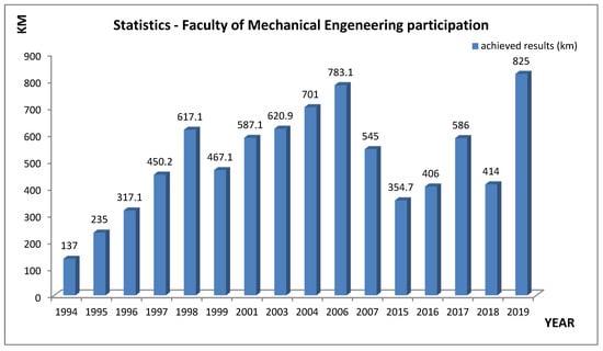
Figure 1.
Statistics of the team of the Faculty of Mechanical Engineering of the Technical University of Košice.
2. Experimental Vehicle and Conditions
One of the most important elements of the Shell Eco-Marathon race is the construction of the vehicle with the lowest possible weight, therefore special carbon materials are used for this purpose. The body is self-supporting and made especially for the pilot of the vehicle. A special manufacturing process is used to ensure a small body thickness while maintaining the highest rigidity. All components used in this experimental vehicle are selected according to several criteria, the most important of which are quality and the lowest possible weight. The placement of the individual components will be carried out in accordance with the idea of keeping the vehicle’s center of gravity as low as possible in order to ensure sufficient stability of the vehicle. As the race takes place on a multi-turn circuit, in addition to the low weight and sufficient rigidity of the vehicle, it is very important to have the correct geometry of the rotating wheels. When turning, each of the steered wheels moves in a different way because the inner and outer wheels go around a different turning radius. To achieve the best result in this competition, all possible passive resistances and losses should be ruled out as much as possible. One of these losses can be caused by the bad geometry of the steered wheels, which can cause the steered wheels to brake the entire vehicle when cornering. Despite the fact that the ultralight vehicle does not have shock absorbers, it is necessary to consider the rigidity of the axle in order to be able to support the wheel to some extent and return to its original position.
An important factor in the success of these races is not only the assembly of the engine with low consumption but also the reduction of wheel resistance, especially when cornering. Another integral part of the development of the experimental vehicle is the aerodynamic drag of the body, which has a great impact on its speed, stability, but especially on fuel consumption. The external aerodynamic shape of the bodywork must be designed to provide the best possible airflow while giving the driver sufficient space to ensure a safe view outside and to suit all the necessary components.
3. Development and Production of Vehicle
In 2019, more than 1500 students from 28 countries took part in the competition, spending 12 months designing or improving their energy-efficient vehicles. The Brooklands Racecourse, the world’s first motor racing circuit, featured 140 vehicles powered by a variety of energy sources. They competed in two main categories—Prototypes and UrbanConcept, each with vehicles powered by an internal combustion engine, an electric motor, and a battery, or hydrogen propulsion [,,,,]. When designing and developing a new body for 2019, the Faculty of Mechanical Engineering of the Technical University of Košice team placed particular emphasis on space savings, aerodynamic body shape, and, last but not least, sufficient rigidity of the body as a whole. An innovative design procedure has been chosen to optimize the interior of the body. The woman driver, which was to pilot a new prototype at the race in 2019, was completely scanned. Three optimal positions for the woman pilot in terms of ride comfort, the natural possibility of simple piloting of the prototype, and especially in terms of ensuring the greatest possible protection in the event of an accident were designed. To simulate real riding conditions, the woman pilot was scanned on an adjustable recliner, wore a safety helmet, which is also used in competitions, and held a prototype steering wheel in her hands, which was also made according to the woman pilot’s requirements (Figure 2).
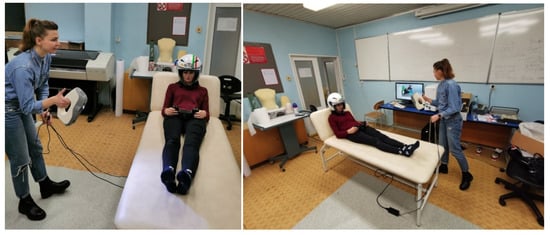
Figure 2.
Woman pilot scanning.
The woman pilot was scanned using the Artec Eva handheld 3D scanner by means of which it is possible to create a 3D model of medium dimensions relatively quickly depending on the complexity of the surface. The scanner has a wide range of applications in the technical field, from the automotive industry, construction to medical engineering. The ergonomic handle helps scan larger objects, such as the human body, which is important if the scans are for medical research (Figure 3).
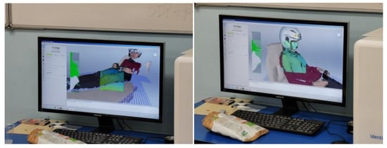
Figure 3.
Use of the Artec Evascanner.
The scanner is affordably priced and easy to use. Artec 3D is based in Luxembourg and its basic parameters are listed in Table 1.

Table 1.
Basic parameters of the Artec Eva scanner [,].
3.1. Methodology of Environment and Surroundings Preparation
The terms environment and surroundings are characterized by two different definitions. The environment is defined as the space of the whole room and the surrounding as the immediate proximity of the person being scanned. Within the methodology of preparation of the environment and the surroundings during the scanning process, the preparation and diagnostic room, regulation of the temperature and humidity of the environment, temperature in the room and its equipment are monitored. The room in which the person is scanned is to meet the basic requirement of ensuring a constant ambient temperature through air conditioning. The temperature range should be kept from 18 to 25 °C. At lower temperatures, the scanned person could quake and at higher temperatures could perspire, which would significantly affect scanning.
Another requirement is to darken the room in order to avoid sunlight when scanning, which is undesirable in the process itself. Sufficient artificial lighting significantly affects the quality of the obtained 3D model. The recommended artificial lighting is in the range of 30 to 50 lux. The noise of the room may also affect the model itself. This value should be a maximum of 50 dB so that the subject can concentrate. To work with the Artec Eva scanner, it is necessary to ensure a minimum distance of approximately 1 m between the scanner and the scanned person. Based on this requirement, the proposed room should have dimensions of at least 2 × 2 m or more.
3.1.1. Scanner Preparation Methodology
The preparation of the scanner itself is very simple, as it is not necessary to calibrate the scanner. First, make sure the scanner is not damaged. Then you need to plug the power cord in the battery accessory into both the scanner and the power outlet. Then the device is connected to the computer via the USB port. With this type of scanner, it is not possible to choose the optimal optics when scanning, nor to replace the lens. The scanner is ready for use if the green LED on the back of the scanner light is on when you turn it on. During the digitization process itself, it is necessary to manipulate the scanner, therefore a tripod is not necessary [].
3.1.2. Methodology of Subject Preparation
Before each scanning, the subject must be informed of the progress of the scanning and also of all the conditions under which the scanning will take place. It is important to remember that this is a safe and relatively fast scanning using structured white-light technology.
3.1.3. Methodology of Scanning
After mastering the individual steps of preparation of the environment, scanner, and subject, it is possible to proceed to the scanning methodology. According to the specified requirements, it is necessary to position the subject in the desired position. After stabilization, the scanning process begins. The remote meter shows a work surface that is in the range from 400 to 1000 mm, while the recommended distance of the scanner from the scanned object is about 600 to 700 mm []. Because ArtecStudio software creates SPROJ files, which are project files for the software, the models must be saved in STL format so that they can be opened on another device where Artec software is not available. The STL file format, an acronym for 3D printing technology called stereolithography, was created by 3D Systems. This file describes the three-dimensional surface geometry of the model and is most often used to export data to 3D printers from CAD software or other programmatic 3D modelers []. The export of scans takes a few minutes and depends mainly on the complexity of the object. These are usually large sets because the human body is complex in shape and different structures vary there [,,,,].
3.2. Chassis Design
After scanning the woman pilot and processing the obtained data, several body variants were modeled. From the obtained data from the scan, three woman-pilot models were first created in three different positions, on the basis of which three body variants for 2019 began to be designed and modeled (Figure 4).
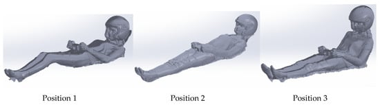
Figure 4.
Three scanned positions of the woman pilot.
As mentioned above, the woman pilot’s scans were used mainly to design the interior space of the body according to the woman pilot’s measurements to ensure a precise position for her with the ability to easily pilot the prototype and to ensure a sufficient view of the track. From the data obtained, position No. 3 (the one perpendicular) was evaluated as the least suitable for the design of a new body, because with this style of seating, the new body would have to be too high, which would have adverse effects on the center of gravity and overall balance of the prototype.
Another and one of the most important factors in body design was its aerodynamic shape. The suitable aerodynamic shape of the body minimizes air resistance when riding, which significantly increases the required body properties for Shell EcoMarathon races. In addition to the optimal aerodynamic shape of the body, the emphasis was also placed on creating sufficient space for the front and rear wheels, as well as for the entire drive unit. For the front wheels, which rotate, space had to be created for them to be rotated in such a way that the conditions of the turning radius specified by the competition regulations were met.
By grouping all the above-mentioned bodywork requirements, three body models were created on which aerodynamic airflow tests were performed (Figure 5).
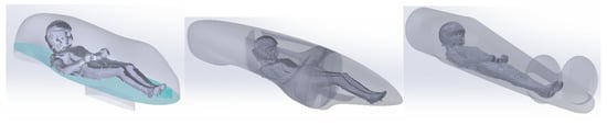
Figure 5.
Scanned positions of the woman pilot embedded in the body models.
3.3. Description of the Procedure for the Numerical Calculation of the Airflow around the Car
A domain representing flowing air with dimensions of 3 × 1.7 × 5 m (W × H × L) was created around the model. Due to the possibility of network compression, and thus speeding up the calculation, the domain was divided into two parts. Outer with coarse and inner with fine unstructured mesh. Due to the fact that the flow around the car was solved, the car model itself was not subject to calculation (Figure 6). Numerical calculation of the airflow was solved with the help of Ansysn software.
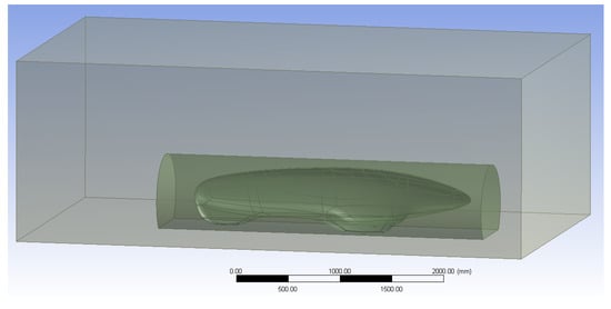
Figure 6.
3D model for numerical solution of flow.
The model was then divided into a finite number of tetrahedron volume elements. The outer domain was created with a mean element size of 60 mm, the inner with a size of 30 mm, and at the point of contact between air and the car the mesh was compressed to 10 mm. For the correct simulation of the boundary layer, mesh densification with a first element size of 1.5 mm and a number of layers of 6 was created on the contact surface. In total, the model meshes showed an average of 2.6 million elements (Figure 7).
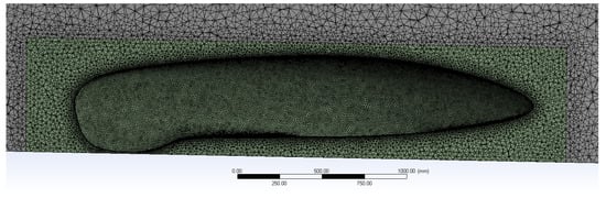
Figure 7.
View of the longitudinal section of the mesh.
The solution was considered with air flow at a speed of 25 and 40 km/h and a temperature of 25 °C. The model solved the isothermal flow of a viscous fluid with the turbulence model k-ε. Boundary conditions included air inlet to a model with a defined velocity, air outlet at zero relative static pressure, and outer walls of a domain with a defined zero shear stress (the floor was designed as a smooth wall with shear stress calculation with 300 iterations to achieve the residues below 10−5).
The aim of the numerical calculation was to determine the resistance coefficients of individual body models (Figure 8, Figure 9 and Figure 10). The parameter was determined for two speeds with its subsequent averaging.
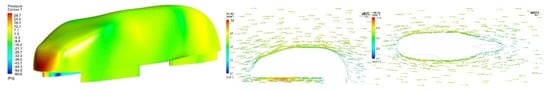
Figure 8.
Air resistance simulation for body no. 3.
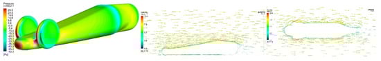
Figure 9.
Air resistance simulation for body no. 2.
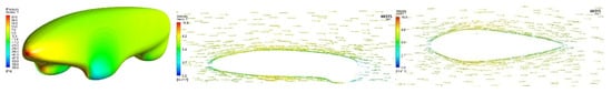
Figure 10.
Air resistance simulation for body no. 1.
Based on data, the body no. 1 was chosen as the optimum because it had the lowest air resistance values. Air resistances were simulated at speeds of 25 and 40 km/h (Table 2).
Table 2.
Results from numerical calculations.
3.4. Modification of the Engine
The engine itself is one of the most important components of a vehicle while achieving the lowest possible fuel consumption. The Honda GX35 engine was used as a basis for the modification, which can normally be purchased in authorized stores. This model is used by many competitors. The basic goal was to reduce the consumption of this mass-produced engine. Due to the regulations of the competition, the engine could not be started by hand (pulling the cable), it had to be equipped with an electric starter. Several important facts were taken into account when designing the location of the starter:
- ✓ Susceptibility of the Hall sensor (engine speed sensor) to the proximity of metal parts,
- ✓ Free wheel mounting in the starter gear,
- ✓ The need to use a centrifugal clutch,
- ✓ The size of the starter, its convenient location, easy access for power cables,
- ✓ Location of the sprocket and its possible quick change (to change the gear),
- ✓ Fast and efficient assembly/disassembly in the event of a race failure (Figure 11).
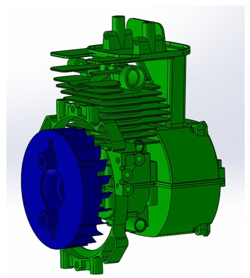
Figure 11.
Honda GX35 serial engine in SolidWorks environment.
Subsequently, the connection of starting gears with a centrifugal clutch and a permanent gear was proposed. At the same time, the weight of the fly wheel increased, which was necessary to set the low idle speed of the engine. The most complicated part in terms of production was the main starter holder, which was professionally called the “spider”. It was milled from one piece to a five-axis CNC milling machine. This holder centered the centrifugal clutch, while holding the centrifugal clutch carrier, which transmits the engine torque to the driven wheel (Figure 12).
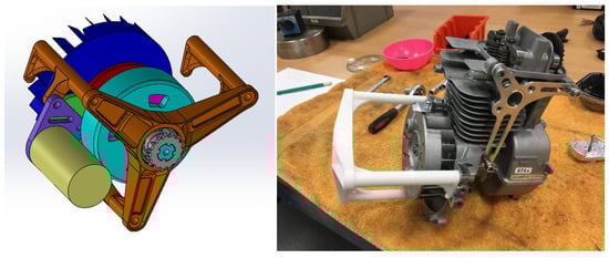
Figure 12.
Verification of placing the starting system using 3D printing.
The most significant change was the modification of the Honda GX35 engine. The main goal was to reduce consumption and reduce engine speed while maintaining a torque of 1.5 Nm. The priority was to adjust the engine timing, which was not an easy task, as one cam controlled both the intake and exhaust valves at the same time. Due to the required change in valve timing, it was necessary to design a separate control of both the intake and exhaust valves while maintaining only one cam. This was achieved by adjusting the valve tappets and the cam itself. This has made it possible to adjust the time, angle and course of the opening of the individual valve in various ways in order to improve the filling/emptying of the combustion chamber and to make maximum use of the energy contained in the fuel. For the best possible filling and emptying of the cylinder, the intake/exhaust ducts on the cylinder head and the combustion space around the valve seats were also modified (Figure 13).
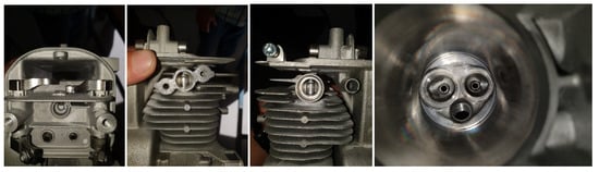
Figure 13.
Modification of valve tappets, intake/exhaust duct and combustion chamber.
Subsequently, the compression ratio was changed. Several variants of pistons were produced, each of which corresponded to a different compression, while each variant of the piston had two types—two and three grooves (grooves for piston rings). Also with these components, the pistons were first printed on a 3D printer before production itself (Figure 14 and Figure 15).
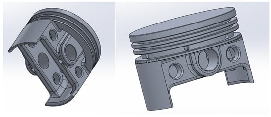
Figure 14.
Piston models in Solidworks.
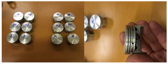
Figure 15.
Manufactured pistons with different numbers of grooves for piston rings and different compression ratios.
This was followed by the placement of the carburetor with a throttle valve with an injector. It was necessary to design the throttle so that it could be easily and quickly dismantled for inspection purposes during the race.
At the same time, it was necessary to think about electronic opening/closing of the damper in order to significantly facilitate the control of the engine for the pilot (Figure 16).
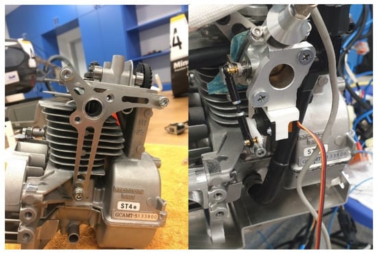
Figure 16.
Mounted throttle system with electronic opening control and injector.
During the preparations for the Shell-Eco Marathon 2019 race, the pistons were gradually changed and power and consumption were measured on the engine brake. For each piston, it was necessary to set the engine control program so as to achieve the lowest possible fuel consumption with the highest possible torque. The measured values were compared and put together the engine with the most efficient parameters for the competition.
In the beginning, the original, serial engine was measured. It was already clear during the preparation of the technical documentation for the production of pistons that if the effort is to achieve low consumption, it will be necessary to get the engine characteristics completely elsewhere. Due to the fact that the original engine was not designed for low consumption, it was necessary to keep the operating speed of the engine as low as possible. To do this, it was necessary to design the engine so that it had the lowest idling speed. For comparison, the original engine had a working speed of 7000 RPM and an idle level of 3500 RPM. The proposed modifications to the engine got a working speed of 3500 RPM and idled up to the level of 1500 RPM, which was extremely demanding. The fly wheel also had to be modified with regard to electronic starting. All this while maintaining low weight and easy assembly/disassembly from the vehicle. The aim was to achieve the lowest possible engine consumption at the highest torque.
The monitored values, which were measured and evaluated, were based on the torque and consumption at a given speed. Speed was measured from idle to maximum. The value of torque and consumption was measured in differences of 250 RPM, which gave a large range of measured quantities and helped in further design of gear ratios in the transmission. Engine consumption was evaluated in grams per kWh. The engine was run under load at the selected speed for 1 min and then the consumption was measured. The following graphs show the engine torques and consumption (Figure 17, Figure 18, Figure 19, Figure 20, Figure 21, Figure 22, Figure 23 and Figure 24). The final evaluation of the achieved values is summarized in the final table (Table 3).
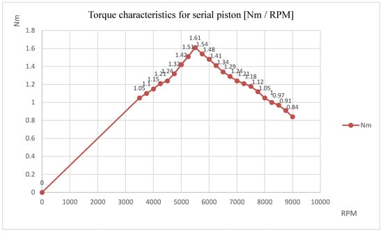
Figure 17.
Engine torque characteristics for serial piston.
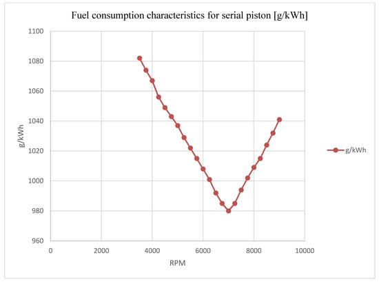
Figure 18.
Fuel consumption characteristics for serial piston.
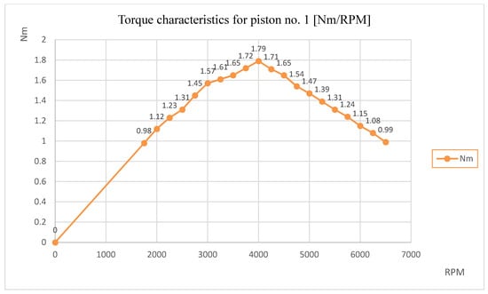
Figure 19.
Engine torque characteristics for piston no. 1.

Figure 20.
Fuel consumption characteristics for piston no. 1.
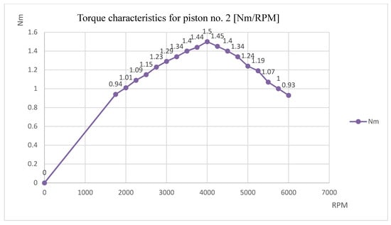
Figure 21.
Engine torque characteristics for piston no. 2.

Figure 22.
Fuel consumption characteristics for piston no. 2.
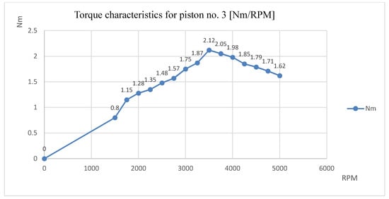
Figure 23.
Engine torque characteristics for piston no. 3.
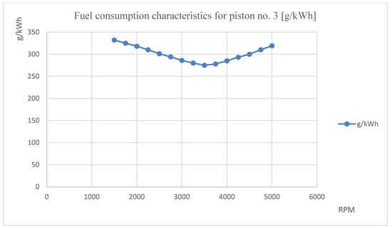
Figure 24.
Fuel consumption characteristics for piston no. 3.
Table 3.
Comparison of engine characteristics using different pistons.
Based on the data, piston no. 3 (blue line) and at the same time the characteristics of the torque engines were compared with the piston of the original series engine (red line) and with the optimum, i.e., with the piston 3 (Figure 25).
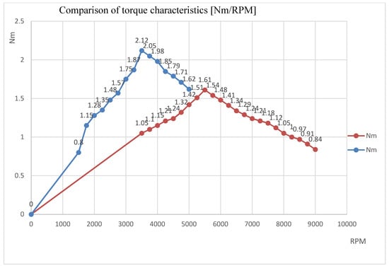
Figure 25.
Comparison of torque characteristics with serial piston and piston no. 3 (optimum).
At the same time, the consumption of the engines of the original serial piston (red line) and optimum no. 3 (blue line) was compared (Figure 26).
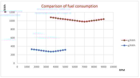
Figure 26.
Comparison of consumption of engines with serial piston and piston no. 3.
3.5. Development and Production of Rear Axle
After a successful mechanical redesign of the engine, a complete rear axle came into play. It was necessary to design a sufficiently rigid axle, where the emphasis was again on simple assembly and disassembly of all components. All this had to be designed so that the whole propulsion mechanism would fit into the original body from 2018 (Figure 27).
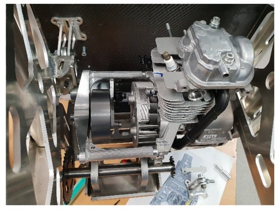
Figure 27.
Mounted propulsion mechanism in the rear axle.
As it was necessary to reduce the center of gravity, the engine with gears was given its own bracket, which was mounted to get her with the engine from the bottom of the rear axle and was placed as low as possible, as the original body allowed. This ensured a significant reduction in the center of gravity and extremely easy removal of the engine from the vehicle in the event of a fault. The axle itself was designed from aluminum alloy, which was guaranteed weld ability. The axle was laser fired from sheet metal, bent and transverse enforcements were welded. This has resulted in high rigidity, low weight and cost-effectiveness in the production of the rear axle. The rear wheel was mounted from below, so it had a natural stop and during the race the wheel could not come loose and the axle could be damaged (Figure 28).
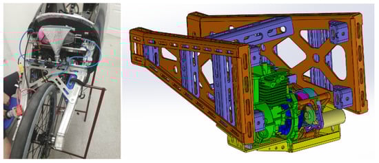
Figure 28.
Completely assembled rear axle.
3.6. Front Axle Development and Manufacturing
Geometry is the most important thing on the front axle. Correct geometry adjustment ensures smooth wheel balancing as the steering wheel turns. The Causant system was used to meet this condition.
When developing the new front axle, in addition to the correct setting, emphasis was placed on the lowest possible weight with the highest possible rigidity. The basic point was to choose a suitable material.
The first version of the front axle consisted of four separately laser cut and bent parts that were welded together to form the front axle. Material 5754 was chosen for its high strength, which is close to conventional steel at a significantly lower weight. Another advantage of this material is its good weld ability, which was used in this case. Simulations have shown that this design solution will be suitable for use in Shell Eco Marathon races. The front hubs were attached to the beveled axle for optimal deflection of the front wheels. The whole axle was then laminated to a self-supporting structure to form a single unit (Figure 29).
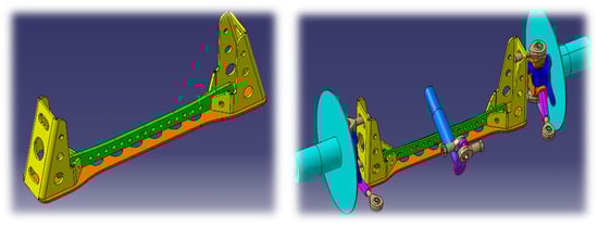
Figure 29.
Front axle no. 1 in SolidWorks environment.
Due to the unforeseen circumstances that may arise during the competition, it was decided to proceed with the development of a new front axle for 2019, where even greater rigidity was ensured, even at the cost of increased weight. The original idea of welding the front axle from several parts was replaced by milling directly from duralumin alloy 7075 in one piece (Figure 30).
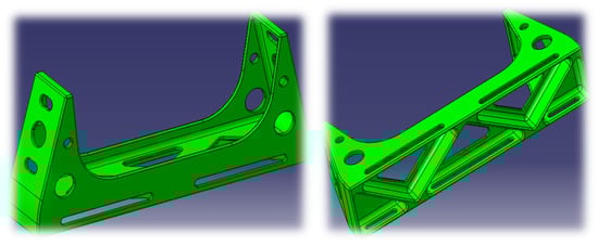
Figure 30.
Front axle no. 2 in Solidworks environment.
This material is used mainly in the aviation industry due to its high strength, which surpasses conventional steels at a still relatively low weight. One of the disadvantages of this material is that it cannot be welded, which is why we have chosen the concept of one-piece milling. The front axle for 2019 retained the dimensions and wheel hubs, where the correct setting of the front wheel geometry had already been tested. This conversion of the front axle exceeded the first by 750 g (Figure 31).
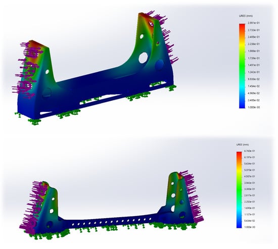
Figure 31.
Comparison of load simulations of both front axles.
When comparing the deformation simulations, it is obvious that this conversion of the front axle has the maximum possible shift at the point of attachment of the front hubs by more than half.
4. Conclusions
Automotive production is an area where innovation has a large share in changes not only in production but also in development itself. The aim of these changes is not only to increase performance, minimize material costs, or reduce emissions but ultimately to improve design and ergonomics. Through the international Shell Eco Marathon competition, the company Shell is giving the opportunity to present new designs that are not yet part of mass car production but support the creativity of young students and their ideas, which may become the basis for innovative automotive manufacturing processes and processes in the future. Based on these changes (body design and engine modifications), the Faculty of Mechanical Engineering of the Technical University of Kosice team achieved a new Slovak record (825 km) in the number of kilometers traveled per 1 L of fuel. The vehicle is a good platform for the application of autonomous control. Overall production cost of the whole vehicle was in the range 40,000–60,000 €. The scientific conclusions can be summarized as follows:
- -
- Increasing the height of the piston from the piston pin by 1.5 mm increased the compression ratio by 57%.
- -
- Increased compression ratio and tuning engine control unit reduced engine consumption by 28%.
- -
- Increase in intake and exhaust ducts by 1.3 mm in diameter increased engine filling efficiency by 22%.
- -
- Increase of flywheel weight by 15% reduced engine idle speed by 42%.
- -
- Engine modifications can contribute to the research and development of technology based on Homogeneous Charge Compression Ignition (HCCI).
Author Contributions
Conceptualization, J.Ž., M.P. (Michal Puškár) and M.P. (Miroslav Palko); Formal analysis A.N., J.Ž. and T.B.; Investigation M.P. (Maroš Palko), M.P. (Michal Puškár) and A.N.; Software V.K., J.I. and M.P. (Miroslav Palko); Validation T.B., N.Š. and M.P. (Maroš Palko); Visualization V.K. and M.P. (Miroslav Palko); Writing—original draft M.P. (Maroš Palko) and T.B.; Project administration M.P. (Michal Puškár), A.N. and N.Š. All authors have read and agreed to the published version of the manuscript.
Funding
This paper was developed within the projects implementation: VEGA Nr. 1/0316/18 “Application of Paradigms in Metrotomography”, KEGA 006TUKE-4/2020 “Implementation of Knowledge from Research Focused on Reduction of Motor Vehicle Emissions into the Educational Process” and University Science Park TECHNICOM for Innovation Application Supported by Knowledge Technology—Phase 1, ITMS: 26220220182, supported by the Research and Development Operational Program funded by the ERDF. “This work was supported by the Slovak Research and Development Agency under the contract No. APVV-16-0259”.
Conflicts of Interest
The authors declare no conflict of interest.
References
- Anwar, H. Calibrating projector flexibly for a real-timeactive 3D scanning system. Optik 2018, 158, 1088–1094. [Google Scholar] [CrossRef]
- Čelko, J.; Kováč, M.; Kotek, P. Analysis of the Pavement Surface Texture by 3D Scanner. Transp. Res. Procedia 2016, 14, 2994–3003. [Google Scholar] [CrossRef]
- Bouachir, O.; Aloqaily, M.; Ridhawi, I.A.; Alfandi, O.; Salameh, H.B. UAV-Assisted Vehicular Communication for Densely Crowded Environments. NOMS 2020-2020 IEEE/IFIP Netw. Oper. Manag. Symp. 2020. [Google Scholar] [CrossRef]
- Brestovič, T.; Jasminská, N.; Čarnogurská, M.; Puškár, M.; Kelemen, M.; Fiľo, M. Measuring of Thermal Characteristics for Peltier Thermopile Using Calorimetric Method. Measuring of Thermal Characteristics for Peltier Thermopile Using Calorimetric Method. Measurement 2014, 53, 40–48. [Google Scholar] [CrossRef]
- Uradnicek, J.; Kraus, P.; Musil, M.; Bachraty, M. Modeling of frictional stick slip effect leading to disc brake noise vibration and harshness. In Proceedings of the 23rd International Conference, Svratka, Czech Republic, 15–18 May 2017; pp. 1002–1005. [Google Scholar]
- Khadim, S.; Riaz, F.; Jabbar, S.; Khalid, S.; Aloqaily, M. A non-cooperative rear-end collision avoidance scheme for non-connected and heterogeneous environment. Compu. Commun. 2020, 150, 828–840. [Google Scholar] [CrossRef]
- Kraus, P.; Uradnicek, J.; Musil, M.; Bachraty, M.; Hulan, T. Thermo-Structural brake squeal fem analysis considering temperature dependent thermal expansion. Eng. Mech. 2018 Proc. 2018, 24, 429–432. [Google Scholar]
- Musil, M.; Suchal, A.; Uradnicek, J.; Kraus, P. The Complex eigenvalue analysis of brake squeal using finite element method. In Proceedings of the 22nd International Conference, Svratka, Czech Republic, 9–12 May 2016; pp. 406–409. [Google Scholar]
- Herbort, S.; Gerken, B.; Schugk, D.; Wohler, C. 3D rangescanenhancementusing image-basedmethods. ISPRS J. Photogramm. Remote Sens. 2013, 84, 69–84. [Google Scholar] [CrossRef]
- Brezinova, J.; Hudak, R.; Guzanova, A.; Draganovská, D.; Ižaríková, G.; Koncz, J. Direct Metal Laser Sintering of Ti6Al4V for Biomedical Applications: Microstructure, Corrosion Properties, and Mechanical Treatment of Implants. Metals 2016, 6, 171. [Google Scholar] [CrossRef]
- Hudák, R.; Šarik, M.; Dadej, R.; Živčák, J.; Harachová, D. Material and Thermal Analysis of Laser Sinterted Products. Acta Mech. Autom. 2013, 7, 15–19. [Google Scholar] [CrossRef]
- Živčák, J.; Šarik, M.; Hudák, R. FEA Simulation of Thermal Processes during the Direct Metal Laser Sintering of Ti64 Titanium Powder. Measurement 2016, 94, 893–901. [Google Scholar] [CrossRef]
- Tlach, V.; Cisár, M.; Kuric, I.; Zajačko, I. Determination of the Industrial Robot Positioning Performance. Modern Technologies in Manufacturing. Available online: https://www.matec-conferences.org/articles/matecconf/abs/2017/51/matecconf_mtem2017_01004/matecconf_mtem2017_01004.html (accessed on 22 June 2020).
- Brezinova, J.; Guzanova, A. Friction Conditions during the Wear of Injection Mold Functional Parts in Contact with Polymer Composites. J. Reinf. Plast. Compos. 2010, 29, 1712–1726. [Google Scholar] [CrossRef]
- Lamas Galdo, M.I.; Castro-Santos, L.; Rodriguez Vidal, C.G. Numerical analysis of NOx reduction using ammonia injection and comparison with water injection. J. Mar. Sci. Eng. 2020, 8, 109. [Google Scholar] [CrossRef]
- Puškár, M.; Bigoš, P.; Kelemen, M.; Markulik, Š.; Puškárová, P. Method for accurate measurement of output ignition curves for combustion engines. Measurement 2013, 46, 1379–1384. [Google Scholar] [CrossRef]
- Kučera, P.; Píštěk, V. Testing of the Mechatronic Robotic System of the Differential Lock Control on a Truck. Int. J. Adv. Robot. Syst. 2017, 14, 1–7. [Google Scholar] [CrossRef]
- Kniewald, D.; Guzanova, A.; Brezinova, J. Utilization of Fractal analysis in strength prediction of adhesively-bonded joints. J. Adhes. Sci. Tech. 2008, 22, 1–13. [Google Scholar] [CrossRef]
- Puškár, M.; Bigoš, P. Output Performance Increase of Two-stroke Combustion Engine with Detonation Combustion Optimization. Strojarstvo: Časopis za teoriju i praksu u strojarstvu 2010, 52, 577–587. [Google Scholar]
- Kučera, P.; Píštěk, V.; Prokop, A.; Řehák, K. Measurement of the powertrain torque. In Proceedings of the Engineering Mechanics, Svratka, Czech Republic, 14–17 May 2018; pp. 449–452, ISBN 978-80-86246-88-8. [Google Scholar]
- Puškár, M.; Bigoš, P. Method for accurate measurements of detonations in motorbike high speed racing engine. Measurement 2012, 45, 529–534. [Google Scholar] [CrossRef]
- Píštěk, V.; Klimeš, L.; Mauder, T.; Kučera, P. Optimal design of structure in rheological models: An automotive application to dampers with high viscosity silicone fluids. J. Vibroeng. 2017, 19, 4459–4470. [Google Scholar] [CrossRef][Green Version]
- Kuric, I. New Methods and Trends in Product Development and Planning. In Proceedings of the 1st International Conference on Quality and Innovation in Engineering and Management (QIEM), Cluj Napoca, Romania, 17–19 March 2011; pp. 453–456, ISBN 978-973-662-614-2. [Google Scholar]
- Kus, A. Implementation of 3D Optical Scanning Technology for Automotive Applications. Sensors 2009, 9, 1967–1979. [Google Scholar] [CrossRef] [PubMed]
- Maletič, M.; Maletič, D.; Dahlgaard, J.; Dahlgaard-Park, S.; Gomiscek, B. Effect of sustainability-oriented innovation practices on the overall organizational performance: An empirical examination. Total Quality Manag. Bus. Excell. 2019, 27, 1171–1190. [Google Scholar] [CrossRef]
- Panda, A.; Orendáč, P. Nové materiály pre automobilový priemysel. Transfer Inovácií 2016, 33, 12–15. [Google Scholar]
- Puškár, M.; Bigoš, P.; Puškárová, P. Accurate measurements of output characteristics and detonations of motorbike high-speed racing engine and their optimization at actual atmospheric conditions and combusted mixture composition. Measurement 2012, 45, 1067–1076. [Google Scholar] [CrossRef]
- Puškár, M.; Brestovič, T.; Jasminská, N. Numerical simulation and experimental analysis of acoustic wave influences on brake mean effective pressure in thrust-ejector inlet pipe of combustion engine. Int. J. Veh. Des. 2015, 67, 63–76. [Google Scholar] [CrossRef]
- Kučera, P.; Píštěk, V. Prototyping a System for Truck Differential Lock Control. Sensors 2019, 19, 3619. [Google Scholar] [CrossRef] [PubMed]
- Čarnogurská, M.; Marián, L.; Michal, P.; Lengyelová, M.; Václav, J.; Širillová, L. Measurement and Evaluation of Properties of MSW Fly Ash Treated by Plasma. Measurement 2015, 62, 155–161. [Google Scholar] [CrossRef]
© 2020 by the authors. Licensee MDPI, Basel, Switzerland. This article is an open access article distributed under the terms and conditions of the Creative Commons Attribution (CC BY) license (http://creativecommons.org/licenses/by/4.0/).