Article

Hybrid Data Hiding Based on AMBTC Using Enhanced Hamming Code

1
Department of Computer Engineering, Sejong University, Seoul 05006, Korea
2
Department of Computer Science and Information Engineering, National Dong Hwa University, Hualien 97401, Taiwan
3
Key Laboratory of Jiangxi Province for Image Processing and Pattern Recognition, Nanchang Hangkong University, Nanchang 330063, China
4
School of Electrical and Electronic Engineering, College of Engineering, Yonsei University, Seoul 120749, Korea
*
Authors to whom correspondence should be addressed.
These authors contributed equally to this work.
Appl. Sci. 2020, 10(15), 5336; https://doi.org/10.3390/app10155336
Submission received: 3 July 2020 / Revised: 30 July 2020 / Accepted: 30 July 2020 / Published: 2 August 2020

Abstract

:
The image-based data hiding method is a technology used to transmit confidential information secretly. Since images (e.g., grayscale images) usually have sufficient redundancy information, they are a very suitable medium for hiding data. Absolute Moment Block Truncation Coding (AMBTC) is one of several compression methods and is appropriate for embedding data due to its very low complexity and acceptable distortion. However, since there is not enough redundant data compared to grayscale images, the research to embed data in the compressed image is a very challenging topic. That is the motivation and challenge of this research. Meanwhile, the Hamming codes are used to embed secret bits, as well as a block code that can detect up to two simultaneous bit errors and correct single bit errors. In this paper, we propose an effective data hiding method for two quantization levels of each block of AMBTC using Hamming codes. Bai and Chang introduced a method of applying Hamming (7,4) to two quantization levels; however, the scheme is ineffective, and the image distortion error is relatively large. To solve the problem with the image distortion errors, this paper introduces a way of optimizing codewords and reducing pixel distortion by utilizing Hamming (7,4) and lookup tables. In the experiments, when concealing 150,000 bits in the Lena image, the averages of the Normalized Cross-Correlation (NCC) and Mean-Squared Error (MSE) of our proposed method were 0.9952 and 37.9460, respectively, which were the highest. The sufficient experiments confirmed that the performance of the proposed method is satisfactory in terms of image embedding capacity and quality.

1. Introduction

Recently, the Internet space has become like a single trading world where almost all digital content is distributed because every trading system is connected by high speed Internet, such as 5G. Many people distribute digital content in this space and are constantly consuming digital content. The problem with this digital space is that a copyright protection problem occurs because digital content is easily redistributed, copied, and modified by illegal users. There are various solutions to this problem, but the commonly used method is digital watermarking [1,2,3], which is used to protect the integrity and reliability of digital media.
Besides watermarking technology, Data Hiding (DH) technology is the most commonly used method of concealing information in digital media. The DH [4,5,6] technique can be used in various fields, such as digital signatures, fingerprint recognition, authentication, and secret communication. It has been proven various times that DH could be used for secret communication, as well as the protection of the copyright of digital content. The people who use Internet communication know that the Internet is not a fully protected communication channel due to the many attackers. However, secret communication using DH can safely protect secret messages in digital cover media from the incomplete Internet channel.
DH may achieve the role of a secret communication strategy only when it satisfies two important criteria. First, the quality of the cover image (including data) should not be significantly different from the quality of the original image, since the cover image must not be detected by attackers while it is transmitted. Second, it must have the ability to transmit many secret data to the receiver securely.
The DH method is mainly conducted in two domains, namely the spatial domain and the frequency domain. In the spatial domain, a secret bit is concealed in the pixels of a host image directly. In the case of DH based on the spatial domain, it is applied to a grayscale image; even though the four Least Significant Bits (LSBs) [7,8,9,10] of each pixel are used for information hiding, they may not be detected by the Human Visual System (HVS).
Reversible DH [11,12,13,14,15,16,17,18,19,20] is a special case of DH in the academic community. In RDH, after the embedded bits are extracted, the stego image can be recovered back to the original image without distortion. The representative RDH methods are Difference Expansion (DE) [11,12], image compression [13], Histogram Shifting (HS) [14,15], Prediction-Error expansion (PE) [16,17], and encrypted images [18,19] for privacy preserving.
In the frequency domain, a cover image is converted into a frequency form, and then, the data are concealed in the coefficients of the frequency. The two most common methods based on the frequency domain are Discrete Cosine Transform (DCT) [21,22] and Discrete Wavelet Transform (DWT) [23]. Since changing the coefficient adversely affects the image quality, it is necessary to find and change the positions of the coefficient that have a relatively small influence on the image quality during data insertion. Spatial domain methods have the merit of the ability to conceal many secret data compared to the frequency domain methods, and the quality of the image is better, while they have the demerits of compression, noise, and filtering attacks compared to the frequency domain methods. Meanwhile, excellent compression images like JPEG are preferred as digital media, because the file size is small compared to the raw images and is well transmitted. For this reason, many researchers closely studied the watermarking and DH methods based on JPEG compression a long time ago.
Block Truncation Coding (BTC) [24] is one of the compression methods, and the configuration of the BTC is very simple compared to conventional JPEG. Thus, the computation time of BTC is much shorter than that of JPEG, and the quality of an image based on BTC is not significantly deteriorated compared to that of the original image. For this reason, it seems many researchers are interested in DH based on Absolute Moment Block Truncation Coding (AMBTC) [25,26,27], originated from BTC recently. Chuang and Chang [28] proposed a DH method based on AMBTC replacing the bitmaps of smooth blocks with the secret bits after dividing the blocks of an image into smooth blocks and complex blocks directly. It is called the Direct Bitmap Substitution (DBS) method. The merit of this method is that it may control the quality of the stego image by adjusting the threshold T ( = b a ) because the number of blocks using DH is decided according to the threshold value T. Here, a and b are quantization levels for each block in AMBTC. With the increase of the threshold T, the embedding capacity will be increased, while the image quality will be worse. In the case of decreasing the threshold T, the quality of the image will be improved, but the embedding capacity may be reduced.
Ou and Sun [29] introduced a way to embed data in the bitmaps of smooth blocks and proposed a method to reduce the distortions of the image by adjusting two quantization levels through re-computation, but the original image is required for re-calculation. Bai and Chang [30] proposed a way to embed secret data by applying a Hamming Code, i.e., HC(7,4) [7], to two quantization levels and bitmaps of AMBTC, respectively. When HC (7,4) is used for a complex block of AMBTC, it may be undesirable for high image quality. Kumar et al. [31] used two threshold values to increase the capacity of DH without significantly improving the image quality. Chen et al. [32] proposed a lossless DH method using the order of two quantization levels in t r i o . This method is named the Order of Two Quantization Level (OTQL) method, which can conceal one bit per a block. For example, to store the bit “1”, the order of two quantization levels, a and b, is reversed as t r i o ( b , a , B M ) . This method does not change the coefficients of both quantization levels, so it does not affect the quality of the image.
Hong [33] proposed a DH using Pixel Pair Matching (PPM) [34], where PPM is applied to the quantization levels; while the existing OTQL and DBS are used together for complex and smooth blocks, respectively. In 2017, Huang et al. [35] proposed a scheme for hiding data using pixel differences (hidden bits = l o g 2 T : derived from the difference expansion method) at two quantization levels and introduced a method to adjust the differences in the quantization levels to maintain image quality. This method is also a hybrid method by using OTQL and DBS as well. Chen and Chi [36] sub-divided less complex blocks and highly complex blocks. In 2016, Malik et al. [37] introduced a DH based on AMBTC using a two bit plane and four quantization levels. The merit of this method is the high payload, and the demerit is the decrease in the compression rates.
The motivations to propose a DH method using the Hamming code based on the image compressed with AMBTC are as follows. First, AMBTC is suitable for DH because it has reasonable compression performance, very low computational complexity, and (although not many) redundant bits. In addition, DH is relatively less studied for grayscale images. Second, the Hamming code is very efficient for redundant bits, such as for grayscale images. This has been demonstrated in previous studies [7,10]. However, since the image compressed with AMBTC has fewer redundant bits than the grayscale image, the embedding of enough secret bits at two quantization levels results in a negative effect on the image in the decoding of the bitmap. Third, Bai and Chang [30] attempted to conceal data at two quantization levels, but this did not achieve optimized performance. Therefore, it is essential to develop an optimized method in the DH process.
The main contributions of this paper are summarized as follows:
(i)
We introduce a general framework for DH based on AMBTC with the minimal squared error by the optimal Hamming code using a Lookup Table (LUT).
(ii)
Our method calculates the codeword corresponding to the minimum distance from the standard array of the (7,4) Hamming code table and then extracts the corresponding code. The method has little effect on program performance and can be easily conducted.
(iii)
We provide a comparative analysis and evaluate the efficiency based on the specified criteria.
(iv)
Sufficient experimental results are used to show the effectiveness and advantages of the proposed method.
The rest of this paper is organized as follows. Section 2 gives the introduction of the background research. The proposed method is described in detail in Section 3. The experimental results are analyzed in Section 4. Section 5 draws the conclusions.

2. Preliminaries

2.1. AMBTC

Absolute Moment Block Truncation Coding (AMBTC) [25] efficiently improves the computation time of Block Truncation Coding (BTC) and improves the image quality over BTC. The basic configuration of one block in AMBTC is two quantization levels and one bitmap, while one block is compressed by preserving the moment. Here, the two quantization values are obtained by calculating the higher mean and the lower mean of each block. For AMBTC compression, the grayscale image is first divided into ( k × k ) blocks without overlapping, where k can determine the compression level by ( 4 × 4 ), ( 6 × 6 ), ( 8 × 8 ), etc. AMBTC adopts block-by-block operations. For each block, the average pixel value is calculated by:
x ¯ = 1 k × k i = 1 k 2 x i
where x i represents the ith pixel value of this block with a size of k × k . All pixels in this block are quantized into a bitmap b i (zero or one); that is, if the corresponding pixel x i is greater than or equal to the average ( x ¯ ), it is replaced with “1”, otherwise it is replaced with “0”. Pixels in each block are divided into two groups, “1” and “0”. The symbols t and k 2 t refer to the numbers of pixels in the “0” and “1” groups, respectively. The means a and b of the two groups indicate the quantization levels of the groups “0” and “1”. The two quantization levels are calculated by Equations (2) and (3).
a = 1 t x i < x ¯ x i
b = 1 k 2 t x i x ¯ x i
where a and b are also used to reconstruct AMBTC.
b i = 1 , if x i x ¯ , 0 , if x i < x ¯ .
g i = a , if b i = 0 , b , if b i = 1 .
The bitmap is obtained from Equation (4), and the compressed block is simply uncompressed by using Equation (5); that is, the compressed code unit, t r i o ( a , b , B M ) , may be obtained by using Equations (2)–(5). The image block is compressed into two quantization levels a, b, and a Bitmap (BM) and can be represented as a t r i o ( a , b , B M ) . A BM contains the bit-planes that represent the pixels, and the values a and b are used to decode the AMBTC compressed image by using Equation (5).
Example 1.
Here, we describe the encoding and decoding procedure of one block of a grayscale image using an example. Figure 1a is a grayscale block, and the mean value of the pixels is 106. By applying Equations (2)–(4) on (a), we can obtain the bitmap as shown in (b) and two quantization levels ( a = 102 ; b = 107 ). The basic unit of each block is t r i o ( a , b , B M ) = (102, 107, 0101111111011001). Using the information of the t r i o and Equation (5), the decoded grayscale block in (c) is reconstructed.

2.2. Hamming Code

The Hamming Code (HC) [38] is a single error-correcting linear block code with a minimum distance of three for all the codewords. In HC( n , k ), n is the length of the codeword, k is the number of information bits, and ( n k ) is the number of parity bits.
Let x be a k bit information word. The n bit codeword y is created by using y = x G , where G is the k × n generator matrix. Let e = y y ˜ be the error vector that determines whether an error occurred while sending y. If e = 0 , no error occurs, and y ˜ = y .
Otherwise, the weight of e represents the number of errors. Let H be a ( n k ) × n parity matrix with the relation of G · H T = [ 0 ] k × ( n k ) . Let us assume that the codeword y ˜ has an error like e = ( y y ˜ ) . In this case, we could correct one error ( e = y y ˜ ) from the codeword y ˜ by using the syndrome S = y ˜ · H T , where the syndrome denotes the position of the error in the codeword. As show in Equation (6), the error e can be obtained.
y ˜ · H T = ( e y ) · H T = e · H T + y · H T ( y · H T ) = ( x · G ) · H T = x · ( G · H T ) = 0 ) = e · H T + 0 = e · H T
Consider HC(7,4) with the following parity matrix.
H = 0 0 0 1 1 1 1 0 1 1 0 0 1 1 1 0 1 0 1 0 1
For example, assuming that one error bit occurred in y (e.g., the second bit from the left in e = ( e 1 , e 2 , , e 7 ) = ( 0 1 ̲ 00000 ) , we may obtain the error position and recover the one bit error from the codeword y by calculating the syndrome S ( = y · H T = ( 010 ) ) .

2.3. Bai and Chang’s Method

For DH, the AMBTC algorithm is applied to the original cover image to obtain a low mean, a high mean, and a bitmap for every block. Then, the secret message is concealed in the AMBTC compressed t r i o ( a , b , B M ) . The merit of AMBTC is that it achieves a higher payload compared to other DH schemes performed in the compression domain. Here, it performs AMBTC DH in two phases. The method proposed by Bai and Chang is composed of two stages. One of them is to embed three bits in two quantization levels in t r i o ( a , b , B M ) by using HC(7, 4). The detailed process of this method is as follows.
Step 1:
For each t r i o , obtain seven bits from the two pixels at two quantization levels, and rearrange the seven bits to form a seven bit unit. Let a = ( a 8 a 7 a 6 a 5 a 4 a 3 a 2 a 1 ) and b = ( b 8 b 7 b 6 b 5 b 4 b 3 b 2 b 1 ) be the two original pixels. The rearranged seven bit unit is obtained by y = ( a 4 , a 3 , a 2 , a 1 | | b 3 , b 2 , b 1 ) , where the symbol | | denotes that the four bits from a are concatenated with the three bits from b. Three secret message bits ( m = ( m 1 , m 2 , m 3 ) ) are read from the secret bit set M.
Step 2:
Compute the syndrome S ( = H y m ) of the codeword y, and then, the value is changed into a decimal value and is assigned to the variable i. To obtain the stego codeword y ^ = ( y 1 , y 2 , y 3 , y 4 , y 5 , y 6 , y 7 ) , flip the ith bit of the codeword y.
Step 3:
To reconstruct two quantization levels with the codeword y, ( y 7 , y 6 , y 5 , y 4 ) is replaced with four LSBs of the low-mean value a, and ( y 3 , y 2 , y 1 ) is replaced with three LSBs of the high-mean value b.
Step 4:
It is possible to hide an additional bit by using the order of two quantization levels and the difference between them. In this case, it may be acceptable to embed an additional bit when the criterion ( b a 8 ) is satisfied. Otherwise, it is not accepted to embed an additional bit. If the bit to be embedded is “1”, swap the order of the two quantization levels as ( t r i o ( b , a , B M ) ), otherwise no change is conducted.
In Step 4, it is possible to embed an additional bit only under the given condition ( b a 8 ) . The reason for the condition is necessary; if the difference between the values of a and b is small, the order of the two values may be reversed as a result of the computation of the Hamming code. An ambiguous result in the decoding procedure may occur.

3. The Proposed Scheme

In this section, we introduce a DH to embed secret data in bitmaps and the quantization levels of AMBTC using optimized the Hamming code and DBS method. First, compressed blocks, t r i o s , are classified into smooth blocks and complex blocks. Then, DBS is applied to the bitmaps of the smooth blocks, while the Hamming code may be applied to the quantization levels regardless of the block characteristics. The method proposed by Bai and Chang results in the large distortion of the cover image. In Section 3.1, we introduce a way to solve this problem.

3.1. Embedding Procedure

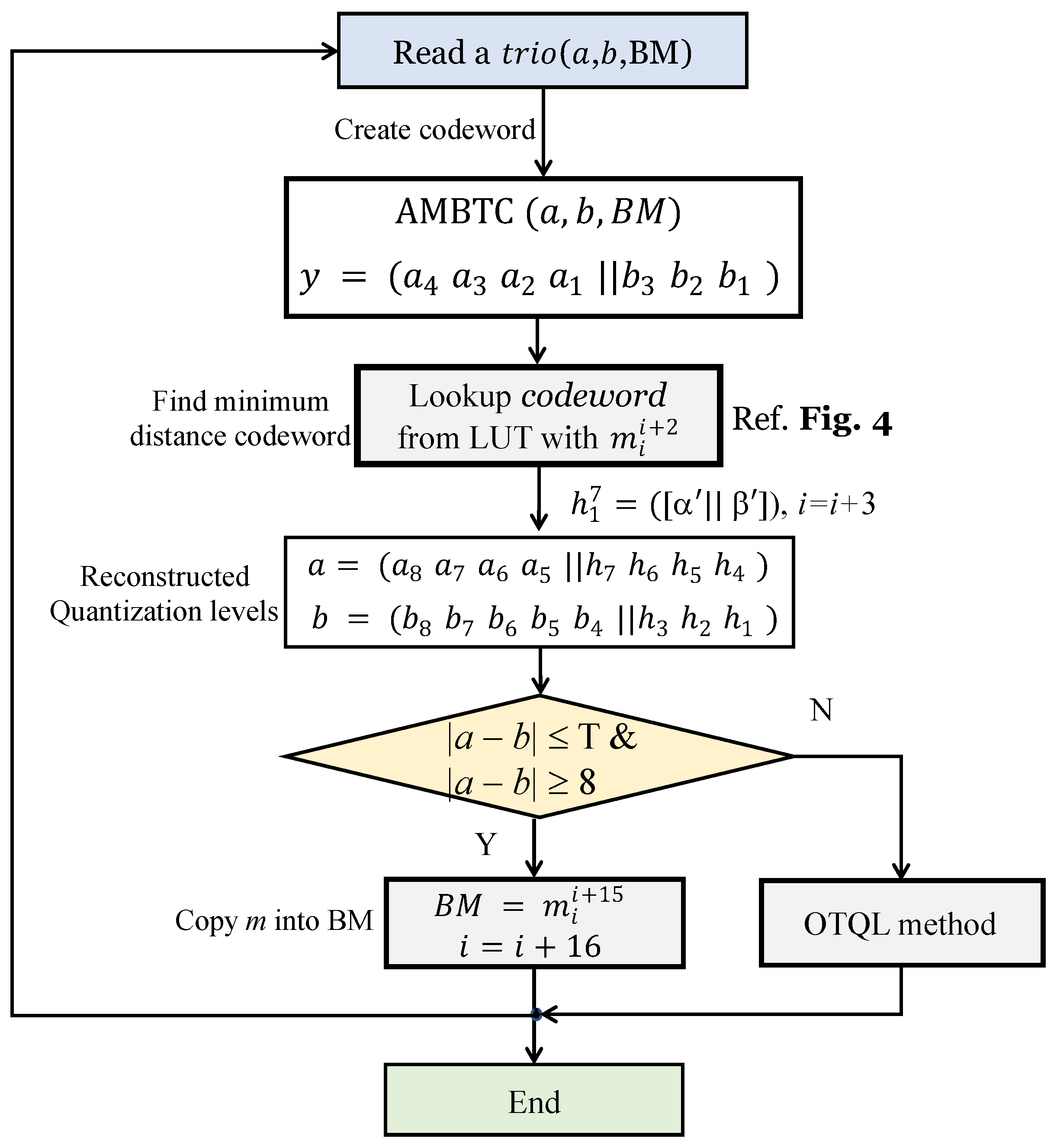
We introduce a way of DH using the Hamming code, DBS, and OTQL based on AMBTC and explain the details of the procedure step-by-step as follows. Additionally, the flowchart of the embedding process is described in Figure 2.
Input: 
Original grayscale image with a size of N × N , threshold T, and secret data M = ( m 1 , m 2 , , m n ) .
Output: 
Stego AMBTC t r i o s .
Step 1:
The original image G is divided into 4 × 4 non-overlapping blocks.
Step 2:
The t r i o ( a , b , B M ) of the AMBTC, i.e., the compressed codes, is obtained according to Equations (1)–(4), where a and b are the low mean and the high mean quantization levels, respectively, and B M is the bitmap.
Step 3:
The quantization levels are a = ( a 8 a 7 a 1 ) and b = ( b 8 b 7 b 1 ) , where a 8 is the Most Significant Bit (MSB) of a and a 1 is the LSB of a. Similarly, b 8 is the MSB of b, and b 1 is the LSB of b. The rearranged seven bit codeword is obtained by:
y = ( a 4 a 3 a 2 a 1 | | b 3 b 2 b 1 )
where the symbol | | denotes concatenation. Note that a 4 and b 1 are the MSB and LSB of the rearranged pixel y, respectively.
Step 4:
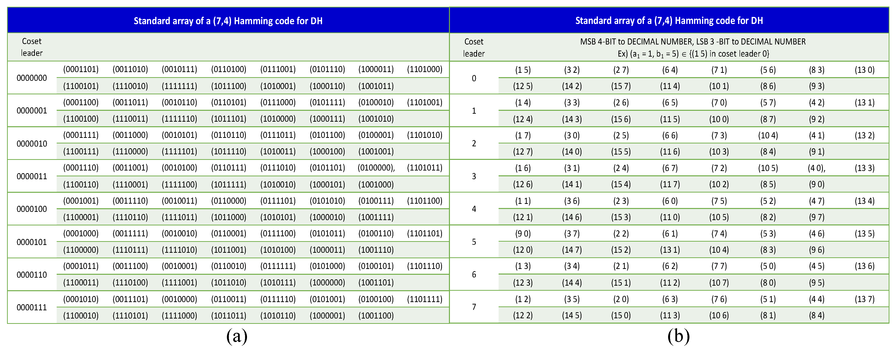
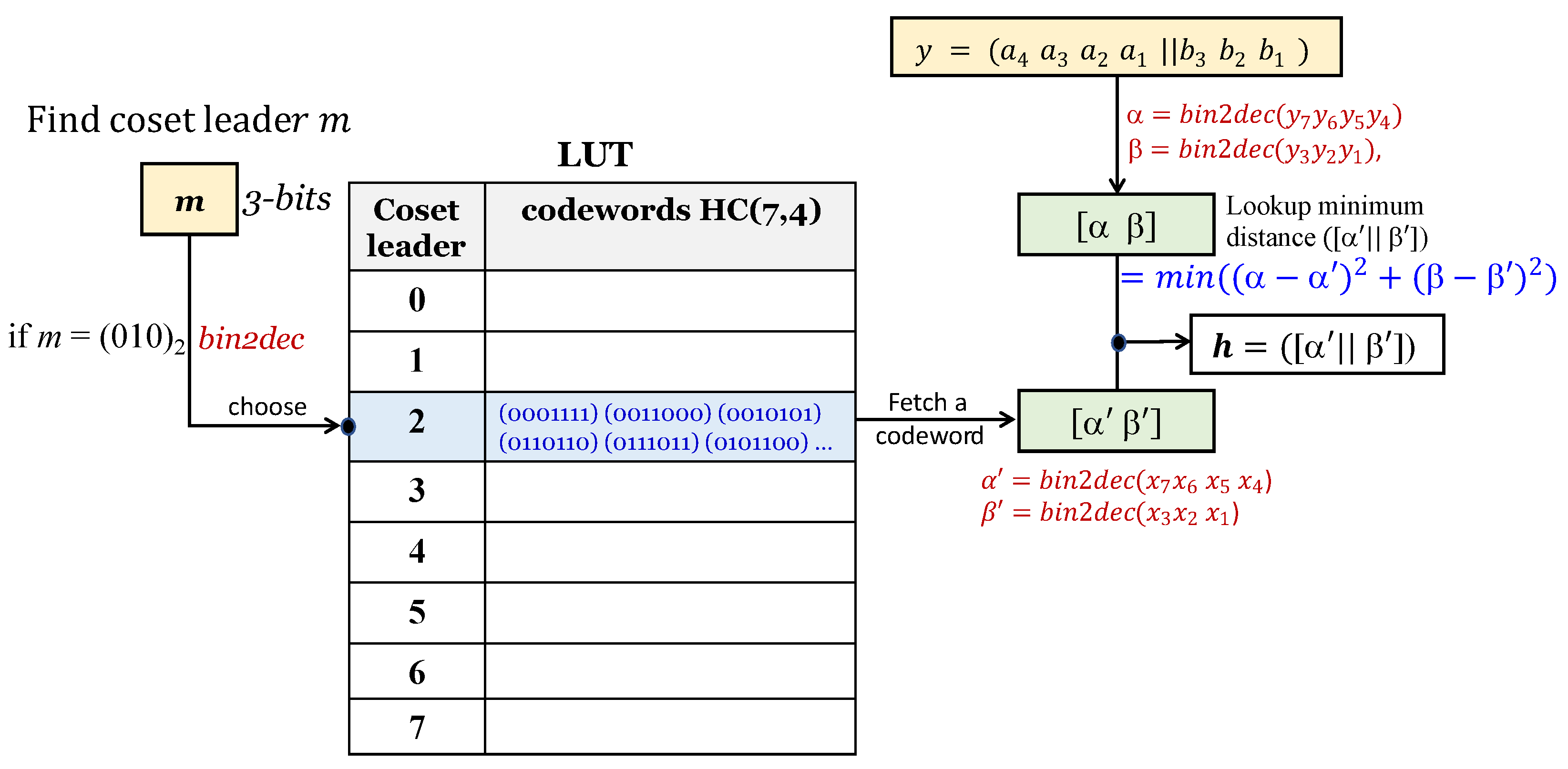
In Figure 3b, the location of the coset leader that matches the decimal number d for m i i + 2 bits is retrieved from the Lookup Table (LUT) using the procedure in Figure 4. Assuming that x i = ( x 7 x 6 x 5 x 4 x 3 x 2 x 1 ) , the codewords corresponding to the retrieved coset reader are converted to ( α β ) . That is, α = b i n 2 d e c ( x 7 x 6 x 5 x 4 ) and β = b i n 2 d e c ( x 3 x 2 x 1 ) . Meanwhile, for codeword y generated in Step 3, α = b i n 2 d e c ( y 7 y 6 y 5 y 4 ) and β = b i n 2 d e c ( y 3 y 2 y 1 ) are converted; that is, y = ( α β ) . The distances for x and y are calculated using Equation (9). After calculating m i n ( ( α α ) 2 + ( β β ) 2 ) for all codewords, the value with the minimum distance among them is obtained. The obtained minimum distance codeword is h = ( α β ) .
ϵ = m i n >( ( α α ) 2 + ( β β ) 2 )
For the codeword h, two quantization levels, a and b, are constructed as follows:
a = ( a 8 a 7 a 6 a 5 | | h 7 h 6 h 5 h 4 ) b = ( b 8 b 7 b 6 b 5 b 4 | | h 3 h 2 h 1 )
Before next step, three is added to the index variable i.
Step 5:
If | a b | T , it may be a smooth block. For the smooth block, we use DBS. The m i i + 15 bits replace the pixels of the BM. Fifteen is added to the index variable i before the next step. If | a b | > T and | a b | 8 , OTQL is launched. If m i i = 1 , transpose the order of two quantization levels, a and b, of the t r i o , otherwise put the t r i o as the original state.
Step 6:
Repeat Steps 2∼5 until all image blocks are processed. Then, the stego AMBTC compressed codes’ t r i o is constructed.

3.2. Extraction Procedure

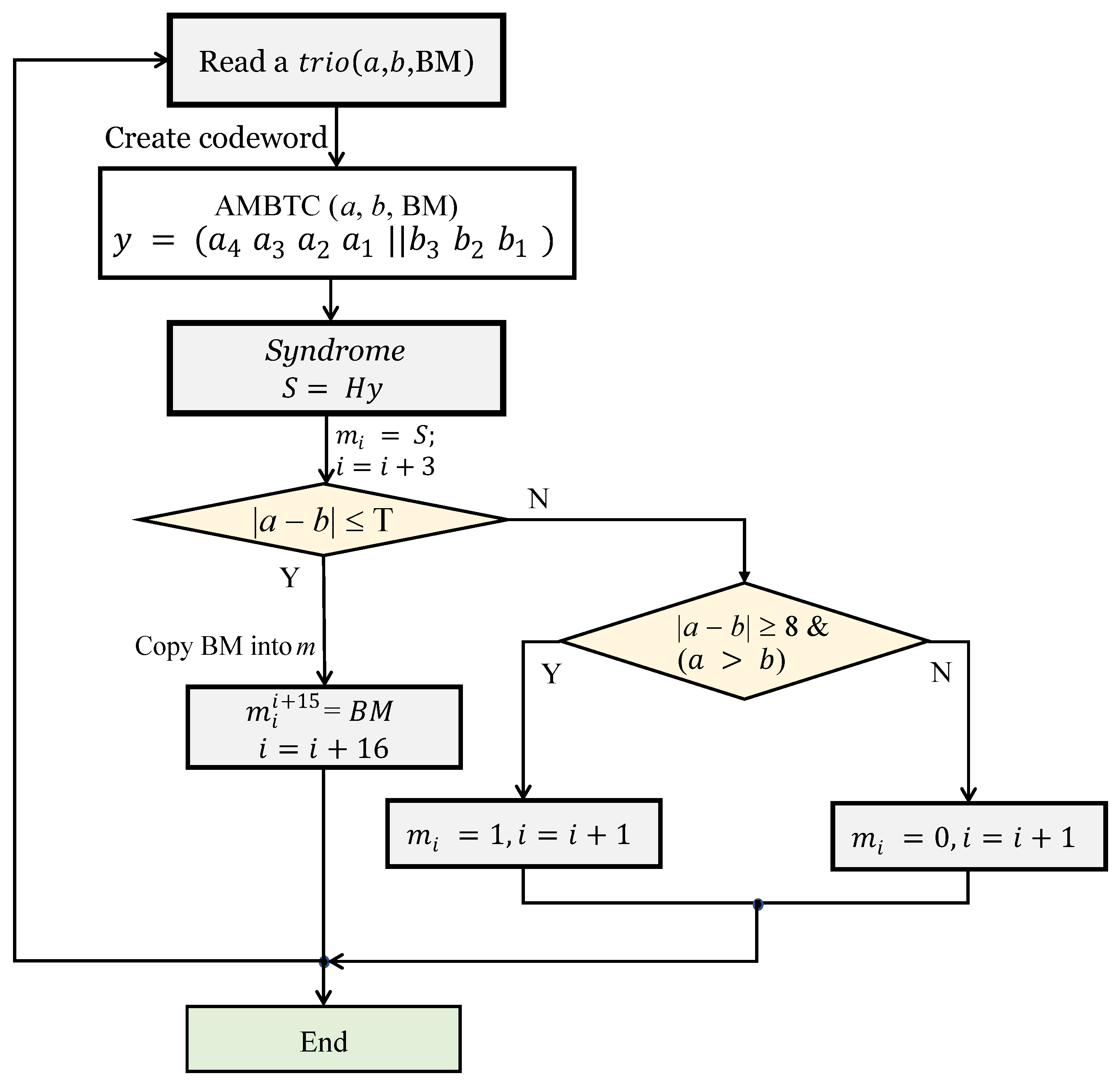
The procedure for extracting the hidden secret bits is shown in Figure 5. The process is explained in detail according to the following procedure.
Input: 
Stego AMBTC compressed codes t r i o s , matrix H = 0 0 0 1 1 1 1 0 1 1 0 0 1 1 1 0 1 0 1 0 1 , and threshold T.
Output: 
Secret data M = ( m 1 , m 2 , , m n ) .
Step 1:
Read one block of t r i o ( a , b , B M ) from a set of t r i o s as a defined order, where the t r i o consists of two quantization levels and one bitmap.
Step 2:
The quantization levels are a = ( a 8 a 7 a 1 ) and b = ( b 8 b 7 b 1 ) , where a 8 is the MSB of a and a 1 is the LSB of a. Similarly, b 8 is the MSB of b and b 1 is the LSB of b. The rearranged seven bit codeword is y = ( a 4 a 3 a 1 a 1 | | b 3 b 2 b 1 ) by Equation (8).
Step 3:
Obtain the syndrome S = y · H T . Then, assign S to m i i + 2 , and add three to i.
Step 4:
If | a b | T , it is a smooth block t r i o . In this case, this means that the hidden bits were embedded in the BM in the form of pixels. Therefore, by assigning the pixels of the BM to m in order, all the values concealed in the BM can be obtained. That is, m i i + 15 = B M 1 16 and i = i + 15 . If | a b | > T and | a b | 8 , one bit is hidden in the t r i o by using the order of two quantization levels. If the order of two quantization levels is t r i o ( b , a , B M ) , this means that m i i = 1 , otherwise m i i = 0 .
Step 5:
Repeat Steps 1 4 until all the t r i o s are completely processed, and the extracted bit sequence constitutes the secret data m.

3.3. Examples

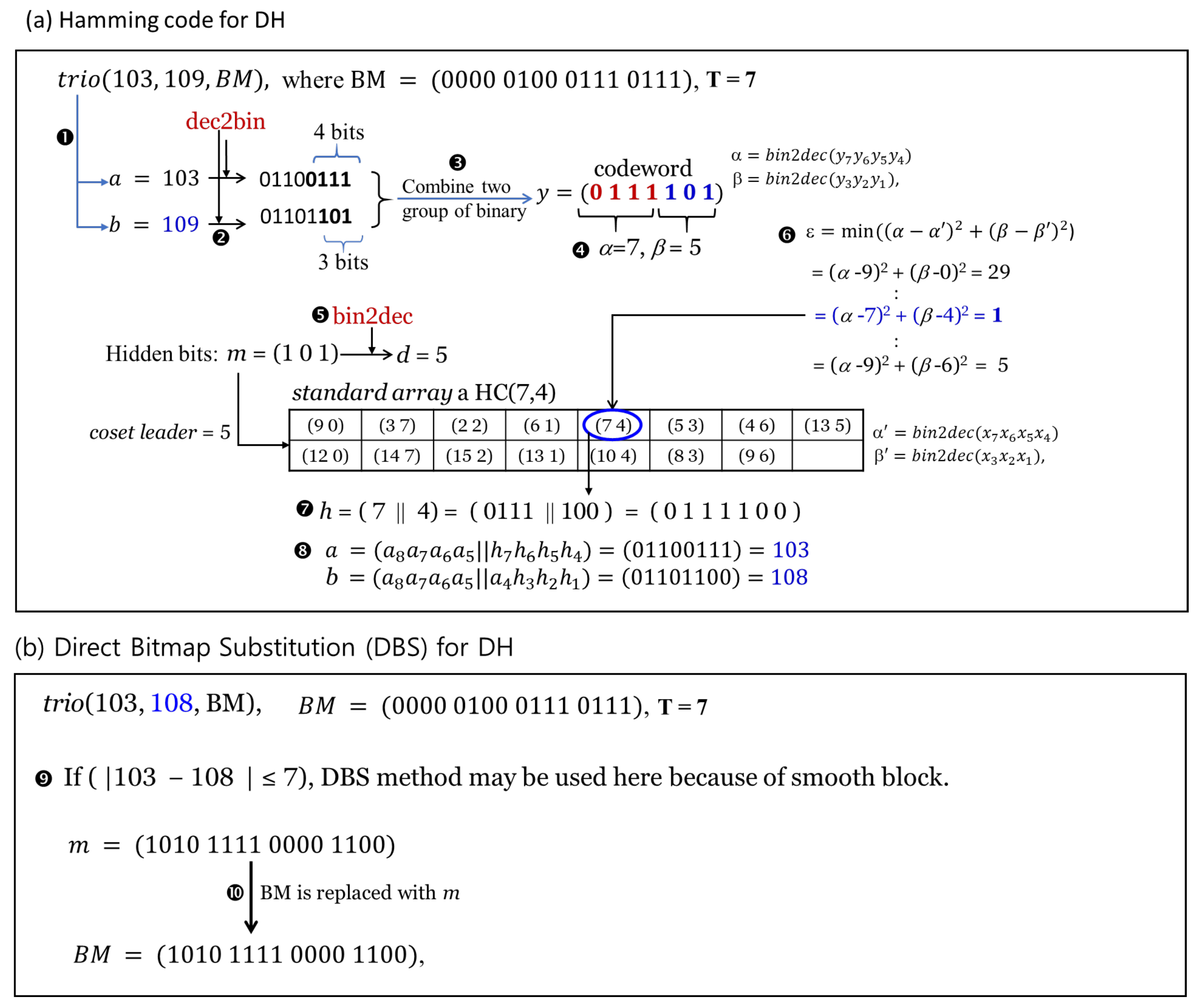
Here, we will show how to minimize the errors in the encoding process through an optimized method rather than the existing method. The detailed procedure of our proposed DH is explained by the process shown in Figure 6 using t r i o ( 103 , 109 , 0000010001110111 ) and secret bits m = ( 1011010111100001100 ) . Since b a = 109 103 = 6 T ( 7 ) , the t r i o is classified as a smooth block. Therefore, in Figure 2, the data concealment process proceeds according to the processing corresponding to the smooth block of the t r i o . From now on, the process shown in Figure 6a will be explained step-by-step.
(1)
The two quantization levels of a given t r i o are assigned to variables a and b and then converted to binary, i.e., a = 103 = 01100111 2 and b = 109 = 01101101 2 .
(2)
For the two converted binary numbers, the four LSB ( a = ( 0110 0111 ̲ 2 ) of a and the three LSB ( b = ( 01101 101 ̲ 2 ) ) of b are extracted.
(3)
To form a codeword, the extracted binary numbers are combined; that is, y = ( 0111 | | 101 ) 2 .
(4)
Calculate y = ( b i n 2 d e c ( 0111 ) b i n 2 d e c ( 101 ) ) = ( 7 5 ) .
(5)
After converting the bit m ( = 101 ) to decimal, the value d = 5 is retrieved from the coset leaders of the standard array of HC (7,4).
(6)
Using Equation (9), the codeword having the minimum distance from the given codeword is retrieved from the table. Here, ( a 7 ̲ ) 2 + ( b 4 ̲ ) 2 = 1 corresponds to the minimum distance.
(7)
The new codeword is h = ( 7 | | 4 ) = ( 0111 | | 100 ) 2 = ( 0111100 ) 2 .
(8)
Two quantization levels embedding three secret bits are recovered by using the codeword h. A new quantization level is obtained by replacing the upper four bits and the lower three bits of h obtained in the process of (7), respectively, with four LSB and three LSB of two quantization levels. That is, the recovered codewords are a = 103 and b = 108 .
In Figure 6b, we explain a way of embedding secret bits into the bitmap.
(1)
First, it is necessary to check whether a given block belongs to a smooth block. That is, if the difference between the absolute values of two given quantization levels is less than the threshold T, it is a smooth block, otherwise it belongs to a complex block. In Figure 6b, the difference between two given quantization levels is less than the defined threshold T, so it belongs to a smooth block.
(2)
Since the block in the given example is a smooth block, sixteen bits are concealed in the bitmap by replacing the 16 bit secret bits (m = (1010 1111 0000 1100)) directly with the bitmap.
To extract secret bits from two quantization levels, we need to construct a codeword using the quantization levels. To construct the codeword, the procedure of Figure 6a is followed. That is, the codeword ( y = 0111100 ) is obtained by extracting four LSB (0111) and three LSB (100) from two quantization levels a ( = 103 ) and b ( = 108 ) and combining them. Here, we obtain the hidden secret bits, m ¯ = ( 101 ) , by using the equation, S = y · H T , to the codeword. The decoding of the secret bits in the BM extracts the hidden bits by moving all pixels in the BM into a variable m ¯ array directly.

4. Experimental Results

In this section, we prove the performance of our proposed scheme by comparing with the existing methods, such as Bai and Chang [30], W Hong [33], and Chuang et al. [28]. As shown in Figure 7, six grayscale images sized 512 × 512 are used for our experiments. In addition, the block size of AMBTC is set to 4 × 4 , and the secret bits are generated by a pseudo-random number generator. Embedding Capacity (EC) and the Peak Signal-to-Noise Ratio (PSNR) are widely used as objective image evaluation indices. Here, EC is used as an indicator for the number of secret bits that can be embedded in a cover pixel. The relatively high PSNR value means that the quality of the stego image is good. The DH capacity is the size of the secret bit that is embedded in the cover image. The quality of the image is measured by the PSNR defined as:
P S N R = 10 l o g 10 255 2 M S E
The Mean-Squared Error (MSE) used in the PSNR denotes the average intensity difference between the stego and reference images.
The lower the MSE value of a stego image, the better the quality of the image. The MSE is calculated using the reference image p and the distorted image p as follows.
M S E = 1 N × N i = 1 N j = 1 N ( p i j p i j ) 2
The error value ϵ = p i j p i j indicates the difference between the original and the distorted pixels. The 255 2 means the allowable pixel intensity in Equation (11). A typical value for the PSNR in a lossy image is from 30 dB to 50 dB for an eight bit depth; the higher the better. Structural SIMilarity (SSIM) [39] estimates whether changes such as image brightness, photo contrast, and other residual errors are identified as structural changes. The SSIM values is limited to a range between zero and one. If the SSIM value is close to one, it means that the stego image is similar to the cover image and of high quality. The equation of SSIM is as follows:
S S I M ( x , y ) = ( 2 μ x μ y + c 1 ) ( 2 σ x y + c 2 ) ( μ x 2 μ y 2 + c 1 ) ( μ x 2 μ y 2 + c 2 )
where μ x , μ y are the mean values of the cover image (x) and stego image (y), σ x , σ y , σ x 2 , σ y 2 , and σ x y are the standard deviation, variances, and covariance of the cover image and stego image, and c 1 , c 2 , c 3 are constant values to avoid the division by zero problem.
The Normalized Cross-Correlation (NCC) has been commonly used as a metric to evaluate the degree of similarity (or dissimilarity) between two compared images. The main advantage of the NCC is that it is less sensitive to linear changes in the amplitude of illumination in the two compared images. Furthermore, the NCC is confined to the range between −1 and one. NCC is calculated by the formula given in Equation (14).
N C C = x = 1 M y = 1 N ( S ( x , y ) × C ( x , y ) ) x = 1 M y = 1 N ( S ( x , y ) ) 2
Table 1 represents the comparison of EC and PSNR between the proposed scheme and existing methods, i.e., Ou and Sun [29], Bai and Chang [30], and W Hong et al. [33]. Specifically, we compare the performance between our scheme and the existing methods using six images when the threshold value T ( = b a ) is 5, 10, and 20. The evaluation of EC and the PSNR based on threshold values is necessary for objectivity and fairness for comparative evaluation of the performance; that is, the data measured under the same threshold value may be evaluated as a more meaningful comparison. One important point for EC and PSNR is that there is a trade-off between the two assessments. That is, if EC is higher, the PSNR is reduced, and vice versa. However, in the case that the proposed method has very good performance, the deviation from the trade-off may not be large. The EC of our proposed method is efficient with respect to the EC as 151,173 bits when T = 5 .
In Table 1, Bai and Chang’s PSNR (=33.0656 dB) is measured as higher than that (=32.6911 dB) of our proposed method. Here, the EC of Bai and Chang [30] is 55,407 bits, and the EC of our method is 151,173 bits. In the end, our proposed method shows the capability to conceal about 95,000 bits more than that of Bai and Chang.
If the threshold T and EC are given for a faithful measurement, the PSNR of our proposed method may be the highest. This is because the size of the hidden bits affects the PSNR. Apparently, a relative good method has high values both for the PSNR and EC. When T = 10 , we can see that our method’s EC (=219,847 bits) is the largest. The method of W Hong [33] and our proposed method both have the same PSNR ( 31.7 dB), which is 0.1 dB lower than that of Ou and Sun’s method [29]. However, in this case as well, when considering the amount of EC, our method outperforms the other two methods.
When T = 20 , the PSNR of the proposed method is higher than the previous two methods (Ou and Sun [29] and W Hong [33]), and the EC of our method has the highest performance. It can be seen from the simulation results in Table 1 that the proposed method has 140,000 bits more than that of Bai and Chang [30] in terms of EC.
Figure 8 shows the performance comparison between our proposed method and the existing methods, where we measured the PSNR while increasing the capacity of the secret bits from 20,000 bits to 310,000 bits in four images ((a) Lena, (b) Boat, (c) Pepper, and (d) Zelda) by using the proposed and existing methods.
We propose a way to improve the performance of Bai and Chang’s method [30], and as shown in Figure 8, it is confirmed that our proposed method is superior to existing methods. On the other hand, our proposed method shows almost the same performance as W Hong’s method [33], but it can be confirmed that the performance of our proposed scheme is slightly better. Ou and Sun’s method [29] is superior to Bai and Chang’s method [20], but the performance is not as high as that of our proposed method.
AMBTC has difficulty hiding enough data, because it is a compressed code, and unlike conventional grayscale images, it is not easy to exploit high embedding capacity by the constraint of compressed pixels. It is difficult to improve the DH performance for images with many complex blocks, and if we exploit many pixels for high data concealment, the image quality may deteriorate.
In Figure 8, we can see that the EC of Bai and Chang’s method [30] is very low. That is because this method can hide only six bits of data while inverting up to two pixels in each bitmap. Thus, there is a limit to embedding enough data in the trio’s bitmaps. Since this method cannot conceal many secret bits for the threshold T of the same condition, it shows a relatively high PSNR. After all, that is why this method is inferior to other methods. If we would like to increase the number of secret bits even at the expense of the PSNR, it is possible to increase the size of the threshold T. However, it may often be the case that the PSNR becomes worse than expected without increasing the number of hidden bits. For example, when T 4 , the three methods except Bai and Chang’s method can hide about 130,000 bits, while the PSNRs are slightly reduced. For such a large amount of data to embed, they exploited the DBS method with respect to B M equally.
Bai and Chang’s method must increase the T value in order to conceal 130,000 bits of data, and as a result, the errors accumulate rapidly. Since Bai and Chang’s method [30] uses up to four LSB for data concealment, the size of the error inevitably increases. Since our proposed method uses up to three LSB and the frequent count of three LSB is also not very high, the negative effect on image quality is less than that of Bai and Chang’s method [30]. In the end, we prove that the proposed method has a better optimization performance than Bai and Chang’s method [30].
Figure 9 shows the evaluation by comparing the histograms of stego images generated from the proposed method and existing methods, i.e., W Hong, Ou and Sun, and Bai and Chang. Here, stego images are generated after concealing 150,000 bits in the cover Lena image by the existing and proposed methods. The pixel value range on the x-axis is [95, 115]. In Figure 9, the curves of our proposed method and the two existing methods (i.e., W Hong and Ou and Sun) are similar, while Bai and Chang’s histogram curve has a larger amplitude than the other methods. The reason is that the maximum EC of Bai and Chang’s method is up to 150,000 bits. In other words, we can see that the quality of the image reaches the lower limit because it exhausts all possible resources. The histogram does not show much difference because our proposed method and the two existing methods keep more than 33 dB in common when concealing 150,000 bits. As shown in Figure 8, as the EC increases, the histogram of the stego image also is far from the histogram of the original cover image.
Table 2 shows an experiment to compare the PSNR and SSIM after concealing the same amount of data (120,000 bits) in the cover image for a more objective performance check and reliable comparison. The SSIM of the proposed method shows the highest value. On the other hand, in the case of the PSNR, W Hong’s method [33] shows a high average. In fact, the PSNR only quantifies the quality of reconstructed or damaged images in relation to the facts. For this reason, we introduce SSIM as a criterion for the secondary evaluation. SSIM evaluates the structure of the image. The SSIM of the reconstructed image for the ground image is always one, and if the value is close to one, you can see that the image quality is excellent. Therefore, we can see that our proposed method is superior to the existing methods in terms of SSIM.
Table 3 shows the MSE and NCC simulation results for the existing and proposed methods for the four images. The average MSE value of the proposed method is lower than those of the three other methods. The MSE value of the Airplane image in our proposed method is slightly higher than those of Ou and Sun [29] and W Hong [33]. However, from the NCC scores, there is no difference, so it is objectively proven that there is no problem with the performance of our proposed method. Furthermore, when the maximum EC of Ou and Sun reaches 270,000 bits, the PSNR drops to 23 dB. On the other hand, our proposed method can maintain the PSNR higher than 30 dB, so the DH performance of our proposed method is useful. Our proposed method can obtain better performance by creating a lookup table to obtain more optimal values than W Hong’s method.
Table 4 shows the comparison of the CPU execution time between the proposed and the existing methods. The computer for the experiment is a YOGA 730, and the CPU processor is Intel(R) Core(TM) i5-8250U CPU 1.6 GHz. The software is MATLAB R2019a. Here, we measure the CPU time to conceal a random number from 20,000 bits to 200,000 bits in the Lena image by using the four methods (i.e., Ou and Sun, W Hong, Bai and Chang, our proposed method). The process of the measurement includes AMBTC compression, data embedding, and AMBTC decompression. The most time-consuming method is that of Bai and Chang, and the least time-consuming method is that of Ou and Sun. The method we propose is faster than Bai and Chang’s, but it is time consuming compared to the other two. However, if we code using the C language, the required time would be less than 1 s.

5. Conclusions

In this paper, we introduced a DH method that applies DBS and optimized HC(7,4) to AMBTC compressed grayscale images. The basic unit of AMBTC is the t r i o , which consists of two quantization levels and one bitmap and is represented by t r i o ( a , b , b i t m a p ) . Therefore, AMBTC is a trioset, and the proposed DH method is applied to each block of an image. The proposed method may have different final performance results depending on the characteristics of each block. Therefore, we divided every block into two groups (smooth blocks and complex blocks) and applied the proposed method. The distinction of whether a block is a smooth block or a complex block is determined by the difference between the two quantization levels of the block. That is, if the difference ( | a b | ) between two quantization levels is smaller than or equal to the threshold T, it is categorized as a smooth block. When hiding data in a complex block with a difference higher than threshold T, the MSE errors increase compared to a smooth block. Therefore, it is important in terms of DH to distinguish the blocks. In other words, the smoother the blocks are, the more they help to maintain the image quality while concealing more data. In this paper, our proposed method achieved the optimized level by HC(7,4) based on the lookup table. As a result, it was shown through experiments that our proposed scheme surpasses the performance of Hong’s method. Experimental results show that the proposed scheme provides a high EC while suppressing the loss of quality of the cover image. In the future, we will devise a method to calculate a more optimal distance when applying HC(7,4) to two quantization levels and conduct research to find a way to minimize data concealment errors.

Author Contributions

Conceptualization, C.-N.Y. and C.K.; methodology, D.S. and C.K.; validation, C.-N.Y. and C.K.; formal analysis, C.-N.Y.; writing, original draft preparation, C.K. and L.L.; funding acquisition, D.-K.S., C.-N.Y., C.K., and L.L. All authors read and agreed to the published version of the manuscript.

Funding

This work was supported by the National Natural Science Foundation of China (61866028), the Key Program Project of Research and Development (Jiangxi Provincial Department of Science and Technology) (20171ACE50024), the Foundation of China Scholarship Council (CSC201908360075), and the Open Foundation of Key Laboratory of Jiangxi Province for Image Processing and Pattern Recognition (ET201680245, TX201604002). This research was supported in part by the Ministry of Science and Technology (MOST), under grants MOST 108-2221-E-259-009-MY2 and 109-2221-E-259-010. This research was supported by the Basic Science Research Program through the National Research Foundation of Korea (NRF) funded by 2015R1D1A1A01059253 and 2018R1D1A1B07047395 and was supported under the framework of the international cooperation program managed by NRF (2016K2A9A2A05005255).

Conflicts of Interest

The authors declare no conflict of interest.

References

  1. Chang, C.C.; Li, C.T.; Shi, Y.Q. Privacy-aware reversible watermarking in cloud computing environments. IEEE Access 2018, 6, 70720–70733. [Google Scholar] [CrossRef]
  2. Byun, S.W.; Son, H.S.; Lee, S.P. Fast and robust watermarking method based on DCT specific location. IEEE Access 2019, 7, 100706–100718. [Google Scholar] [CrossRef]
  3. Kim, C.; Yang, C.N. Watermark with DSA signature using predictive coding. Multimed. Tools Appl. 2015, 74, 5189–5203. [Google Scholar] [CrossRef] [Green Version]
  4. Kim, H.J.; Kim, C.; Choi, Y.; Wang, S.; Zhang, X. Improved modification direction methods. Comput. Math. Appl. 2010, 60, 319–325. [Google Scholar] [CrossRef] [Green Version]
  5. Kim, C. Data hiding by an improved exploiting modification direction, Multimed. Tools Appl. 2010, 69, 569–584. [Google Scholar] [CrossRef]
  6. Petitcolas, F.A.P.; Anderson, R.J.; Kuhn, M.G. Information hiding—A survey. Proc. IEEE 1999, 87, 1062–1078. [Google Scholar] [CrossRef] [Green Version]
  7. Kim, C.; Shin, D.; Yang, C.N.; Chen, Y.C.; Wu, S.Y. Data hiding using sequential hamming + k with m overlapped pixels. KSII Trans. Internet Inf. 2019, 13, 6159–6174. [Google Scholar]
  8. Mielikainen, J. LSB matching revisited. IEEE Signal Proc. Lett. 2006, 13, 285–287. [Google Scholar] [CrossRef]
  9. Chan, C.K.; Cheng, L.M. Hiding data in images by simple LSB substitution. Pattern Recognit. 2004, 37, 469–474. [Google Scholar] [CrossRef]
  10. Kim, C.; Shin, D.; Kim, B.G.; Yang, C.N. Secure medical images based on data hiding using a hybrid scheme with the Hamming code. J. Real-Time Image Process. 2018, 14, 115–126. [Google Scholar] [CrossRef]
  11. Tian, J. Reversible data embedding using a difference expansion. IEEE Trans. Circuits Syst. Video Technol. 2003, 13, 890–896. [Google Scholar] [CrossRef] [Green Version]
  12. Hu, Y.; Lee, H.-K.; Li, J. DE-based reversible data hiding with improved overflow location map. IEEE Trans. Circuits Syst. Video Technol. 2008, 19, 250–260. [Google Scholar]
  13. Celik, M.U.; Sharma, G.; Tekalp, A.M.; Saber, E. Lossless generalized-LSB data embedding. IEEE Trans. Image Process. 2005, 14, 253–266. [Google Scholar] [CrossRef] [PubMed]
  14. Ni, Z.; Shi, Y.-Q.; Ansari, N.; Su, W. Reversible data hiding. IEEE Trans. Circuits Syst. Video Technol. 2006, 16, 354–362. [Google Scholar]
  15. Kim, C.; Baek, J.; Fisher, P.S. Lossless Data Hiding for Binary Document Images Using n-Pairs Pattern. In Proceedings of the Information Security and Cryptology—ICISC 2014, Lecture Notes in Computer Science (LNCS), Seoul, Korea, 3–5 December 2014; Volume 8949, pp. 317–327. [Google Scholar]
  16. Hong, W.; Chen, T.-S.; Chang, Y.-P.; Shiu, C.W. A high capacity reversible data hiding scheme using orthogonal projection and prediction error modification. Signal Process. 2010, 90, 2911–2922. [Google Scholar] [CrossRef]
  17. Carpentieri, B.; Castiglione, A.; Santis, A.D.; Palmieri, F.; Pizzolante, R. One-pass lossless data hiding and compression of remote sensing data. Future Gener. Comput. Syst. 2019, 90, 222–239. [Google Scholar] [CrossRef]
  18. Zhang, X. Reversible data hiding in encrypted image. IEEE Signal Process. Lett. 2011, 18, 255–258. [Google Scholar] [CrossRef]
  19. Puteaux, P.; Puech, W. An efficient MSB prediction-based method for high-ca- pacity reversible data hiding in encrypted images. IEEE Trans. Inf. Forensics Secur. 2018, 13, 1670–1681. [Google Scholar] [CrossRef] [Green Version]
  20. Zhang, F.; Lu, W.; Liu, H.; Yeung, Y.; Xue, Y. Reversible data hiding in binary images based on image magnification. Multimed. Tools Appl. 2019, 78, 21891–21915. [Google Scholar] [CrossRef]
  21. Leng, L.; Li, M.; Kim, C.; Bi, X. Dual-source discrimination power analysis for multi-instance contactless palmprint recognition. Multimed. Tools Appl. 2017, 76, 333–354. [Google Scholar] [CrossRef]
  22. Leng, L.; Zhang, J.S.; Khan, M.K.; Chen, X.; Alghathbar, K. Dynamic weighted discrimination power analysis: A novel approach for face and palmprint recognition in DCT domain. Int. J. Phys. Sci. 2010, 5, 2543–2554. [Google Scholar]
  23. Deeba, F.; Kun, S.; Dharejo, F.A.; Zhou, Y. Wavelet-Based Enhanced Medical Image Super Resolution. IEEE Access 2020, 8, 37035–37044. [Google Scholar] [CrossRef]
  24. Delp, E.; Mitchell, O. Image compression using block truncation coding. IEEE Trans. Commun. 1979, 27, 1335–1342. [Google Scholar] [CrossRef]
  25. Lema, M.D.; Mitchell, O.R. Absolute moment block truncation coding and its application to color images. IEEE Trans. Commun. 1984, COM-32, 1148–1157. [Google Scholar] [CrossRef]
  26. Kumar, R.; Singh, S.; Jung, K.H. Human visual system based enhanced AMBTC for color image compression using interpolation. In Proceedings of the 2019 6th International Conference on Signal Processing and Integrated Networks (SPIN), Noida, India, 7–8 March 2019; Volume 385, pp. 903–907. [Google Scholar]
  27. Hong, W.; Chen, T.S.; Shiu, C.W. Lossless steganography for AMBTC compressed images. In Proceedings of the 2008 Congress on Image and Signal Processing, Sanya, China, 27–30 May 2008; pp. 13–17. [Google Scholar]
  28. Chuang, J.C.; Chang, C.C. Using a simple and fast image compression algorithm to hide secret information. Int. J. Comput. Appl. 2006, 28, 329–333. [Google Scholar]
  29. Ou, D.; Sun, W. High payload image steganography with minimum distortion based on absolute moment block truncation coding. Multimed. Tools Appl. 2015, 74, 9117–9139. [Google Scholar] [CrossRef]
  30. Bai, J.; Chang, C.C. High payload steganographic scheme for compressed images with Hamming code. Int. J. Netw. Secur. 2016, 18, 1122–1129. [Google Scholar]
  31. Kumar, R.; Kim, D.S.; Jung, K.H. Enhanced AMBTC based data hiding method using hamming distance and pixel value differencing. J. Inf. Secur. Appl. 2019, 47, 94–103. [Google Scholar] [CrossRef]
  32. Chen, J.; Hong, W.; Chen, T.S.; Shiu, C.W. Steganography for BTC compressed images using no distortion technique. Imaging Sci. J. 2013, 58, 177–185. [Google Scholar] [CrossRef]
  33. Hong, W. Efficient data hiding based on block truncation coding using pixel pair matching technique. Symmetry 2018, 10, 36. [Google Scholar] [CrossRef] [Green Version]
  34. Hong, W.; Chen, T.S. A novel data embedding method using adaptive pixel pair matching. IEEE Trans. Inf. Forensics Secur. 2012, 7, 176–184. [Google Scholar] [CrossRef]
  35. Huang, Y.H.; Chang, C.C.; Chen, Y.H. Hybrid secret hiding schemes based on absolute moment block truncation coding. Multimed. Tools Appl. 2017, 76, 6159–6174. [Google Scholar] [CrossRef]
  36. Chen, Y.Y.; Chi, K.Y. Cloud image watermarking: High quality data hiding, and blind decoding scheme based on block truncation coding. Multimed. Syst. 2019, 25, 551–563. [Google Scholar] [CrossRef]
  37. Malik, A.; Sikka, G.; Verma, H.K. An AMBTC compression-based data hiding scheme using pixel value adjusting strategy. Multidimens. Syst. Signal Process. 2018, 29, 1801–1818. [Google Scholar] [CrossRef]
  38. Lin, J.; Weng, S.; Zhang, T.; Ou, B.; Chang, C.C. Two-Layer Reversible Data Hiding Based on AMBTC Image With (7, 4) Hamming Code. IEEE Access 2019, 8, 21534–21548. [Google Scholar] [CrossRef]
  39. Sampat, M.P.; Wang, Z.; Gupta, S.; Bovik, A.C.; Markey, M.K. Complex wavelet structural similarity: A new image similarity index. IEEE Trans. Image Process. 2009, 18, 2385–2401. [Google Scholar] [CrossRef]
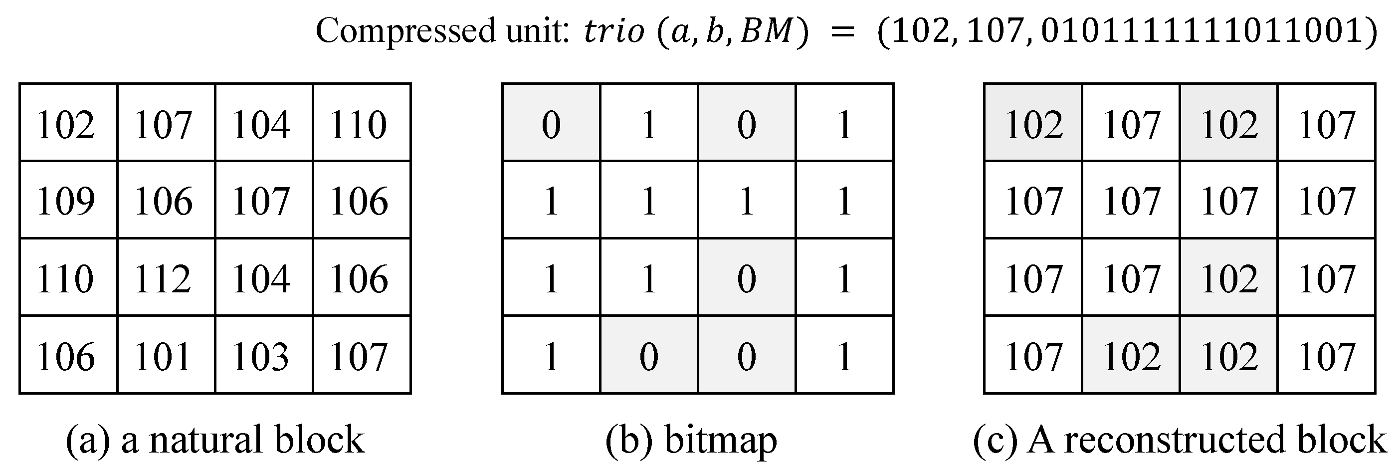
Figure 1. An example of AMBTC: (a) a natural block; (b) a bitmap block; (c) a reconstructed block. BM, Bitmap.
Applsci 10 05336 g001
Figure 2. The flowchart of the data embedding process. OTQL, Order of Two Quantization Level.
Applsci 10 05336 g002
Figure 3. Standard array of HC(7,4) for Data Hiding (DH): (a) binary presentation and (b) decimal presentation.
Applsci 10 05336 g003
Figure 4. The flowchart of the lookup codeword with m. HC, Hamming Code.
Applsci 10 05336 g004
Figure 5. The flowchart of the extracting procedure.
Applsci 10 05336 g005
Figure 6. Illustration of data embedding.
Applsci 10 05336 g006
Figure 7. Test images: (af) 512 × 512 .
Applsci 10 05336 g007
Figure 8. Performance comparisons of the proposed method and other related methods (i.e., Ou and Sun, Bai and Chang, Hong) based on four images: (a) Lena, (b) Boat, (c) Pepper, and (d) Zelda.
Applsci 10 05336 g008
Figure 9. Compared histograms among the proposed method and other related methods with the Lena image when the number of hidden bits is 150,000.
Applsci 10 05336 g009
Table 1. PSNR and Embedding Capacity (EC) according to different thresholds T.
ImagesTOu and Sun [29]Bai and Chang’s [30]W Hong [33]The Proposed
EC (bits)PSNR (dB)EC (bits)PSNR (dB)EC (bits)PSNR (dB)EC (bits)PSNR (dB)
Boats5129,24931.350664,01131.2928149,36831.3203166,17631.2846
Goldhill53,87332.702821,29132.707673,40832.6373100,85331.4917
Airplane154,54531.740578,47731.6604175,20331.7181187,26831.2018
Lena135,08933.192967,40033.1760155,88933.1454168,49833.1059
Peppers100,97733.625348,16433.6888121,07233.5682138,71433.4999
Zelda109,58535.743853,09635.8680128,34635.6618145,52635.5624
Average113,88633.059355,40733.0656133,88133.0085151,17332.6911
ImagesTOu and Sun [29]Bai and Chang’s [30]W Hong [33]The Proposed
EC (bits)PSNR (dB)EC (bits)PSNR (dB)EC (bits)PSNR (dB)EC (bits)PSNR (dB)
Boats10160,91331.020482,64431.1508186,33030.9774201,27230.9316
Goldhill127,40931.684264,72132.2382150,34931.6372169,66730.7147
Airplane194,89731.3173102,01831.4875221,82431.2796232,68230.8072
Lena193,24932.3724101,53032.7961220,20532.3277231,07732.2792
Peppers200,36932.2246106,35732.9962227,28732.1842236,65732.1617
Zelda212,75333.6013113,38034.7771240,48333.5452247,72733.5333
Average164,79931.807585,10832.5743190,17031.7623219,84731.7379
ImagesTOu and Sun [29]Bai and Chang’s [30]W Hong [33]The Proposed
EC (bits)PSNR (dB)EC (bits)PSNR (dB)EC (bits)PSNR (dB)EC (bits)PSNR (dB)
Boats20205,80929.5664110,43330.7138233,70929.5557243,12229.5228
Goldhill212,19329.1224117,28631.2597240,23129.1121249,39228.5724
Airplane226,97730.1906122,03731.1269256,11030.1792262,80229.8300
Lena233,69730.7508126,66732.2383264,36630.7356269,43230.7074
Peppers240,97730.691131,51432.4373271,13230.6750276,07730.6495
Zelda253,84131.5579138,90433.9124284,86631.5299288,52731.4777
Average221,12829.9278124,47431.9481250,20729.9158264,89230.1266
Table 2. Performance comparison of the PSNR and SSIM among the proposed and previous schemes (using 120,000 bits).
ImagesOu and Sun [29]Bai and Chang [30]W Hong [33]The Proposed
PSNRSSIMPSNRSSIMPSNRSSIMPSNRSSIM
Boats31.35060.643330.38230.667531.38460.682831.41580.7298
Goldhill31.74990.694231.17790.734532.22030.727931.41580.7642
Airplane31.72820.661431.17540.652631.90340.704231.37370.7305
Lena33.23620.661432.42310.687033.35400.709433.40900.7566
Peppers33.36360.655632.73890.696633.39050.708133.58220.7316
Zelda35.40410.693634.54420.717735.78390.733535.94420.7778
Average32.80540.668332.07360.694333.00610.711032.85680.7484
Table 3. Performance comparison of the MSE and Normalized Cross-Correlation (NCC) between the proposed and previous schemes (using 150,000 bits).
ImagesOu and Sun [29]Bai and Chang [30]W Hong [33]The Proposed
MSENCMSENCMSENCMSENC
Boats49.97950.994697.28980.993251.01120.994547.68100.9950
Goldhill50.24340.993970.22920.993453.17140.993852.01150.9940
Airplane43.49230.996088.1570.995244.22370.996048.14000.9961
Lena32.30980.995457.54530.994833.36440.995331.32580.9957
Peppers32.31990.995555.06790.994834.03080.994330.41840.9958
Zelda21.17710.994332.32150.993821.49660.994318.09910.9948
Average38.25370.994366.76850.994239.54970.994937.94600.9952
Table 4. Comparing the CPU time between the proposed and the existing methods (measurement: seconds).
MethodsHidden Bits
20,00050,00070,00090,000100,000120,000150,000170,000190,000200,000
Ou and Sun1.45311.53131.60941.65631.71881.79691.82811.90631.92191.9531
W Hong1.46881.59381.64061.78131.82811.85941.8751.90631.95312.0313
Bai and Chang2.46883.73445.255.96886.56257.35948.4219---
The proposed1.68751.82812.1252.26562.56252.85943.15633.53133.59383.6094