1. Introduction
Thick coal seams account for around 45% of total coal reserves in China [
1]. The longwall top coal caving (LTCC) method is the most widely used method for extracting thick or ultrathick coal seams in China [
2]. The strata movement law due to extraction of a longwall panel is of great significance both in terms of environment and ground control. With the development of mechanization and intelligence of coal mines, increasing output of coal production due to high-efficiency and intense mining activity is inevitable [
3,
4,
5,
6]. The accurate prediction and monitoring of strata movement is increasingly needed to avoid violent dynamic disasters due to high-ground pressure induced by coal extraction [
7,
8].
Over the decades, a number of studies were conducted and theories proposed regarding ground control in mining. Shi and Goodman [
9,
10] proposed block theory that copes with geometric facts of intersecting discontinuities penetrating a three-dimensional solid, which was then widely adopted in mining and rock engineering. On that basis, Feng et al. [
11] developed a face-contacted block structure theory. Song et al. [
12] developed pressure block theory based on which practical mine pressure control theory was proposed. Qian et al. [
13] proposed key strata theory; they believe that the competent strata that are thick or of high strength dictate the overall movement of the strata between or above them. On the other hand, based on block theory and for different geological conditions, scientists carried out varied ground control investigations against various geological settings or mining conditions.
Zhang et al. [
14] presented a case study of ground response of a longwall gob-side entry in mining of a 17 m-thick coal seam. They found that high stress is closely related to mining of an ultrathick coal seam; 110 m ahead of the longwall face it is dramatically influenced with the most serious impact at 50–60 m ahead of the face. In this study, mainly field observation was used. Xin et al. [
15] investigated roof movement during extraction of a top coal of an inclined coal seam; it was demonstrated through numerical modeling and field observation of working resistance of shields that fracturing starts from the middle–upper roof, then extends upwards. Zhang et al. [
16] studied the coal drawing and flowing behavior in mining of a thick steep coal seam using LTCC by physical and numerical modeling. Song et al. [
17] conducted research on face stability in winning coal of a thick coal seam using the 2-D finite element numerical modeling method. Li et al. [
18] presented a case study of a burst control measure by employing a so-called stagger layout of longwall panel; with support of field a microseismic monitoring data, it showed that this layout can effectively avoid stress concentration on the gob side entry as protective structure is around it.
Salamon [
19] presented a mechanism of caving in longwall mining. Corkum and Board [
20] conducted a numerical modeling study of a longwall mining layout in mining trona in a mine in Wyoming. Shabanimashcool and Li [
21] carried out a numerical modeling study of a longwall coal mine and analyzed the stability of the gate roads. Yavuz [
22] studied the stress resume law in the longwall gob by theoretical analysis and simple numerical modeling. He obtained the cover pressure re-establishment distance theoretically and validated it by numerical modeling. Through physical and numerical modeling approaches, Zhang [
23] studied the ground control measures in extracting an ultrathick coal seam in Xiegou Coal Mine by using split-level gob-side entry technology. Using image processing, Cheng et al. [
24] presented a case study of the spatial–temporal evolution of a mining-induced fracture field in the Shaqu Coal Mine in China. Wang et al. [
25] theoretically and numerically analyzed fracture failure within the roof of a hard and thick sandstone, and gas emission under its controlling effect in the extraction of an underground ultrathick coal seam. Xu et al. [
26] investigated apparent depth effects of dynamic failure of hard, thick roof strata on the underlying coal mass through numerical modeling and field measurement. Wang et al. [
27] built a structural model, and analyzed rock burst occurrence during mining of an especially thick coal seam with a complex combination of different lithology of rock parting, soft coal, and hard coal.
These studies give a strong basis for evaluating and predicting strata movement in longwall top coal caving. However, they used only one or two methods to reach conclusions, which are neither thorough nor comprehensive. In addition, strata movement is a black box problem because it cannot be observed explicitly. Additional more accurate and reliable methods are needed to meet the demand of ground control in mining. Therefore, this paper presents a comprehensive study of strata movement behavior in mining a longwall top coal caving panel of a composite coal seam with partings. This study uses physical modeling with the high resolution digital image correlation method (DICM), universal distinct element code (UDEC) numerical modeling, and field measurement employing high-pressure water injection method (HWJM). It is hoped that the results can provide some insights into ground control in longwall top coal caving mining.
3. Methods and Materials
In this study, physical modeling, numerical modeling, and field measurement were used.
3.1. Physical Simulation (or Modeling)
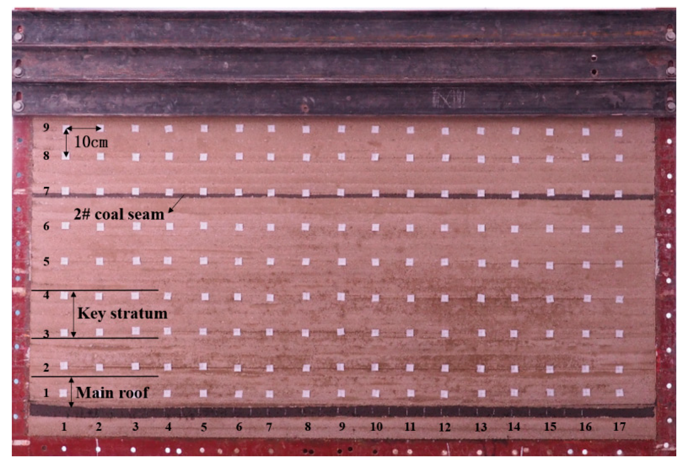
A physical model was built according to the geological and mining conditions. The dimensions of the frame of the model were 1800 × 160 × 1300 mm. The modeled strata were about 150 m thick. The geometric scaling constant was 150:1, constant of density similarity (the ratio of prototype to the model) was 1.6:1, constant of strength similarity was 240:1, and constant of time similarity was 12.2:1. The total number of strata was 17. The floor strata were 9 m thick, the coal seam was 9 m thick, and the overburden strata were 136.5 m thick. The properties of the strata are shown in
Table 1. The model materials consisted of aggregate (sand), cement materials (lime and plaster), and water. The detailed information about each stratum in the model and usages of materials used for constructing the physical model are given in
Table 2. The constructed model is shown in
Figure 3. Nine measuring lines were embedded in the model to monitor the movement of strata. The average vertical distance between two adjacent measuring lines was 10 cm. There were 17 measuring points on each line. The average horizontal interval between points was 10 cm, too. In total, 153 measuring points were distributed within the model.
The digital image correlation method (DICM) was utilized to measure the strata movement. It is an optical method that is widely applied in many areas of science and engineering, which uses tracking and image registration techniques for accurate 2D and 3D measurements of changes in images. It is widely adapted to measure displacement, deformation, strain, etc. [
28,
29]. The images before any excavation were set as datum images; deformed images were then compared with the datum images to get deformation, displacement, or strain data. In order to obtain data that are of high accuracy, a high definition camera and DICM analysis software were combined.
3.2. Numerical Modeling
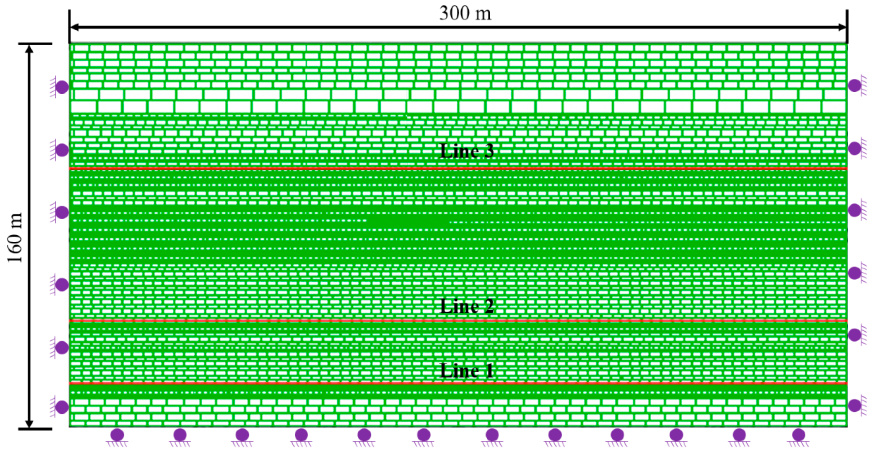
Numerical modeling software, UDEC, i.e., universal distinct element code, was used for studying strata movement. The dimensions of the model were X × Y = 300 × 160 m, the X axis direction was the strike direction, and the Y axis direction was vertical to the bedding planes. All vertical boundaries were restrained horizontally while the bottom boundary was restrained vertically. The mesh size was small for some key strata, such as the coal seam and immediate roof.
Only 27 roof strata were constructed, the other 150 m of overburden was simulated by applying 4 MPa vertical loading on the top of the model. Fifty meters of coal was left on the two sides of the model in order to eliminate the boundary effect. The model is shown in
Figure 4.
The Mohr–Colomb constitutive model was adopted for the failure criterion. According to the data provided by geological department of the mine, the physical and mechanical properties of the strata are presented in
Table 3. The in situ stress measurement results provided by the department indicated that a premining stress with an approximate ratio of horizontal to vertical stresses (K) of value 1 both along and across the panels.
Three measuring lines were laid out to collect strata movement data. Line 1 was located within the main roof, line 2 lay 30 m above the coal seam, and line 3 was situated 88 m above the coal seam.
Simulation steps were to first run the model to reach stress equilibrium before mining, and then extract the coal seam from left to right, step by step. For each step, 5 m of coal web was extracted. Roof movement, deformation, and cave-in were recorded.
Please note that the shields that have little influence on development of the strata movement were not simulated in this numerical modeling study.
3.3. Field Observation
In order to investigate the development of the caved zone and fractured zone in the field, the high-pressure water injection method (HWJM) was employed [
30,
31,
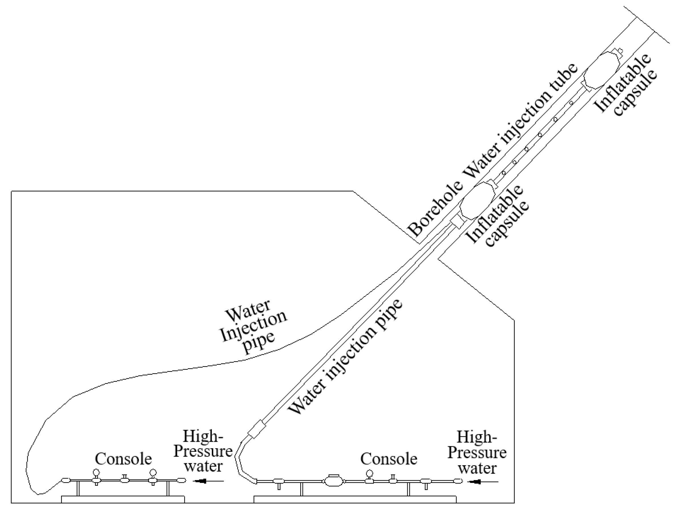
32]. The principle is that by injecting high-pressure water into the surrounding rock, the water losses (or seepages) at different sections (but pressures are the same) of the borehole are different, as shown in
Figure 5. Then the data from along the entire borehole can be plotted. It is obvious that the water losses within the caved zone, the fractured zone, and intact zone must be different. In the intact zone, the water loss must be little. In the fractured zone, the water loss is expected to be much higher than that in the intact zone. In the caved zone, the water loss must be the largest. Therefore, the water loss reflects the degree of fracturing in the surrounding rock, which can define the boundaries of the caved zone and fractured zone.
For this case study mine, underground boreholes were drilled upward into the caved zone and fractured zone. Compared to surface boreholes, underground boreholes are of less cost. The key component of the apparatus is shown in
Figure 6. The entire injection system is shown in
Figure 7. The system consists of three parts: inflatable capsules, tubes or pipes, and consoles.
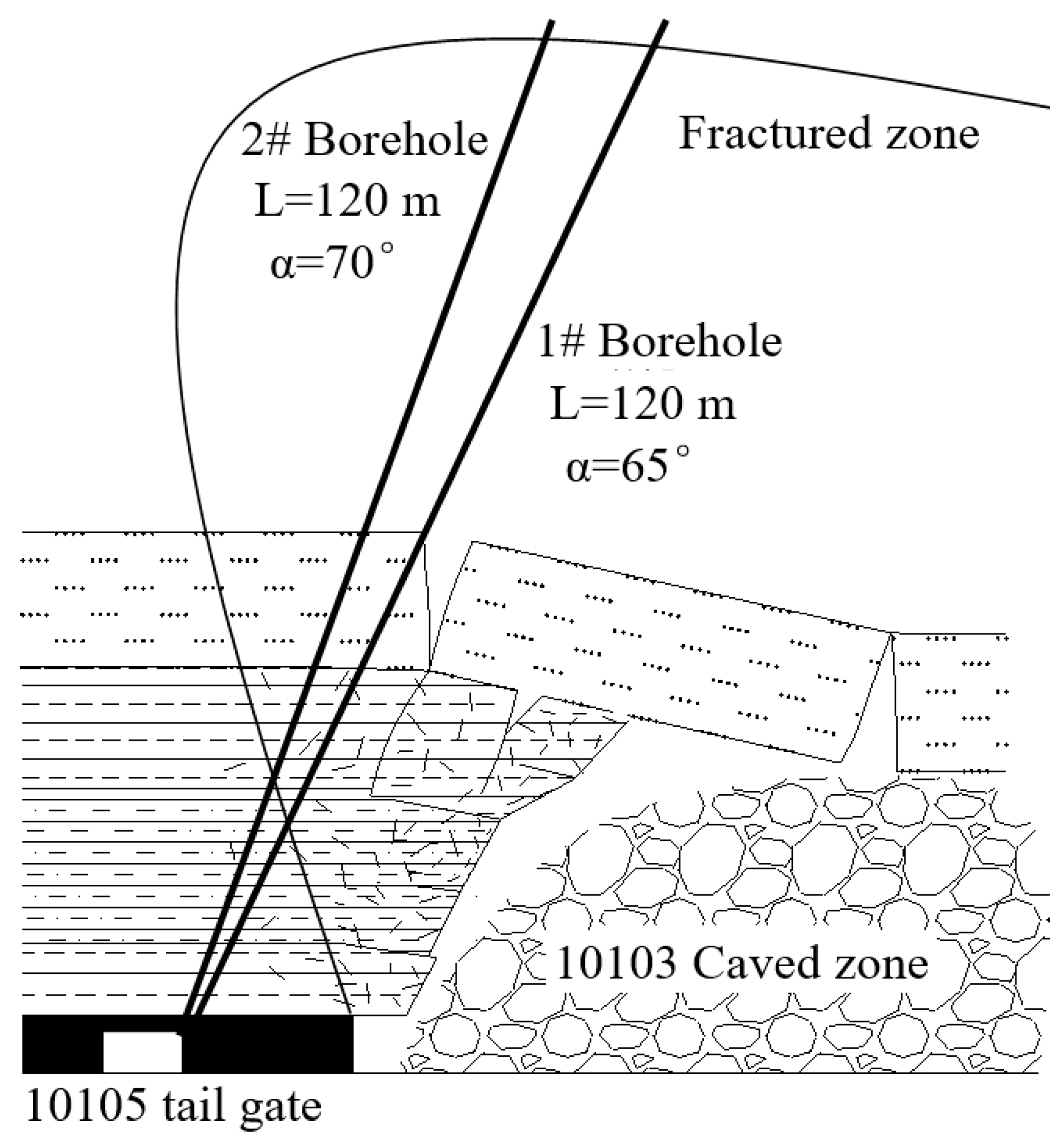
The borehole layout plan is shown in
Figure 8. Two boreholes were drilled upwards from the 10,105 tail gate. The lengths of the two boreholes were both 120 m, the diameters were 75 mm, and the inclinations were 65° and 70°. The detailed information about the two boreholes is presented in
Table 4.
4. Results
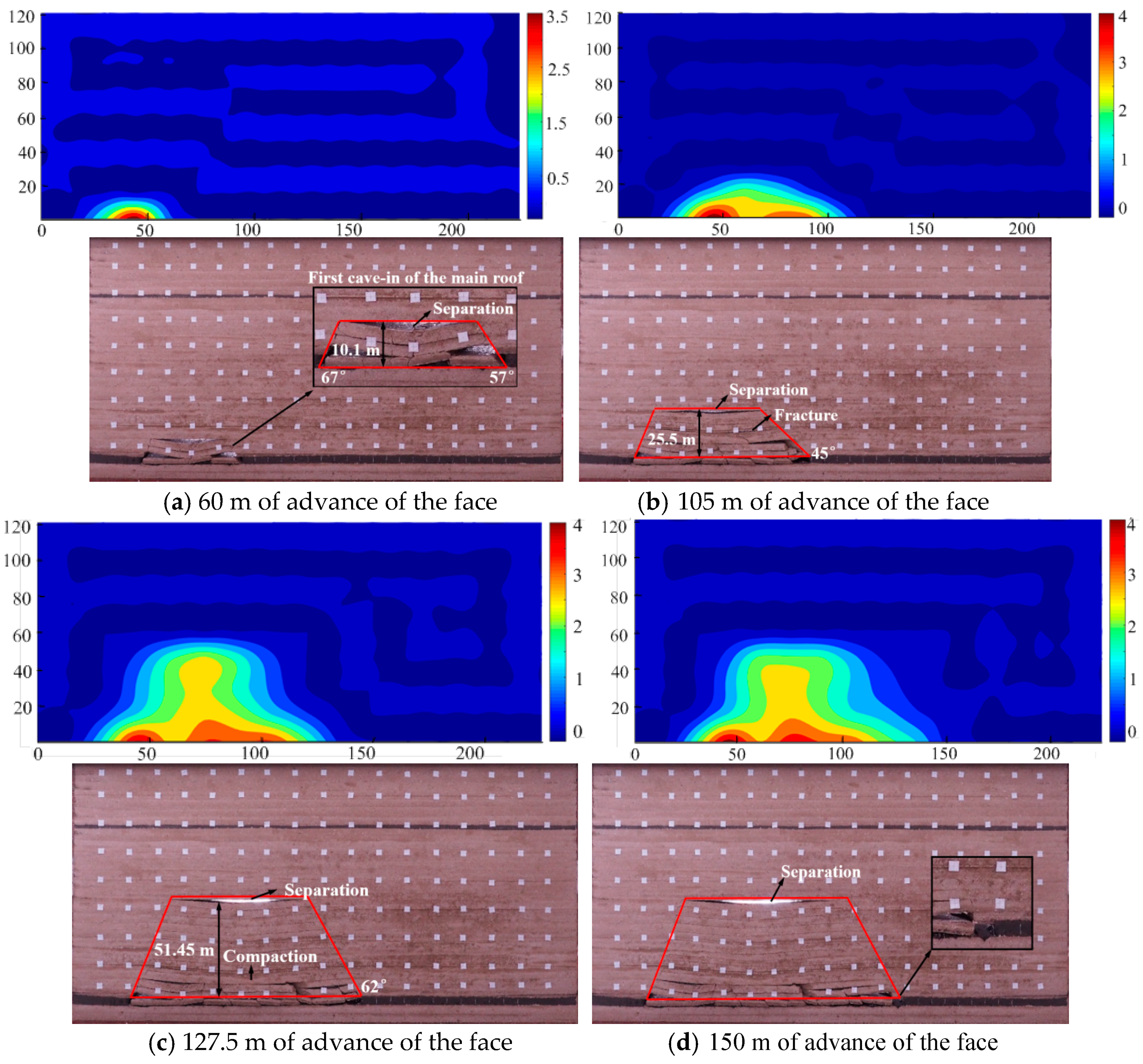
Some key results from physical modeling are given in
Figure 9.
Figure 4 shows that when the face advanced 60 m (
Figure 9a), the limit span of the main roof was reached when the first weighting occurred. Three sublayers caved; the displacement at the middle is the largest with the maximum value of 3.86 m. The height of the caved was 15 m.
When the face advanced 105 m, the fourth periodic weighting occurred (
Figure 9b). The caved and fractured zone kept developing; the top boundary of the fractured zone reached 23.9 m. The maximum displacement point is at 75 m away from the set up room and with a displacement value of 4.34 m.
After 127.5 m of the panel was extracted, the fifth periodic weighting was observed (
Figure 9c). The height of caved zone reached 51.45 m. The maximum displacement point is at 97.5 m away from the set up room and with a displacement value of 4.05 m.
As the panel extraction was 150 m, the sixth periodic weighting took place (
Figure 9d). The height of the fractured zone did not change, only the separation became larger with an increase from 3.1 m high and 71.9 m long (
Figure 9c) to 3.7 m high and 86.5 m long (
Figure 9d). Only the maximum displacement changed slightly, with the value of 4.1 m and located 120 m away from the set up room within the gob.
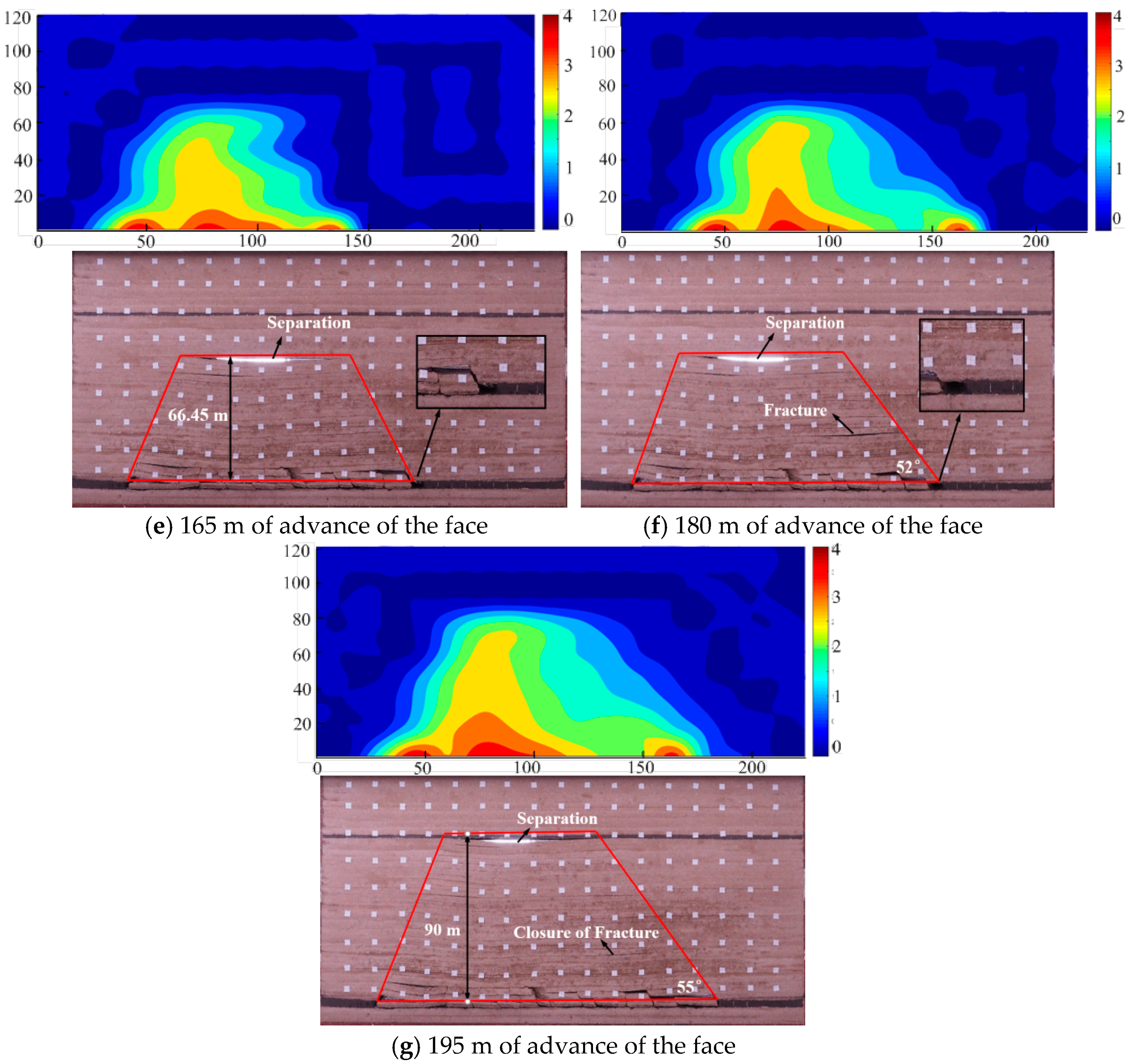
When the face was 165 m away from the set up room, the seventh periodic weighting was noted (
Figure 9e). The top boundary of the fractured zone reached 66.45 m. When the face advanced 180 m, the eighth periodic weighting occurred (
Figure 9f). The height of the fractured zone did not change, but the further separation developed very slightly, with an increase from 3.9 m high 98.6 m long (
Figure 9e) to 4.0 m high and 102.1 m long (
Figure 9f).
Upon completion of 195 m of panel extraction, the ninth periodic weighting occurred (
Figure 9g). The height of the fractured zone was 90 m.
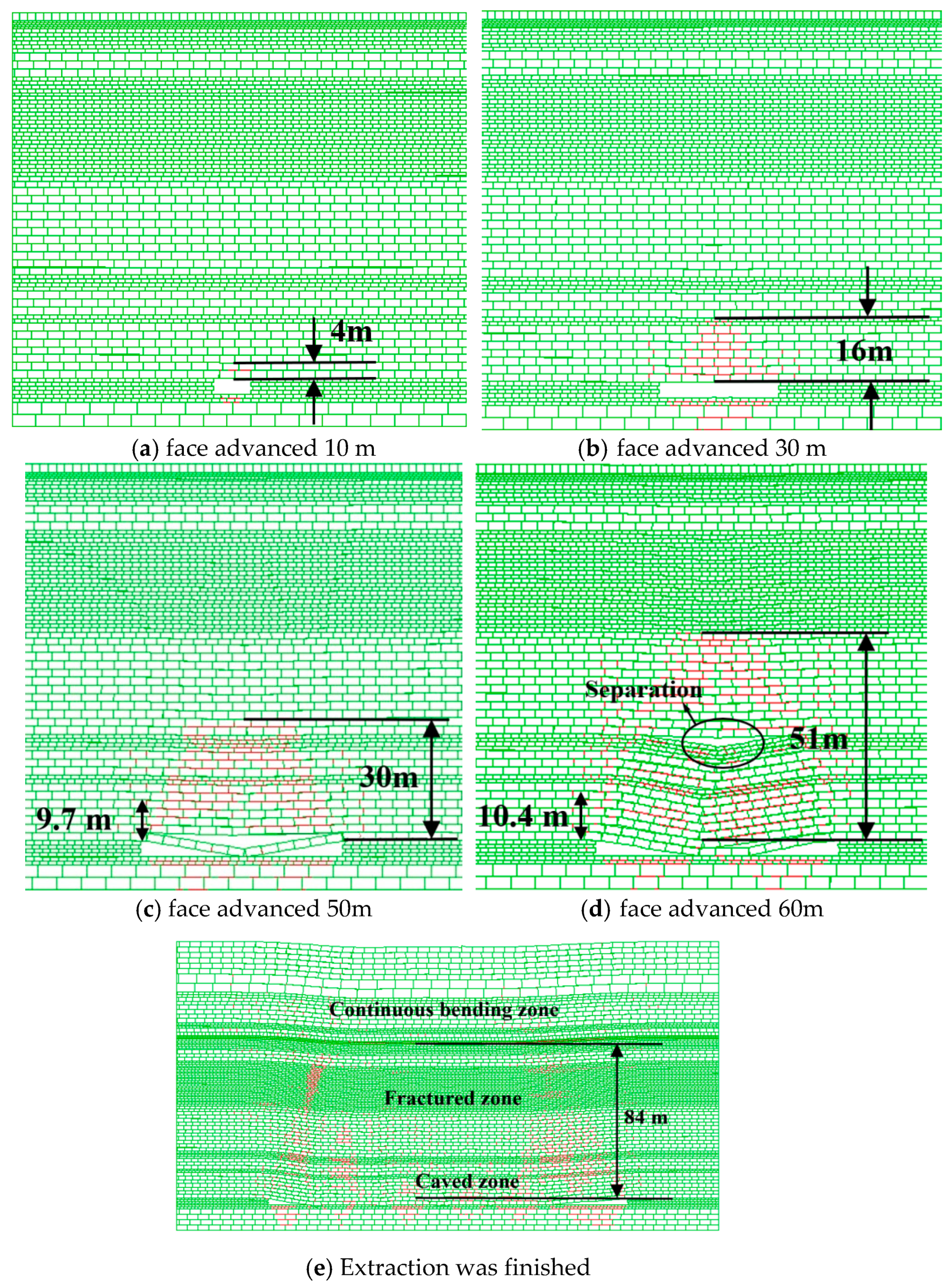
Some selected key modeling results from the numerical modeling are given in
Figure 10.
Figure 10a–c shows that before 50 m of extraction, the roof did not cave, but only deflected or slightly separated. When the overhanging span reached 50 m, the roof broke and caved. At this time, the height of the caved and fractured zone reached 30 m. The 9.7 m of roof sag with its large value is regarded as the cave zone.
Figure 10d shows that when the working face advanced 60 m, the height of the two zones was 51 m. It is obviously observed that there was a large separation; the height from the separation to the coal seam was 25.9 m. The caved zone was 10.4 m, which is consistent with the physical modeling.
Figure 10e shows that after the total extraction of 200 m of coal seam, the supercritical width of extraction was achieved. There was a flat bottomed trough that appeared on the surface. The height of the caved zone and fractured zone was 84 m. This is more or less consistent with the result from the physical modeling (
Figure 10g). Vertical fractures or cracks were developed within the edges of the gob in the roof strata. The gob in the center of the gob was recompacted and reconsolidated wherever fractures (especially horizontal fractures and separations) were reclosed.
The observational data from the field are plotted in
Figure 11. Note that the values for the X axis come from converting the length of a point in the boreholes to the vertical distance of the point to the horizon of the roof of 10,105 tail gate, i.e., L × sin 65° or L × sin 70°.
Data in
Figure 11a show that the fractures from 0 to 48 m were not developed as the water loss was not large with value lower that 7 L/min; however, when it was more than 50 m where the section was located above the caved zone, the water loss increased dramatically. Noticed that from 49 to 81 m, the water loss was more than 10 L/min; this demonstrates that the fractures there were highly developed, but for depths of more than 81 m, water loss became small again with a value of lower than 8 L/min, indicating that the roof strata here were more complete.
Figure 11b shows that fractures were less developed when the depth was less than 63.5 m, as the water loss was basically less than 6 L/min, with only one exception for a point at 43.5 m, where the water loss reached 12.2 L/min. It is believed that this may have been due to the main roof breaking around that point. From 63.5 to 80.4 m, the water loss was more than 10 L/min, with a maximum value of 19.81 L/min. This section was deemed to be within a fractured zone. For sections whose depth were more than 81.5 m, the water loss dropped to 7 L/min.
5. Discussion
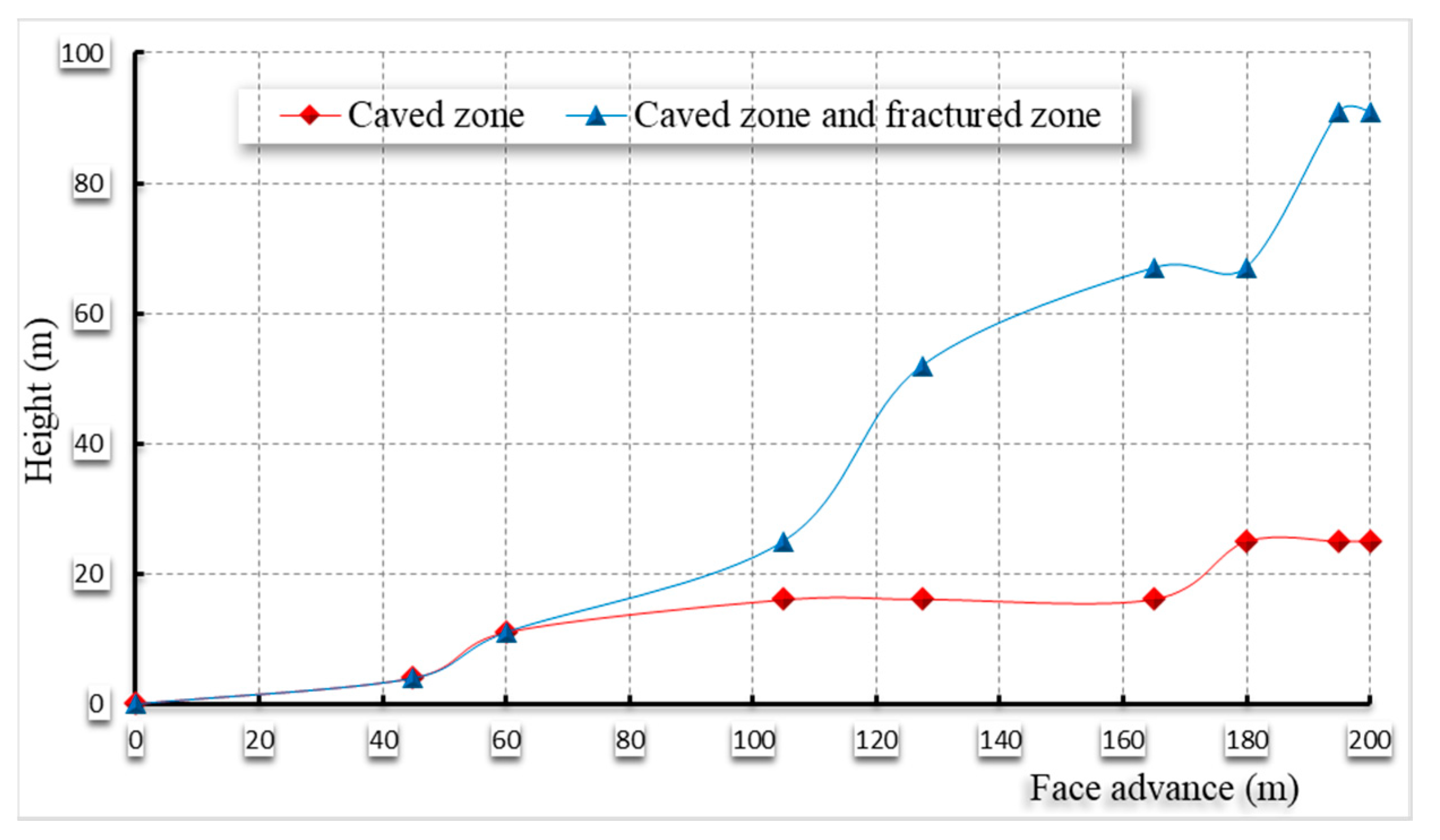
The height of the caved zone and fractured zone is significant in terms of water in-rush and gas drainage. These data of height obtained from the physical modeling are shown in
Figure 12.
Figure 12 shows that at the very beginning of the extraction, the height of the caved zone was equal to that of the fractured zone. When the face advanced 45 m to where the first weighting occurred, the height of the two zones was about 3.4 m above the coal seam. When the face advanced 60 m to where the first periodic weighting occurred, the height of the two zones reached 10.1 m. Following that, the rate of increase of the height of the two zones was faster than that of the caved zone. When the face advanced 105 m, the height of the caved zone was 15 m, and that of the two zones reaches 25.5 m. At that time, the increase rate of the caved is still very slow while that of the two zones increased faster. When the face advanced 127.5 m, the height of caved did not increase while that of the two zones was as high as 51.45 m. When the face advanced 165 m, the height of caved zone still remained unchanged, while a value of 66.45 m of the height of the two zones was achieved. It was not until the face advanced 180 m that the height of the caved zone increased to 25.5 m, but the height of the two zone remained the same. After that, when the face advanced 195 m, the caved zone hardly developed, while the height of the two zones began to increase dramatically, again reaching 90 m. At last, when the face advanced 200 m, the caved zone was 25.5 m high and the height of two zones was 90 m.
In order to present the results quantitatively, the data recorded by the three measuring lines was plotted, as shown in
Figure 13,
Figure 14 and
Figure 15.
Figure 13 shows the displacement of line 1 where the main roof is located 1 m above the coal seam. Before 30 m, the roof only slightly deflected. When extraction reached 50 m, the maximum displacement was at the center (25 m away from the set up room), with a value of 2.05 m. This indicated that the roof did not cave completely. For extraction of 70 m, still, the maximum displacement of the roof was located 25 m away from the set up room, with a value of 3.76 m. This suggests that the main roof caved almost completely and filled the caved zone. After that, the maximum displacement value hardly changed.
Figure 14 presents the displacement of line 2, 31 m above the coal seam, where fine-grained sandstone stratum was located. It is also demonstrated that before 30 m of extraction, the roof hardly moved downward. When extraction reached 50 m, the maximum displacement was also at the center (25 m away from the set up room), but with a value of 0.83 m. This also indicated that the roof did not cave completely. For extraction of 70 m, the maximum displacement of the roof was located 30 m away from the set up room, with a value of 3.08 m. When the face advanced 90 m, the maximum displacement value remained unchanged, but the range with the maximum displacement value of 3.08 m covers about 25 m. When the face advanced 120 m, the maximum displacement reached 3.46 m. The peak point was located around 57 m away from the set up room. After that, the maximum displacement value only slightly changed.
Figure 15 presents the displacement of line 3, 88.5 m above the coal seam where the 2# coal seam stratum was located. It is indicated that before 50 m of extraction, the roof hardly moved downward. This reflects that line 3 was not subjected to the influence of mining, as it was far from the coal seam. However, when extraction reached 70 m, the maximum displacement was at 30 m away from the set up room, with a value of 2.5 m. For extraction of 90 m, the maximum displacement of the roof was located 38 m away from the set up room, with a value of 2.88 m. When the face advanced 120 m, the maximum displacement reached 3.21 m. When the face advanced 150 m, the maximum displacement reached 3.44 m, and the peak point was located around 52 m away from the set up room. When the face advanced 200 m, the flat-bottomed range of the maximum displacement covered about 100 m, and the maximum value hardly changed compared with that of 150 m of extraction.
It is demonstrated from the two boreholes in field observation that the boundary of the fractured zone reached about 81 m above the coal seam where water loss dropped abruptly. Therefore, the height of the two zones, i.e., the caved zone and fractured zone, was about 81 m.
6. Conclusions and Remarks
This paper presents a detailed thorough and comprehensive case study of strata movement in longwall top coal caving in the 10,103 panel at the Baozigou coal mine, especially caved zone and fractured zone development through three research methods: physical modeling, numerical modeling, and field observation.
In the physical modeling, the DICM was employed to capture the roof strata movement due to extraction of the coal seam. UDEC code was used for numerical modeling. High-pressure water injection method was adapted to investigate the fractured zone development in the field.
The result shows that the development of separation and the collapse of the strata were stepped or of leap-type. The separation or the height of the caved and fractured zone may remain the same even when the extraction area is increasing. They develop until a critical point is achieved when the roof strata covering a large distance break and collapse.
The physical modeling showed that the height of the caved and fractured zone was 90 m. The numerical modeling result was 84 m. Field data showed that it was 81 m. These results demonstrate that different methods were consistent, which indicate that the results from this comprehensive study are reliable and scientific.
The study presented in this paper also demonstrates that thorough or comprehensive studies are needed to avoid partial conclusions. It is hoped that the research can provide some insights into ground control in longwall top coal caving mining.


