Abstract
In this paper, we propose an intelligent battery control system that incorporates an active balancing technique and a fuzzy controller to manage and extend the life of an agricultural drone battery efficiently. The control system includes the following key features: A battery pack balancing algorithm based on a bidirectional DC/DC converter; a cell balancing system to prevent overcharge/discharge and ensure equal control of the cell voltages; and a monitoring system and wireless link to track the real-time status of the battery, temperature, and acceleration while the drone is in operation. Each battery pack consists of six lithium polymer batteries, one fuzzy controller per cell, and supports active balancing using the developed balancing technique. The capacity of each of the battery packs in the system is 11,000 mAh, and two can be combined to provide a total capacity of 22,000 mAh.
1. Introduction
The trend toward more electric mobility has demanded the need for high voltage, high efficiency, and long-life battery systems. Thus, the importance of battery balancing technology is growing [1]. There exist many battery balancing schemes that are broadly grouped into either passive or active schemes. All these schemes have their own advantages and disadvantages, and, hence, it is upon the user to decide on which scheme will best work for them [2]. The balancing method should consider balancing speed, efficiency, complexity, and cost according to the intended use [3].
According to the Association for Unmanned Vehicle Systems International (AUVSI), agricultural drones will account for approximately 80% of the drone market in the future. The main disadvantage of current commercially available agricultural drones is that they only support short flights of about 15–20 min. We employ rechargeable secondary batteries with larger capacities compared to the batteries used in hobbyist drones to overcome the short flight time. Examples include lead–acid, nickel–cadmium (Ni–Cd), nickel–metal hydride (Ni–MH), and lithium-ion (Li-ion) batteries. Between them, Li-ion batteries have a number of advantages, including a higher power density by three times compared to lead–acid batteries, high energy density, and low self-discharge rate [4], all of which are properties important to support longer flight times.
Drone batteries for agricultural use require large capacities and typically consist of a monolithic battery module or a pack of several cells connected in a series/parallel manner. However, the inter-cell voltages in this configuration can become unbalanced due to the electrochemical side reactions that occur when charging/discharging and the impedance differences between the battery cells. Moreover, overcharging the battery causes the active material to evaporate, which increases the pressure inside the battery and also increases the corresponding risk of an explosion. Similarly, over-discharging damages the gap structure in lithium-ion batteries, thereby reducing the battery lifetime. Thus, to prevent excessive overcharge/discharge and uneven cell voltages, a cell balancing system is essential [5].
We proposed a battery cell balancing algorithm using a fuzzy controller to solve the DoD (Depth of Discharge) of a high-power drone battery pack. The charging efficiency improvement of the battery pack through the fuzzy control, which has been studied recently, is the same, but it is applied to the drone to control the output through the improvement of the DoD.
Conventional cell balancing techniques include passive balancing methods using resistors and active balancing methods using inductors, capacitors, and power change devices.
Passive balancing techniques dissipate the energy of a relatively high state-of-charge (SOC) battery cell as heat [6]. These techniques require a simple circuit configuration and are inexpensive; however, when the energy is dissipated using resistance, these methods generate a considerable amount of heat and are relatively slow. By contrast, active balancing techniques transfer energy from cells with a high SOC to cells with a low SOC, and the corresponding circuit configuration is more complicated than that in the passive balancing technique. However, the balancing process is fast and efficient [7].
Because the capacity of the battery in the proposed design is large, a converter is needed to stabilize the voltage of the inverter. This type of converter is typically configured as a bidirectional DC/DC converter with a proportional-integral (PI) controller; however, PI controllers are better suited for linear systems, while the proposed system is nonlinear. This issue occurs because the mathematical model of the power electronic system and battery depends on the SOC, temperature, and C-rate [8].
In this paper, we propose a battery cell balancing algorithm, a bidirectional DC/DC converter, and a fuzzy controller to solve the balance problem. The proposed algorithm provides stable control of the DC-link voltage of the inverter and supplies the necessary energy to drive the inverter when the drone is ascending. Instead of using a PI controller to manage the bi-directional DC/DC converter, we propose a cell balancing algorithm and a fuzzy controller that is suitable for nonlinear systems. The resulting intelligent battery control system and the proposed algorithm are intended for use in agricultural drones.
Our performance evaluation showed that our proposed battery management system (BMS) has a 25%–30% effective cycle (50–60 cycles out of 200 cycles) compared to the fuzzy control system while keeping the SOC deviation at 7.4% (target range 8%) and cell voltage deviation at 1.5 mV (target range 50 mV). We also confirmed that, by using the proposed BMS, the voltage deviation was reduced, the depth of discharge was improved, and the efficiency was improved by 5% compared to when only a battery is used.
2. Related Work
2.1. Battery Balancing Type
There are two general types of balancing methods: Passive and active methods, as depicted in Figure 1. The main advantage of the passive method is that it has the simplest circuit configuration of all battery balancing algorithms. However, its disadvantage is that the energy is dissipated through resistance as heat. By contrast, active balancing methods balance overcharge/over-discharge batteries using capacitors, inductors, and power converters [9].
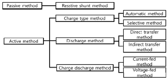
Figure 1.
Battery balancing types.
Active methods can be categorized into charge and discharge methods and the charge method can be further divided into a central type of balancing method and a cell control balancing method. When the cell voltage becomes unbalanced as the battery discharges, the central balancing method causes the primary side switch to turn off while the secondary battery starts charging the battery cell. The advantages of this approach are that it is inexpensive and has a simple control structure. However, the disadvantage is that the cells cannot be independently controlled.
The discharge-type balancing technique controls the balance of the discharge cell with either a 1:N structure or a 1:1 structure. The 1:N structure is a serial connection to the battery, and an individual cell equalizer (ICE) is included in each cell. The configuration of an ICE consists of a power semiconductor switch, a transformer, and a diode. When the cell becomes unbalanced due to overcharging, the ICE of the corresponding cell is operated to discharge the battery. At this point, the energy is discharged into an adjacent cell, the structure of which is bundled into a battery string such that high-voltage stress is applied to the diode. The 1:1 scheme is a method of balancing cells by controlling the discharge of adjacent cells. The control method is as follows. The overall balance among the cells is maintained by discharging cells with higher voltages in the upper layers into cells with lower voltages in the lower layers. In contrast to the 1:N scheme, the 1:1 scheme has low-voltage stress but a long balancing time because it operates by controlling the discharges of two adjacent cells.
2.2. Fuzzy Logic Controller Structures
The concept of fuzzy theory was first published by Zadeh, L.A. in 1965 and has been used in actual applications since Mamdani successfully controlled vapor in 1974. Since then, it has been proven that fuzzy theory can be applied to control systems. Fuzzy control is a cognitive control method that is based on human knowledge and experience [10]. However, it is necessary to formulate the system properly when implementing a PI controller or improved control system [9]. Fuzzy control is a linguistic control method that determines the control input based on certain rules.
If a fuzzy system is used, the power conversion system is complicated, and with an inductor or capacitor, the characteristics vary depending on the driving temperature and switching frequency. Such a complex system involves uncertain information, though excellent results can be obtained with a fuzzy system in the absence of a mathematical model [9]. Figure 2 shows the structure of a general fuzzy controller [11,12].

Figure 2.
Structure of a general fuzzy controller.
2.2.1. Fuzzification
During fuzzification, the deviation and variation rate of the two inputs of the fuzzy controller are converted into new fuzzy values that can be handled in the fuzzy controller by way of a membership function. During the conversion to a fuzzy value, the two inputs define the number of language variables through a language description. These language variables depend on the controller to be designed, and are divided into 7 steps as shown in Table 1.

Table 1.
Common language variable definitions.
The attribution function for these language variables is defined as shown in Figure 3 [11].
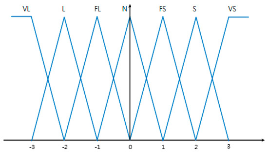
Figure 3.
Membership function.
2.2.2. Rule Base
The rule base is configured based on the experience and knowledge of the designer. Through this rule base, appropriate fuzzy control values are derived for each fuzzy input using the IF-THEN method, where the IF clause is the premise and the THEN clause is the consequent. An example of the rule base is shown in Table 2 [11].

Table 2.
Rules table for language variables.
2.2.3. Inference
The inference is used to infer conclusions regarding definite values using the rule base of the input and the fuzzy function of the fuzzy unit [13]. For example, assuming x = 1.3 and y = 0.8, we can apply the following:
Rule 1) IF x is S and y is FS THEN u is L
Rule 2) IF x is S and y is N THEN u is FS
Rule 3) IF x is FS and y is FS THEN u is FL
Rule 4) IF x is FS and y is N THEN u is FL
Rule 2) IF x is S and y is N THEN u is FS
Rule 3) IF x is FS and y is FS THEN u is FL
Rule 4) IF x is FS and y is N THEN u is FL
To quantify the first part of the IF clause, a definite value can be obtained using the MIN function in Equation (2).
Rule 1) MIN (uS (x = 1.3) = 0.3, uFS (y = 0.8) = 0.8) = 0.3
Rule 2) MIN (uS (x = 1.3) = 0.3, uN (y = 0.8) = 0.2) = 0.2
Rule 3) MIN (uFS (x = 1.3) = 0.7, uFS (y = 0.8) = 0.8) = 0.7
Rule 4) MIN (uFS (x = 1.3) = 0.3, uN (y = 0.8) = 0.2) = 0.2
Rule 2) MIN (uS (x = 1.3) = 0.3, uN (y = 0.8) = 0.2) = 0.2
Rule 3) MIN (uFS (x = 1.3) = 0.7, uFS (y = 0.8) = 0.8) = 0.7
Rule 4) MIN (uFS (x = 1.3) = 0.3, uN (y = 0.8) = 0.2) = 0.2
2.2.4. Defuzzification
The deterministic values obtained through reasoning are parts of the output of the most appropriate controller, and the values obtained through the inference process are expressed as specific values. The result of Equation (2) can be expressed through a MIN operation as the premise with the output level through the MIN operation as the consequent [11]. A fixed value representing the degree of output can be calculated using the center-of-gravity method, as expressed by Equation (3),
where ucrisp is the definite value of the output, bi is the center of the gravitational function indicating the degree of the output of rule i, and μ (i) is the area of the output accuracy value.
2.3. Two-Phase Interleaved Bi-Directional DC/DC Converter
The system used in this paper consists of two battery packs and two converters and provides an output voltage of 50 V. As the battery has a low voltage-to-current characteristic, a two-phase interleaved method per battery pack was applied to reduce the current required from each converter.
Therefore, given that the output voltage is 50 V, each converter has an output voltage of 12 V, and converters are installed in a total of 12 cells. As a non-isolated boost DC/DC converter is used in the proposed system, battery packs consisting of six cells were chosen. The system operates synchronously to enable high efficiency and a bidirectional power flow, as shown in Figure 4.
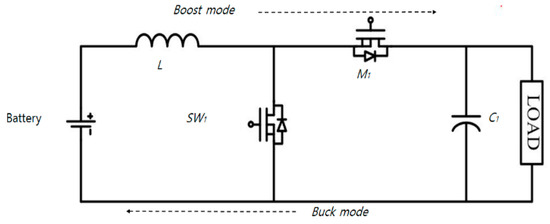
Figure 4.
Synchronous bidirectional boost converter.
The boost ratio of each converter in the system was limited, and multiple converters were configured in series to realize an output voltage of approximately 50 V. The battery module algorithm was then optimized for this converter configuration.
Figure 5 depicts the two-phase interleaved bi-directional DC/DC converter design. In the figure, SW1 represents the main switch gate signal of Boost Converter 1 and SW2 represents the gate signal of the main switch of Boost Converter 2. Two-phase interleaving was applied, and the two gate signals have a phase difference of 180°. This causes the input current to appear as the sum of the two inductors, which doubles the switching frequency and reduces the ripple in the input current. In one cycle, the inductor current is divided into rising and falling sections and the amount of each current change is identical.
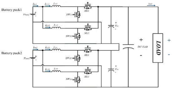
Figure 5.
Synchronous bidirectional boost converter.
3. Development of the Proposed Agricultural Drone Battery Cell Balancing Algorithm
The SOC information of each battery pack is required to perform battery cell balancing because the SOC is an indicator of the charged state (remaining capacity) of the battery. As the battery generates electricity by chemical reaction, it is difficult to accurately measure the SOC. Instead, the SOC must be estimated.
3.1. SOC Estimation Algorithm with Improved Current Integration
The proposed system includes an improved SOC estimation algorithm that addresses the shortcomings in existing current integration methods used for battery cell balancing in agricultural drones. In existing current integration methods, sensor errors and noise are allowed to accumulate [14]; however, in the proposed system, the accumulated error is periodically reset through the battery model [15]. This model is based on an improved shepherd battery model (ISBM). The existing shepherd battery model has a major drawback, i.e., it cannot be used to simulate the transient characteristics of the battery, because it incorporates the internal resistance of the battery. Instead, in the proposed algorithm, the open-circuit voltage (OCV) of the battery [13] was calculated by applying an ISBM that includes a parallel resistor–capacitor (RC) circuit like that in a Thevenin battery model (TBM) [16]. Here, the OCV refers to the potential difference between both terminals of a cell or battery when the voltage circuit is open in a no-load state. The OCV-SOC table was calculated by measuring the cumulative error for each 10% change in the SOC [16,17]. Then, SOC estimation was performed based on the accumulated error. A flowchart illustrating the SOC estimation algorithm is shown in Figure 6.
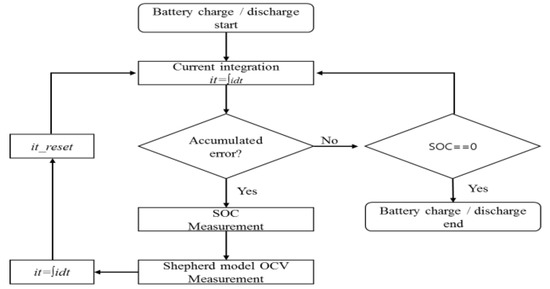
Figure 6.
Flowchart of the proposed state-of-charge (SOC) estimation algorithm.
3.2. Battery Cell Balancing Algorithm
In this paper, we propose a battery cell balancing algorithm that reduces the differences in the SOC between battery cells to maximize the life of the battery. Given that the SOC is different for different cells in the battery due to imbalances, the amount of discharge from cells that have a relatively high SOC is increased, while the amount of discharge from cells that have a relatively low SOC is decreased. In this way, the cells are balanced.
The output terminals of each converter cell are connected in series so that the output current magnitudes of each of the converters are identical. As the input/output power of the converter is ideal, it can be calculated using Equation (4).
As the output currents of each of the converters are identical, the discharge power of the battery can be controlled by controlling the output voltage, as per
where PbattN is the input power of the Nth module, PoN is the output power of the Nth converter, voN is the output voltage of the Nth converter, and ioN is the output current of the Nth converter. The output voltage of each converter module is determined by the fuzzy controller.
PbattN ≈ P0N
Pbatt1 ≈ iovo1 ∝ vo1
Pbatt1 ≈ iovo2 ∝ vo2
Pbatt1 ≈ iovoN ∝ voN
Pbatt1 ≈ iovo2 ∝ vo2
Pbatt1 ≈ iovoN ∝ voN
3.3. Fuzzy Controller Design for Battery Module Balancing
The DC-link control value of the output voltage of each converter module is obtained through fuzzy control. The basic structure of the fuzzy controller is shown in Figure 7.
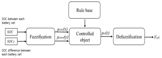
Figure 7.
Definition of the membership function.
3.3.1. Fuzzification
In fuzzification, the SOC difference between the SOC and cell of each battery cell, two input values of the fuzzy controller, is converted into a new fuzzy value that can be handled by a fuzzy controller through a membership function.
During the conversion to a fuzzy value, the two input values of the controller are defined as language variables using the language description in Table 3. As shown in the table, the applied language variable is defined in five steps for the two input and output values of the fuzzy controller.

Table 3.
Definition of the language variable for the SOC of a battery cell.
The SOC of the battery is divided into five levels representing a range of 20–80%. The reason for this configuration is because at values above 80%, lithium batteries become unstable and have an increased risk of explosion, while values below 20% are considered very small and within the cut-off range of the battery.
The SOC difference between battery cells is defined using the language variables shown in Table 4.

Table 4.
Definition of the language variables for the SOC difference between battery cells.
The maximum SOC difference is set to 20%, the discharge current amount is increased when the difference is 20% or more, and the discharge current amount is decreased when the difference is 0%, which will ensure that the batteries will operate in their stable range. The membership function for these language variables is shown in Figure 8.
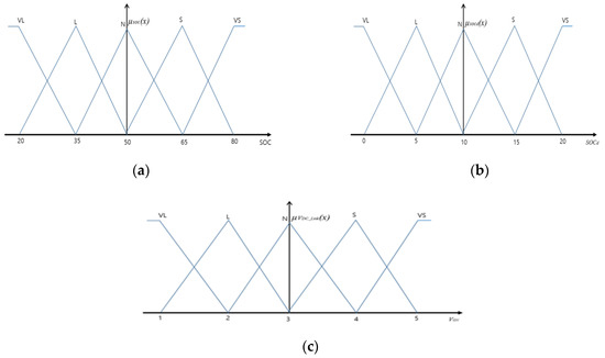
Figure 8.
Definition of the membership function: (a) Membership function for the battery cell SOC. (b) Membership function for the SOC difference between battery cells. (c) Membership function for the output Von of the converter.
3.3.2. Rule Base
The rule base is designed based on the designer’s experience with and knowledge of battery cell balancing. The rule base used in the applied fuzzy controller is shown in Figure 8 and the appropriate fuzzy control value is derived for the two fuzzy inputs through this rule base.
The rule base is based on “IF-THEN” tests according to the following:
IF SOC is VL and SOCd is N, THEN V0N is VL
IF SOC is L and SOCd is N, THEN V0N is L
IF SOC is N and SOCd is N, THEN V0N is N
IF SOC is L and SOCd is N, THEN V0N is L
IF SOC is N and SOCd is N, THEN V0N is N
3.3.3. Inference
The final output value of the fuzzy controller is obtained by inference and defuzzification. First, inferences are determined using the attribution function in Figure 8 with the rule-based table shown in Table 5. Note that inference methods include the direct, simple, linear, and modified linear inference approaches. The direct inference method, also referred to as the Mandani inference method, was chosen for use in this paper. The process of direct inference is shown in Equations (7) and (8). First, the two inputs SOC = 55 and SOCd = 11 are obtained by way of the attribution function and rule base.
Rule 1: IF SOC is S and SOCd is S, THEN V0N is VS
Rule 2: IF SOC is S and SOCd is N, THEN V0N is S
Rule 3: IF SOC is N and SOCd is S, THEN V0N is S
Rule 4: IF SOC is N and SOCd is N, THEN V0N is N
Rule 2: IF SOC is S and SOCd is N, THEN V0N is S
Rule 3: IF SOC is N and SOCd is S, THEN V0N is S
Rule 4: IF SOC is N and SOCd is N, THEN V0N is N

Table 5.
Definition of the membership function.
To quantify the linguistic and computation of the prepositional verb, a minimum operator is used to obtain the definite value of the preceding verb in Equation (5) by way of Equation (4)
Rule 1: MIN(μS (SOC = 55) = 0.3, μS (SOCd =11), = 0.2) = 0.2
Rule 2: MIN(μS (SOC = 55) = 0.3, μS (SOCd = 11), =0.8) = 0.3
Rule 3: MIN(μN (SOC = 55) = 0.6, μN (SOCd =11), =0.2) = 0.2
Rule 4: MIN(μN (SOC = 55) = 0.6, μN (SOCd =11), =0.8) = 0.6
Rule 2: MIN(μS (SOC = 55) = 0.3, μS (SOCd = 11), =0.8) = 0.3
Rule 3: MIN(μN (SOC = 55) = 0.6, μN (SOCd =11), =0.2) = 0.2
Rule 4: MIN(μN (SOC = 55) = 0.6, μN (SOCd =11), =0.8) = 0.6
3.3.4. Defuzzification
In defuzzification, the definite values as obtained from the inference steps are used to determine the final output value of the fuzzy control [11]. First, to obtain the final output value, the determinants of Equation (8) can be obtained using the MIN operation on the posterior part of Equation (8) and the posterior part of Equations (7) and (9).
The final output value can be obtained through the center of gravity (COG) function of Equation (10) after calculating the output precision using Equation (9).
Rule 1: MIN (0.2, μVS(V0N))
Rule 2: MIN (0.3, μS(V0N))
Rule 3: MIN (0.2, μS(V0N))
Rule 4: MIN (0.6, μN(V0N))
Rule 2: MIN (0.3, μS(V0N))
Rule 3: MIN (0.2, μS(V0N))
Rule 4: MIN (0.6, μN(V0N))
Ideally, the final DC-link value should remain constant. In order to ensure this, the output command voltage is obtained from the ratio of the Nth V0N to the final output value of each converter obtained using Equation (10), as shown in Equation (11).
In Equation (11), V *0N is the output command voltage value of each converter, V0N is the output value through the fuzzy control, and VDC-link is the DC-link value for holding the voltage constant. The output command voltage calculated using Equation (11) controls each switch using Equation (12) to determine the switching duty ratio.
In this way, the discharge power of the battery module can be adjusted by controlling the output voltage of each converter.
4. Development of a Monitoring System
4.1. RF Communication
The communication in this study is accomplished using an audio frequency-shift keying (AFSK) modem over an RF channel, instead of the more commonly used ZigBee standard. This approach was adopted because it can support a higher data rate than ZigBee, and it operates over a wider area. The radio frequency (RF) communications protocol is primarily used for rapid communication of the status of the drone battery to a monitoring station on the ground (see Figure 9). A block diagram and schematic of the RF circuitry are shown in Figure 9 and Figure 10, respectively.

Figure 9.
General typical RF structure.
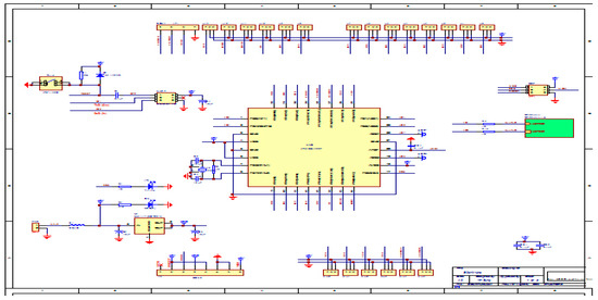
Figure 10.
Manufactured RF circuit diagram.
An AFSK modem was selected as opposed to a frequency-shift keying (FSK) modem because AFSK has better noise characteristics and a high data transmission rate [18]. The resulting module can be configured using either dual in-line package (DIP) switches or non-volatile memory (i.e., EEPROM: Electrically Erasable PROM). The configuration options pertain to the RF channel and the universal asynchronous receiver/transmitter (UART) mode. The module operation status (mode) can be obtained from the green & red LED status, the battery usage application, and the received signal strength indicator (RSSI).
As shown in the schematic, the RF circuitry employs a 3.3–9.0 V power supply and includes a UART for serial communications that can communicate at 3 or 5 V without requiring additional circuitry. The UART includes built-in support for the high-level data link control (HDLC) protocol, which allows easy connections to existing equipment, and provides several functions to ensure robust communication, including module identification to reduce crosstalk, error detection/correction processes, and high-sensitivity reception (−124 dBm).
4.2. Design and Development
In this section, we describe the design and development of the proposed system. During the tests, we analyzed the characteristics of the battery of an agricultural drone using the proposed RF communications method and compared the results to those from a fully wired method. To emulate the spraying of pesticides at an actual site, we used a tank with 20 L of water and conducted the test by flying or hovering 1 m above the ground. Figure 11 shows a photograph of the test setup.

Figure 11.
Testing prototype (a) and the transmission/reception module when mounted on an agricultural drone (b).
The transmitter/receiver system shown in Figure 12 and Figure 13 was developed to serve as a wireless base station and receive data related to battery usage via the RF sensor installed on the drone. The system receives the voltage output (0–3.3 V) from the current sensor and converts it into current using an analog-to-digital converter (ADC) before outputting the data. The conversion ratio of 6.6 mV/A translates to a 6.6 mV change per 1 A of current sensed per mV. An output of 0 V translates to 200 A, an output of 1.65 V represents 0 A, and an output of 3.3 V translates to 200 A.
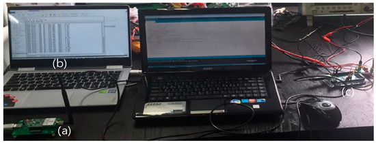
Figure 12.
Drone load measurement by system: Communications -RF 424 MHz, -Transmission output 10 dBm, Receive Sensitivity −124 dBm, Current Sensor: -ACS759, ~200 A/Micom: -Arduino Mega 2560. (The part labeled (a) is the receiver, (b) is the receiver data display, and (c) is the transmitter.).

Figure 13.
Flowchart of the monitoring system.
After the output of the current sensor is converted to a 10-bit value by the ADC, this is then converted to current using the 6.6 mV/A scale factor. The display shows the 10-bit ADC value and the sensor output voltage (mV) and current value. The display data transmission cycle is programmed to send a message once per second. The following conversion factors are used: Voltage = (ADC Value/1023.0) * 5000 (5000 mV because the drive voltage of the Micom is 5 V); amps = (Voltage–ACS offset (1.65 V))/mV per amp (6.6 mV/A) [19].
The proposed scheme implements an active balancing battery management system (BMS) control method. The system receives the cell voltage from the battery monitoring integrated circuit (IC) via a serial peripheral interface (SPI), calculates the minimum value and deviation of each cell, and turns on the balancing switch for each cell where there is a difference of 50 mV or more.
When the cell deviation value falls below 50 mV, the cell balancing switch is turned off and the battery voltage and current flowing through the Field Effect Transistor (FET) are passed to the ADC so that the values can be used to control the charging and discharging processes. In addition, the charge and discharge FET gate is opened at 10 ms intervals to measure the direction of the voltage and current and to detect and control the charge and discharge state. The battery charge is determined based on the battery voltage and is used to decide when to cut off the charge and discharge.
5. Development of an Agricultural Drone BMS
A photograph of the main control board used to control the charging/discharging of the battery is shown in Figure 14. The charge/discharge circuitry is located at the center of the mainboard and is designed to manage 220 at 120 A. In total, charging the lithium polymer battery requires 1–2 h at 22.2 V/22 A, and the battery can be discharged up to 8–10 C-rate. The cell balancing circuitry, denoted by ③ in the figure and located under the mainboard, can control 12 cells at a time and is designed to provide active balancing using a fly-back circuit.
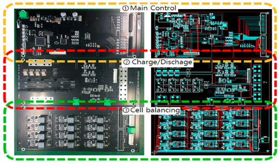
Figure 14.
Mainboard and description of each part.
Figure 14 shows test messages applied with the RC5 encryption algorithm (Agarwal et al., 2013). The RC5 encryption algorithm can be applied to low-power, low-memory, and high-security applications. For high encryption and a low running time, the values of the ‘Key’ and the number of ‘Rounds’ are calculated.
5.1. Charge/Discharge Test to Verify the Performance of the System
A charge/discharge test was conducted to verify the performance of the system. The test conditions were as follows: Charging 50 V, resting 30 min, discharging 40 V, and resting 30 min, based on 200 cycles/one cycle (mean 200 charge/discharge cycles per test).
Figure 15 shows that a change in the DOD (depth of discharge) occurred after 100 cycles, as indicated by the sharp increase in the charging time per cycle. Moreover, when the results for the proposed BMS are compared to those of the fuzzy control system, unlike the battery state when it is not used, it could be confirmed that 50–60 cycles were effective.
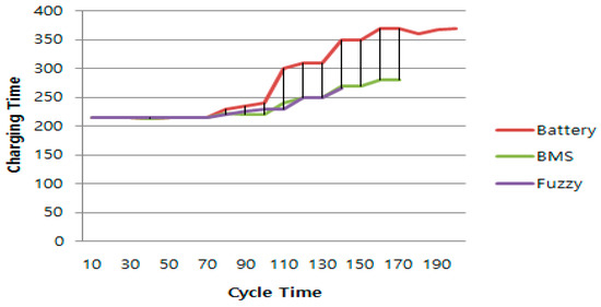
Figure 15.
A 50 V charge time comparison per cycle.
A comparison of discharging at 0.2 and 6 C-rate between the battery alone and with the BMS is shown in Table 6.

Table 6.
Comparing the discharge of the battery alone versus that with the battery management system (BMS).
- The purpose of this test is to compare the discharge efficiency between a typical battery versus the BMS when discharging at 0.2 and 6 C-rate with a 0.5 C-rate charge, and the test compares the discharge efficiency when only the battery and when the BMS are installed.
- In the comparison, no significant differences were observed in the discharge amounts, but the changes over time showed that the discharge time was longer in the BMS case.
- In particular, especially as shown in Table 6, a rapid voltage drop was observed at a voltage of 40 V, and it was confirmed that a discharge followed according to the gentle curve observed at approximately 4% when using the BMS.
5.2. Cell Voltage Deviation and SOC Measurement
The SOC and cell voltage deviation of the battery management board (see Figure 16) were measured to determine whether the voltage deviation values between the SOC and cell measured in charge/discharge units when under the control of the BMS were appropriate. The experimental method was as follows. After two lithium polymer batteries were connected in series and the batteries were discharged to 40 V and recharged to 45 V, the Ah value was measured by both the charge/discharge device and the BMS system. Table 7 is calculated to know the SOC and cell voltage deviation measurement data values. In addition, Table 8 is a voltage value measured for each of the 12 cells of the agricultural drone battery. If the system is working properly, the measured value should be within ±8% for the SOC. The cell voltage deviation was determined by measuring the voltage between the 12 cells of the battery while charging to 45 V and comparing this outcome to the voltage measured using the BMS. Ideally, the measured voltage should be within 50 mV or less of the target.

Figure 16.
Embedded battery management board and an example of how the cell voltage was measured.

Table 7.
SOC and cell voltage deviation measurement data.

Table 8.
Measured voltage for each cell.
The results of the measurement indicated that the SOC deviation was 7.47% and was within the target range of 8%. In addition, the maximum deviation of the cell voltage was measured and found to be 0.0015, which was within the target of 50 mV.
Figure 17 and Figure 18 are graphs measuring the discharge amount between a typical battery (a) and a battery (b) equipped with bms based on 0.2C-rate and 0.6C-rate. As a result of the graph, it can be seen that the battery (b) equipped with bms lasts longer than the normal battery (a).
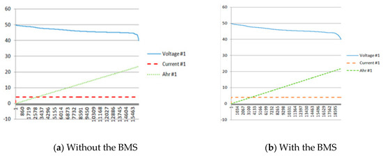
Figure 17.
Comparison of the 0.2 C discharge outcomes: (a) Battery only, and (b) with the BMS.
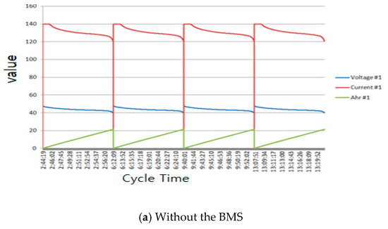
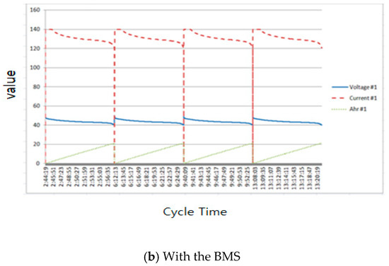
Figure 18.
Comparison of a 0.6 C discharge outcomes: (a) Battery only, and (b) with the BMS.
Figure 19 compares the battery discharge of agricultural drones with the developed BMS (Figure 19a) and without the BMS (Figure 19b). In the charged state, it was confirmed that the voltage differences between the cells with the BMS installed and with only the battery were not large. This occurred because the C-rate is not high in the charged state, resulting in little to no difference. In the discharged state, voltage differences were observed between the cells when only the battery was installed on the right side and the BMS was installed on the left side.
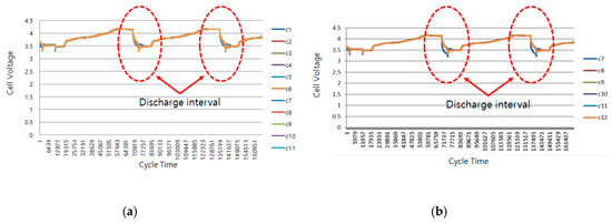
Figure 19.
Cell change comparison in the discharge interval of the drones ((a): BMS, (b): Battery only).
In this case, the battery had six cells per pack, although the system also supports two packs with 12 cells each. When 7–12 cells were installed, a large difference was observed at the seventh cell. This occurred because the voltage deviation increased when the sixth and seventh cells were connected to the first cell, as shown in Figure 20.
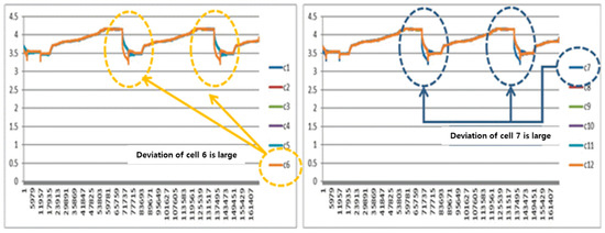
Figure 20.
Comparison of the voltage deviation of each battery cell.
Based on these results, it was confirmed that when the BMS was used, the voltage deviation was reduced and the DOD was improved.
In this study, we found that the efficiency was improved by 5% when the developed BMS was installed compared to when the battery-only method was used. In actual flight, the 5% efficiency improvement is improved even further due to the climate and temperature, showing an efficiency rate exceeding 10% while charging and discharging (Refer to Table 9).

Table 9.
Comparison of outcomes with the battery only and the BMS.
We anticipate that if the proposed battery pack and integral BMS are commercialized, it will be shown to be useful during the operation of agricultural drones due to the extended battery life and reduced charge time.
6. Conclusions
In this paper, an intelligent battery pack balancing algorithm intended for use in an agricultural drone was proposed. The use of a lithium polymer battery is associated with difficulties when analyzing the system because this type of battery generates electricity by way of a chemical reaction. To resolve this, we proposed an intelligent balancing algorithm using fuzzy control because such a method does not require analysis with a mathematical model. The method of communication was designed using AFSK and RF instead of the more commonly used ZigBee to ensure that there was sufficient bandwidth for the required data and to cover a larger area. This system allows the voltage data values that describe the status of the battery cell to be sent efficiently and rapidly. In order to apply fuzzy control to the proposed battery pack module balancing algorithm, a fuzzy controller was developed by analyzing and adapting the general fuzzy control theory. A field test was also conducted to determine the efficacy of the battery pack module algorithm proposed in this paper, and it was confirmed that it was able to control the discharge current by controlling the output voltage.
In this study, we found that the efficiency improved by 5% when the developed BMS was installed compared to when only a battery was used. In actual flight, the 5% efficiency improvement could be improved even further during certain climate and temperature conditions, showing an efficiency exceeding 10% while charging and discharging. We have anticipated that if the proposed battery pack and integral BMS are commercialized, it will be proven to be useful during the operation of agricultural drones given the extended battery lifetimes and reduced charge times.
Author Contributions
Contributions, Conceptualization, S.-B.K. and S.-H.L.; methodology, S.-B.K. and S.-H.L.; software, S.-B.K.; validation, S.-B.K. and S.-H.L.; formal analysis, S.-H.L.; investigation, S.-B.K. and S.-H.L.; resources, S.-B.K. and S.-H.L.; data curation, S.-B.K.; writing—original draft preparation, S.-H.L.; writing—review and editing, S.-B.K.; visualization, S.-H.L.; supervision, S.-B.K. All authors have read and agreed upon the published version of the manuscript.
Funding
This research received no external funding.
Conflicts of Interest
The authors declare no conflicts of interest.
References
- Vardwaj, V.; Vishakha, V.; Jadoun, V.K.; Jayalaksmi, N.S.; Agarwal, A. Various methods used for battery balancing in electric vehicles: A comprehensive review. In Proceedings of the 2020 International Conference on Power Electronics & IoT Applications in Renewable Energy and its Control, Mathura, India, 28–29 February 2020. [Google Scholar]
- Omariba, Z.B.; Zhang, L.; Sun, D. Review of battery Balancing methodologies for optimizing battery pack performance in electric vehicles. IEEE Access 2019, 7, 129335–129352. [Google Scholar] [CrossRef]
- Yildirim, B.; Elgendy, M.; Smith, A.; Pickert, V. Evaluation and Comparison of Battery Cell Balancing Methods. In Proceedings of the 2019 IEEE PES Innovative Smart Grid Technologies Europe (ISGT-Europe), Bucharest, Romania, 29 September–2 October 2019. [Google Scholar]
- Lee, Y.S.; Duh, J.Y. Fuzzy-controlled individual-cell equalizer using discontinuous inductor current-mode Cuk convertor for lithium–ion chemistries. IEE Proc. Electr. Power Appl. 2005, 152, 1271–1282. [Google Scholar]
- Li, X.; Hui, D.; Lai, X. Battery energy storage station (BESS)-based smoothing control of photovoltaic (PV) and wind power generation fluctuations, Sustainable Energy. IEEE Trans. 2013, 4, 464–473. [Google Scholar]
- Ranjbar, H.; Banaci, A.; Khoobroo, A.; Fahimi, B. Online estimation of state of charge in Li-Ion batteries us-ing impulse response concept, Smart Grid. IEEE Trans. 2012, 3, 360–367. [Google Scholar] [CrossRef]
- Yu, L.R.; Hsieh, Y.-C.; Liu, W.; Moo, C.S. Balanced discharging for serial battery power modules with boost converters. In Proceedings of the 2013 International Conference (ICSSE), Budapest, Hungary, 4–6 July 2013; pp. 449–453. [Google Scholar] [CrossRef]
- Bose, B.K. Modern Power Electronics and AC Drives; Prentice Hall PTR: Indianapolis, IN, USA, 2001. [Google Scholar]
- Thomas, S.; Zhu, W. A targeted equalizer for lithium ion battery packs. In Proceedings of the IEEE Vehicle Power and Propulsion Conference, Dearborn, MI, USA, 7–10 September 2009; pp. 175–180. [Google Scholar]
- Lee, S.H.; Cho, S.E.; Moon, K. Fuzzy modeling and control of system interconnected photovoltaic power generation system. Int. Inf. Inst. 2015, 18, 1283–1292. [Google Scholar]
- Lee, S.-H. Development of Fuzzy controller for battery cell balancing of agricultural drones. J. Instit. Internet Broadcast. Commun. 2017, 17, 199–208. [Google Scholar]
- Lee, S.H.; Lee, S.J.; Moon, K.I. Application of Fuzzy Feedback Control for Warranty Claim, New Challenges for Intelligent Information and Database Systems; Springer: Berlin/Heidelberg, Germany, 2011; pp. 279–288. [Google Scholar] [CrossRef]
- Lavigne, L.; Sabatier, J.; Francisco, J.; Guillemard, F.; Noury, A. Lithium-ion Open Circuit Voltage (OCV) curve modelling and its ageing adjustment. J. Power Sour. 2016, 324, 694–703. [Google Scholar] [CrossRef]
- Rivera-Barrera, J.P.; Muñoz-Galeano, N.; Sarmiento-Maldonado, H.O. SoC Estimation for Lithium-ion Batteries: Review and Future Challenges. Electronics 2017, 6, 102. [Google Scholar] [CrossRef]
- Xiong, R.; Sun, F.; Hongwen, H.; Nguyen, T.D. A data-driven based adaptive state of charge estimator of lithium-ion polymer battery used in electric vehicles. Energy 2013, 63, 295–308. [Google Scholar] [CrossRef]
- Tian, N.; Fang, H.; Chen, J.; Wang, Y. Nonlinear Double-Capacitor Model for Rechargeable Batteries: Modeling, Identification, and Validation. IEEE Trans. Contr. Syst. Tech. 2020, 1–15. [Google Scholar] [CrossRef]
- Meng, J.; Luo, G.; Ricco, M.; Swierczynski, M.; Stroe, D.; Teodorescu, R. Overview of Lithium-Ion Battery Modeling Methods for State-of-Charge Estimation in Electrical Vehicles. Appl. Sci. 2018, 8, 659. [Google Scholar] [CrossRef]
- Akyildiz, F.; Su, W.; Sankarasubramaniam, Y.; Cayirci, E. Wireless Sensor Networks: A Survey. Elservier Comput. Netw. 2002, 38, 393–422. [Google Scholar] [CrossRef]
- Lee, S.H.; Kim, S.B.; Yang, S.H. Design of drone battery usage monitoring system using wireless sensor network. In Proceedings of the 3rd International Integrated (Web & Offline) Conference & Concert on Convergence with Academic & Job (IICCC 2017, SCCTL 03), Lao-Korean College, Vientiane, Laos, 8–12 August 2017; pp. 161–164. [Google Scholar]
© 2020 by the authors. Licensee MDPI, Basel, Switzerland. This article is an open access article distributed under the terms and conditions of the Creative Commons Attribution (CC BY) license (http://creativecommons.org/licenses/by/4.0/).