Article

Axial Plasma Spraying of Mixed Suspensions: A Case Study on Processing, Characteristics, and Tribological Behavior of Al2O3-YSZ Coatings

1
Department of Engineering Science, University West, 46132 Trollhättan, Sweden
2
Treibacher Industrie AG, 9330 Althofen, Austria
3
International Advanced Research Center for Powder Metallurgy and New Materials, Hyderabad 500 005, India
4
Applied Materials Science, Uppsala University, 75121 Uppsala, Sweden
5
Physics Department, University of Bari, via Amendola 173, 70126 Bari, Italy
*
Author to whom correspondence should be addressed.
Appl. Sci. 2020, 10(15), 5140; https://doi.org/10.3390/app10155140
Submission received: 13 May 2020 / Revised: 19 July 2020 / Accepted: 22 July 2020 / Published: 27 July 2020
(This article belongs to the Special Issue The Applications of Plasma Techniques)

Abstract

:
Thermal spraying deploying liquid feedstock offers an exciting opportunity to obtain coatings with characteristics vastly different from those produced using conventional spray-grade powders. The most extensively investigated variant of this technique is Suspension Plasma Spraying (SPS), which utilizes a suspension of fine powders in an appropriate medium. The relatively recent advent of axial feed capable plasma spray systems can enable higher throughputs during SPS, provides the possibility for spraying with longer stand-off distances, and also permit the use of suspensions with higher solid loading. The present work investigates axial plasma sprayed coatings produced using a mixed suspension of fine (submicron or nano-sized) powders of Al2O3 and YSZ as a case study. Deposition of the mixed suspension using axial injection plasma spraying, comprehensive evaluation of characteristics of the resulting coatings, and assessment of their tribological behavior were of particular interest. Evaluation of surface morphology, microstructure, and hardness of the coatings reveals that axial SPS of mixed suspensions provides an exciting pathway to realize finely structured multi-constituent coatings using suspensions with as high as 40 wt.% solid loading. The study of scratch, dry sliding wear, and erosion behavior also specifically shows that the addition of YSZ in the Al2O3 matrix can improve the tribological properties of the coating.

1. Introduction

Thermal spray processes have been widely used for deposition of coatings for various industrial applications, such as aerospace, pulp, and paper, machinery, petrochemical, biomedical, etc. [1]. Ceramic coatings are usually deposited by atmospheric plasma spraying (APS) from powder feedstock, with the powder particle size typically varying from 20 to 50 µm, thus resulting in coarse-structured coatings with typical splat sizes being several tens of microns. A sharp increase in the number of recent studies on the subject reflects the growing interest in the deposition of fine-structured coatings (i.e., with submicron and nano-sized features) with enhanced functional performance in terms of wear, erosion, thermal barrier properties, etc. compared to corresponding conventional coarse-structured coatings [2,3,4,5,6,7,8,9,10]. One of the most desirable routes for the production of such coatings involves thermal spraying of fine (submicron and nano-sized) particles. However, use of such fine-sized feedstock poses significant challenges, with the difficulty in injecting nano- and submicron-sized particles into the thermal spray plume/flame being the most dominant [4]. Another major issue related to the injection of fine powders is their tendency to agglomerate, which can clog the delivery line from the powder feeder or choke the plasma torch nozzle itself, thereby hindering smooth and reliable powder flow and producing non-uniform and inferior quality coatings. The fine particles also typically possess poor flowability and, because of their inherently low momentum, they cannot easily penetrate the high-velocity gas streams associated with thermal spray techniques, thereby compromising controlled powder feeding [7]. The use of high carrier gas flow rates are required for enabling such particles to penetrate the plasma plume, and this can detrimentally perturb the plasma jet [10]. Spraying sub-micron or even finer powders can also present a health concern at the workplace. Although attempts to agglomerate the nano-/submicron-sized particles have been made, inhomogeneous melting characteristics of the agglomerated particles in the plume have often been noted [5,9].
To overcome the above challenges associated with the production of finely structured coatings, the submicron/nano-sized powder can be suspended in an aqueous or organic solvent and such a suspension used as the feedstock for thermal spraying. Thus, the process merely requires a stable suspension of the powder material to be coated, prepared in a suitable aqueous or organic solvent. Plasma spraying has been the spray technique of choice for a vast majority of suspension-based coating efforts, due to the availability of a high-energy flux that is needed for the added step of eliminating the solvent in case of a suspension feedstock. The above approach forms the basis for the increasingly interesting Suspension Plasma Spray (SPS) technique, which has already been shown to be capable of producing coatings with diverse microstructural features ranging from extremely porous to very dense, columnar, vertically cracked, etc. [11,12,13,14,15]. Such unique and novel microstructures are not usually obtained through conventional thermal spraying using powder feedstock. Such varied microstructures are beneficial for a wide range of distinct applications, including Thermal Barrier Coatings (TBCs) in gas turbines and aero engines [16], electrolytes for solid oxide fuel cells [17], coatings for wear protection [18], biocompatible coatings for implants [19,20], electron-emitting coatings [21], etc. Of course, as in the case of conventional powder-based coatings, the properties of the SPS coatings are also governed by a host of spray process and feedstock related parameters [22]. Another variant of such liquid feedstock plasma spraying involves the use of appropriate precursor salts in the form of acetates, nitrates, alkoxides, oxychlorides, etc., that can form particles of the coating material of interest in situ [15].
The role of suspension properties in governing the quality of SPS coatings has been found to be particularly significant [10]. Preparation of suspensions involves careful control of suspension characteristics such as solid load, solvent type, suspension stability, viscosity, etc. For instance, the suspension stability can be adjusted by the addition of a dispersant; however, the latter also influences the viscosity of the suspension, which should be minimum with shear-thinning behavior [10]. The challenges associated with preparing suspensions with all desired attributes mount when dealing with multi-constituent powder mixtures. Not surprisingly, therefore, not many studies on SPS with mixed suspensions, have been reported in the literature [18,23,24]. However, such an approach clearly represents a convenient pathway to realize fine-structured composite coatings.

Motivation for Axial Plasma Spraying of Liquid Feedstock

Notwithstanding the promise of liquid feedstock plasma spraying and considerable interest in this approach as reflected in the above-mentioned studies, its low throughput and the need to employ very short spray distances have for long remained significant hurdles in this route arousing industrial interest. The above-perceived shortcomings have been primarily a consequence of the fact that the use of suspensions and solution precursors demands higher thermal energy which conventional plasma spray torches involving the radial introduction of feedstock struggle to provide. The relatively recent development of plasma spray systems capable of axial injection is thus clearly a potential game-changer for liquid feedstock plasma spraying, involving the use of suspensions as well as solution precursors.
An illustrative schematic depicting radial and axial feeding in plasma spray torches is shown in Figure 1. It should be mentioned that the particle trajectories depicted in the figure are only indicative and can vary substantially with particle size; viz., in case of radial feeding, the very fine particles are known to bounce off the viscous plasma plume without penetrating it at all while, depending upon the material being sprayed, particles coarser than a certain cut-off size go right through the plasma plume. In any event, it is abundantly clear from the schematic that axial feeding permits greater intimate contact between the liquid feedstock and the plasma plume, thereby facilitating considerably enhanced thermal energy transfer and far more effective utilization of the available plasma energy. This leads to wide-ranging benefits including increasing stand-off distances and enabling the desired microstructure control through proper selection of processing conditions [10,15]. It also considerably assuages the above-mentioned concerns regarding low deposition rates/efficiencies associated with liquid feedstock using radial feeding. The improved thermal energy transfer from the plasma plume to the feedstock in the case of axial injection systems has also paved the way for deploying powder-suspension “hybrid” feedstocks to achieve unique coatings microstructures as demonstrated elsewhere by the authors’ group [25,26]. Notwithstanding the above, there have been relatively few studies involving the use of suspensions in tandem with an axial feed capable plasma spray system. Several of such prior reports have originated from the authors’ group, but have been primarily focused on TBCs [6,14,16].
In the present paper, axial SPS deposition of an Al2O3-YSZ mixed suspension has been used as a case study. In this context, it is relevant to mention that Zirconia Toughened Alumina (ZTA), an important manufacturing ceramic, has been extensively studied both as a structural material [27,28,29] and as a protective coating [23]. The combination of high hardness and Young’s modulus of the Al2O3 matrix, with the additional toughening effect provided by the dispersed ZrO2, has been reported to lead to a significant increase in the flexural strength and fracture toughness [27,28,29]. Thus, from a potential application viewpoint too, the Al2O3-YSZ system was deemed to be an ideal demonstrative model system for the present study on plasma spraying with mixed suspensions. However, it must be emphasized that, while the Al2O3-YSZ deposition is merely an illustrative example, the versatility of the approach is in being able to easily mix suspensions of any two individual materials A and B that can be thermally sprayed, and pick the “composite” coating constituents A and B almost at will.
A previous study on APS Al2O3-ZrO2 fine-structured composite coating comprising fine ZrO2 dispersed in a coarse-structured Al2O3 matrix has been shown to yield better wear resistance and lower friction coefficient compared to a conventional coarse-structured Al2O3 coating [30]. An SPS Al2O3/ ZrO2 laminated composite coating produced by Berghaus et al. [23] yielded a significant improvement in mechanical and thermal performance compared to Al2O3 and ZrO2 alone, which can be useful for a variety of applications demanding enhanced resistance against abrasion, wear, oxygen diffusion, elevated temperature exposure, etc. In the case of Al2O3-YSZ coatings produced by mixed suspensions, very few studies have evaluated the mechanical properties of the coating systems [18,23,31]. Most of these earlier studies have also involved radial injection of feedstock and consequently utilized solid loads of 5–20 wt.%, as compared to the much higher 40 wt.% solid loading employed in the present study to highlight the augmented throughput capability that can be realized with axial feeding of suspensions.
This work aimed to showcase axial feed suspension plasma spraying as a versatile coating pathway representing one of the emerging and industrially relevant applications of plasma techniques, given its potential to realize diverse functional coatings with refined microstructures. The focus was on studying the processing of mixed suspensions using axial plasma spraying and comprehensively analyzing the resulting coatings. Individual suspensions of Al2O3 and YSZ powders, each with 40 wt.% solid loading, were mixed in appropriate portions and sprayed using an axial-feed plasma torch and the obtained coatings were extensively characterized for surface morphology, microstructure, porosity, micro-hardness, scratch behavior, wear properties, and erosion behavior.

2. Materials and Methods

2.1. Materials

The suspension used for this study was prepared using powders produced by Treibacher Industrie AG (Althofen, Austria). The two powders used for making the mixed suspension were: (a) Al2O3 (refer Figure 2a) with d10 = 0.51 µm, d50 = 2.20 µm, and d90 = 4.93 µm and (b) YSZ (8 wt.% Y2O3-ZrO2, see Figure 2b) with d10 = 230 nm, d50 = 440 nm, d90 = 950 nm. Here, d10, d50, and d90 respectively indicate values of particle diameters below which 10, 50, and 90 vol.% of particles lie in the powders constituting the mixed suspension. The mixed suspension was manufactured by combining individual water-based suspensions of Al2O3 and YSZ in the required amounts to yield a solid mass ratio of 80% Al2O3 to 20% YSZ. The final solid content was then adjusted to 40 wt.%.
Domex 355 steel in the form of buttons (25 mm diameter and 6 mm thickness) was used as a substrate to facilitate coating characterization and erosion studies. Rectangular plates (60 × 20 × 6 mm) of the same substrate material were used for generating specimens for scratch and wear studies.

2.2. Coating Deposition

The substrate surface was degreased to remove dirt and the surface was grit blasted before coating deposition using alumina grit size of 80 µm. Average surface roughness of approximately Ra = 3 µm was obtained after grit blasting and substrates were preheated to ~150 °C using the plasma torch. A high-power axial-feed capable plasma torch (Axial III, Northwest Mettech Corp., Vancouver, Canada) equipped with Nanofeed 350 suspension feeder was used to deposit the suspension feedstock. The suspension feedstock was axially injected into the spray torch and coatings were deposited on an HVAF CoNiCrAlY bond coated substrate. The process parameters are specified in Table 1. It is pertinent to note that the plasma current mentioned in the table corresponds to the input value for each of the three electrodes of the spray torch. By employing the process parameters mentioned in Table 1, the number of passes was controlled to achieve ~300 µm thickness of the ceramic layer.

2.3. Coating Characterization

For microstructural investigation, the specimens were first sectioned using an alumina blade, and the transverse sections were cold mounted using a low viscosity epoxy resin. The mounted specimens were polished using a semi-automatic polisher/grinder (PowerPro 5000, Buehler, Lake Bluff, IL, USA) system. The polished cross-sections were examined under a Scanning Electron Microscope (SEM) (TM3000, HITACHI-High Technologies Corporation, Tokyo, Japan). Gold sputtering (2–3 atomic layers of Au) was done on the samples prior to SEM analysis to ensure electrical conduction between the ceramic coating and the SEM holder. For porosity (pores and cracks) quantification using image analysis (ImageJ software, Open source, National Institute of Health, Bethesda, MD, USA), over 20 micrographs at ×1000 magnification were analyzed. To allow minimum plausible noise, only pores ≥1 µm in any dimension (2D) were taken into consideration. The constitution of crystalline phases present in the starting powders as well as in the coating were investigated by X-ray Diffraction (XRD) (PANalytical X’Pert PRO, Malvern Panalytical B.V., Almelo, EA, The Netherlands) with CuKα radiation. The powder sample used was derived by drying a small quantity of the mixed suspension while the coating specimen was analyzed in an as-sprayed condition. The data was collected using Data Collector 5.1a and analysis performed with HighScore PLUS 4.1 software (PANalytical X’Pert PRO, Malvern Panalytical B.V., Almelo, The Netherlands). Rietveld refinement was performed on the XRD data to determine the phase quantities present. Electron Dispersive Spectroscopy (EDS) analysis of the coating was performed by using the INCA x-act EDS module (Oxford Instruments, Abingdon, UK) embedded into a Field Emission Scanning Electron Microscope from Zeiss, SIGMA series (Jena, Germany). The EDS spectra were analyzed with AZtec software (Oxford Instruments, Abingdon, UK).

2.4. Microhardness

Vickers micro-hardness testing (HMV-2, Shimadzu Corp., Tokyo, Japan) on the polished cross-section of the coatings was performed using 100 g constant load applied for 15 s. The measurements were carried out in ambient conditions and 8 indents were made on the specimen to report representative hardness value.

2.5. Tribological Behavior

The tribological behavior of the SPS deposited Al2O3-YSZ coatings was comprehensively investigated by subjecting the coatings to scratching, ball-on-disc sliding tests, and erosion testing. To minimize the influence of topography, the surfaces of all specimens were polished to a roughness of ~1 µm Ra prior to scratch and sliding wear test. The thickness of the Al2O3-YSZ layer after polishing was at least 150 µm. The conventional metallographic polishing protocol was used for surface polishing and the specimens were ultrasonically cleaned in ethanol prior to testing. For erosion testing, ϕ25 mm samples were used in the as-coated condition.

2.6. Scratch Testing

A commercial automated macro scratch tester CSEM Revetest equipped with Rockwell C diamond stylus (cone apex angle 120°, tip radius 200 µm) was used for scratch testing on the polished coating surface. The stylus tip was made of diamond to avoid influence from wear or deformation of the tip [21]. Linear scratches were made under a progressive loading rate of 10 N∙mm−1, with the stylus axis scanning normal to the coating surface at 10 mm∙min−1 scratching speed. Three scratches were performed under ambient conditions, and the stylus tip was cleaned with ethanol before every scratch. The progressive damage in the coating was detected using an acoustic emission (AE) sensor mounted on the stylus holder and the signals were recorded in the computer attached to the testing unit. The sensitivity of the AE sensor was capable of detecting the signals (from cracking and fracture of splats) released from the coating while scratching [33]. Post scratch examination of the scratches was done using Optical Microscopy (OM) (Nikon, Tokyo, Japan) to observe the extent of damage to the coating at different normal loads, after removing the scratch debris using an air jet.

2.7. Dry Sliding Wear Testing

The friction coefficient and dry sliding wear properties were assessed by a rotational ball-on-disc tribometer (VTT, Espoo, Finland). A sintered and polished α-alumina ball of 6 mm diameter was used as the counter-surface and the behavior of the coating was evaluated at the following test conditions: a 5 mm diameter contact track, 10 N and 20 N normal loads at a constant sliding speed of 0.1 m∙s−1, and a total of 157 m sliding distance. During the experiment, the frictional heating was negligible since the sliding speed was low. Since the duration of the test was very short, tribological reaction, if any, was also presumed to be negligible.
Post wear analysis involved measurement of the depth profile of the transverse section of the wear track using Wyko NT1100 optical profiling system. The two-dimensional profile so measured was also used for evaluation of the wear volume. Two diagonally located measurements were recorded on each wear track after removing wear debris using an air jet. The wear rate of the coatings was evaluated using the following formula [34,35]:
WR = V L × l
where WR stands for wear rate (mm3 N−1 m−1), V is the wear volume (mm3), L represents normal load (N), and l corresponds to sliding distance (m, product of number of test cycles and circumference of the wear track (2πr), i.e., the total distance traversed by the Al2O3 ball relative to the specimen). Three-dimensional visualization of the wear tracks was performed using a Filmetrics Profilm3D 3D optical profilometer.

2.8. Erosion Testing

Erosion wear characteristics of the coatings were evaluated using a room temperature dry sand erosion test rig designed as per ASTM G76. The test conditions employed for assessing the erosive wear resistance are shown in Table 2. The erodent particle velocity was controlled using compressed air maintained at a pressure of 1 and 3 kg cm−2, which corresponds to velocity values of 48 and 108 m s−1, respectively. The weight loss experienced by the samples during a test cycle of 1 minute was measured with a high precision electronic balance with an accuracy of 0.01 mg (Sartorius GmbH, Model: Cubis® II, Gottingen, Germany), and the experiments were repeated till the erosion rate (defined as the weight loss experienced by the specimen, normalized with the weight of the erodent causing the loss) reached a steady-state value. Following the erosion studies at different impact angles and velocities, the eroded specimens were observed under SEM to understand the deformation mechanism of mixed suspension coatings.

3. Results

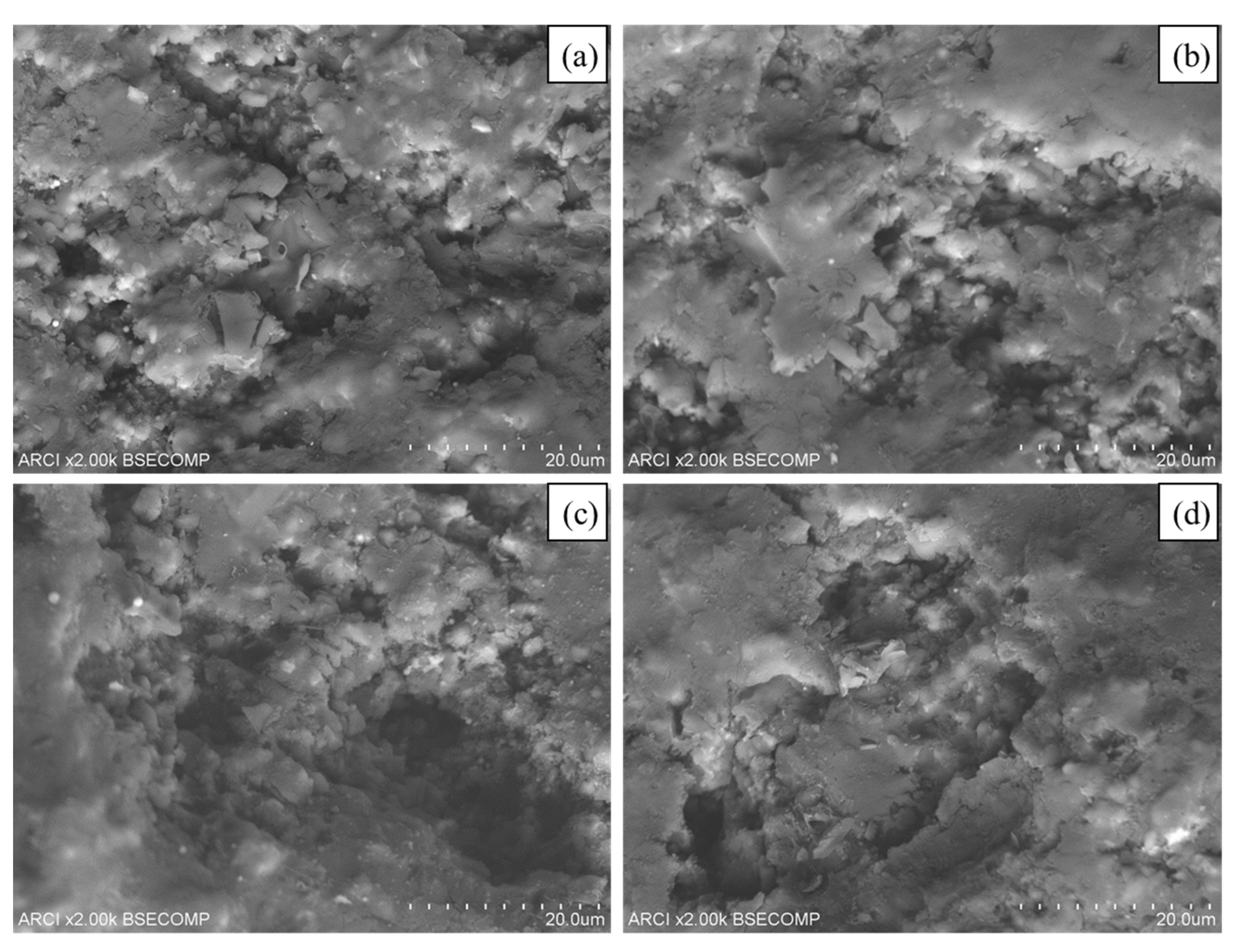
3.1. Surface Morphology
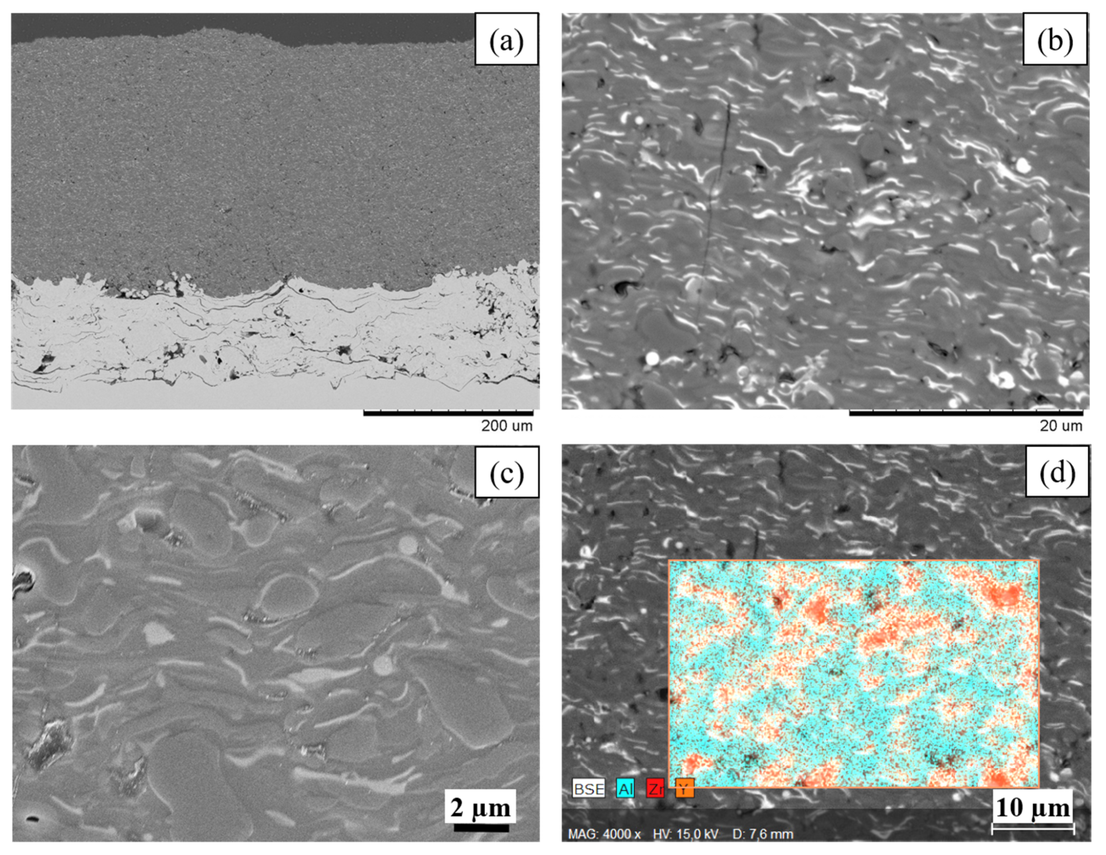
The typical as-deposited surface morphology of the axial suspension plasma sprayed Al2O3-YSZ coatings is presented in Figure 3. The relatively finer splats arising from the deposition of sub-micron sized suspension are evident from the surface micrograph. The micrograph clearly shows homogeneously distributed grey (Al2O3) and white (YSZ) features, for EDS refer Section 3.2. It can be seen from the micrograph that the white regions are finer than the grey splats, which is consistent with the fact that the Al2O3 feedstock powder particles constituting the suspension were approximately 5 times larger than the YSZ particles.

3.2. Microstructure

Cross-sectional micrographs of the mixed suspension coatings recorded in BSE mode are shown in Figure 4a–c. A low-magnification transverse-section micrograph of the Al2O3-YSZ coating is shown in Figure 4a and reveals homogeneously distributed YSZ in the Al2O3 matrix. This was further confirmed through a high magnification micrograph as shown in Figure 4b,c. The predominantly lamellar microstructure corroborates nearly complete melting of both feedstock particles. EDS results obtained using point analysis, shown in Figure 5, reveal that the white regions (Spectrum 2, Figure 5c) correspond to YSZ. It may be pointed out that, due to the extremely small feature size of the YSZ splats, the EDS analysis only shows the white regions as (Y, Zr) rich due to the inevitable simultaneous detection of the predominantly present Al in the adjoining grey regions. It should also be mentioned that an EDS area map shown in Figure 4d revealed no evident “contamination” in the coating and, within the resolution constraints, confirmed a good distribution of the YSZ in the Al2O3 matrix.

3.3. Phase Constitution

XRD pattern of the Al2O3-YSZ powder used to prepare the suspension and the coatings deposited therefrom are depicted in Figure 6. In the graph, some of the peaks have multiple indexing since peaks for gamma (γ) and alpha (α) Al2O3, and tetragonal (t) YSZ were overlapping. The quantitative phase composition analysis clearly indicates the relative amounts of the identified phases. The Rietveld analysis revealed that the starting powder contains a mix of alpha-alumina (80.2%), tetragonal YSZ (19.0%), and monoclinic (m) zirconia (0.8%). The presence of the monoclinic phase in the feedstock material is expected due to the manufacturing route adopted for producing the YSZ sub-micron material, as mechanical milling induces a reversible phase transformation in the YSZ from tetragonal to monoclinic. The phase composition also confirms that the ratio of 80:20 Al2O3/YSZ was achieved in the mixed suspension before plasma spraying.
The XRD pattern of the deposited SPS sample is given in Figure 7. As stated previously, some of the peaks were overlapping and hence left unmarked. The XRD shows the appearance of the gamma phase of alumina (74.4%), which is known to form from high-temperature quenching [36]. The alpha-alumina phase content is found to be reduced to approximately 14.0% of the total. As reported widely for plasma-sprayed YSZ coatings, the as-deposited coatings exhibit a tetragonal phase alone, even though the starting powder had the minor presence of monoclinic ZrO2. The high solidification rates achieved during non-equilibrium plasma spraying of YSZ usually results in metastable t- ZrO2 alone. However, the total content of YSZ is reduced to 11.3% of the total.
The loss in YSZ from the final coating relative to the feedstock may be due to the loss of some portion of the very fine YSZ particles in overspray (non-deposited material) from the plasma jet due to Stoke’s effect for fine-sized particles [37]. Alternatively, some of the YSZ may partially constitute the glassy phase present within the coating.

3.4. Porosity and Hardness

The porosity and micro-hardness of the coating were 3.5 ± 1.2% and 934 ± 42 HV0.1, respectively. The effect of porosity on coating hardness has been previously studied elsewhere [31]. A comparison with results from a previous study by the authors on axial plasma spraying of Al2O3 suspension coatings reveals that there is no significant change in the hardness of the coating after the addition of YSZ. It is also pertinent to note that the hardness may not be the direct indicator of wear resistance and hence, detailed studies on mechanical performance are essential to understand the functionality of these coatings.

3.5. Tribological Behavior

Since the as-sprayed coating exhibited significant surface roughness, the samples were polished prior to conducting two tribological tests to study the behavior of the coating and also to enable comparison with other similar plasma sprayed coatings without the surface asperities being an influencing factor. The results ensuing from three different tribology tests, i.e., scratch, ball-on-disc wear, and dry sand erosion, are discussed below.

3.5.1. Scratch Tests

A surface scratch test on the coating can be considered as a single point abrasive wear test [38]. It essentially involves a diamond stylus scratching the coating at a progressively increasing load to determine the “critical loads” at which fracture within the coating occurs or the coating is detached from the substrate to signify its failure. In the present study, as the coating thickness and the diameter of the stylus tip were of comparable magnitude, detachment of coating from the substrate was not possible. However, the extent and nature of damage in the coating with increasing load were tracked, with an AE sensor also continuously picking up the number of signals from the indenter to aid in the assessment of cohesive strength between successive splats. The analysis of the test also involved a qualitative comparison of the scratch track width (observed through an optical microscope) with increasing load, which can be correlated with the cohesive strength of the coatings.
Figure 8 shows the OM images of scratches at intermediate normal loads. With an increase in normal load, the edges of the scratch track clearly show increasing damage in the form of larger pull-outs from the coating. One plausible reason for such pull-outs can be initiation and subsequent propagations of cracks in the coating due to an increase in tensile stresses induced by the motion of the scratch tip with increasing load [39]. This crack propagation could cause the linking of pores which could lead to detachment of the material from the coating. This microscopic observation is also supported by the increasing intensity of acoustic emission signals with an increasing normal load on the coating, as shown in Figure 9.
A closer examination of the scratch and the acoustic emission signal reveals that the critical load corresponding to the onset of noticeable damage in the coating is around 75–80 N for these Al2O3-YSZ coatings. It may also be noted that, at loads beyond the above-mentioned critical load, local regions with more pull-outs in the vicinity of the scratch are observed. Such an instantaneous increase in scratch width can be caused not only by local defects such as pores but are also attributable to the accumulation of stresses and their relief upon cracking. This is also apparent from the sudden rise and fall in the intensity of acoustic emission signals (Figure 9). The effect of internal stress and cracking on acoustic emission signals has been previously reported [40]. The observed instantaneous change in intensity of signals, together with the sizes of the fractured areas, reveals that the cohesion of the coating is high. If cohesion was low, the damages would be much smaller, correlated to the splat sizes, and located very close to the track.

3.5.2. Ball-on-Disc Wear Tests

Figure 10 shows the measured friction coefficient µ during dry sliding for two different loads. Three distinct regions are identified in the plotted graph. The first and third regions are called running-in and stabilization regimes. In the running-in regime, the friction coefficient increases rapidly because of particle generation between the mating surfaces. Thereafter, lowering of friction coefficient could be due to filling up of pores by the wear debris at a very fine scale before the system reaches a steady-state, known as a stabilization regime. The estimation of the friction coefficient value corresponds to the stabilization regime. It can be seen from the figure that the friction coefficient of the coating was ~0.45, regardless of the applied load. A comparison with the friction coefficient of pure Al2O3 suspension based coating ~0.61, previously reported by the authors [32], reveals the lowering of friction coefficient with the addition of YSZ. In the case of APS Al2O3 coating, the addition of nano-sized YSZ has been to reduce the friction coefficient of the coating [30]. Apart from the use of YSZ material, the addition of TiO2 has also been shown to reduce the friction coefficient of Al2O3 suspension based coating [41].
The wear rates for the two conditions tested are listed in Table 3 and the wear tracks are visualized in Figure 11. The mean worn area used for calculation of wear rate is the area of the cross-sectional profile of the wear track, below the original unaffected coating surface. The stated depth is the average of the maximum depth of the wear track measured at two diametrically opposite locations of the track. The wear rate of SPS Al2O3 previously reported by the authors [32] was significantly higher than that of the composite Al2O3-YSZ coating investigated in the present study (~4 × 10⁻⁵ mm3 N−1 m−1 as compared to ~1.45 × 10⁻⁵ mm3 N−1 m−1 at 10 N load). The presence of the metastable tetragonal-ZrO2 phase is known for its enhanced wear resistance characteristics due to higher fracture toughness [42]. The above results reflect the improvement in wear behavior of Al2O3 by the addition of YSZ, both in terms of friction coefficient and wear loss. It is also pertinent to point out that the previous study had already shown the refined microstructure enabled by SPS Al2O3 to yield much better properties than the usual plasma-sprayed Al2O3 coatings deposited using conventional spray grade powder. The above result provides ample added incentive for conveniently utilizing mixed suspensions to achieve further property enhancement.

3.5.3. Erosion Tests

The potential applicability of mixed suspension coatings for erosion resistance applications is exciting because of the inherent design of the coating microstructure. The erosion rate of thermally sprayed coatings, in general, is influenced by many factors such as porosity, the lamellar interface bonding ratio, splat boundaries, relative hardness, etc. [43,44,45]. Although the suspension-based coatings are known for their plentiful splat boundaries, the higher inter-splat bonding (as reflected in the scratch testing results) promises to yield better resistance to the impacting erodent compared to conventional micron-sized powder sprayed counterparts. As observed in Figure 4 and Figure 5, the distributed presence of sub-micron and nano-sized tetragonal-ZrO2 within the Al2O3 matrix is expected to toughen the microstructure, which in turn bears the promise to improve erosion performance.
The ratio of erosion rates at impact angles of 90° and 30°, E90/E30, is an indicator of the nature of erosion, with values less than 0.5 being suggestive of ductile behavior and values greater than 1 implying brittle behavior [46,47]. Compared to pure Al2O3 coatings which are known to exhibit E90/E30 ratio greater than 2 [22], the E90/E30 values for the SPS Al2O3-YSZ coatings were found to be in the range of 1.2–1.4. This indicates the lower degree of brittle deformation in the coating by virtue of the reinforcement provided by YSZ. The lower material removal intensity at 30° and greater intensity of damage at 90° can be seen from Figure 12; the unit of erosion wear rate is g per g erodent. It has been reported in the literature that hard and brittle coatings perform better at low impact angles and maximum wear rate is reached at a 90° angle [48]. The slightly higher relative hardness of the coating (9 GPa, refer Section 3.4) compared to the erodent silica particles (8 GPa) can also be a determining factor and could have contributed to its reduced impairment due to erosion damage. Notwithstanding the prevailing damage mechanisms that require a more elaborate investigation, the above studies do provide ample evidence that the composite Al2O3-YSZ coating can provide better erosion resistance than pure alumina ceramic coatings by virtue of the reinforcement provided by the distributed YSZ in the Al2O3 matrix.
The investigation of eroded surfaces (after 30 min of erosion) can provide insights into the erosion mechanism. The damage caused to the individual splats can be seen at a 30° impact (Figure 13a,b), resulting in lower material removal compared to complete removal of splats at a 90° impact (Figure 13c,d).
In summary, this study has demonstrated the ease of mixing two independent suspensions (of Al2O3 and YSZ, in this case) to conveniently realize “composite” coatings. It was observed that, by virtue of employing axial feeding of the suspension feedstock into the plasma plume, stand-off distances significantly greater than those reported earlier in case of SPS Al2O3-YSZ coatings deposited via radial feeding are possible, i.e., 100 mm in the present work compared to 30 mm for radial feeding previously employed for such coatings [18]. Moreover, due to improved thermal energy transport possible in case of axial feeding compared to radial feeding, a much higher feed rate could be deployed in this study (3.4 kg∙h−1 of a 40 wt.% solid load suspension, corresponding to 1.36 kg∙h−1 of Al2O3-YSZ compared to 2.9 kg∙h−1 of a 25 wt.% solid load suspension which represents less than 0.75 kg∙h−1 of injected powder [18]). In this context, it is also worth mentioning that another earlier reported work even on axial SPS employed a feed rate of only up to 1.8 kg∙h−1 for a suspension with solid loading similar to that used herein. The feed rates employed in this study also surpass by more than a factor of five, the 0.24 kg∙h−1 feed rate employed in APS deposition of a similar coating. Further comparison of the axial SPS deposited Al2O3-YSZ coatings with the conventional powder-derived APS coatings revealed significantly lower porosity in the present case compared to the latter [30]. The typical values of coating porosity observed in the present study and other reported SPS coatings is 1–4 vol.% [31], whereas APS spraying resulted in 20 vol.% porosity [30]. For tribological applications, for which these composite coatings are commonly considered, the processing and economic benefits suggested by the present study are significant and also supported by good wear properties.

4. Conclusions

The present study deals with the preparation of a mixed Al2O3-20 wt.% YSZ suspension, its deposition using axial plasma spraying, characterization of resulting coatings, and evaluation of their tribological behavior employing diverse wear tests. It demonstrates that mixed suspensions with distinct ceramic constituents can be successfully prepared for plasma spraying. A suitable processing window enables the deposition of dense, finely structured coatings with uniform distribution of YSZ in an Al2O3 matrix. Scratch testing reveals good inter-splat cohesion. The presence of distributed YSZ in the Al2O3 coatings leads to a lowering of friction coefficient and improvement in wear resistance of the coating. The erosion test, too, reveals a lower degree of brittle deformation in the coating by virtue of the reinforcement provided by YSZ.

Author Contributions

S.G. (Sneha Goel) performed a majority of all the experimental investigations, analyzed all the results, and wrote the initial draft of the paper; S.B. was involved in the planning of experiments and carried out all the spraying work; N.C. was involved in planning formulation of the suspension feedstock and analysis of the results; S.G. (Sivakumar Govindarajan) carried out the erosion tests; U.W. planned the scratch and sliding wear tests, and also analyzed the ensuing results; C.G. carried out the EDS analysis; S.J. contributed in defining the problem, planning the experimental approach, reviewing analysis of the results and the manuscript. All authors discussed the results and finalized the paper. All authors have read and agreed to the published version of the manuscript.

Funding

This research received no external funding.

Acknowledgments

The authors are grateful to Kenneth Andersson for his guidance during metallographic sample preparation. The contributions of Ashish Ganvir during porosity evaluation, Adwait Jahagirdar in performing profilometry and Ernst Hinteregger (Treibacher Industrie AG) in carrying out XRD analysis are also gratefully acknowledged. Thanks to Antonio Ancona for assistance in EDS analysis at the University of Bari.

Conflicts of Interest

The authors declare no conflict of interest.

References

  1. Chen, D.; Jordan, E.H.; Gell, M. Microstructure of suspension plasma spray and air plasma spray Al2O3-ZrO2 composite coatings. J. Therm. Spray Technol. 2009, 18, 421–426. [Google Scholar] [CrossRef]
  2. Gupta, M. Design of Thermal Barrier Coatings: A Modelling Approach. Ph.D. Thesis, University West, Trollhättan, Sweden, 2015. [Google Scholar]
  3. Zois, D.; Lekatou, A.; Vardavoulias, M.; Panagiotopoulos, I.; Vazdirvanidis, A. A comparative microstructural investigation of nanostructured and conventional Al2O3 coatings deposited by plasma spraying. J. Therm. Spray Technol. 2008, 17, 887–894. [Google Scholar] [CrossRef]
  4. Kumar, V.; Kandasubramanian, B. Processing and design methodologies for advanced and novel thermal barrier coatings for engineering applications. Particuology 2016, 27, 1–28. [Google Scholar] [CrossRef]
  5. Lima, R.S.; Marple, B.R. Thermal spray coatings engineered from nanostructured ceramic agglomerated powders for structural, thermal barrier and biomedical application. J. Therm. Spray Technol. 2007, 16, 40–63. [Google Scholar] [CrossRef] [Green Version]
  6. Ganvir, A.; Curry, N.; Björklund, S.; Markocsan, N.; Nylén, P. Characterization of microstructure and thermal properties of YSZ coatings obtained by axial suspension plasma spraying (ASPS). J. Therm. Spray Technol. 2015, 24, 1195–1204. [Google Scholar] [CrossRef]
  7. Xia, W.-S.; Yang, Y.-Z.; Zhang, H.-O.; Wang, G.-L. Fabrication and electrochemical performance of solid oxide fuel cell components by atmospheric and suspension plasma spray. Trans. Nonferrous Met. Soc. China 2009, 19, 1539–1544. [Google Scholar] [CrossRef]
  8. Toma, F.-L.; Berger, L.-M.; Scheitz, S.; Langner, S.; Rödel, C.; Potthoff, A.; Sauchuk, V.; Kusnezoff, M. Comparison of the microstructural characteristics and electrical properties of thermally sprayed Al2O3 coatings from aqueous suspensions and feedstock powders. J. Therm. Spray Technol. 2012, 21, 480–488. [Google Scholar] [CrossRef] [Green Version]
  9. Sathish, S.; Geetha, M.; Aruna, S.T.T.; Balaji, N.; Rajam, K.S.S.; Asokamani, R. Sliding wear behavior of plasma sprayed nanoceramic coatings for biomedical applications. Wear 2011, 271, 934–941. [Google Scholar] [CrossRef]
  10. Fauchais, P.; Etchart-Salas, R.; Rat, V.; Coudert, J.F.F.; Caron, N.; Wittmann-Ténèze, K. Parameters controlling liquid plasma spraying: Solutions, sols, or suspensions. J. Therm. Spray Technol. 2008, 17, 31–59. [Google Scholar] [CrossRef]
  11. Bacciochini, A.; Montavon, G.; Ilavsky, J.; Denoirjean, A.; Fauchais, P. Porous architecture of SPS thick YSZ coatings structured at the nanometer scale (∼50 nm). J. Therm. Spray Technol. 2010, 19, 198–206. [Google Scholar] [CrossRef]
  12. VanEvery, K.; Krane, M.J.M.; Trice, R.W.; Wang, H.; Porter, W.; Besser, M.; Sordelet, D.; Ilavsky, J.; Almer, J. Column formation in suspension plasma-sprayed coatings and resultant thermal properties. J. Therm. Spray Technol. 2011, 20, 817–828. [Google Scholar] [CrossRef] [Green Version]
  13. Kassner, H.; Siegert, R.; Hathiramani, D.; Vassen, R.; Stoever, D. Application of suspension plasma spraying (SPS) for manufacture of ceramic coatings. J. Therm. Spray Technol. 2008, 17, 115–123. [Google Scholar] [CrossRef]
  14. Ganvir, A.; Curry, N.; Markocsan, N.; Nylén, P.; Toma, F.L. Comparative study of suspension plasma sprayed and suspension high velocity oxy-fuel sprayed YSZ thermal barrier coatings. Surf. Coat. Technol. 2015, 268, 70–76. [Google Scholar] [CrossRef]
  15. Ganvir, A.; Curry, N.; Govindarajan, S.; Markocsan, N. Characterization of thermal barrier coatings produced by various thermal spray techniques using solid powder, suspension, and solution precursor feedstock material. Int. J. Appl. Ceram. Technol. 2016, 13, 324–332. [Google Scholar] [CrossRef]
  16. Curry, N.; VanEvery, K.; Snyder, T.; Susnjar, J.; Bjorklund, S. Performance testing of suspension plasma sprayed thermal barrier coatings produced with varied suspension parameters. Coatings 2015, 5, 338–356. [Google Scholar] [CrossRef] [Green Version]
  17. Fauchais, P.; Etchart-Salas, R.; Delbos, C.; Tognonvi, M.; Rat, V.; Coudert, J.F.; Chartier, T. Suspension and solution plasma spraying of finely structured layers: Potential application to SOFCs. J. Phys. D Appl. Phys. 2007, 40, 2394–2406. [Google Scholar] [CrossRef]
  18. Tingaud, O.; Bertrand, P.; Bertrand, G. Microstructure and tribological behavior of suspension plasma sprayed Al2O3 and Al2O3-YSZ composite coatings. Surf. Coat. Technol. 2010, 205, 1004–1008. [Google Scholar] [CrossRef]
  19. Bouyer, E.; Gitzhofer, F.; Boulos, M.I. The suspension plasma spraying of bioceramics by induction plasma. J. Manag. 1997, 49, 58–62. [Google Scholar] [CrossRef]
  20. Bolelli, G.; Bellucci, D.; Cannillo, V.; Lusvarghi, L.; Sola, A.; Stiegler, N.; Müller, P.; Killinger, A.; Gadow, R.; Altomare, L.; et al. Suspension thermal spraying of hydroxyapatite: Microstructure and in vitro behaviour. Mater. Sci. Eng. C 2014, 34, 287–303. [Google Scholar] [CrossRef]
  21. Znamirowski, Z.; Czarczynski, W.; Le Maguer, A.; Pawlowski, L. Plasma sprayed and laser engraved field electron emitters. Surf. Coat. Technol. 2003, 165, 211–215. [Google Scholar] [CrossRef]
  22. Matikainen, V.; Niemi, K.; Koivuluoto, H.; Vuoristo, P. Abrasion, erosion and cavitation erosion wear properties of thermally sprayed alumina based coatings. Coatings 2014, 4, 18–36. [Google Scholar] [CrossRef] [Green Version]
  23. Oberste Berghaus, J.; Legoux, J.G.; Moreau, C.; Tarasi, F.; Chráska, T. Mechanical and thermal transport properties of suspension thermal-sprayed alumina-zirconia composite coatings. J. Therm. Spray Technol. 2008, 17, 91–104. [Google Scholar] [CrossRef]
  24. Tarasi, F.; Medraj, M.; Dolatabadi, A.; Oberste-Berghaus, J.; Moreau, C. Amorphous and crystalline phase formation during suspension plasma spraying of the alumina-zirconia composite. J. Eur. Ceram. Soc. 2011, 31, 2903–2913. [Google Scholar] [CrossRef] [Green Version]
  25. Björklund, S.; Goel, S.; Joshi, S. Function-dependent coating architectures by hybrid powder-suspension plasma spraying: Injector design, processing and concept validation. Mater. Des. 2018, 142, 56–65. [Google Scholar] [CrossRef]
  26. Murray, J.W.; Leva, A.; Joshi, S.; Hussain, T. Microstructure and wear behaviour of powder and suspension hybrid Al2O3–YSZ coatings. Ceram. Int. 2018, 44, 8498–8504. [Google Scholar] [CrossRef]
  27. Chevalier, J.; De Aza, A.H.; Fantozzi, G.; Schehl, M.; Torrecillas, R. Extending the lifetime of ceramic orthopaedic implants. Adv. Mater. 2000, 12, 1619–1621. [Google Scholar] [CrossRef]
  28. Kern, F.; Palmero, P. Microstructure and mechanical properties of alumina 5vol% zirconia nanocomposites prepared by powder coating and powder mixing routes. Ceram. Int. 2013, 39, 673–682. [Google Scholar] [CrossRef]
  29. Mangalaraja, R.V.; Chandrasekhar, B.K.; Manohar, P. Effect of ceria on the physical, mechanical and thermal properties of yttria stabilized zirconia toughened alumina. Mater. Sci. Eng. A 2003, 343, 71–75. [Google Scholar] [CrossRef]
  30. Dejang, N.; Limpichaipanit, A.; Watcharapasorn, A.; Wirojanupatump, S.; Niranatlumpong, P.; Jiansirisomboon, S. Fabrication and properties of plasma-sprayed Al2O3/ZrO2 composite coatings. J. Therm. Spray Technol. 2011, 20, 1259–1268. [Google Scholar] [CrossRef]
  31. Tarasi, F. Suspension Plasma Sprayed Alumina-Yttria Stabilized Zirconia Nano-Composite Thermal Barrier Coatings—Formation and Roles of the Amorphous Phase. Ph.D. Thesis, Concordia University, Montreal, QC, Canada, 2010. [Google Scholar]
  32. Goel, S.; Björklund, S.; Curry, N.; Wiklund, U.; Joshi, S.V. Axial suspension plasma spraying of Al2O3 coatings for superior tribological properties. Surf. Coat. Technol. 2017, 315, 80–87. [Google Scholar] [CrossRef]
  33. Xie, Y.; Hawthorne, H.M. The damage mechanisms of several plasma-sprayed ceramic coatings in controlled scratching. Wear 1999, 233, 293–305. [Google Scholar] [CrossRef]
  34. Lamuta, C.; Di Girolamo, G.; Pagnotta, L. Microstructural, mechanical and tribological properties of nanostructured YSZ coatings produced with different APS process parameters. Ceram. Int. 2015, 41, 8904–8914. [Google Scholar] [CrossRef]
  35. Darut, G.; Ben-Ettouil, F.; Denoirjean, A.; Montavon, G.; Ageorges, H.; Fauchais, P. Dry sliding behavior of sub-micrometer-sized suspension plasma sprayed ceramic oxide coatings. J. Therm. Spray Technol. 2010, 19, 275–285. [Google Scholar] [CrossRef]
  36. McPherson, R. Formation of metastable phases in flame- and plasma-prepared alumina. J. Mater. Sci. 1973, 8, 851–858. [Google Scholar] [CrossRef]
  37. Fauchais, P.L.; Heberlein, J.V.; Boulos, M.I. Thermal Spray Fundamentals: From Powder to Part; Springer: New York, NY, USA, 2014; ISBN 9780387689913. [Google Scholar]
  38. Erickson, L.C.; Hawthorne, H.M.; Troczynski, T. Correlations between microstructural parameters, micromechanical properties and wear resistance of plasma sprayed ceramic coatings. Wear 2001, 250, 569–575. [Google Scholar] [CrossRef]
  39. Erickson, L.C.; Westergård, R.; Wiklund, U.; Axén, N.; Hawthorne, H.M.; Hogmark, S. Cohesion in plasma-sprayed coatings—A comparison between evaluation methods. Wear 1998, 214, 30–37. [Google Scholar] [CrossRef]
  40. Yamamoto, S.; Ichimura, H. Effects of intrinsic properties of TiN coatings on acoustic emission behavior at scratch test. J. Mater. Res. 1992, 7, 2240–2247. [Google Scholar] [CrossRef]
  41. Klyatskina, E.; Espinosa-Fernández, L.; Darut, G.; Segovia, F.; Salvador, M.D.; Montavon, G.; Agorges, H. Sliding wear behavior of Al2O3-TiO2 coatings fabricated by the suspension plasma spraying technique. Tribol. Lett. 2015, 59, 1–9. [Google Scholar] [CrossRef]
  42. Aruna, S.T.; Balaji, N.; Rajam, K.S. Phase transformation and wear studies of plasma sprayed yttria stabilized zirconia coatings containing various mol% of yttria. Mater. Charact. 2011, 62, 697–705. [Google Scholar] [CrossRef]
  43. Branco, J.R.T.; Gansert, R.; Sampath, S.; Berndt, C.C.; Herman, H. Solid particle erosion of plasma sprayed ceramic coatings. Mater. Res. 2004, 7, 147–153. [Google Scholar] [CrossRef] [Green Version]
  44. Li, C.-J.J.; Yang, G.-J.J.; Ohmori, A. Relationship between particle erosion and lamellar microstructure for plasma-sprayed alumina coatings. Wear 2006, 260, 1166–1172. [Google Scholar] [CrossRef]
  45. Harsha, S.; Dwivedi, D.K.; Agarwal, A. Influence of CrC addition in Ni-Cr-Si-B flame sprayed coatings on microstructure, microhardness and wear behaviour. Int. J. Adv. Manuf. Technol. 2008, 38, 93–101. [Google Scholar] [CrossRef]
  46. Roy, M.; Ray, K.K.; Sundararajan, G. Erosion-oxidation interaction in Ni and Ni-20Cr alloy. Metall. Mater. Trans. A 2001, 32, 1431–1451. [Google Scholar] [CrossRef]
  47. Katsich, C.; Badisch, E.; Roy, M.; Heath, G.R.R.; Franek, F. Erosive wear of hardfaced Fe-Cr-C alloys at elevated temperature. Wear 2009, 267, 1856–1864. [Google Scholar] [CrossRef]
  48. Blau, P.J. ASM Handbook, Volume 18-Friction, Lubrication, and Wear Technology; Blau, P.J., Ed.; ASM International: Materials Park, OH, USA, 1992; ISBN 9780871703804. [Google Scholar]
Figure 1. Schematic of axial and radial feeding of feedstock.
Applsci 10 05140 g001
Figure 2. Morphologies of (a) Al2O3 (reproduced with permission from [32], Elsevier, 2017), and (b) YSZ powder constituting the mixed suspension.
Applsci 10 05140 g002
Figure 3. Surface morphology of the axial suspension plasma sprayed Al2O3-YSZ coating showing the YSZ (white regions) well distributed along with Al2O3 (grey regions).
Applsci 10 05140 g003
Figure 4. Cross-section of the SPS Al2O3-YSZ coating at (a) low and (b), (c) high-magnification, and (d) a typical Electron Dispersive Spectroscopy (EDS) area map showing elemental distribution.
Applsci 10 05140 g004
Figure 5. EDS analysis of the SPS Al2O3-YSZ coating depicted in (a); the spectrum from the grey matrix in (b) suggests predominance of Al2O3 while that from the white fringes in (c) exhibits higher YSZ concentration. The accelerating voltage of electrons was 17 kV and the aperture size 30 µm.
Applsci 10 05140 g005
Figure 6. XRD pattern of Al2O3-YSZ dried mixed suspension powder with Cu Kα radiation.
Applsci 10 05140 g006
Figure 7. XRD pattern of the SPS Al2O3-YSZ coating with Cu Kα radiation.
Applsci 10 05140 g007
Figure 8. Optical microscope images of the residual scratch track on the SPS Al2O3-YSZ coating. The normal load in Newton (N) is indicated and the arrow depicts the scratch direction.
Applsci 10 05140 g008
Figure 9. Acoustic emission signal from the SPS Al2O3-YSZ coating during the scratch test.
Applsci 10 05140 g009
Figure 10. Friction coefficient evolution with sliding distance for different applied loads during ball-on-disc wear testing of SPS Al2O3-YSZ coating.
Applsci 10 05140 g010
Figure 11. Optical profilometry images of wear tracks resulting from ball-on-disc tests carried out at two different loads of 10 N and 20 N, along with corresponding cross-sectional profiles measured along the black dashed lines.
Applsci 10 05140 g011
Figure 12. The erosion wear rate of SPS Al2O3-YSZ coating (g∙g−1 of erodent).
Applsci 10 05140 g012
Figure 13. Surface morphologies of Al2O3-YSZ coatings after erosion studies at (a) 30° impact at 48 m∙s−1, (b) 30° impact at 108 m∙s−1, (c) 90° impact at 48 m∙s−1, and (d) 90° impact at 108 m∙s−1.
Applsci 10 05140 g013
Table 1. Spray parameters employed for coating deposition.
Plasma Spray ParametersValue
Operating gases, vol.%Ar, N2, H2 (45,45,10)
Gas flow rate, L∙min−1220
Spray Distance, mm100
Current, A220
Suspension feed rate, mL∙min−140
Power, kW122
Number of passes16
Table 2. Erosive wear test conditions.
NomenclatureValue
ErodentSilica
Erodent particle size, μm190–210
Particle velocity, ms−148, 108
Erodent feed rate, g min−14.5
Duration of each run, min1
Total number of runsRepeated until steady state
Erodent impact angle, °30, 90
Nozzle to sample distance, mm10
Test temperature, °C32 ± 5
Table 3. Depth, worn cross-section area, and wear rate of the coatings.
Load
(N)
<Depth>
(µm)
<Area>
(µm2)
Wear Rate
(10−5 mm3 N−1 m−1)
103.514501.45
20533001.65

