Article

Layer-by-Layer Deposition of Copper and Phosphorus Compounds to Develop Flame-Retardant Polyamide 6/Montmorillonite Hybrid Composites

Department of Chemistry and Technology of Polymers, Cracow University of Technology, ul. Warszawska 24, 31-155 Kraków, Poland
*
Author to whom correspondence should be addressed.
Appl. Sci. 2020, 10(14), 5007; https://doi.org/10.3390/app10145007
Submission received: 26 June 2020 / Revised: 14 July 2020 / Accepted: 17 July 2020 / Published: 21 July 2020
(This article belongs to the Special Issue Synthesis, Characterization and Application of Hybrid Composites)

Abstract

:
Nowadays, increasing attention is devoted to the search for polymeric composite materials that are characterized by reduced flammability. In this work, the layer-by-layer (LbL) technique was applied to form multilayered protective coatings for polyamide 6/montmorillonite (PA6/MMT) hybrid nanocomposites. This time, the double layers LbL deposition was used in order to improve the thermal properties or flammability of PA6 materials. Our goal was to check how five, 10, and 15 triple-layer deposition onto the surface of PA6 and PA6/MMT composites influenced these relevant properties. For this reason, disodium H-phosphonate, sodium montmorillonite, and iodo-bis(triphenylphosphino)copper were used for polyelectrolyte solution preparation. It was found that the LbL method could be successfully used to improve the flammability characteristics of polyamide 6-based composites. Nevertheless, the deposition of the copper complex should be combined with other flame retardants—preferentially containing phosphorus—which enable synergistic effects to occur. Moreover, microscopic observations confirmed that the surfaces on which the formation of interwoven fibrous crystal structures was observed had a tendency to protect the entire material against the destructive effects of heat, contributing, among other things, to reduce the maximum point of heat release rate (PHRR).

Graphical Abstract

1. Introduction

Due to its interesting properties, such as high mechanical strength, chemical resistance, high abrasion, spinnability, and low thermal expansion, polyamide 6 is one of the most important thermoplastic polymers, widely used as a constructive material [1,2]. The main limitation of polyamide 6 (PA6) applications is its flammability. Among different methods to reduce PA6 flammability, the application of nanoparticles, such as layered silicates, has been reported as an efficient route toward flame-retarded polyamide composites [3]. The use of nanoparticles is also beneficial from the viewpoint of enhanced mechanical, thermal, and barrier properties [3,4].
In order to improve the flame retardancy of polyamides, novel compounds are used in composite materials. He et al. obtained composites of polyamide 6 and aluminum diisobutylphosphinate (APBA), combined with organically modified layered montmorillonite (OMMT) by melt compounding. The results showed synergy between these two compounds in terms of flame retardancy; the highest value of limiting oxygen index (LOI)—36%, was obtained for the sample with a ratio for APBA and OMMT of 5:1 [3,5]. Liu et al. investigated the influence of caged bicyclic pentaerythritol phosphate alcohol (PEPA) on the flame-retardant properties of PA6. The results showed that the LOI values of composites increased with increasing PEPA content [6]. Other compounds which have been recently investigated to reduce the flammability of PA6 were phosphorous–nitrogen flame-retardant and platelet-shaped hexagonal boron nitride. The incorporation of those compounds into polyamide allows the application of the final product in electronic and electrical devices [7]. Moreover, char sulfonic acid and ammonium polyphosphate, metal oxalates, brominated polystyrene/antimony trioxide, or red phosphorus/magnesium hydroxide systems have been applied to reduce the flammability of polyamides [8,9,10,11,12,13].
The layer-by-layer (LbL) deposition technique offers a direct way to form flame-retardant coatings on the polymers’ surface [14,15]. LbL involves applying layers via the immersion of the substrate, alternately in solutions containing positively and negatively charged moieties. The absorption of layers occurs mainly through electrostatic interactions, though other interactions, i.e., the formation of covalent bonds, hydrogen bonding, donor/acceptor interactions, and the formation of stereo-complexes are also possible [16,17]. Considering the traditional approach to incorporating flame retardants in polymer matrices, the application of the LbL technique may prove advantageous. Firstly, it diminishes problems related to the introduction of flame retardants into the matrix. Secondly, as the flame affects the exterior part of the substrate, the presence of layers containing flame retardants may directly impact the combustion process [16]. Recent reports on PA6 flame retardancy improvements using LbL include the coating of polyamide with poly(allylamine) and montmorillonite [15], poly(allylamine) with sodium polyphosphate and titanium(IV) oxide [18,19], anionic sodium phosphate and cationic polysiloxanes [20], chitosan, phytic acid and oxidized sodium alginate [21] with additional cross-linking between the layers by the introduction of sodium tetraborate [22] or chitosan and montmorillonite [23].
In other work [24], membranes with a polyamide thin-film active layer were used in reverse osmosis-based water desalination applications. The incorporation of graphene oxide nanoplatelets in the polyamide layer can alter the surface characteristics, permeability, selectivity, and can enhance the chlorine resistance of these membranes. Polyamide layers with graphene oxide nanoplatelets were synthesized in various sequences. The incorporation of graphene oxide nanoplatelets resulted in an increase in surface hydrophilicity as captured by the change of the water contact angle. Water flux and salt rejection properties of the synthesized membranes have been investigated by using a dead-end cell. The salt rejection ability of membranes increased slightly with the incorporation of GONPs, while the water flux was found to be similar to that observed for the pristine membranes without graphene oxide nanoplatelets.
In the latest works, [25] the layer-by-layer (LBL) deposition of chitosan/melamine/urea and phytic acid onto the acrylic acid-grafted polyamide fabrics, including a pad-dry-cure treatment with chitosan/graphene oxide nanocomposites, was considered to improve the hydrophilicity and durable flame retardancy. The obtained results indicated that these hybrid coatings could significantly improve the flame retardancy as the limiting oxygen index value went up to 25% from 18.5% and could completely stop the melt dripping where the fabric sample with two bilayer deposition and simultaneously treated with chitosan/graphene oxide nanocomposite achieved a V-1 rating. Moreover, a considerable improvement in the thermal stability and char yield was also realized in the thermogravimetric analysis test. Furthermore, the as-prepared hybrid coatings imparted better hydrophilicity as a two bilayer deposition along with a pad-dry-cure treatment by the chitosan/graphene oxide system could boost up the hydrophilicity of the treated fabrics further compared to the only two bilayer deposited fabric sample.
In the work [26], also chitosan and phosphorylated chitosan were deposited onto the polyamide fabric surfaces along with poly-acrylate sodium, via one-pot and layer-by-layer assembly methods in preparing flame-retardant coatings. Subsequently, to stabilize the deposited coatings, some of the fabric samples were treated under UV irradiation, and additionally, a thermal treatment was also carried out for the remaining fabric samples. The LbL assembled fabrics showed a better homogeneity in the coating structure over the one-pot deposited fabrics than as appeared in scanning electron microscopy. Nonetheless, the LbL-treated fabric sample with a higher weight gain% exhibited a greater improvement in the limiting oxygen index, and a reduced peak heat release rate.
Similarly, in Ref. [27], chitosan and phytic acid, along with a sol–gel treatment from (3-aminopropyl) triethoxysilane and boron-doped APTES sol solutions, was followed in constructing a flame-retardant and hydrophilic coating onto polyamide fabric surfaces. Layer-by-layer assembled and simultaneously sol–gel-treated PA fabric samples could be able to stop the melt-dripping in a vertical burning test. The boron-doped APTES sol-treated fabric samples with a 2–5 bilayer deposition showed a reduced peak heat release rate in the cone calorimetry test and revealed an improved thermal stability in the thermogravimetric analysis test. More interestingly, the boron-doped silica sol could significantly increase the hydrophilicity of the treated fabrics compared to only LbL and simultaneously LbL-deposited and silica sol-treated fabric samples.
The obtained results reveal that the LbL technique can be successfully used to deposit coatings providing a better flame retardancy of the polyamide matrices [25,26,27,28].
In this work, polyamide 6 nanocomposites with MMT were surface modified via the layer-by-layer deposition of copper and phosphorus compounds. The influence of the deposition technique on the thermal properties and flammability of the surface-modified hybrid materials was examined and discussed.

2. Materials and Methods

2.1. Materials

Tarnamid® T-27 polyamide 6 (PA6) in the form of pellets was obtained from Grupa Azoty S.A. (Tarnów, Poland). It is a medium viscosity type of polymer, designed for the processing of modified pellets by compounding methods.
Cloisite® 20A (BYK Additives&Instruments, Wesel, Germany) montmorillonite (MMT), organophilized with 125 meq/100 g quaternary ammonium salt chloride (composed of ~65% C18, ~30% C16, ~5% C14 mixture of aliphatic chains), was used to prepare the PA6 nanocomposite (REFMMT).
For the ionic solutions’ preparation, sodium montmorillonite (MMT-Na+) (Dellite® LVF, Laviosa Chimica Mineraria, Livorno, Italy), H-phosphonate (HP) (Sigma-Aldrich, Steinheim, Germany), iodo-bis(triphenylphosphino)copper (CC) (Sigma-Aldrich, Steinheim, Germany), deionized water (DI) (Hipernet, Kraków, Poland), ethyl acetate (EA) (POCH, Gliwice Poland), hydrochloric acid solution (Chempur, Piekary Śląskie, Poland) and 1M sodium hydroxide solution (POCH, Gliwice, Poland) were used.

2.2. Processing Methods

PA6 pellets, vacuum dried at 80 °C for 6 h, and organophilized layered silicate, were mixed in mass proportion 97:3 by the mechanical shaking of a batch in a plastic container for 15 min. Later, the batch was dosed into a twin-screw counter-rotating laboratory extruder Thermo Scientific Haake PolyLab PTW 16/25 to form a nanocomposite with 150 rpm rotation speed. As a dosing device, Brabender DDSR20 feeder compatible with an extruder, working with 45 rpm, was used. During previous tests in our laboratory, this speed had been found as optimal for volumetric dosing, regardless of any screw rotation speed settings. The temperature from the feed end to the die end ranged from 245 to 260 °C. The obtained streak was cooled in a water bath (18 °C) of 1.5 m length and then pelletized. To erase the thermal history, the same procedure was applied to pristine PA6 resin. After one more vacuum drying, two types of materials (REF and REFMMT) were compression molded in a laboratory press ZAMAK P-200 to form 15.0 × 15.0 × 0.3 cm sheets. In addition, 50–55 g of pellets were filled into a mold and pressed at 250 °C under 20 MPa for 2.5 min. The sheets were cooled for 20 min and cut into 15.0 × 1.3 × 0.3 cm bar specimens, that were then used for fire testing.

2.3. Ionic Solutions Preparation

To obtain a 0.5% (m/v) cationic solution, H-phosphonate (HP) was dissolved in 18.2 MΩ deionized water (DI) and a copper complex—iodo-bis(triphenylphosphino)copper (CC), was dissolved in ethyl acetate. Sodium montmorillonite (MMT-Na+) was dispersed in DI at 0.5% (m/v) to form anionic mixtures. All mixtures were magnetically stirred overnight, and after that, the pH of the HP and CC dispersions were adjusted to 4.0 ± 0.5 by adding 1M hydrochloric acid solution or 1M sodium hydroxide solution. The pH of the MMT-Na+ dispersion was 9.8 ± 0.1 (ζ-potential value—45.1 mV, isoelectric point value 1.05).

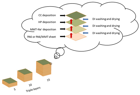
2.4. Layer-by-Layer Deposition (LbL)

Before depositing the LbL assemblies on the pellets, both materials were washed with DI. Bar specimens were additionally immersed into a 10% acetone solution prior to the DI washing and then, either the pellets or bars were vacuum dried at 80 °C for 2 h. All of the specimens were alternatively dipped into the positively and negatively charged solutions: to enhance the adhesion, the first dips in MMT-Na+ (1), HP (3), and CC (5) (Figure 1) were set at 5 min, but subsequent dipping lasted for 1 min.
In the case of pellets, to protect from material loss, specially designed polypropylene sieves, closed from the top by aluminum sieves, were used for the dipping procedure. After each adsorption step, the materials were washed with DI for 1 min in order to desorb the weakly adsorbed surface modification and dried for 30 min at 80 °C. Some part of an excessive amount of water was taken away using tissue paper.
The scheme of the described procedure is shown in Figure 1. Each cycle was repeated until 5, 10 and 15 triple layers (L) were built on each specimen type (for instance, 5L denotes PA6 with 5 triple layers, deposited on the surface of the sample and 10LMMT denotes the PA6/MMT nanocomposite with 10 triple layers deposited by using the LbL technique).

2.5. Thermogravimetric Analysis

The thermogravimetric analysis was performed under the air atmosphere using a Netzsch TG 209 F1 Libra thermogravimetric analyzer. The measurements were conducted in the temperature range from 25 to 600 °C at a heating rate of 10 °C/min, in the synthetic air atmosphere with an airflow rate of 15 cm3/min. Samples of ~5 mg mass were placed in open corundum pans.
In addition, the measurements were carried out in an inert atmosphere in the temperature range from 25 to 600 °C at a heating rate of 1 °C/min, in order to compare the results of the thermal analysis with the measurements made by microscale combustion calorimetry (MCC).

2.6. Flammability Testing

Vertical (VFT) and Horizontal (HFT) flammability tests were performed according to ISO 1210:1992(E) (UL-94) standard using bar specimens. Total burning time and rate of burning (unless the material showed a self-extinguishing effect under specified test conditions) were measured and the digital photographs were taken to depict the characteristics of burning together with residues. Limiting oxygen index (LOI) measurements were performed according to DIN EN ISO 4589-2 using the Concept Fire Testing Oxygen Index Module apparatus that let adjust the concentration of oxygen in a gas stream with 0.1% by volume accuracy. The nitrogen/oxygen mixture rate flow was set at 10 l/min.
The combustion properties were also tested by the means of microscale combustion calorimetry (MCC) according to the ASTM D7309 method A at a synthetic air mixture volume ratio 80/20 (nitrogen/oxygen). The mass of the samples was ca. 5 mg, whereas the heating rate was 1 °C/min.

2.7. Scanning Electron Microscopy (SEM)

For the morphological analysis of the 15L and 15LMMT samples, a Jeol JSM-6010LA scanning electron microscope was used. Pictures of the gold-sputtered samples were obtained at an accelerating voltage of 8–20 kV.

2.8. Surface Roughness and 3D Scanning

The surface roughness profile was tested using a HOMMELWERKE 3D optical profilometer. The basic parameters of roughness were defined in accordance with the PN-87/M-04256/02, PN-87/M-04250, and PN-87/M-04256/01 standards. The measurement for each sample was carried out three times at different places on their surface.
Three-dimensional surface imaging was performed using a Keyence VHX-900F microscope using 100× magnification.

3. Results and Discussion

3.1. Thermogravimetric Analysis

For compositions containing tri-layers deposited with the layer-by-layer method, with the increased number of layers, the temperature of 5% mass loss decreased, independently of the employed substrate (Figure 2). The highest values were observed for the 5L and 5LMMT samples. The thermogravimetry (TG) curves demonstrating the first and the second step of thermal degradation for all samples did not exhibit significant differences.
The analysis of the parameters of thermal degradation showed that in the low-temperature range, the thermal stability decreases with the increase in the number of deposited layers. It was also concluded that the application of any number of layers by the LBL method on the surface of PA6/MMT composites did not affect their thermal stability above 440 °C. The adsorption of five layers on the pure matrix as well as 10 layers on the nanocomposite allowed for obtaining the largest amount of charred residues in comparison to the rest of the analyzed materials (Table 1).
In those materials, a relationship between the decreased mass of the obtained residue and an increase in the number of layers deposited on the surface occurred. Analogously to the results obtained by other research teams [29,30], such results suggest that the application of the triple layers might have a positive impact on the flame retardancy of the pure and filled polyamide matrix, respectively. The barrier effect was particularly pronounced with the application of the least number of deposited layers (5L). The adsorption of the tri-layers on the surface of polyamide materials could reduce the air permeability into the interior of the composite, as a result of which the greater mass of residue in comparison to the reference material was noted. It was concluded that the deposition of layers may have affected the mechanism of thermal degradation of the analyzed compositions, but did not alter the number of steps.
In order to present the influence of the number of deposited tri-layers on the overall thermal stability of the obtained materials, the column graph detailing the values of the additional thermogravimetric index, OSE (overall stabilization effect) (Figure 3), calculated on the basis of the formula (1) given below [31], was created:
OSE = ∑30600(mass% PA6/MMT at T temperature-mass% pure PA6 at T temperature)
The purpose of the OSE index is to assess the materials’ thermal stability in the whole measurement range since its value is determined on the basis of the surface area below the mass loss curve as a function of temperature.
The positive values of the OSE index indicate that all the samples with deposited triple layers are more thermally stable than polyamide 6. The negative value observed for the REFMMT material confirms the existence of the destabilization effect caused by the implementation of the nanofiller in the form of montmorillonite. The best effects were observed after the deposition of five tri-layers via the layer-by-layer method on the surface of the polyamide matrix without reinforcement. Further deposition contributed to a decrease in the value of the OSE index. In the case of the reinforced polymer matrix, the adsorption of tri-layers contributed to the unification of the average effect of thermal stabilization to the value of 1.4%. Thermogravimetric analysis results revealed that the application of the LbL method for the deposition of five triple layers effectively enhances the thermal stability of polyamide materials up to 400 °C.

3.2. Limiting Oxygen Index (LOI)

LOI is defined as the minimum oxygen concentration in the oxygen/air mixture that causes the material to burn. The measurement of the oxygen limit value was started from the reference sample for which 21% was chosen as the reference point [32]. In Table 2, the LOI values obtained for the materials, on which five to 15 triple layers were applied by the LbL method, are presented.
Analyzing the results of the coated polyamide matrices, a decrease in the oxygen index value was observed along with the increase in the number of triple layers applied, regardless of the type of deposition method used. Most likely, this effect was influenced by the way the layers were applied—predominantly on the surface. The application of the LbL method for the adsorption of materials constituting the polyelectrolyte solution and suspensions caused a uniform movement of the flame front towards the holder. The combustion rate for the 5L, 10L, and 15L composites was much smaller than for the reference material.
LOI values for PA6 coated by using the LbL method show no flame-retardant action of the deposited layers. In general, the deposition of triple layers adversely affects the flammability of the pristine polymer matrix.
The incorporation of MMT in an amount of 3% by weight resulted in a decrease in the LOI value by 0.1% compared to pure polyamide 6, which is within the measurement error. The presence of triple layers on the surface of the nanocomposite increased the value of the LOI; the highest LOI improvement was achieved for 15LMMT.
A comparison of the obtained results shows that the use of the LbL method for embedding the HP layers, MMT, and CC on the surface of the PA6 nanocomposite promotes the ignition of the polymeric material. During the combustion of the samples reinforced with MMT, the flame evenly covered the surface, and after its self-extinguishing, no visible smoke appeared, which was observed for the pristine polyamide. This insignificant effect could be related to both the introduction of aluminosilicate into the polyamide matrix, affecting the “closure” of the surface of the incinerated sample by creating a dense protective coating, as well as the depositing of phosphorus and copper compounds on the surface of the PA6/MMT nanocomposite.
The MMT suspension and polyelectrolyte solutions/dispersions introduced into the matrix were most likely thermally decomposed first, resulting in the formation of carbonaceous char preventing the transfer of heat, energy, and oxygen between the flame and the material, thereby reducing the smoke emission and toxic decomposition products [33].

3.3. Vertical (VFT) and Horizontal (HFT) Flammability Tests (UL-94)

Characteristic parameters of the combustion process, carried out using the UL-94 method in horizontal (HB or HFT) and vertical (VB or VFT) mode, are summarized in Table 3 and Table 4. They enable us to qualify the polymer materials obtained into individual flammability classes in accordance with ISO 1210. In the case of a horizontal system, as the initial value of ignition time, the time when the flame reached the beginning of the measurement line, determined by the start line, was considered.
Both reference materials (REF, REFMMT) showed different behavior in the flame during the measurements, however, each of them was completely burned. The incorporation of MMT into the polymer matrix led to a four-fold reduction in the number of detached fragments of the molten material. The reason for this phenomenon can be the reduced mobility of polymer chains in the presence of aluminosilicate packages. During the combustion of the nanocomposite, the formation of a protective barrier was observed in the form of charcoal, resulting from the combustion of dispersed MMT layers in a polyamide matrix. Moreover, in this case, the flame reached a much higher height. The molten parts of the REF and REFMMT materials broke off together with the flame under the influence of the acting force of gravity, nevertheless, the time intervals of the falling fragments of the polyamide matrix were noticeably smaller.
Analyzing the combustion process of the unreinforced polymer matrix coated with triple layers using the LbL method, it was found that an increase in the degree of deposition of solution materials and polyelectrolyte dispersions resulted in an increase in the average combustion rate (Table 3). The consequence of the deposition of the triple layers in the number of ten was the crossing of the starting line by the flame, nevertheless, this material did not completely burn. The main cause of this phenomenon was found in the rapid flame breakdown together with the alloy, interrupting the process of maintaining the heat. In addition, a few seconds before the extinguishing of the material itself, the appearance of air bubbles on the surface of the burning material was observed. In contrast to the REF sample, the detachment of the molten fragments of the composition took place at regular intervals.
The adsorption of triple layers on the surface of the nanocomposite contributed up to about a 38% reduction in the burning time of the 10LMMT composition in relation to the REFMMT material. There was a tendency to increase the average burning time of the materials with an increase in the coverage of the PA6/MMT system. The effect of this dependence was also reducing the average burning rate with the increase in the deposited triple layers. Nevertheless, applying the next five triple layers reduced the burning rate by only one unit.
In order to qualify the obtained composites for individual fire classes, the ISO 1210 standard was applied, according to which the material belongs to the horizontal position (HB) class, when after removing the applied flame, one of the following scenarios occurs:
  • The material does not burn visibly, and the flame front does not reach the measuring line beginning (25 mm); and/or
  • The flame front reaches the entire range of the measuring section (100 mm) at the same time not exceeding the measurement end line; and/or
  • The flame front exceeds the measuring range, and the combustion speed for the samples with a thickness of 3–13 mm is not greater than 40 mm/min [34].
Observations made in the course of the study proved that all the materials met at least one of the above criteria and can be given the HB flame class.
The research carried out in the horizontal mode showed the total combustion of MMT-reinforced materials, although in this case, the flame also detached with the molten fragments of the nanocomposite. The list of the parameters obtained by the reference samples with all the compositions, on which 5–15 triple layers were deposited, presented a significant increase in the average burning rate and a reduced number of detached fragments of modified materials. Most likely, the compounds included in the polyelectrolyte solution and dispersions during their decomposition were combined with the free radicals formed during the decomposition process. The consequence of this reaction could be the dehydrogenation of the polymer, as a consequence of which a protective barrier of coke was formed on the surface of the sample [21].
The parameters obtained by the combustion of materials in a vertical position are presented in Table 4. The main criteria that allow giving the tested materials a specific combustibility class were the combustible properties of the sample, determined as the burning time of the material, as well as the nature of the fragments of the burning material. In this case, the classes V0, V1, V2 were distinguished. The first and second of them refer to the materials whose falling parts of the polymer melt do not contribute to the ignition of the cotton sheet placed under the analyzed composite. These classes differed from each other by burning time.
Due to the presented criteria, materials 10L and 15L were qualified for the best fire classes, because the molten fragments of these samples did not initiate the ignition set up under the cotton sheet under study. The shorter burning time of the 10L composite contributed to giving it the FV-0 class. Compositions marked REFMMT, 5LMMT, 10LMMT, 15LMMT could not be characterized in the vertical test according to the standard ISO 1210: 1992, due to the fact that the flame reached the mounting bracket. The class of the reference materials REF qualified for the FV-2 group, because the first detached piece of material resulted in cotton ignition.
The analysis of the combustion process showed a significant increase in the average burning rate of composites compared to the horizontal mode. In the case of the layer-by-layer method, the average burning time and the length of the burnt sample were reduced. Fittings, into which the matrix aluminosilicate was introduced in the form of MMT, with triple layers embedded in both methods, were completely burned. During the test, the flame applied to the surface of these samples during 10 seconds, evenly lit both sides of the nanocomposite, contributed to the mutual drip of the alloy towards the cotton sheet placed under the analyzed sample. The described behavior of the material led to a noticeable reduction in the number of detached parts of the material and an increase in the average burning rate in relation to the samples not filled with MMT.
Tests carried out in both vertical and horizontal arrangements showed the effect of the degree of coverage of materials on their behavior during combustion. For all fittings, an increase in the burning rate was observed in relation to the reference compositions. Applying triple layers on the surface of the nanocomposite resulted in the characteristic detachment of the larger parts of the sample. On the basis of the conducted study, it was found that the LbL method of deposition of layers affected the improvement of the fire class of samples. In the case of a PA6 matrix, the molten composite fragments did not contribute to the inflammation of cotton.

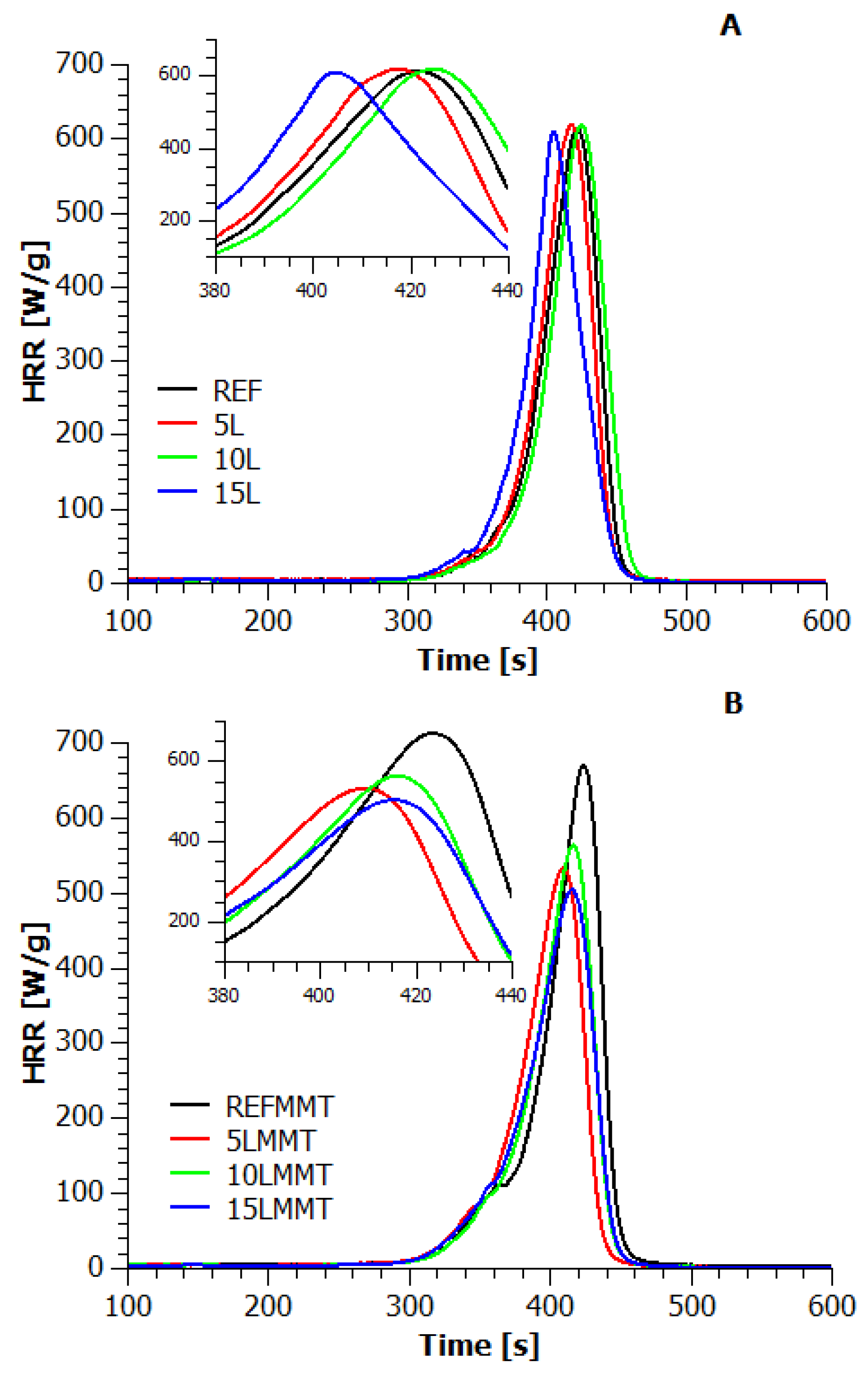
3.4. Microscale Combustion Calorimetry (MCC)

On the basis of the microcalorimetry test, it was possible to obtain information on the heat release rate (HRR) as a function of temperature and time.
The effect of introducing MMT in an amount of 3% by weight to the polyamide matrix was shown by the point of heat release rate (PHRR) value of 670.2 W/g. Of all the obtained results, this value was the highest. In addition, it was achieved at the same time and temperature as in the REF material. It may suggest that the introduction of nanofiller adversely affected the thermal effect of PA6 decomposition. However, the effect of achieving a higher peak on the HRR curve in relation to virgin polymer is often caused by the release of volatiles evolving through the decomposition of low-molecular-weight organic compounds used for the MMT modification, such as ammonium salts [35].
The HRR curves of coated materials using the LbL method are shown in Figure 4. The adsorption of triple layers on the surface of a pure polyamide matrix did not contribute to a visible change in the PHRR value, because even for 15L material it is about 0.65%. However, a significant change in the time and temperature values of reaching the maximum heat release rate was observed. With the increase in the number of deposited layers, the peaks shifted towards lower temperatures. The difference between the material temperature values REF and 15L was 16 °C (Table 5). In addition, the time to reach the maximum point of the HRR curve for this material was decreased by 18 s.
The application of the triple layers to the reinforced aluminosilicate matrix of polyamide 6 resulted in a visible reduction in the rate of heat release. The introduction of 15 triple layers onto the surface of the nanocomposite reduced the PHRR value by 18% compared to a non-modified matrix with no significant effect at the temperature at which the PHHR was achieved. The effect of reducing the PHRR of this material was even greater when it was compared with the REFMMT sample (the observed flame-retardant effect was as high as 25%).
The high temperature of the conducted study affected the total destruction of the protective barrier created. Whilst analyzing the course of all the pyrolysis and combustion microcalorimetry decomposition profiles, no changes in the shape of the peaks were observed. The application of 5–15 triple layers by LbL on a pristine PA6 matrix did not have a visible effect on reducing the maximum heat release rate. In the case of a reinforced polyamide matrix, this effect was much larger. The synergistic effect of MMT and the compounds constituting the triple-layer deposited on the polyamide 6 surface probably had an impact on reducing the maximum amount of heat released. During the combustion of the material, the embedded layers created a protective barrier preventing the thermal decomposition of the surfactant used for the organophilization of MMT. It can be assumed that during the thermal decomposition of the compound based on iodo-bis(triphenylphosphino)copper, phosphoric acid anhydride or its derivatives are produced, which in turn are the source of free radicals that can recombine with the radicals produced as a result of the degradation of PA6 [36]. In addition, iodine anions could inhibit the reactions occurring in the flame, and copper atoms prevent the formation of harmful phosphine [37]. Most probably, the applied disodium H-phosphonate layer and sodium MMT became a catalyst for carbonization, and the phosphorus compounds reacted with carbon, resulting in a reduction in PHHR. In addition, the deposition of sodium MMT together with iodo-bis(triphenylphosphino)copper could contribute to the dispersion of copper compounds and the formation of Cu–P–Si bonds during the thermal decomposition, as a result of which the produced coating was characterized by greater durability [15,38,39].
In order to get additional knowledge on the degradation course of the composite materials studied, the deconvolution of HRR = f (T) curves of REF, REFMMT, 15L, and 15LMMT was performed (Figure 5).
On the basis of the performed separation of signals, a four-stage mechanism of decomposition of samples without organofiller and the three-stage mechanism of decomposition of samples with organofiller could be postulated. For all of the presented materials, the rate of heat release during the first stage of degradation was visibly lower in relation to the second and third stages. For the REF and REFMMT materials, there were significantly smaller differences between the second and third signals compared to the 15L and 15LMMT samples. The application of triple layers to the surface of reinforced as well as unreinforced polyamide matrix could not have an influence on the change of the degradation mechanism. Differences presented in Figure 5C,D were probably caused by a lack of organophilized MMT in the PA6 matrix, which played the role of stabilizer in the range of 450–500 °C.
Based on the curves obtained as a result of the HRR test, the total heat release (THR) was calculated. The HRR results referred to the sample based solely on polyamide 6 (assuming its THR value was 100%) are shown in Figure 6.
The introduction of MMT as a filler resulted in a significant increase in the total amount of heat released. In comparison to the reference material, its energy emission rate increased by as much as 12.2%. The effect of depositing the triple layers on the surface of the nanocomposite was lowering the THR value. There was a 4.0% decrease in THR of the composition in a sequence of 15LMMT in combination with an unmodified polyamide matrix.
The analysis of the obtained results of the maximum speed and the total amount of heat released proved the effectiveness of the layer-by-layer method to obtain the effect of reduced flammability. The best results in relation to the reference sample were noted for the 15LMMT material. In the case of other materials, the PHRR and THRR values obtained through the use of pyrolysis and combustion microcalorimeter have shown a similar trend.

3.5. TG vs. MCC

We performed TG measurements at the same heating rates as in the MCC experiments, and the results of both experimental techniques are compared in Figure 7 and Figure 8. Based on the procedure proposed in work [40], for the TG and MCC data, the reaction rates were calculated from the Formulas (2)–(4), respectively:
r m ˙ = ( d m / d t ) / ( m 0 m )
r q ˙ = q ˙ / Δ q ¯
Δ q = q ˙ / r m ˙
where:
  • r m ˙ the reaction rate of weight loss, s−1;
  • d m / d t the weight derivative over time;
  • m 0 the initial mass of the sample, kg;
  • m the final mass of the sample, kg;
  • r q ˙ the reaction rate of heat release, s−1;
  • q ˙ the specific heat release rate, W/g;
  • Δ q the heat of combustion per unit mass of the sample, J/g;
  • Δ q ¯ the total heat of combustion per unit mass of the sample, J/g.
Such a comparison leads to the conclusion that most of the sample mass is lost during the main step, and also that most of the heat release occurs in the oxidation of volatiles produced in the same step. This indicates that the heats of combustion of the volatiles produced in the main step are very different for the samples with and without nanofiller. The heat of combustion evaluated by dividing the measured heat release rate by the measured mass loss rate is plotted in Figure 8 as a function of sample temperature.
It can be seen that the volatiles released up to 400 °C have a very low calorific value (~2.5 kJ/g for the samples without MMT, and ~3.7 kJ/g for the samples with MMT, approximately), while most combustible volatiles (with the heat of combustion in the range of 20–40 kJ/g) are produced at higher sample temperatures around 500–600 °C. It is worthy to note that the integral heat of combustion differs significantly from these values (~29.23 kJ/g for the samples without MMT and ~28.49 kJ/g for the samples with MMT, approximately). We noticed that, with increasing applied layers, the heat of combustion in the final stage of combustion is reduced to almost half, with 15 layer deposition in both types of samples, with or without MMT. However, the treated samples have a slightly better char forming ability, which was also observed in both the TG and MCC investigations.

3.6. Morphological Analysis

The SEM investigations of the 10L and 10LMMT samples (Figure 9) confirm that covering the surface of the PA6 and the PA6/MMT composites with ten triple layers did not contribute to the formation of a regular structure. The deposition of ten triple layers on the surface of the composites resulted in a highly porous structure. The obtained microscopic images show numerous fibers with uneven distribution on the surface of the tested material penetrating each other. It should be noted that the LbL method may cause the partial reorganization of crystalline and amorphous phases on the surface.
It may lead to the formation of local polycrystalline anisotropic structures, visible in Figure 9A,B, built of interpenetrating micro- and nanofibers. However, greater surface coverage was observed for the composites containing MMT. Such observations could confirm the impact of the presence and distribution of the mineral filler on the deposition of appropriate layers. The reason for this could be the local and temporary generation of weak, secondary binding forces between the nanofiller particles dispersed in the matrix and the particles of the compound present in the applied solution or in polyelectrolyte dispersion. Microscopic observations confirm the supposition that the surfaces on which the formation of (even local) interwoven fibrous crystal structures was observed showed a tendency to protect the entire material against the destructive effects of heat, contributing, among other things, to the reduction of the maximum point of heat release rate (PHRR).
The adsorption of the compounds constituting the solution and polyelectrolyte dispersions resulted in the unification of the Rt values (Table 6) of both the pure and montmorillonite-reinforced polyamide matrix. The value of this parameter for compositions 5L, 10L and 15L oscillated around 4.70 μm, while 5LMMT, 10LMMT, 15LMMT were about 3.60 μm. The deposition of the triple layers the by the LbL technique on pure polyamide 6 significantly reduced the Ra parameter, which suggested an improvement in the quality of the obtained surface. The material became smoother, indicating that the triple layers filled the pores on the surface of PA6.
In the case of the nanocomposite samples, the value of the parameter mentioned above did not significantly change concerning the reference material reinforced with montmorillonite. In addition, for these samples, the distances between the peak and the valley were the same as those determined for the reference materials.
The analysis of surface roughness proved that the use of the LBL method resulted in the even adsorption of the polyelectrolyte solution and dispersions (roughness profile curves—Figure 10 and Figure 11), contributing to a significant reduction in the plane unevenness in the case of the composite. The average value of the Ra parameter obtained by the REFMMT, 5LMMT, 10LMMT, 15LMMT materials was about 0.23 μm. According to the literature, it is the value that characterizes the surfaces after grinding and then polishing [41].
Thanks to the 3D mapping of the 15L (Figure 10) and 15LMMT (Figure 11) sample surfaces, it was possible to determine the height of the triple layers applied. The blank film REF (PA6) had a thickness of 28 μm. The application of the five layers 5L increased the material thickness to about 63 μm. The application of another five layers to obtain 10L increased the thickness of the material to about 105 μm. The treatment of the sample with subsequent layers to obtain 15L increased the thickness of the sample profile to over 145 μm (max 147.17 μm). This means that, on average, one triple layer had a thickness close to 40 μm.
However, the REFMMT film (PA6/MMT) had a thickness of 55 μm. The application of the 5LMMT triple layers increased the thickness to about 112 μm. The deposition of another five layers to obtain 10LMMT increased the thickness of the material to about 187 μm. The last treatment cycle to obtain 15LMMT increased the thickness of the composite sample to over 260 μm (max 262.17 μm). The calculated average value of one triple layer’s thickness was close to 69 μm.
The most important thing is that in both cases, the smallest thickness value was obtained by the first triple layer, and the next two had a similar value (35/42/42 for REF and 57/75/75 for REFMMT). This means that the composite surface containing a quaternary anion salt capable of producing short-range interactions between the applied compound and the surface of the material, has a much higher affinity for layer deposition. This would explain the behavior of the sample during the combustion, primarily at high temperatures of 400–550 °C. Since the new impacts were created, although they do not significantly affect the rate of reaction of sample decomposition, they certainly change its visible mechanism, e.g., by reducing the PHRR value or the heat of combustion just in the final phase of decomposition.

4. Conclusions

The application of multilayered protective coatings by using the LbL technique on PA6 is a promising way to reduce the flammability of this important engineering polymer. In the course of our systematic study, it has been found that the LOI test did not show a significant effect of reducing the flammability of the 15LMMT material. The UL-94 test, both in the vertical (VB) and horizontal (HB) test, made it possible to isolate the polyamide compositions coated with triple layers in the amount of 5–15, as the materials of the best combustibility class compared to the others. In horizontal mode, these composites were not completely burned, and the triple layers deposited on their surface affected the lack of ignition of cotton.
Further information on the flame-retarding effect was obtained as a result of the microcalorimetric analysis. For the polyamide matrix and PA6/MMT nanocomposites, a tendency to reduce the heat release rate (HRR) with an increasing degree of coverage of the polymer matrix was found. The deposition of 15 triple layers on the surface of the nanocomposite using the LbL method, resulted in a 20% reduction in the maximum point of HRR. This improvement in fire resistance was most likely due to the synergistic effect caused by the introduction of aluminosilicate into the polyamide matrix and the simultaneous application of H-phosphonate, montmorillonite and a copper complex, whose action was based on the formation of a protective barrier during the combustion of the composite. Interestingly, the effect of reducing the PHRR of this material was even greater when it was compared with the REFMMT sample—the observed flame-retardant effect was as high as 75%.
Based on the discussion of the results, it was found that the layer-by-layer method could be successfully used to considerably improve the flammability characteristics of the polyamide 6-based hybrid composites, under specific conditions.

Author Contributions

Conceptualization, T.M.M. and M.W.; methodology, T.M.M. and K.P.; software, T.M.M. and K.K.; validation, T.M.M., K.K. and K.P.; formal analysis, T.M.M. and A.M.; investigation, T.M.M., A.M. and M.W.; resources, K.P.; data curation, P.R.; writing—original draft preparation, T.M.M. and P.R.; writing—review and editing, T.M.M., P.R. and M.W.; visualization, K.K.; supervision, K.P.; project administration, T.M.M.; All authors have read and agreed to the published version of the manuscript.

Funding

This research received no external funding.

Conflicts of Interest

The authors declare no conflict of interest.

References

  1. Liu, K.; Li, Y.; Tao, L.; Xiao, R. Preparation and characterization of polyamide 6 fibre based on a phosphorus-containing flame retardant. RSC Adv. 2018, 8, 9261–9271. [Google Scholar] [CrossRef] [Green Version]
  2. Majka, T.M.; Leszczyńska, A.; Kandola, B.K.; Pornwannachai, W.; Pielichowski, K. Modification of organo-montmorillonite with disodium H-phosphonate to develop flame retarded polyamide 6 nanocomposites. Appl. Clay Sci. 2017, 139, 28–39. [Google Scholar] [CrossRef]
  3. He, W.-T.; Liao, S.-T.; Xiang, Y.-S.; Long, L.-J.; Qin, S.-H.; Yu, J. Structure and Properties Study of PA6 Nanocomposites Flame Retarded by Aluminium Salt of Diisobutylphosphinic Acid and Different Organic Montmorillonites. Polymers 2018, 10, 312. [Google Scholar] [CrossRef] [Green Version]
  4. Horrocks, R.; Sitpalan, A.; Zhou, C.; Kandola, B.K. Flame retardant polyamide fibres: The challenge of minimising flame retardant additive contents with added nanoclays. Polymers 2016, 8, 288. [Google Scholar] [CrossRef] [PubMed] [Green Version]
  5. He, W.; Zhu, H.; Xiang, Y.; Long, L.; Qin, S.; Yu, J. Enhancement of flame retardancy and mechanical properties of polyamide 6 by incorporating an aluminum salt of diisobutylphosphinic combined with organoclay. Polym. Degrad. Stab. 2017, 144, 442–453. [Google Scholar] [CrossRef]
  6. Liu, T.; Wang, R.; Dong, Z.-F.; Zhu, Z.-G.; Zhang, X.-Q.; Liu, J.-G. Role of caged bicyclic pentaerythritol phosphate alcohol in flame retardancy of PA6 and mechanism study. J. Appl. Polym. Sci. 2018, 135, 46236. [Google Scholar] [CrossRef]
  7. Zhong, Y.; Zhang, L.; Fischer, A.; Wang, L.; Drummer, D.; Wu, W. The effect of hBN on the flame retardancy and thermal stability of P-N flame retardant PA6. J. Macromol. Sci. Part A 2018, 55, 17–23. [Google Scholar] [CrossRef]
  8. Yuan, L.; Feng, S.; Hu, Y.; Fan, Y. Effect of char sulfonic acid and ammonium polyphosphate on flame retardancy and thermal properties of epoxy resin and polyamide composites. J. Fire Sci. 2017, 35, 521–534. [Google Scholar] [CrossRef]
  9. Wendels, S.; Chavez, T.; Bonnet, M.; Salmeia, K.A.; Gaan, S. Recent Developments in Organophosphorus Flame Retardants Containing P-C Bond and Their Applications. Materials 2017, 10, 784. [Google Scholar] [CrossRef] [Green Version]
  10. Holdsworth, A.F.; Horrocks, A.R.; Kandola, B.K.; Price, D. The potential of metal oxalates as novel flame retardants and synergists for engineering polymers. Polym. Degrad. Stab. 2014, 110, 290–297. [Google Scholar] [CrossRef]
  11. Li, M.; Cui, H.; Li, Q.; Zhang, Q. Thermally conductive and flame—Retardant polyamide 6 composites. J. Reinf. Plast. Compos. 2016, 35, 435–444. [Google Scholar] [CrossRef]
  12. Zope, I.S.; Dasari, A.; Guan, F.; Yu, Z.Z. Influence of metal ions on thermo-oxidative stability and combustion response of polyamide 6/clay nanocomposites. Polymer 2016, 92, 102–113. [Google Scholar] [CrossRef]
  13. Zhan, Z.; Xu, M.; Li, B. Synergistic effects of sepiolite on the flame retardant properties and thermal degradation behaviors of polyamide 66/aluminum diethylphosphinate composites. Polym. Degrad. Stab. 2015, 117, 66–74. [Google Scholar] [CrossRef]
  14. Iler, R.K. Multilayers of colloidal particles. J. Colloid Interface Sci. 1966, 21, 569–594. [Google Scholar] [CrossRef]
  15. Kadir, A.; Abdelghani, L.; Vincent, B.; Maude, J.; Serge, B.; Valérie, T.; David, R. Polyallylamine-montmorillonite as super flame retardant coating assemblies by layer-by layer deposition on polyamide. Polym. Degrad. Stab. 2013, 98, 627–634. [Google Scholar]
  16. Qiu, X.; Li, Z.; Li, X.; Zhang, Z. Flame retardant coatings prepared using layer by layer assembly: A review. Chem. Eng. J. 2018, 334, 108–122. [Google Scholar] [CrossRef]
  17. Malucelli, G. Surface-Engineered Fire Protective Coatings for Fabrics through Sol-Gel and Layer-by-Layer Methods: An Overview. Coatings 2016, 6, 33. [Google Scholar] [CrossRef] [Green Version]
  18. Apaydin, K.; Laachachi, A.; Ball, V.; Jimenez, M.; Bourbigot, S.; Toniazzo, V.; Ruch, D. Intumescent coating of (polyallylamine-polyphosphates) deposited on polyamide fabrics via layer-by-layer technique. Polym. Degrad. Stab. 2014, 106, 158–164. [Google Scholar] [CrossRef]
  19. Apaydin, K.; Laachachi, A.; Ball, V.; Jimenez, M.; Bourbigot, S.; Ruch, D. Layer-by-layer deposition of a TiO2-filled intumescent coating and its effect on the flame retardancy of polyamide and polyester fabrics. Colloids Surf. A Pchysicochem. Eng. Asp. 2015, 469, 1–10. [Google Scholar] [CrossRef]
  20. Mosurkal, R.; Muller, W.S. Layer-By-Layer Assembly of Halogen-Free Polymeric Materials on Nylon/Cotton. Fire Mater. 2014, 40, 206–2018. [Google Scholar]
  21. Kundu, C.; Wang, W.; Zhou, S.; Wang, X.; Sheng, H.; Pan, Y.; Song, L.; Hu, Y. A green approach to constructing multilayered nanocoating for flame retardant treatment of polyamide 66 fabric from chitosan and sodium alginate. Carbohydr. Polym. 2017, 166, 131–138. [Google Scholar] [CrossRef] [PubMed]
  22. Kundu, C.K.; Wang, X.; Song, L.; Hu, Y. Borate cross-linked layer-by-layer assembly of green polyelectrolytes on polyamide 66 fabrics for flame-retardant treatment. Prog. Org. Coat. 2018, 121, 173–181. [Google Scholar] [CrossRef]
  23. Majka, T.M.; Cokot, M.; Pielichowski, K. Studies on the thermal properties and flammability of polyamide 6 nanocomposites surface-modified via layer-by-layer deposition of chitosan and montmorillonite. J. Anal. Calorim. 2018, 131, 405–416. [Google Scholar] [CrossRef] [Green Version]
  24. Abbaszadeh, M.; Krizak, D.; Kundu, S. Layer-by-layer assembly of graphene oxide nanoplatelets embedded desalination membranes with improved chlorine resistance. Desalination 2019, 470, 114116. [Google Scholar] [CrossRef]
  25. Rahman, M.Z.; Kundu, C.K.; Nabipour, H.; Wang, X.; Song, L.; Hu, Y. Hybrid coatings for durable flame retardant and hydrophilic treatment of Polyamide 6.6 fabrics. Prog. Org. Coat. 2020, 144, 105640. [Google Scholar] [CrossRef]
  26. Kundu, C.K.; Wang, X.; Song, L.; Hu, Y. Chitosan-based flame retardant coatings for polyamide 66 textiles: One-pot deposition versus layer-by-layer assembly. Int. J. Biol. Macromol. 2020, 143, 1–10. [Google Scholar] [CrossRef]
  27. Kundu, C.K.; Wang, X.; Liu, L.X.; Song, L.; Hu, Y. Few layer deposition and sol-gel finishing of organic-inorganic compounds for improved flame retardant and hydrophilic properties of polyamide 66 textiles: A hybrid approach. Prog. Org. Coat. 2019, 129, 318–326. [Google Scholar] [CrossRef]
  28. Apaydin, K.; Laachachi, A.; Fouquet, T.; Jimenez, M.; Bourbigot, S.; Ruch, D. Mechanistic investigation of a flame retardant coating made by layer-by-layer assembly. RSC Adv. 2014, 4, 43326–43334. [Google Scholar] [CrossRef]
  29. Xiao, L.; Xu, L.; Yang, Y.; Zhang, S.; Huang, Y.; Bielawski, C.W.; Geng, J. Core-Shell Structured Polyamide 66 Nanofibers with Enhanced Flame Retardancy. ACS Omega 2017, 2, 2665–2671. [Google Scholar] [CrossRef] [Green Version]
  30. Wu, H.; Krifa, M.; Koo, J.H. Flame retardant polyamide 6/nanoclay/intumescent nanocomposite fibers through electrospinning. Text. Res. J. 2014, 84, 1106–1118. [Google Scholar] [CrossRef]
  31. Katsoulis, C.; Kandare, E.; Kandola, B.K. The effect of nanoparticles on structural morphology, thermal and flammability properties of two epoxy resins with different functionalities. Polym. Degrad. Stab. 2011, 96, 529–540. [Google Scholar] [CrossRef]
  32. Castrovinci, A.; Camino, G. Fire-Retardant Mechanisms in Polymer Nano-Composite Materials. In Multifunctional Barriers for Flexible Structure: Textile, Leather and Paper, 1st ed.; Camino, G., Duquesne, S., Magniez, C., Eds.; Springer: Berlin/Heidelberg, Germany, 2007; Volume 97, pp. 87–108. [Google Scholar]
  33. Zhang, W.; He, X.; Song, R.; Jiao, Q.; Yang, R. The influence of the phosphorus-based flame retardant on the flame retardancy of the epoxy resins. Polym. Degrad. Stab. 2014, 109, 209–217. [Google Scholar] [CrossRef]
  34. Technical Committee: ISO/TC 61/SC 4 Burning Behavior, ISO 1210: 1992 Plastics—Determination of the Burning Behaviour of Horizontal and Vertical Specimens in Contact with a Small-Flame Ignition Source, ICS: 13.220.40 Lgnitability and Burning Behaviour of Materials and Products 83.080.01 Plastics in General. Available online: www.iso.org (accessed on 11 February 2018).
  35. Singla, P.; Mehta, R.; Upadhyay, S.N. Clay Modification by the Use of Organic Cations. Green Sustain. Chem. 2012, 2, 21–25. [Google Scholar] [CrossRef] [Green Version]
  36. Salmeia, K.A.; Gaan, S.; Malucelli, G. Recent Advances for Flame Retardancy of Textiles Based on Phosphorus Chemistry. Polymers 2016, 8, 319. [Google Scholar] [CrossRef] [PubMed] [Green Version]
  37. Roth, M.; König, A.; Deglmann, P.; Uske, K.; Minges, C. BASF SE, Flame-Retardant Polyamides with Pale Color. U.S. Patent 20140080949A1, 20 March 2014. [Google Scholar]
  38. Faraji, S.; Rahim, A.A.; Mohamed, N.; Sipaut, C.S. A study of electroless copper-phosphorus coatings with the addition of silicon carbide (SiC) and graphite (Cg) particles. Surf. Coat. Technol. 2011, 206, 1259–1268. [Google Scholar] [CrossRef]
  39. Yi, D.; Yang, H.; Zhao, M.; Huang, L.; Camino, G.; Frache, A.; Yanga, R. A novel, low surface charge density, anionically modified montmorillonite for polymer nanocomposites. RSC. Adv. 2017, 7, 5980–5988. [Google Scholar] [CrossRef] [Green Version]
  40. Berkowicz, D.; Majka, T.M.; Żukowski, W. The pyrolysis and combustion of polyoxymethylene in a fluidised bed with the possibility of incorporating CO2. Energy Convers. Manag. 2020, 214, 112888. [Google Scholar] [CrossRef]
  41. Whitehouse, D. Surface and their measurements. In Kogan Page Science Paper Edition; Butterworth-Heinemann: London, UK, 2006. [Google Scholar]
Figure 1. The procedure of the triple-layer cycle of the layer-by-layer deposition on the polyamide 6 (PA6) or PA6/ montmorillonite (MMT) surface, including: deionized water (DI) washing and drying at 80 °C; dipping in MMT-Na+ dispersion; DI washing and drying at 80 °C; dipping in H-phosphonate (HP) solution; DI washing and drying at 80 °C; and dipping in iodo-bis(triphenylphosphino)copper (CC) solution.
Applsci 10 05007 g001
Figure 2. Thermograms of the materials with 5, 10, and 15 triple layers, deposited on the surface of (A) the PA6 and (B) the PA6/MMT nanocomposites.
Applsci 10 05007 g002
Figure 3. Overall thermal stabilization effect of the triple layers on polyamide 6.
Applsci 10 05007 g003
Figure 4. Heat release rate (HRR) as a function of time of the polymeric materials coated using the LbL method: (A) the samples without nanofiller; and (B) the samples with nanofiller.
Applsci 10 05007 g004
Figure 5. HRR = f (T) profiles and the deconvoluted curves from the primary data obtained using microcalorimetry for: (A) REF; (B) REFMMT; (C) 15L; and (D) 15LMMT.
Applsci 10 05007 g005
Figure 6. The total amount of heat released (THR) emitted by PA6 coated using the LbL method, compared with the REF material.
Applsci 10 05007 g006
Figure 7. Comparison of the thermogravimetry (TG) and microscale combustion calorimetry (MCC) measurements by determining the reaction rates detected by TG and MCC as a function of temperature during the thermal decomposition of the PA6 samples (heating rate 1 °C/min): (A) the samples without nanofiller; and (B) the samples with nanofiller.
Applsci 10 05007 g007
Figure 8. Comparison of the TG and MCC measurements by determining the heat of combustion as a function of temperature during the thermal decomposition of the PA6 samples (heating rate 1 °C/min): (A) the samples without nanofiller; and (B) the samples with nanofiller.
Applsci 10 05007 g008
Figure 9. SEM investigations of (A) the 15L and (B) the 15LMMT samples with the magnification of 350×.
Applsci 10 05007 g009
Figure 10. Two-dimensional roughness profile (left) and the 3D surface structure (right) for the sample 15L.
Applsci 10 05007 g010
Figure 11. Two-dimensional roughness profile (left) and the 3D surface structure (right) for the sample 15LMMT.
Applsci 10 05007 g011
Table 1. Temperatures at which 5%, 10%, 20%, and 50% mass loss occurs for the PA6 and the PA6/MMT nanocomposites stabilized with triple layers.
SampleT5% (°C)T10% (°C)T20% (°C)T50% (°C)Tmax (°C)Residue at 600 °C (%)
REF3743914124404450.9
5L3833994174424542.4
10L3813994184424491.8
15L3773954124394501.5
REFMMT3363844094384451.8
5LMMT3793954184444542.0
10LMMT3733974184444602.6
15LMMT3724034214454532.5
Table 2. Limiting oxygen index (LOI) value summary for the coated polymeric materials using the layer-by-layer (LbL) method.
SampleLOI (% Oxygen)∆LOI (% Oxygen)
REF19.8-
5L19.6−0.2
10L19.4−0.4
15L19.3−0.5
REFMMT19.7-
5LMMT19.90.2
10LMMT19.90.2
15LMMT20.10.4
Table 3. Results of the UL-94 combustion carried out in a horizontal position (HB) for the composites covered by using the LbL method.
SampleBurning Time (s)Length of the Burnt Sample (mm)Burning Rate (mm/min)Number of DropsType of Standard Class
REF441 ± 210014 ± 1280I
5L-Did not reach the starting line *--II
10L264 ± 26014 ± 1151III
15L271 ± 210022 ± 1179I
REFMMT430 ± 210013 ± 166IV
5LMMT255 ± 210024 ± 119V
10LMMT266 ± 210023 ± 111V
15LMMT275 ± 210022 ± 126V
* the flame did not exceed the 25 mm line (measuring start line) at which the measuring section began
Table 4. Results of the UL-94 combustion carried out in a vertical position (VB) for the composites covered by using the LbL method.
SampleBurning Time (s)Length of the Burnt Sample (mm)Burning Rate (mm/min)Number of DropsType of Standard Class
REF40274122FV-2
5L24212531121-
10L47314032FV-0
15L58444645FV-1
REFMMT1481255013-
5LMMT861258712-
10LMMT80125944-
15LMMT661251144-
Table 5. Point of heat release rate (PHRR) parameters for the materials coated utilizing the LbL method.
SamplePHRR (W/g)Temperature to Reach PHRR (°C)Time to Reach PHRR (s)
REF613.6473422
5L619.4468417
10L618.8472424
15L609.6457404
REFMMT670.2471423
5LMMT533.3469409
10LMMT564.2470416
15LMMT504.4468415
Table 6. Roughness parameters for the materials coated utilizing the LbL method, where: Ra—the arithmetical mean roughness; Rmax—the maximum peak height; Rt—the linear distance between the top of peak and base of the valley; and Rz—the height of roughness presented on a scale of ten points.
SampleRt (μm)Rmax (μm)Rz (μm)Ra (μm)
REF5.04 ± 1.594.54 ± 1.083.21 ± 0.540.58 ± 0.23
5L4.54 ± 1.904.15 ± 1.952.67 ± 0.860.36 ± 0.18
10L4.69 ± 1.504.60 ± 1.462.34 ± 0.500.28 ± 0.09
15L4.79 ± 1.594.38 ± 1.022.20 ± 0.830.31 ± 0.37
REFMMT3.35 ± 0.663.15 ± 0.832.05 ± 0.060.23 ± 0.02
5LMMT3.95 ± 0.553.93 ± 2.262.25 ± 0.550.23 ± 0.06
10LMMT3.64 ± 0.583.56 ± 0.472.43 ± 0.040.25 ± 0.01
15LMMT3.56 ± 0.593.56 ± 0.592.99 ± 0.450.24 ± 0.18

