Abstract
Overhead distribution lines can be seriously damaged from lightning events because both direct and indirect events can cause flashovers along the line. The lightning performance of such power lines is usually computed neglecting the effect of corona discharge along the conductors: in particular, the corona discharge determined by the indirect lightning event is taken into account only by few researchers because it can have meaningful impacts only in few cases. However, when we deal with overhead distribution lines with high Critical Flashover value (CFO) and small diameters, the corona discharge caused by indirect events has to be taken into account. This paper shows the effects of corona discharge in the lightning performance computation of overhead distribution lines. The analysis will involve different configurations in terms of line diameter and air conditions, focusing on the negative effect of corona discharge in the number of dangerous events that determine line flashovers.
1. Introduction
Lightning is one of the most important issues in terms of protection of transmission and distribution lines [1]. Their protection requires an accurate evaluation of the insulation coordination system [2] as well as a correct computation of the number of dangerous events striking the line per year. The latter parameter is usually computed through the lightning performance procedure—a high number of lightning events, each of them characterized by different parameters extracted from their own Probability Density Function (PDF), is generated and their effects on the power system are computed through a simplified method [1,3,4] or through a numerical code [5,6,7,8,9]. The number of events that exceeds a threshold value depending on the line Critical Flashover value (CFO) is considered dangerous. Each event can be classified as a direct or indirect stroke in accordance to the electrogeometrical criterion [10]. When we deal with transmission lines, characterized by high CFO, the majority of the dangerous events is represented by direct strokes, while dealing with overhead distribution lines, indirect strokes are the most affecting category.
The lightning performance procedure of overhead distribution lines has been deeply studied and optimized by several researchers and usually requires the use of a numerical code. Among them, Reference [7] proposes a procedure based on LIOV code which takes into account a triangular waveform for the channel-base current and the possibility to consider complex power systems as well as a finite ground conductivity. The authors of Reference [11] provide an application of the recursive stratified sampling technique in order to reduce the computational effort. In Reference [6], the authors propose a procedure which can be extended to whatever channel-base current based on the construction of an electromagnetic field database.
The corona effect, that is, the process that describes an electrical discharge by the ionization of the fluid that surrounds a conductor, usually, is not considered in the lightning performance of distribution lines (i.e., taking into account both direct and indirect events): typically due to its occurrence only for small conductor diameters and in case of direct events, which represents the less significant part. However, as pointed out in this work, there are some cases where the corona discharge occurs also for indirect events, leading to a meaningful impact in the lightning performance evaluation.
When one deals with direct events, the corona discharge affects the surge propagation more than the ground resistivity but reduces the voltages induced on the line [12]. On the other side, when one deals with indirect strokes, Reference [12], “computation results showed a significant increase in the amplitude of the induced voltages in presence of corona”. The result has been confirmed by Reference [13]. The implementation of corona discharge in the computation of lightning-induced voltages has been based on two different strategies: (i) The concept of dynamic capacitance has been proposed in Reference [12] that is, when the induced voltage overcomes a threshold, the corona discharge determines an increase of the per unit length capacitance involved in the Agrawal model [14]; consequently, the dynamic capacitance mimics the experimental q-v characteristic of the corona discharge [15]. (ii) In References [16,17] the 3D–FDTD code simulates the corona discharge giving different values to the conductivity of the cell where corona effect is located; the main difference with the previous approach is that here the q-v characteristic results as an output calculation from the numerical integrations, while in the previous one appears as an input of the problem.
However, both approaches lead to the same conclusions, that is, the enhancement of the induced voltage. Unfortunately, to the best of author’s knowledge, both approaches limit their studies to the evaluation of the effect of a single event striking in the proximity of the line and a parametric analysis aimed at relating the most affecting parameters (line diameter, environmental conditions) to the induced voltage is missing.
The aim of this work is to evaluate the effects of corona discharge in the lightning performance computation of an overhead distribution line and to make some sensitivity analysis on the parameters that mainly affect the enhancement of the number of dangerous events striking the line. The implementation of corona discharge will be based on the procedure described in Reference [5] and validated in Reference [18,19].
The paper is structured as follows: Section 2 recalls the concepts of the corona discharge, Section 3 describes the implementation of corona discharge in the procedure developed in Reference [5] and Section 4 focuses on the lightning performance computation. Later, the sensitivity analysis on the main parameters (line diameter and environmental conditions) affecting the enhancement of dangerous events due to corona is proposed in Section 5. Finally, in Section 6, some conclusions are drawn.
2. The Corona Effect
According to Reference [20], the corona discharge can occur when the electric field in air in the vicinity of object at high voltages or exposed to high electric fields may overhelm the critical electric field able to create electron avalanches in air. The corona discharge can be either a positive of negative discharge and, according to Reference [21], the corona occurs on a conductor when the electric field on its surface is higher than the critical field E.
where m is a surface state coefficient quantifying the irregularities of the cable and generally deduced from tests. This formula has been developed assuming 20 C, a pressure of 760 mmHg and a humidity of the air equal to 11 g/m. Please note that r is the radius of the conductor and is expressed in cm. It is important to notice that according to Reference [21] the variation of humidity changes the critical field E. With respect to (1) an increase of the air humidity to 18 g/m leads to an increase of the critical electric field of 2%. Figure 4 of Reference [21] showed the variation of the critical electric field as a function of the air humidity.
In Reference [22], recently, the authors provided a new expression for the critical electric field under variable atmospheric conditions, which is here proposed for sake of completeness.
where
being the relative air density, H the air humidity, a coefficient depending on the number of strands in the outer layer of the conductor and coefficients depending on the voltage polarity (Table 1 of Reference [22]).
In addition to this, the corona discharge occurs if a free electron is available at the instant when the electric field overcomes the critical value in (1). It means that there is a certain time lag between the application of the electric field and the time of creation of a free electron in the gas volume [20]: this time is known as the statistical time lag or inception time delay. The statistical time lag decreases when the applied electric field increases.
Once a free electron is found, the corona discharge occurs, but its sustainment is achieved only if the electric field in front of the streamers is not lower than 4 to 5 kV/cm (positive streamers) and 11 to 18 kV/cm (negative streamers) [20].
From a macroscopic point of view, the corona discharge on the surface of a conductor can be viewed as an increase of the capacitance of the conductor, while the inductance remains constant due to the low conductivity of the corona region. The capacitance can be estimated from the q-v curve, which can be obtained by experimental tests or by models in literature. An example is proposed in Figure 9 of Reference [12].
The lower line of Figure 9 of [12] represents the q-v curve measured during the increase of the voltage (i.e., when ), while the upper line represents the q-v curve measured during the decrease of the applied voltage. In this second phase, the slope, that is, the capacitance, is constant and equal to the geometrical capacitance of the line because it is well-known that corona discharge occurs only when the applied voltage derivative is positive. The lower line presents an increase of the slope with applied voltages higher than 130 kV, which denotes the occurrence of the corona discharge
3. Implementation of Corona Discharge
This section shows the implementation of the corona effect in the procedure proposed in Reference [5] following the one in Reference [12].
The main idea of this approach is to consider a dynamic capacitance in the Agrawal model. As in Reference [12], the dynamic capacitance has been described through the following equation, which aims at reproducing the experimental q-v characteristics.
where is related to the sudden change of the capacitance when the voltage exceeds the corona threshold and is related to the gradual increase of the capacitance when the voltage is rising above the threshold. is the geometrical capacitance of the line and is the voltage on a generic conductor at time instant t and at a distance x from the beginning of the line. The voltage threshold is related to , to the conductor radius r and to the critical electric field in (1), according to
Here, as usual, is the electric permittivity in vacuum.
4. Corona Effect Influence on the Lightning Performance
This section shows the enhancement of the number of dangerous lightning events due to the corona effect.
Let us consider a single-phase overhead distribution line whose details are available in Table 1. In order to avoid reflections, the line extremities are matched. Moreover, let us suppose a ground conductivity of 1 mS/m and a ground permittivity of 10.

Table 1.
Line details.
According to Reference [6] and supposing a lightning channel height of 8 km and a propagation velocity along the lightning channel of (being the light speed in vacuum ), the lightning performance of the overhead distribution line is computed as follows (for further details check Figure 1):
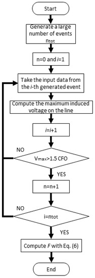
Figure 1.
Flowchart of the lightning performance computation.
- A counter n is initialized to 0.
- A large number of events, able to guarantee the convergence of the Monte-Carlo procedure (here 10,000), is generated. Each one is characterized by a stroke location extracted from a uniform distribution, peak current and front duration extracted from the log-normal distributions proposed in Reference [1]. Please note that the channel-base current is assumed to be the typical Heidler’s first stroke waveform with variable front duration [23].
- Each event is classified as direct or indirect one according to the EGM criterion [24]. In any case the maximum induced voltage on the line is computed through the procedure in Reference [5].
- For each event, the maximum voltage is compared with the line CFO. If it is greater than 1.5 CFO [1], the counter n is increased by one.
- Once all the considered events have been evaluated, the total number of dangerous events n is obtained and the number of flashovers per year per 100 km of line is computed according to References [1,7]where is the ground flash density expressed as number of flashes per square kilometer per year ad is the maximum value of the y-coordinate where the events are extracted. According to Reference [1], is a function of the CFO and it is computed through the extended Rusck’s formula [25], choosing as lightning current the maximum value () obtainable from the probabilistic density function.where is the ground conductivity.
For what concerns the corona effect, in the following we assume , and [12]. Consequently, kV/cm and kV.
Figure 2 shows the number of dangerous events per 100 km of line per year with the corona effect (solid black line) and without (red dashed line). As can be easily seen, when we deal with overhead distribution lines characterizred by very low CFO (≤100 kV), the corona discharge does not increase the number of flashovers. On the other side, when the CFO is higher, the influence of corona effect is meaningful. This result is in agreement with the conclusions of References [12,17], which have highlighted an increase of the lightning-induced voltages due to the corona effect. In particular, the enhancement can be caused by the decrease of the wave propagation velocity due to the increase of the line capacitance.
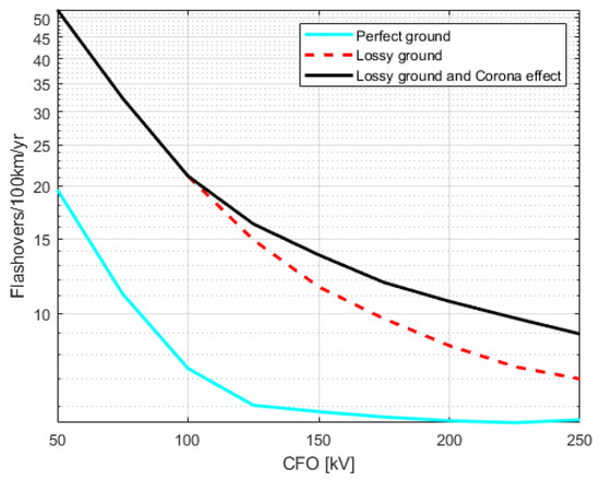
Figure 2.
Number of dangerous events on an overhead distribution line. Comparison between perfect ground, lossy ground and lossy ground with corona discharge.
In order to quantify the importance of the corona effect, again in Figure 2 the lightning performance without introducing corona effect and considering a perfect conducting ground (cyano solid line) has been proposed. The percentage enhancement of the number of flashovers due to corona is comparable with the one caused by considering a lossy ground (Table 2) especially when the CFO is high—when the CFO overcomes 250 kV the dominant effect is ascribed to the corona discharge.

Table 2.
Percentage enhancement—the second column describes how the lossy ground enhances the number of flashovers with respect to the PEC ground, while the third column describes how the corona effect enhances the number of flashovers with respect to the lossy ground case.
5. Sensitivity Analysis
This section aims at evaluating the flashovers variation due to corona discharge as a function of conductor surface state conditions, diameter and air humidity.
5.1. Surface Conditions
The effect of the surface conditions is taken into account by varying the surface state coefficient m. A minimum value of and a maximum value of are here considered [26]. Figure 3 shows the number of dangerous events per 100 km per year, computed for six different values for m in the selected range. For sake of completeness, the case treated in Figure 2 is here reported as the black line. The corresponding values of critical electric field and voltage can be found easily from Equations (1) and (5).
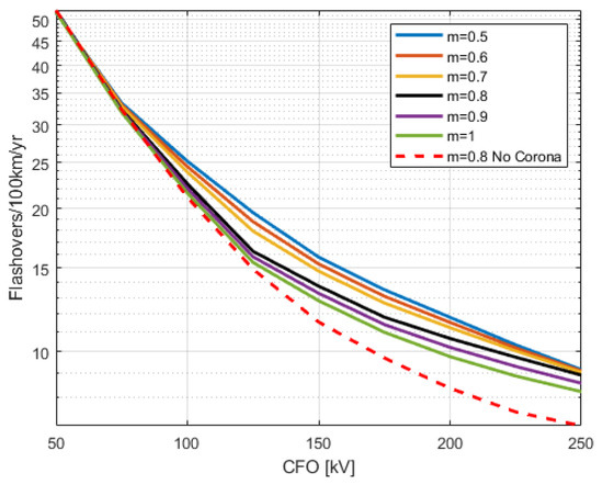
Figure 3.
Comparison of the lightning performance of an overhead distribution line with different surface state conditions—the red dot line represents the case when the corona effect is not considered.
The number of dangerous events increase with the decrease of the surface coefficient since it corresponds to a linear decrease of the critical electric field.
Figure 4 shows the percentage variation (with respect to ) of the number of flashovers as a function of the surface state coefficient for different line CFO.
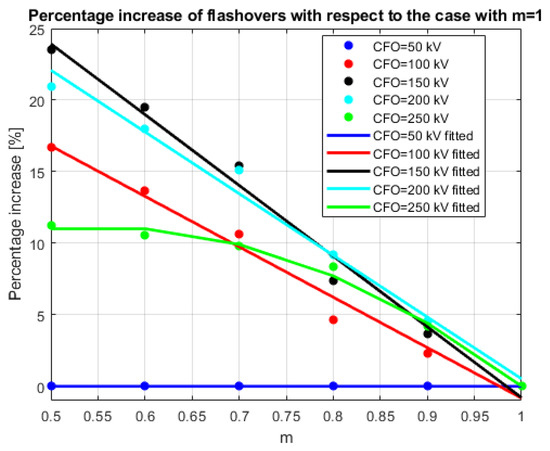
Figure 4.
Percentage variation of the number of flashovers as a function of the surface state coefficient.
Figure 4 shows that the percentage increase is negligible for kV: this is obvious as the corona effect contributes to the enhancement of the lightning-induced voltages only when the travelling wave overcomes , which is usually really higher than 50 kV. As a consequence, when kV, those cases are already defined as dangerous whatever is the value of m. On the other hand, when kV the curve can be well-described by a second-order polynomial because there is a sort of saturation for low values of m. This can be related to the fact that low values of m correspond to a decrease of . In other words, the corona discharge contributes to the enhancement of the lightning-induced voltages also when the voltage on the line is low. However, the increase due to corona is not sufficient to overcome the threshold set with kV, thus its effect on the enhancement of the flashovers number is less evident. Finally, the behaviour of the percentage increase for CFO kV is substantially linear, as shown by the fitting provided in Figure 4. This is in agreement with the linear variation of the critical electric field with respect to m. A decrease of the surface coefficient determines a linear decrease of ; the low value of causes an higher occurrence of the corona discharge, causing an enhancement of the lightning-induced voltages and of the line flashovers. The higher increases can be noticed for and 200 kV.
Equation (8) provides the general expression used for finding the fitting curve, that express the percentage increase as a function of m
The values of the parameters , amd are reported in Table 3, where also the index is shown, for quantify the reliability of the fitting.

Table 3.
Fitting coefficients and index.
5.2. Conductor Diameter
The effect of the conductor diameter is analysed, taking into account different values typical of overhead distribution lines (from 5 mm to 60 mm). The other line parameters have been described in the previous sections and in this framework we consider . Figure 5 shows that the influence of the corona discharge is negligible when the diameter is greater than 30 mm. Moreover, for very thin conductors ( mm), the corona discharge increases the number of flashovers even if the line CFO is very low (<100 kV): this can be ascribed to the low value of the critical electric field associated to such diameter.
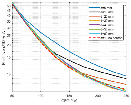
Figure 5.
Comparison of the lightning performance of an overhead distribution line with different diameters—the red dot line represents the case when the corona effect is not considered.
Figure 6 analyses the percentage variation (with respect to the case with mm) of the number of flashovers as a function of the conductor diameter for different line CFO.
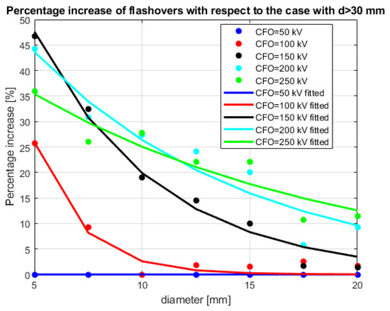
Figure 6.
Percentage variation of the number of flashovers as a function of the conductor diameter.
Figure 6 confirms that, if the line CFO is 50 kV, the enhancement is negligible for the same reason presented in the previous subsection. Considering a line CFO of 100 kV and 150 kV corresponds to a consistent enhancement of the percentage for low values of the diameter (<10 mm) and a flatness of the increase if the diameter is greater than 10 mm. As a consequence the two curves can be well described by an exponential. This behaviour is related to the high values of when we consider a diameter larger than 10 mm: in these cases kV, thus every event that overcomes that threshold is already defined as dangerous. On the other hand, an increase of the line CFO (200, 250 kV) leads to a behaviour characterized by a low variation of its derivative.
Equation (9) provides the general expression used for finding the fitting curve that expresses the percentage increase as a function of d
The values of the parameters a and b are reported in Table 4, where also the index is shown, to quantify the reliability of the fitting.

Table 4.
Fitting coefficients and index.
The values of the indexes for CFO = 200, 250 kV are low as there are some deviations between the points and the curves of Figure 6. However, these deviations can be ascribed to the statistical procedure of the lightning performance and it is evident that the overall behaviour has a low variation in its derivative (low values of b).
The sensitivity analysis on the diameter can help an user to evaluate, once that the CFO is set, how the number of flashovers due to corona increases with respect to diameter: for example, considering a line CFO of 100 kV, choosing a very thin diameter (5 mm) leads to a percentage increase of 25% but with a low cost for the conductor material. On the other hand increasing the diameter leads to higher costs but lower enhancement of dangerous events. It is important to notice that the cost is affected not only by the conductor diameter, but also by the ampacity and the rated tensile strength (RTS); as a consequence, also these two factors shall be taken into account while choosing the conductor.
As a final remark, attention shall be dedicated to the bundled conductors as their installation is frequent in overhead distribution lines. Although, their geometry can be seen in some ways as an equivalent conductor with a larger diameter, thus its capability of mitigating the corona discharge can be discussed as previously presented.
5.3. Air Humidity
The effect of the air humidity is here analyzed varying the critical electric field according to Reference [21]. A minimum value of 2 g/m and a maximum value of 25 g/m are here considered. Considering , a line diameter of 10 mm and the line details previously described, Figure 7 shows that the influence of the air humidity is substantially negligible. This is ascribed to the low variation of the critical electric field according to Reference [21].
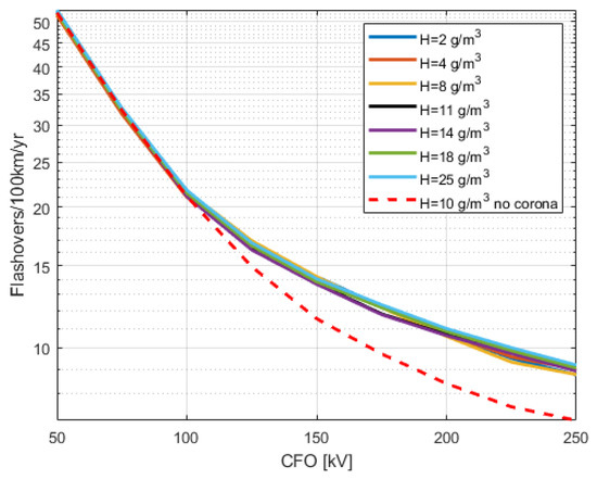
Figure 7.
Percentage variation of the number of flashovers as a function of the air humidity—the red dot line represents the case when the corona effect is not considered.
6. Conclusions
This paper analysed the importance of corona discharge in the lightning performance computation, taking into account the effect of corona discharge caused by indirect events. The corona effect has been implemented in the FDTD code for lightning-induced voltages computation following the approach proposed in Reference [12]. The number of flashovers considering the corona discharge can be compared to the ones obtained considering the finite ground conductivity, which represents a consistent part of the total. Moreover, a sensitivity analysis on the main causes leading to the corona discharge and to the enhancement of the number of dangerous events has been proposed, involving the surface state coefficient, the conductor diameter and the air humidity. The surface state coefficient variation leads to a linear percentage increase of the number of flashovers, except for very CFO values. The line diameter has a meaningful effect when we consider values lower than 20 mm: the function that better represents the behaviour of the percentage increase with respect to the diameter is exponential for CFO < 100 kV and linear for high CFO values. Finally, the effect of the air humidity is negligible. The sensitivity analysis allows an user to forecast the overall behaviour of his line with respect to the considered variables and can be taken into considerations in future IEEE Guidelines or CIGRE Working Groups Technical Brochures.
Author Contributions
Conceptualization, D.M.; methodology, D.M. and M.B.; software, D.M. and M.B.; validation, D.M.; data curation, D.M.; writing—original draft preparation, D.M.; writing—review and editing, D.M. and M.B. All authors have read and agreed to the published version of the manuscript.
Funding
This research received no external funding.
Conflicts of Interest
The authors declare no conflict of interest.
Abbreviations
The following abbreviations are used in this manuscript:
| CFO | Critical Flashover |
| EGM | Electro-Geometric Model |
| FDTD | Finite Difference Time Domain |
| GFD | Ground Flash Density |
| LIOV | Lightning-Induced OverVoltages |
| Probabilistic Density Function |
References
- IEEE Guide for Improving the Lightning Performance of Electric Power Overhead Distribution Lines; IEEE: Piscataway, NJ, USA, 2010; pp. 1–70.
- Hileman, A. Insulation coordination for power systems. IEEE Power Eng. Rev. 1999, 19, 43. [Google Scholar] [CrossRef]
- Rusck, S. Induced Lightning Over-Voltages on Power-Transmission Lines with Special Reference to the Over-Voltage Protection of Low Voltage Networks; Transactions of the Royal Intitute of Technology: Stockholm, Sweden, 1958. [Google Scholar]
- Paulino, J.O.S.; Barbosa, C.F.; Lopes, I.J.S.; Boaventura, W.d.C. An Approximate Formula for the Peak Value of Lightning-Induced Voltages in Overhead Lines. IEEE Trans. Power Deliv. 2010, 25, 843–851. [Google Scholar] [CrossRef]
- Brignone, M.; Delfino, F.; Procopio, R.; Rossi, M.; Rachidi, F. Evaluation of power system lightning performance, part I: Model and Numerical Solution Using the Pscad-Emtdc platform. IEEE Trans. Electromagn. Compat. 2016, 59, 137–145. [Google Scholar] [CrossRef]
- Brignone, M.; Delfino, F.; Procopio, R.; Rossi, M.; Rachidi, F. Evaluation of power system lightning performance—Part II: Application to an overhead distribution network. IEEE Trans. Electromagn. Compat. 2016, 59, 146–153. [Google Scholar] [CrossRef]
- Borghetti, A.; Nucci, C.A.; Paolone, M. An improved procedure for the assessment of overhead line indirect lightning performance and its comparison with the IEEE Std. 1410 method. IEEE Trans. Power Deliv. 2006, 22, 684–692. [Google Scholar] [CrossRef]
- Nucci, C. The lightning induced over-voltage (LIOV) code. In Proceedings of the 2000 IEEE Power Engineering Society Winter Meeting. Conference Proceedings (Cat. No. 00CH37077), Singapore, 23–27 January 2000; IEEE: Piscataway, NJ, USA, 2000; Volume 4, pp. 2417–2418. [Google Scholar]
- Brignone, M.; Mestriner, D.; Procopio, R.; Piantini, A.; Rachidi, F. Evaluation of the mitigation effect of the shield wires on lightning induced overvoltages in mv distribution systems using statistical analysis. IEEE Trans. Electromagn. Compat. 2017, 60, 1400–1408. [Google Scholar] [CrossRef]
- Nucci, C.A. A survey on Cigré and IEEE procedures for the estimation of the lightning performance of overhead transmission and distribution lines. In Proceedings of the 2010 Asia-Pacific International Symposium on Electromagnetic Compatibility, Beijing, China, 12–16 April 2010; IEEE: Piscataway, NJ, USA, 2010; pp. 1124–1133. [Google Scholar]
- Napolitano, F.; Tossani, F.; Borghetti, A.; Nucci, C.A. Lightning performance assessment of power distribution lines by means of stratified sampling monte carlo method. IEEE Trans. Power Deliv. 2018, 33, 2571–2577. [Google Scholar] [CrossRef]
- Nucci, C.A.; Guerrieri, S.; De Barros, M.C.; Rachidi, F. Influence of corona on the voltages induced by nearby lightning on overhead distribution lines. IEEE Trans. Power Deliv. 2000, 15, 1265–1273. [Google Scholar] [CrossRef]
- Yu, Z.; Zhu, T.; Wang, Z.; Lu, G.; Zeng, R.; Liu, Y.; Luo, J.; Wang, Y.; He, J.; Zhuang, C. Calculation and experiment of induced lightning overvoltage on power distribution line. Progress on Lightning Research and Protection Technologies. Electr. Power Syst. Res. 2016, 139, 52–59. [Google Scholar] [CrossRef]
- Agrawal, A.K.; Price, H.J.; Gurbaxani, S.H. Transient Response of Multiconductor Transmission Lines Excited by a Nonuniform Electromagnetic Field. IEEE Trans. Electromagn. Compat. 1980, EMC-22, 119–129. [Google Scholar] [CrossRef]
- Noda, T. Development of A Transmission-Line Model Considering the Skin and Corona Effects for Power Systems Transient Analysis. Ph.D. Thesis, Doshisha University, Tokyo, Japan, 1996. [Google Scholar]
- Thang, T.H.; Baba, Y.; Nagaoka, N.; Ametani, A.; Takami, J.; Okabe, S.; Rakov, V.A. A simplified model of corona discharge on overhead wire for FDTD computations. IEEE Trans. Electromagn. Compat. 2011, 54, 585–593. [Google Scholar] [CrossRef]
- Thang, T.H.; Baba, Y.; Nagaoka, N.; Ametani, A.; Itamoto, N.; Rakov, V.A. FDTD simulations of corona effect on lightning-induced voltages. IEEE Trans. Electromagn. Compat. 2013, 56, 168–176. [Google Scholar] [CrossRef]
- Brignone, M.; Mestriner, D.; Procopio, R.; Rossi, M.; Piantini, A.; Rachidi, F. EM Fields Generated by a Scale Model Helical Antenna and Its Use in Validating a Code for Lightning-Induced Voltage Calculation. IEEE Trans. Electromagn. Compat. 2019, 61, 778–787. [Google Scholar] [CrossRef]
- Brignone, M.; Ginnante, E.; Mestriner, D.; Ruggi, L.; Procopio, R.; Piantini, A.; Rachidi, F. Evaluation of lightning-induced overvoltages on a distribution system: Validation of a dedicated code using experimental results on a reduced-scale model. In Proceedings of the 2017 IEEE International Conference on Environment and Electrical Engineering and 2017 IEEE Industrial and Commercial Power Systems Europe (EEEIC/I CPS Europe), Milan, Italy, 6–9 June 2017; pp. 1–6. [Google Scholar]
- Cooray, G.V. The Lightning Flash; IET: Stevenage, UK, 2003. [Google Scholar]
- Hartmann, G. Theoretical Evaluation of Peek’s Law. IEEE Trans. Ind. Appl. 1984, IA-20, 1647–1651. [Google Scholar] [CrossRef]
- Bousiou, E.I.; Mikropoulos, P.N.; Zagkanas, V.N. Corona inception field of typical overhead line conductors under variable atmospheric conditions. Electr. Power Syst. Res. 2020, 178, 106032. [Google Scholar] [CrossRef]
- Heidler, F.; Cvetic, J.M.; Stanic, B.V. Calculation of lightning current parameters. IEEE Trans. Power Deliv. 1999, 14, 399–404. [Google Scholar] [CrossRef]
- Anderson, J. Lightning Performance of Transmission Lines; Electric Power Research Institute: Palo Alto, CA, USA, 1981. [Google Scholar]
- Darveniza, M. A practical extension of Rusck’s formula for maximum lightning-induced voltages that accounts for ground resistivity. IEEE Trans. Power Deliv. 2006, 22, 605–612. [Google Scholar] [CrossRef]
- Kuffel, J.; Kuffel, P. High Voltage Engineering Fundamentals; Elsevier: Amsterdam, The Netherlands, 2000. [Google Scholar]
© 2020 by the authors. Licensee MDPI, Basel, Switzerland. This article is an open access article distributed under the terms and conditions of the Creative Commons Attribution (CC BY) license (http://creativecommons.org/licenses/by/4.0/).