Review

Magneto-Rheological Elastomer Composites. A Review

1
FZU-Institute of Physics of Czech Academy of Sciences, Na Slovance 1999/2, 18221 Prague, Czech Republic
2
Institute for Nanomaterials, Advanced Technologies and Innovation, Technical University of Liberec, Studentska 2, 461 17 Liberec, Czech Republic
3
Department of Physical and Chemical Methodologies for Engineering, University of Catania, Viale A. Doria 6, 95125 Catania, Italy (Retired Professor)
4
Department of Civil Engineering and Architecture and UdR-Catania Consorzio INSTM, University of Catania, Viale Andrea Doria 6, 95125 Catania, Italy
*
Author to whom correspondence should be addressed.
Appl. Sci. 2020, 10(14), 4899; https://doi.org/10.3390/app10144899
Submission received: 1 July 2020 / Revised: 13 July 2020 / Accepted: 15 July 2020 / Published: 17 July 2020
(This article belongs to the Special Issue Synthesis, Characterization and Application of Hybrid Composites)

Abstract

:
Magneto-rheological elastomer (MRE) composites belong to the category of smart materials whose mechanical properties can be governed by an external magnetic field. This behavior makes MRE composites largely used in the areas of vibration dampers and absorbers in mechanical systems. MRE composites are conventionally constituted by an elastomeric matrix with embedded filler particles. The aim of this review is to present the most outstanding advances on the rheological performances of MRE composites. Their distribution, arrangement, wettability within an elastomer matrix, and their contribution towards the performance of mechanical response when subjected to a magnetic field are evaluated. Particular attention is devoted to the understanding of their internal micro-structures, filler–filler adhesion, filler–matrix adhesion, and viscoelastic behavior of the MRE composite under static (valve), compressive (squeeze), and dynamic (shear) mode.

1. Introduction

Magneto-rheological elastomer (MRE) composites belong to the category of smart materials, showing a fast (milliseconds) and reversible transformation, including a controllable stiffness and frequency-dependent viscoelastic behavior, when subjected to a magnetic field [1]. Such composites generally show variations in magneto-rheological (MR) effect for applying in magnetic flux densities of the order of magnitude of 0.8 T [2]. The conventional use of MR fluids creates the settling of particles within the matrix as the function of time. To solve the issue of sedimentation of particles, MR elastomer emerges as an alternative polymer for the MRE composite [3]. The properties could be influenced by the function of temperature. Figure 1 is a schematic representation about the role of temperature for the transformation of MR fluids to elastomer [4]. The MR effect in the composite opens a considerable property making them suitable for the application in mechanical systems where the active control of vibrations or transmission of torque are required. Such as in the areas of tunable vibration absorbers, shear type dampers, composite dampers, isolators, seismic vibration dampers, brakes, control valves, clutches, and artificial joints [5,6]. Furthermore, application fields using the magnetic control are those related with the thermal energy transfer, sound propagation, and isothermal magnetic advection, until you get to the biomedical applications [7,8]. Similarly, magnetic nanocomposites find important applications in the areas of remediation, catalysts, and microwave absorbers in response to external stimulus [9]. In addition, other than elastomeric polymers, current research also focuses on biocompatible and thermoresponsive polymers in the fabrication of magnetic field responsive composites [10].
Conventional MRE composites consist of two-phase matters obtained by dispersing magnetizable micron-sized solid particles in a liquid matrix, up to 30 vol %. Due to their considerable saturation magnetization (µ0Ms = 2.1 T), iron and carbonyl iron particles are commonly used to this purpose, whilst silicone oils are employed as carrier liquids. Additives are necessary to inhibit sedimentation and aggregation of filler particles within the matrix, in addition, they provide lubricating properties [11]. Silicone rubber, one of the most common elastomers, is used a as matrix consisting of two-phase liquids with base/binder in the 1:1 ratio. Generally, in the composites fabrication after the adding of the magnetic particles into the matrix, a curing is carried out either in the absence (isotropic MREs) or in the presence (anisotropic MREs) of an external magnetic field. The efficiency of the MRE composite, oxidative and chemical stability, and durability, strictly depends on various factors, among those, particles aggregation plays a key role, considering that the interface particles-matrix is determinant in the durability of the composite [12,13]. Thus, in designing MRE composites the main purpose is to obtain the highest MR effect, by inducing magnetization of the particles used as filler [14]. In fact, when the magnetic field is not present, it is possible to observe a random distribution of the particles within the matrix; thus, leading to an isotropic composite. Differently, the presence of a magnetic field, during the preparation, leads to the particles magnetization and attracting one another along the field lines, with the formation of an anisotropic aggregate that spans the system. The so obtained composite shows high yield stress and a large shear rate-dependent apparent viscosity, with increase in viscoelasticity due to the applied magnetic field. The magnetically induced shape change, because of the MRE based magnetostrictive sensors, is very effective with relatively soft materials. This effect, the so-called magnetostriction effect, is due to the decrease of the deformation (ε) as a function of the inverse square root of the elasticity modulus (E), (ε~E−1/2). Classic elastomer composites, with reinforcing fillers, are prepared by exploiting the long chains cross-linking during the curing process. Generally, the above reported effect is very low for stiff elastomer composites, but the application of an external magnetic field can contribute to a considerable increase of the MRE’s elastic modulus, up to 30%. As reported in literature by Mehnert at al., this affects the resonance frequency and the damping behavior of the adaptive components [15]. The mechanism of materials magnetization is described in Figure 2.
The metal particles used as fillers for the MRE composites greatly affect their properties; thus, saturation magnetization and magnetic coercivity result key parameters for the adoptive components. Considering the easy reversibility of the magnetization direction, the energy dissipation in an alternating magnetic field is very low. At the same time, when an external magnetic field is applied, the particles magnetization and the magnetic flux density of the composite increase, and as a result interaction between neighboring particles increases. The MRE’s triggering occurs at the application of the external magnetic field because the magnetization of the fillers lead to a rapid and stepwise change in magnetic flux. Among the adjacent magnetic particles dipole–dipole interactions are generated which stiffens the matrix; thus, forcing the fillers to arrange themselves in a columnar structure. This particular particle distribution is easily reached when a magnetic field is applied during the curing process. This distribution effect determines the MREs composite’s switching ability and, since stiffness and hysteresis behaviors depend on the magnetic orientation, an anisotropic composite can be easily prepared by exploiting this behavior. The energy interaction of the magnetic particles (EMI) increases as a function of the magnetic dipole moment square, and decreases with the third power of the average distance among the adjacent fillers E M I = V p 2 / r 3 .
The particle volume fraction (ф) and the average distance (r) varies linearly with their diameter according to the following equation:
r = d ( π 6 ) 1 / 3
Accordingly, EMI increases linearly as a function of the particle volume; thus, indicating a strict correlation among the magneto-rheological response of the whole sample and the filler’s volume, so that the switching effect increases by increasing the particles size.

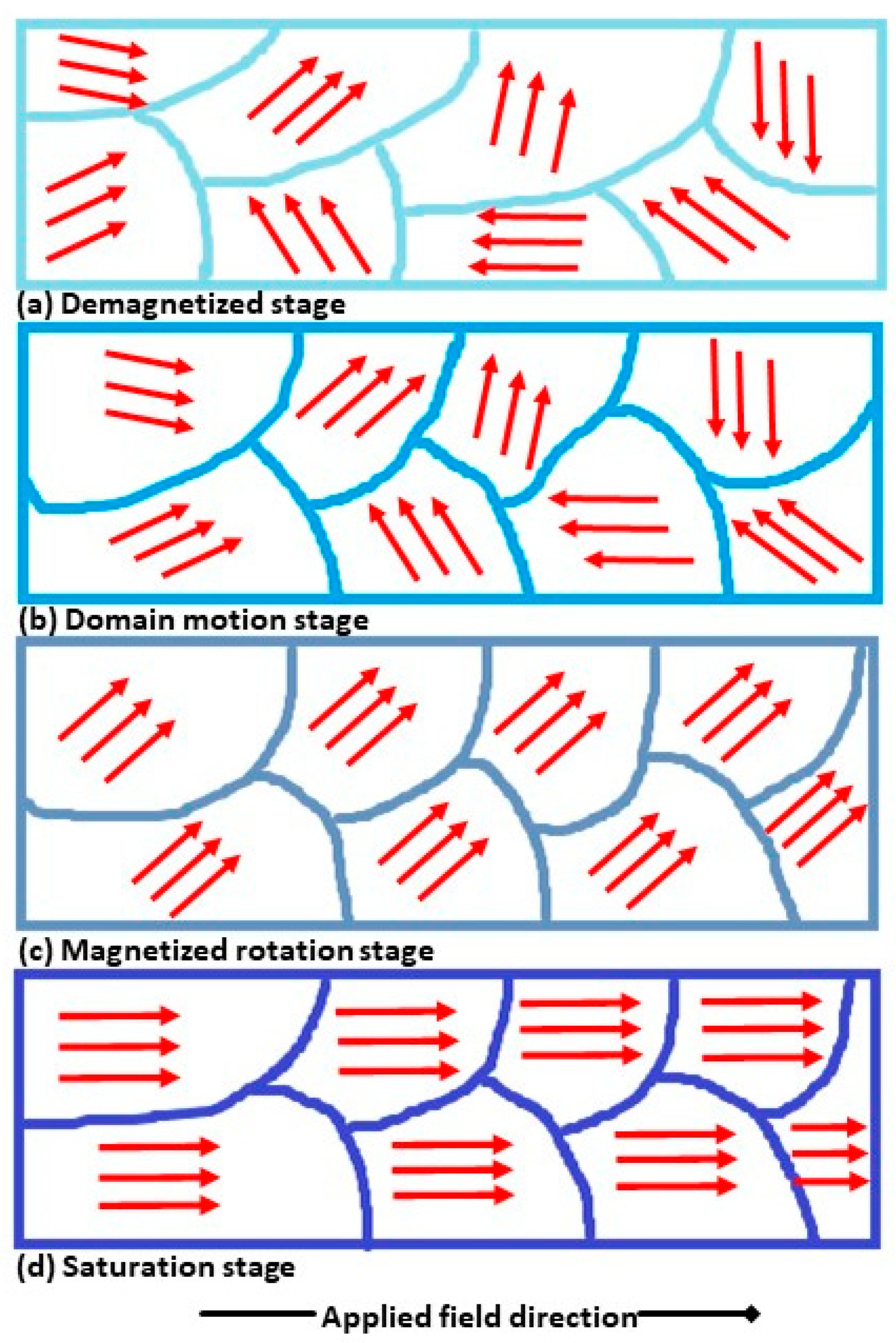
1.1. Physical Static Mechanism of MR Effect

Coupling the MR’s magnetization with the anisotropic interaction we obtain the “particle magnetization model”, which attributes the MR effect to the magnetic permeability mismatch among the constituent phases, both the continuous and dispersed one. Considering the solid phase as the magnetic one, it could be possible to observe that the larger size particles behave as magnetic multi-domains. Considering the particle’s magnetic moment is field-induced, their Brownian motion is neglectable; furthermore, the solvent thermal forces (∝ KT) are generally much smaller than magnetic and hydrodynamic ones.
A simplified model could have been achieved by neglecting multibody and multipole magneto static interactions among filler molecules. The magnetic moment of a particle with single domain and magnetizable sphere of radius, in a linear magnetization regime, is
m = 4 π μ 0 μ c r β a 3 H 0
where μ0 is the permeability of the vacuum and is equal to μ 0 = 4 π × 10 7 T m A 1   ,   μ cr is the relative permeability of the continuous phase, and β is the contrast factor or coupling parameter β = μ p r   μ c r / μ p r +   2 μ c r , μpr is the relative permeability of the particles, and H0 is the magnetic field strength. Contrariwise, at higher magnitude, the particle magnetization saturates and the magnetic moment becomes independent of the field strength:
m = 4 3 π μ 0 μ c r α 3 M s
In a linear regime, the interaction energy’s magnitude between two magnetic moments is
λ = π μ 0 μ c r β 2 α 3 H 0 2 2 k B T
where 0 < β < 1 for strong MR fields (conventional conformation), and 0.5 < β < 0 for weak MR fields (not conventional conformation). The magnetostatic particles interaction dominates overall thermal motion in case of chain-like particle aggregates. The particles movement within the elastomer during fabrication of MRE composite results in kinetic aggregations into two different regimes. Firstly, the aggregates average length increases as a power law, then single width chain-like structure laterally aggregate forming columnar structures. Thermal fluctuations of particles in position correlate to their mechanism of lateral aggregation. Iron particles based MRE composite show coarsening defect of tip-to-tip stage of aggregation, leading to a local variation in the magnetic field surrounding to the chain-like structure. The lateral interactions between dipolar chains play an important role in the isotropic structure of MRE samples. In the MREs, the elastomer shows steady shear flow, as a result, the Mason number (Mn), is basically dimensionless; thus, shear rate can be defined as the ratio between the hydrodynamic drag and the magnetostatic forces (estimated as the dipole force magnitude) acting on the particles [16].
M n = 8 η c γ ˙ μ 0 μ c r B 2 H 2
ηc is the continuous phase viscosity and γ ˙ is the magnitude of the shear rate tensor. MR vulcanized elastomer behave as Newtonian fluids in the absence of a magnetic field, whilst if a magnetic field is applied transverse to the direction of flow, it is possible to observe a yielding, shear, and viscoelastic behavior.
Yield stress is based on macroscopic and microscopic models. Macroscopic models employ minimum magnetic energy distribution that leads to homogenous structures of MRE composite reinforced with fillers such as spherical or layered particles in aggregates. This model contributes towards shear anisotropy of the strained aggregates under small deformation. Contrariwise, microscopic models treat inter-particle interactions, such as single particle chains sheared under an external magnetic field. The particle’s magnetostatic interactions dominate the shear stress, and shear-induced deformation is assumed to be affine; thus, the magnetic field strengthens the network without affecting its shape significantly. Micro mechanical chain-like models are based on the balancing of magnetostatic and hydrodynamic forces. MRE system shows linear viscoelasticity when subjected to small strains. Instead, high order harmonics define the critical strain; thus, sanctioning the transition from the linear to the non-linear viscoelastic regime. Then, larger strain amplitudes define the second critical strain with a transition from the nonlinear viscoelasticity to viscoplasticity. In the presence of a magnetic field, and thus of a field-induced structure, it is possible to observe a storage modulus (G′), generally of an order of magnitude greater of the loss modulus (G″). At completely saturation of the particles magnetization, in the presence of a large field strength, G′ is independent by this field strength, G′ = 0.3 фµ0Ms2.

1.2. Dynamic of MRE

Dynamics of MRE are considered from the shear deformation for a linear viscoelastic material. The dynamic behavior is represented with a complex modulus related to the vibration frequency and controllable by external magnetic fields. The dynamic model or MRE’s constitutive relationship [17] is given by
i = 0 n 1 a i i τ t i = k = 0 n 2 b k k γ t k
where τ and γ represent the MRE’s shear stress and strain, respectively; ai and bk are the constant coefficients dependent on external magnetic field strength; and n1 and n2 are integers. Considering the periodic harmonic strain and stress, the equation becomes
τ = = [ e j θ k = 1 n 2 b k ( j w ) k i = 1 n 1 a i ( j ω ) i ] γ ¯ = G ( j ω ) γ =
where τ = = γ ¯ e j ω t , τ = τ ¯ e j ( ω t θ ) , with γ ¯ and τ ¯ being amplitudes of stress and strain, respectively. j = 1 , ω is the vibration frequency, θ is the delayed phase between stress and strain, and G(jω) is a complex modulus that is a function of vibration frequency ω and MRE’s external magnetic field strength. The real part of the complex modulus G R ( ω ) is the storage modulus representing the viscoelastic stiffness. The imaginary part G I ( ω ) is the loss modulus, with the ratio of loss to storage modulus, represented by the loss factor, describing the viscoelastic damping:
Δ w = G ( ω ) I G ( ω ) R
The differential equation in Equation (6) is very difficult to solve for MRE systems. Therefore, the Equation (7) is commonly used to describe the MRE’s dynamic stress–strain relationship. Experimental evidence shows mostly a linear increase of the storage modulus as a function of the vibration frequency, and both the storage and the loss modulus linearly increase with the external magnetic field strength in a certain range. Hence, the storage modulus G R ( ω ) and the loss factor Δ(ω) can be expressed approximately by:
G R ( ω ) = α 0 + α 1 ω
Δ ( ω ) = β 0
with   α 0 , α 1 and β 0 depending only by the applied magnetic field strength.

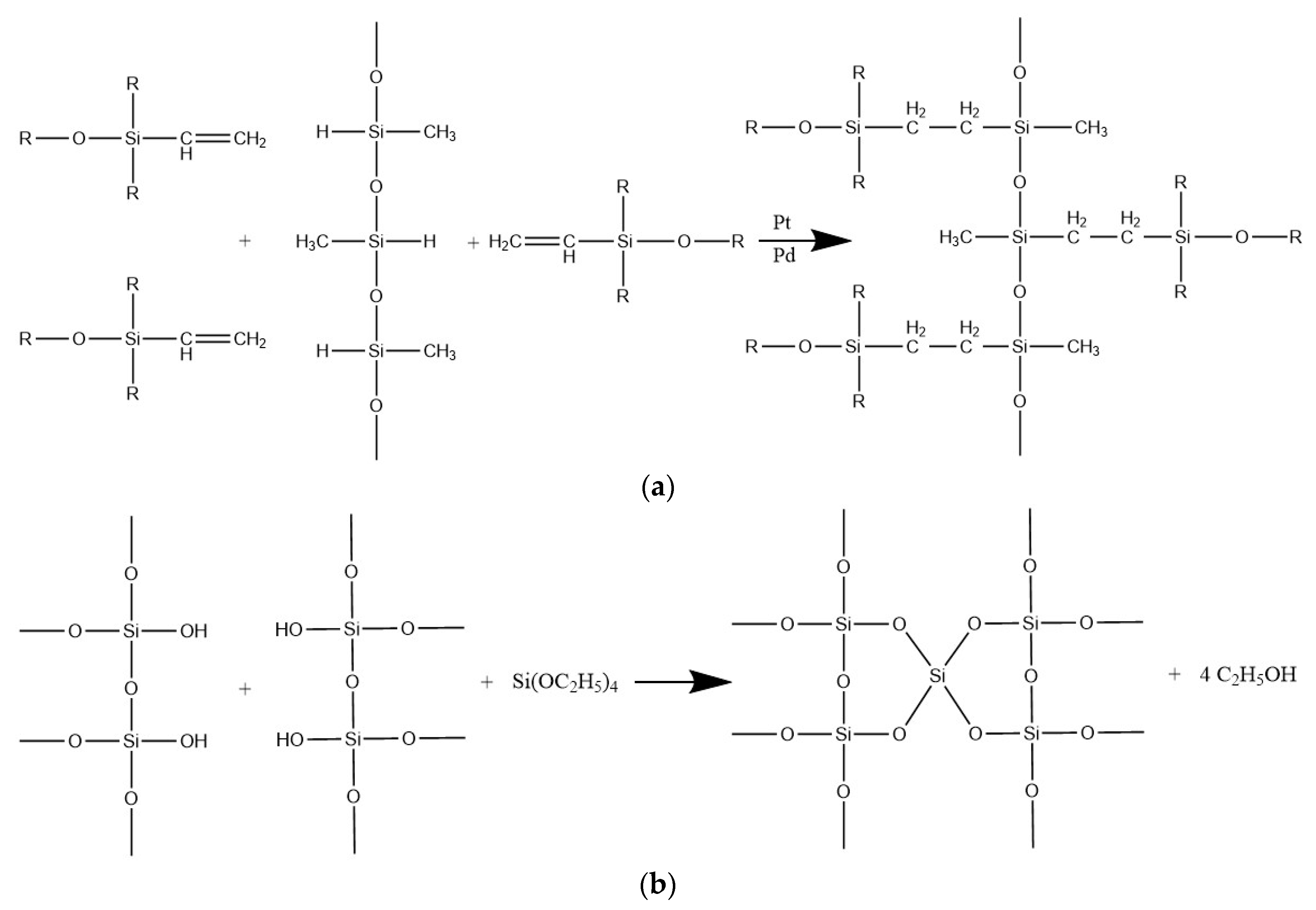
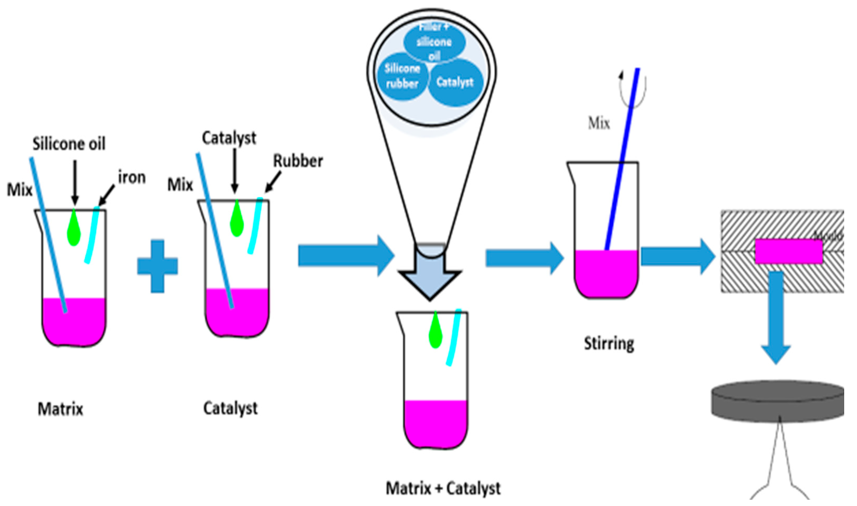
2. Materials and Methods

We take into consideration a MRE composite prepared by mixing 30 vol % of iron and carbonyl iron particles in silicon elastomer matrix [18]. This latter was prepared from the combination of matrix/binder in the ratio of 50:50 in quantity. The iron particles incorporated into silicon elastomer had a size of 50–100 µm and purity > 95%. The used matrix was obtained by polyaddition, ZA 22, and by polycondensation, N 1522. The carbonyl iron was only considered in the matrix of ZA 22 (Figure 3).
In order to improve the particle’s adhesion on the matrix surface, we used silicon oil. Therefore, particles treated with silicon oil, matrix, binder, and catalyst were slowly stirred, at room temperature, until homogenization (ca. 30 min). The obtained mixture was then treated under vacuum for removing air bubbles and then cured in the standard mold (ca. 24 h), without any influence of the magnetic field. Cylindrically samples were designed, with a length of 20 mm and a radius of 5 mm. The anisotropic composites were prepared using magnetic field along the perpendicular direction of the sample during curing time (Figure 4) [18].
The induced magnetic field was applied perpendicularly to the sample thickness during the static and compressive mode. However, the closed domain of the magnetic field was applied parallel to the sample position during shear or dynamic mode. Therefore, both the magnetic intensity and the sample orientation in the magnetic field have been set up. As shown in Figure 5, the MRE composite was put in contact with the copper slabs of the magnetic field circuit, both with its upper and lower surface. The simulation was performed by the means of MSC MARC, non-linear dynamics Software (Newport Beach, CA, USA). The simulation parameters were carried out at the boundary conditions of the magnetic potential and current of 1 A. After this test, SEM and µCT analyses were carried out on the MRE composites.
A Hitachi TM-3000 (Hitachi High-Technologies Corporation, Tokyo, Japan) with a secondary electron detector and field emission source was used to perform scanning electron microscopy. Sample fragments were assembled on aluminum stubs, out-gassed in a desiccator (ca 48 h), and then coated with a 4 nm layer of platinum before SEM imaging. An acceleration voltage of 10 kV was used in SEM analyses. The µCT analysis was carried out, in sky scan mode with 3D reconstructed images from slices of the two-dimensional structure, on an open tube source with Tungsten (Bruker, R.M.I. s.r.o., Lázně Bohdaneč, Czech Republic). The instrument setting and the measurement parameters are reported elsewhere [20,21,22]. Various modes of operation of magneto rheological elastomeric composite are tested in static, compressive (deformed), and dynamic (shear mode), to observe the effect of various magnetic flux density and the hysteresis behavior from force versus displacement response. Static and dynamic properties of MREs composite, of isotropic and anisotropic filler distribution, were investigated as a function of the magnetic intensity, frequency, strain amplitude, and damping properties in various modes [23]. The schematic diagram of the static and compressive (deformed mode) is shown in Figure 5 and Figure 6.

3. Results and Discussion

3.1. Simulation Mechanism of MRES Composite and Magnetic Flux Distribution

The magnetic flux distribution from the magnet towards MRE composite has been carried out using simulation method. Figure 7 shows the distribution of the magnetic induction in the system of the magnetic field with MRE included.
The enclosed magnetic circuit records minimum energy losses due to the formation of a field path for the magnetic flux. In order to remove these energy losses, we need to maintain the gap between the two poles of the C-shape magnetic circuit as small as possible. This configuration allows for a uniform and strong magnetic field. As reported in Figure 8, the future MR elastomer devices require an increase in efficiency and compactness when designing magnetic circuits design; thus, launching a new challenge. For this reason, a different C-shape design in length and scale of components, such as coil and conductive path, is required [24].
The first configuration is characterized by the presence of the field-sensitive material outside the magnetic coil with the material’s motion direction parallel to the coil’s axis. Thus, because of the field direction requirement, only small sections of MRE composite in the active area exhibit MR effect. In the second type of magnetic circuit configuration, to make the most of the magnetic field, the MR materials were attached on the surface of the coil, closely placed on the top or/and the bottom of the solenoid. This latter configuration was adopted in most of the MR elastomer-based vibration absorbers and isolators designs. The third configuration consisted in placing the MR materials inside the magnetic coil: thus, serving as the magnetic core of the circuit. In fact, the magnetic field inside the solenoid was strong and uniform, different to the one outside the coil, which was weak and divergent. The greatest advantage of the third configuration was represented by the strong magnetic field generated as well as a large active area. Despite the MR materials inside the solenoid being able to be fully energized by a uniform magnetic field, special care must be given due to the permeability of the magnetic core because of the low permeability of the elastomer component of the MR material. Liu et al., by using MR elastomer, reported about a squeeze mode configuration used in tunable spring element [26]. They applied the elastomer, with compressive loading, in the direction aligned with the magnetic flux. Thus, to enhance their stiffness, most of the MR elastomer devices use the magnetic field. To realize negative stiffness, a hybrid magnetic design for the MR elastomer devices has been used. In Figure 9 shows a tunable vibration absorber, designed by using both a permanent magnetic and an electromagnetic coil for field generation.
In such configuration, it is possible to enhance or weaken the magnetic field, by applying positive and negative current, towards the field generated by permanent magnetics. The resonant frequency of the device can be controlled by electrical currents from 55 Hz at 0 A to 81.25 Hz at 1.5 A, which is equivalent to an increase of 147%. Contrariwise, for an applied current of 1.0 A, the magnetic field decreases from 0.58 to 0.56 T (9% decrease).
An anisotropic MR elastomers design, with an iron particle mass ratio of 70%, is particularly valuable when certain stiffness is required for the device to maintain the serviceability and stability of the structures [27].
In Figure 10 an MRE composite in shear mode is shown, consisting of a particular design using a closed magnetic circuit, which was built with low-carbon steel parts, a wired coil for field generation and two anisotropic MR elastomers. In order to allow vertical motion, the reaction mass was placed among these two samples. Furthermore, to strengthen the magnetic field, the direction of the coils was arranged in an opportune way. Such design was realized by using anisotropic MR elastomers with 30 vol % of iron particles. This design focus on combining both shear and squeeze mode for the application of the MR elastomer device [28].

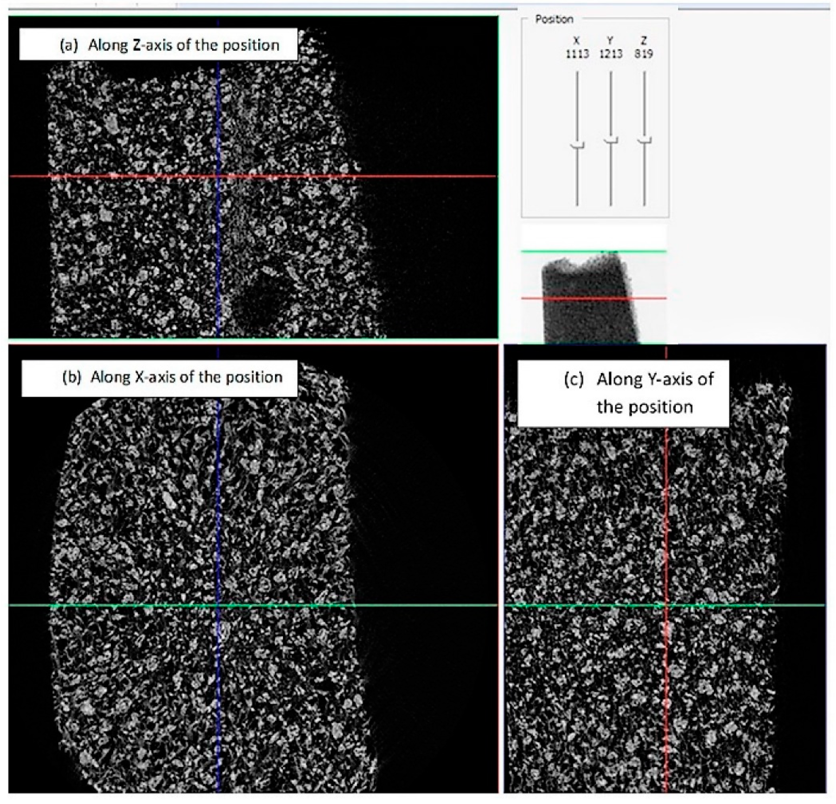
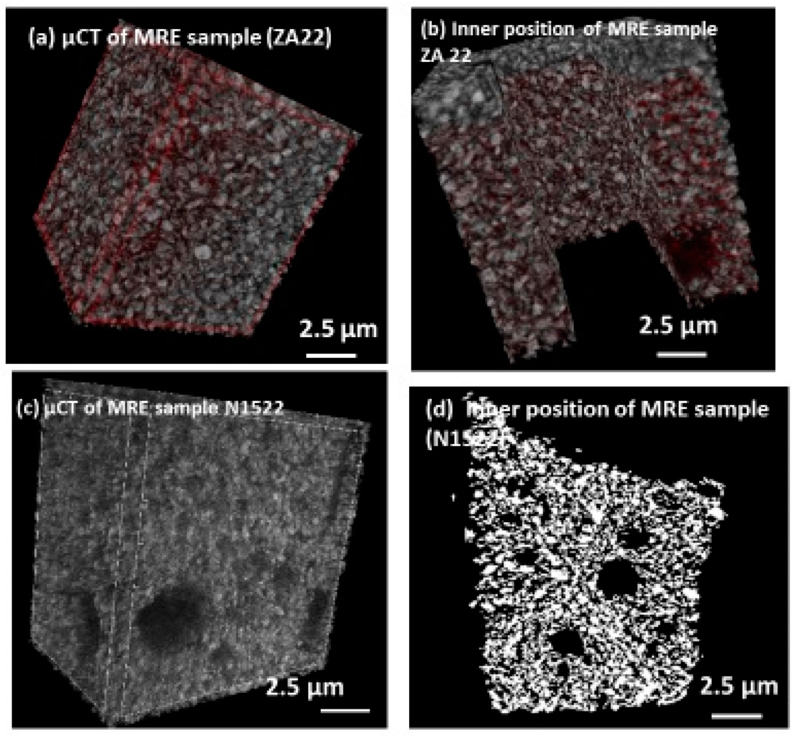
3.2. Surface Characterization Using SEM and µCT Technique

Based on the filler particles distribution, isotropic and anisotropic MREs composite were characterized by surface morphology. Filler–matrix adhesion was investigated to verify the quality of the composite. The attachment of iron particles within the elastomer matrix was examined using both microscopy and internal volume of the composite [29].
The iron filler surface morphology displayed irregular surface features with filler distribution from 20–120 µm size (Figure 11a,b). The elastomer matrix and its respective MREs composites with fibril self-assembled structures are represented in the surface features (Figure 11c–f). The smaller particles show better adhesion in comparison to the larger ones. The adhesion of filler particles iron towards elastomer matrix is shown in Figure 11g,h. The distribution shows the random orientation of the filler particles within the elastomer matrix that leads to the isotropic distribution of the composite. As a result, the effect of the external magnetic field in isotropic MREs composite led to the magnetization of the small fragments generated during the self-assembled structure of the composite. The small fibrils generate magnetization force based on the particles spin orientation for the application of MRE composite [30,31]. However, the effect of magnetization was more prominent in the anisotropic MRE composites. During the preparation of the composite, the fillers showed a chain-like arrangement due to curing and locking pattern created in the presence of the external magnetic field. Similarly, anisotropic filler distribution in the MRE composite showed parallel chains of fillers along with the matrix of the composite during preparation in the presence of an external magnetic field. Anisotropic distribution of filler within the elastomer composite is shown in Figure 12.
Filler matrix adhesion induce a good wettability in the MRE composite that leads towards self-assembled particle–particle short fibrils network structure. The volumetric distribution of the particles within the elastomer matrix of the MREs composite was investigated by micro-computed tomography (µCT). This technique reveals a slice of MREs composite in the 2D frame as well as in 3D reconstructed images from all various slides of the composite (Figure 13).
3D images were rebuilt from the various rotation angles of the composite and observed overall in volume fraction to examine their inner structure. This technique and image construction significantly reveal the closed and open pores within the volume and filler distribution in the various directions. The 3D images show one slice and overall images of the MRE composite with iron filler distribution, including the open and closed porosity in the whole structure.
Figure 14a,d displays the inner quality of the MRE composites in 3D planes. The whole volume of the MRE composites in shown in Figure 14a,c. The cut-up layer of the inner volume is shown in Figure 14b,d. This means a qualitative analysis of the composite with, and without, porosity in volume. Quality of the MRE composite is derived from the thermal and rheological behavior of the matrix during curing [32,33].

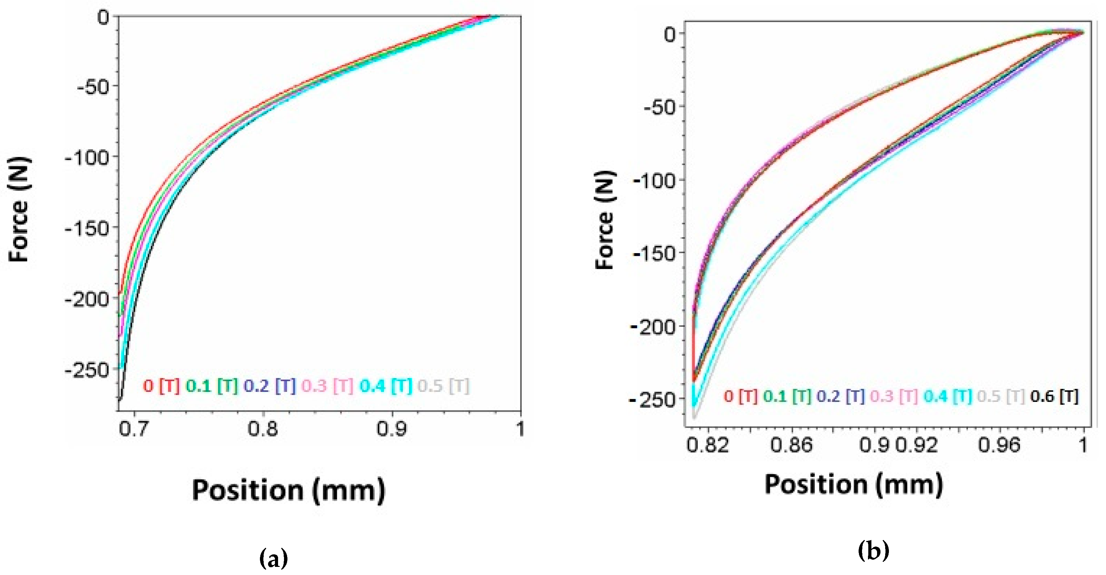
3.3. Static Characterization of MREs Composite, Single Field Active, Deformation (Squeeze) Mode

Elastomers exhibit Mullin effects from the results of evolution in the hard and soft domain microstructure induced by stress [34,35]. All MRE composites show a more or less pronounced Payne effect; i.e., the storage modulus decreases with increasing the strain due to the filler network breakdown. Thus, the in-rubber structure determines the strain–independent part of the modulus as a combination of polymer network, the contribution from the hydrodynamic effect, and the modulus [36,37].
MRE samples with isotropic filler distribution undergo mechanical testing in the presence of a magnetic field in a single field and squeeze mode of deformation using the domain of the magnetic field (Figure 4 and Figure 5). The deformation mode of the MRE sample shows hysteresis at various magnetic flux intensities. It has been observed that on increasing the flux intensity of 0.5 T, the area under hysteresis curve increases showing the influence of magnetic domain in the MRE sample behavior (Figure 15).
The maximum intensity of the magnetic domain 0.3 (T) shows the behavior of MRE composite and its response towards recovery to the initial position. The recovery of deformation is investigated by the single and double domains compression test and plotted as load versus position of the sample at various magnetic field intensities. The hysteresis response of the MRE composite and its deformation recovery in the presence of a magnetic field could open up the possibilities for their use as sensors and dampers.

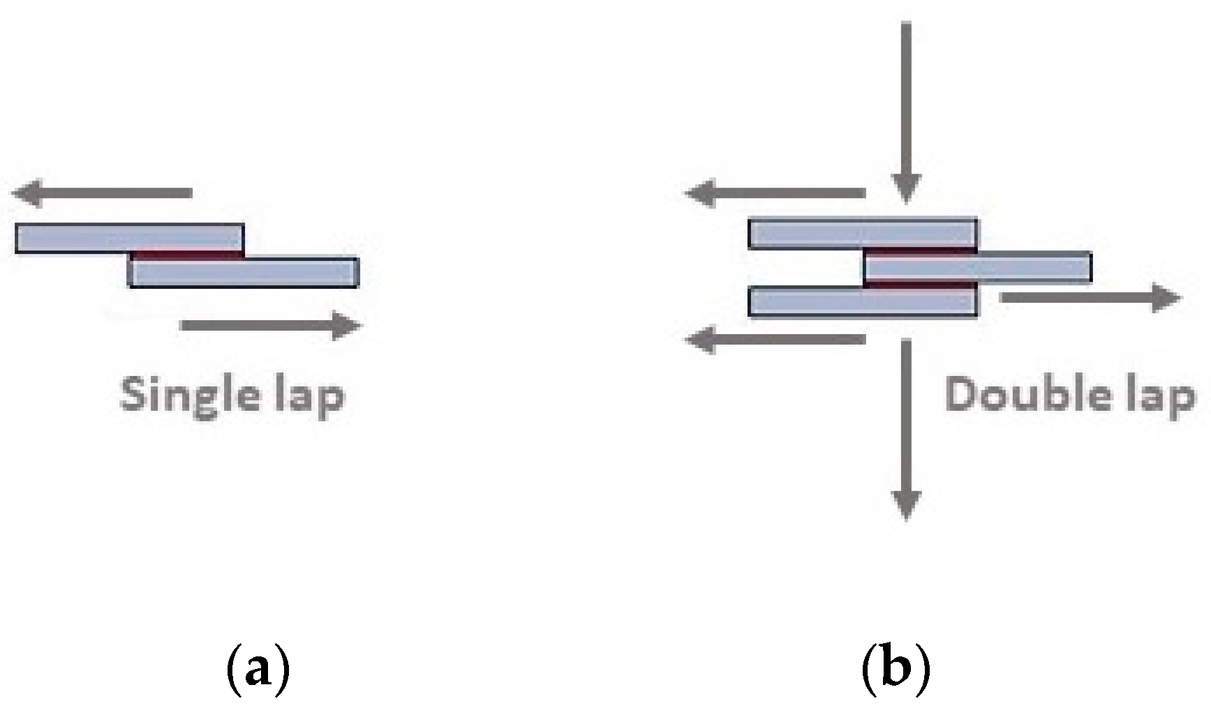
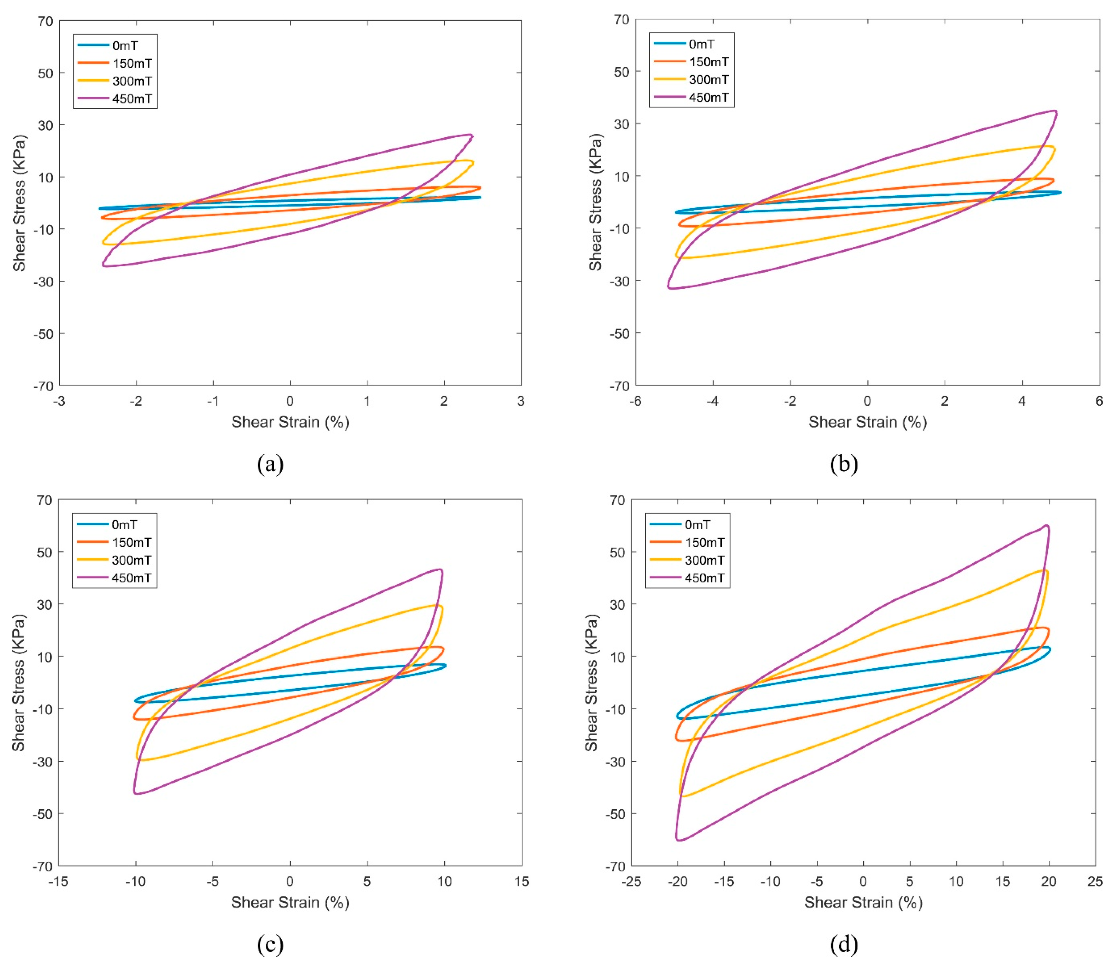
3.4. Dynamic Characterization (Shear Test, Single, and Double Mode)

Dynamic characterization relates with damping behavior of MREs in a magnetic field. Effect of amplitude and frequency control the damping behavior of MREs in the presence of magnetic domain. Single and double lap shear test were implemented on single and double MRE samples with sandwich panel mode. Single lap shear test uses under the shear test for the response of dynamic properties of MRE sample under magnetic domain. The schematic presentation of single and double lap shear test is shown in Figure 16.
The effect of magnetic flux density on the measured stress–strain hysteresis loops for MRE, at different strain amplitude at 10 Hz (a) 2.5%, (b) 5%, (c) 10%, and (d) 20%, as the function of shear strain are reported in Figure 17 showing the strong correlation of the magnetic flux density effect and vol % of filler towards the shear behavior of the MRE composite.

4. Future Prospectus on the Applications of MREs Composite

MRE composites have opportunities in the field of elastomer devices in practical way of engineering applications. MRE composites under tension, compression, and shear test shows possible uses in the application areas of vibration isolation and absorption capacities. Combined approach of shear and compression test may allow application in the area of sensing of elastomer devices. MR elastomer devices include large adaptive working frequency range, low power consumption, and compact configuration. Thus, given a sufficient magnetic field is provided, devices with large changes in their modulus and damping (i.e., MR effect), between field-on and field-off status, can offer a great adaptive range. Effect of filler size, shape, and nature of the matrix has a significant role in the quality of MREs composite. The volume fraction of 30% of filler particles are considered to be optimized for significant distribution of fillers within the matrix. The circular and smaller particles such as carbonyl iron with higher magnetization contribute maximum MR effect in the MREs composite. Soft elastomer matrix such as rubber matrix could be considered as a most suitable one; however, the vulcanization time is longer that may hinder the durability of the devices.
Several cross-linking systems such as sulfurs, organic peroxide, phenolic resins, amino acids, ultrasonic waves, and microwaves have been used for the rubber vulcanization. Among these sulfur and peroxides are the most widely used in the vulcanization process. The mechanism of the accelerated sulfur vulcanization is still controversial partly due to the complexity of the formulation. Therefore, the need to consider the trade-off among MR effects and other performance criteria should be carefully considered for these elastomers. Their application in civil engineering structures, especially for base isolation systems, has recently attracted increasing attention towards adaptive base isolators made of MREs composite.
A decrease in the storage modulus as a function of the strain increase, when the filler network is subject to a breakdown, the so-called Payne effect, is shown by all MRE composites, some by more and some by less. In particular, the isotropic MREs show, at low particles content, a systematic decrease in the small-strain storage modulus G′ [38,39]. By contrast, an increase of the small-strain storage modulus G′ is generally recorded for the anisotropic MREs. With 30% particle content, anisotropic MRE composite change was more pronounced for the storage modulus (20.4%) than for the loss modulus (8.8%), both changes were determined at 30 Hz with the maximum applied magnetic field being about 0.775 T. This behavior is explained with the magnetized particle arrangement in anisotropic strings during the curing process. The new arrangement that contributes to the stiffness of the compound. Just the micro-sized iron particles, with high saturation magnetization, show a considerable orientation effect within a magnetic field. In fact, due to their large magnetic moment, they generate strong attractive dipole–dipole interactions when the magnetic field is applied [40,41]. Furthermore, close contact is also decisive to get these dipole–dipole interactions in the magnetic field [42]. MRE’s devices are generally classified into two categories, those having either fixed poles (pressure-driven mode) and those having relatively moveable poles (direct-shear mode and squeeze-film mode). The first category includes servo-valves, dampers, and shock absorbers, whilst the second one includes clutches, brakes, chucking, and locking devices. A third mode of operation, also known as biaxial elongation flow mode, appears in slow motion and/or high force applications.

5. Conclusions

MRE composites with improved mechanical properties were designed and prepared by using different magnetic fillers at different sizes with, varying composition and keeping constant (i.e., 30 vol %) the total fillers volume fraction. Vulcanization has been carried out, in the presence of an external magnetic field, to obtain anisotropic MREs, and thus improving the magneto-rheological behavior of the composites. Since the viscosity of the polymer matrix is strongly reduced during curing at high temperature, the mobility of the particles used as filler is increased. Therefore, the particles can move readily in the presence of a magnetic field, influencing the distribution of the magnetic filler in the polymer matrix. Non-crosslinked samples were investigated by magneto-rheological viewpoint, showing particles alignment into strings, which was attributed to the strong magnetic dipole–dipole interactions within the micro-sized filler. Various modes of application in the MRE field are discussed that may lead to the application in engineering fields. The surface morphology and inner structure of the MRE composite with filler-polymer, filler–filler adhesion is configuring from 3D structure. This special microstructure allows the preparation of samples with improved shear stiffness and a magnetically conductive filler network highly sensitivity for magneto-rheological applications.

Author Contributions

S.S. and M.Š. conceived and designed the study; discussion on article write up and necessary modifications were carried out by all the authors in a team effort. I.B. and L.A. has revised the manuscript briefly. L.A. corrected the manuscript and prepared the formatted version in text and figures. All authors have read and agreed to the published version of the manuscript.

Funding

This work was carried out within the Institute of Physics and Institute of Plasma Physics under the Solid-21 project (SOLID21: CZ.02.1.01/0.0/0.0/16_019/0000760, SOLID21-Fyzika pevných látek pro 21. Století, Fyzikální ústav AV ČR, v. v. i. (2018–2023). Ignazio Blanco is grateful to the University of Catania within the “Bando-CHANCE” n° 59722022250, for supporting the project HYPERJOIN-HYBRID HIGH PERFORMANCE INNOVATIVE JOINTS.

Conflicts of Interest

The authors declare no conflict of interest.

References

  1. Li, Y.; Li, J.; Li, W.; Du, H. A state-of-the-art review on magnetorheological elastomer devices. Smart Mater. Struct. 2014, 23, 123001. [Google Scholar] [CrossRef]
  2. Zhang, J.; Pang, H.; Wang, Y.; Gong, X. The magneto-mechanical properties of off-axis anisotropic magnetorheological elastomers. Compos. Sci. Technol. 2020, 191, 108079. [Google Scholar] [CrossRef]
  3. Samal, S. Effect of shape and size of filler particle on the aggregation and sedimentation behavior of the polymer composite. Powder Technol. 2020, 366, 43–51. [Google Scholar] [CrossRef]
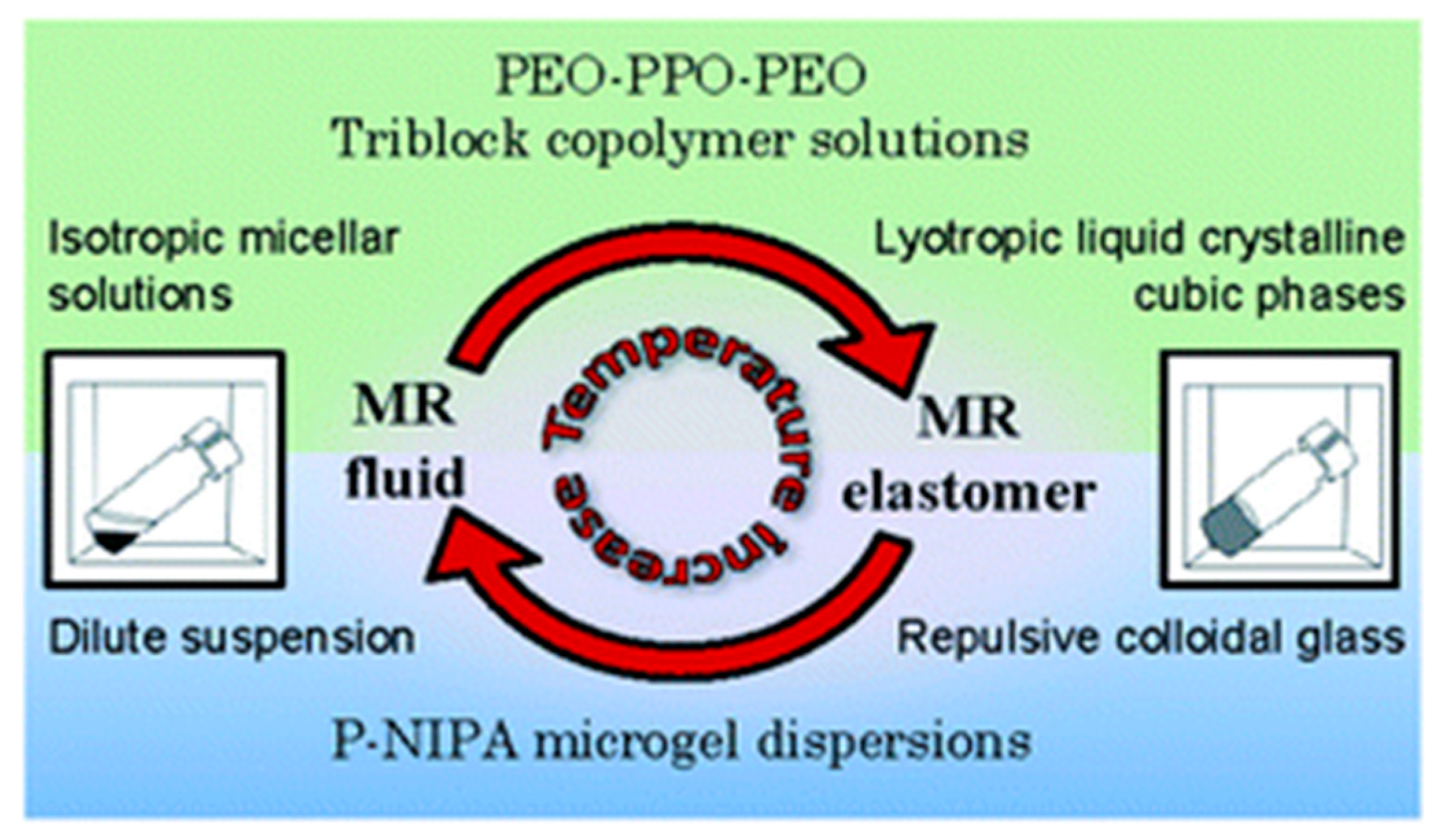
  4. Shahrivar, K.; de Vicente, J. Thermoresponsive polymer-based magneto-rheological (MR) composites as a bridge between MR fluids and MR elastomers. Soft Matter 2013, 48, 11451–11456. [Google Scholar] [CrossRef]
  5. Kim, Y.K.; Koo, J.H.; Kim, K.S.; Kim, S. Developing a real time controlled adaptive MRE-based tunable vibration absorber system for a linear cryogenic cooler. In Proceedings of the IEEE/ASME International Conference on Advanced Intelligent Mechatronics (AIM), Budapest, Hungary, 3–7 July 2011; pp. 287–290. [Google Scholar] [CrossRef]
  6. Ginder, J.M.; Scholotter, W.F.; Nichols, M.E. Magnetorheological elastomers in tunable vibration absorbers. In Proceedings of the SPIE’s 8th Annual International Symposium on Smart Structures and Materials, Newport Beach, CA, USA, 4–8 March 2001; Volume 4331. [Google Scholar] [CrossRef]
  7. Jolly, M.R.; Carlson, J.D.; Munoz, B.C. A model of the behaviour of magnetorheological materials. Smart Mater. Struct. 1996, 5, 607–614. [Google Scholar] [CrossRef]
  8. Balasoiu, M.; Bica, I. Composite magnetorheological elastomers as dielectrics for plane capacitors: Effects of magnetic field intensity. Results Phys. 2016, 6, 199–202. [Google Scholar] [CrossRef] [Green Version]
  9. Flatau, A.B.; Dapino, M.J.; Calkins, F.T. High bandwidth tenability in a smart vibration absorber. J. Intell. Mater. Syst. Struct. 2000, 11, 923–929. [Google Scholar] [CrossRef]
  10. Thevenot, J.; de Oliveira, H.; Sandre, O.; Lecommandoux, S. Magnetic responsive polymer composite materials. Chem. Soc. Rev. 2013, 42, 7099–7116. [Google Scholar] [CrossRef] [Green Version]
  11. Chertovich, A.V.; Stepanov, G.V.; Kramarenko, E.Y.; Khokhlov, A.R. New Composite Elastomers with Giant Magnetic Response. Macromol. Mater. Eng. 2010, 295, 336–341. [Google Scholar] [CrossRef]
  12. Krautz, M.; Werner, D.; Schrödner, M.; Funk, A.; Jantz, A.; Popp, J.; Eckert, J.; Waske, A. Hysteretic behavior of soft magnetic elastomer composites. J. Magn. Magn. Mater. 2017, 426, 60–63. [Google Scholar] [CrossRef]
  13. Filipcsei, G.; Csetneki, I.; Szilágyi, A.; Zrínyi, M. Magnetic Field-Responsive Smart Polymer Composites. In Oligomers-Polymer Composites-Molecular Imprinting; Springer: Berlin/Heidelberg, Germany, 2007; Volume 206. [Google Scholar] [CrossRef]
  14. Farshad, M.; Benine, A. Magnetoactive elastomer composites. Polym. Test. 2004, 23, 347–353. [Google Scholar] [CrossRef]
  15. Mehnert, M.; Hossain, M.; Steinmann, P. Towards a thermo-magneto-mechanical framework for magneto-rheological elastomers. Int. J. Solids Struct. 2017, 128, 117–132. [Google Scholar] [CrossRef]
  16. de Vicente, J.; Klingenberg, D.J.; Hidalgo-Alvarez, R. Magnetorheological fluids: A review. Soft Matter 2011, 8, 3701–3710. [Google Scholar] [CrossRef]
  17. Chen, L.; Jerrams, S. A rheological model of the dynamic behaviour of magnetorheological elastomers. Aip J. Appl. Phys. 2011, 110, 013513. [Google Scholar] [CrossRef]
  18. Samal, S.; Kolinova, M.; Blanco, I. The Magneto-Mechanical Behavior of Active Components in Iron-Elastomer Composite. J. Compos. Sci. 2018, 2, 54. [Google Scholar] [CrossRef] [Green Version]
  19. Kallio, M. The Elastic and Damping Properties of Magnetorheological Elastomers: Dissertation; VTT Technical Research Centre of Finland; VTT: Espoo, Finland, 2005; p. 146. Available online: http://www.vtt.fi/inf/pdf/publications/2005/P565.pdf (accessed on 27 June 2020).
  20. Samal, S.; Vlach, J.; Kavan, P. Improved mechanical properties of magneto rheological elastomeric composite with isotropic iron filler distribution. Ciência Tecnol. Dos Mater. 2016, 28, 155–161. [Google Scholar] [CrossRef]
  21. Samal, S.; Vlach, J.; Kolinova, M.; Kavan, P. Micro-computed tomography characterization of isotropic filler distribution in magnetorheological elastomeric composites. Adv. Process. Manuf. Technol. Nanostructured Multifunct. Mater. 2017, 7, 57–69. [Google Scholar] [CrossRef]
  22. Samal, S.; Kolinova, M.; Rahier, H.; Dal Poggetto, G.; Blanco, I. Investigation of the Internal Structure of Fiber Reinforced Geopolymer Composite under Mechanical Impact: A Micro Computed Tomography (µCT) Study. Appl. Sci. 2019, 9, 516. [Google Scholar] [CrossRef] [Green Version]
  23. Samal, S.; Škodová, M.; Blanco, I. Effects of Filler Distribution on Magnetorheological Silicon-Based Composites. Materials 2019, 12, 3017. [Google Scholar] [CrossRef] [PubMed] [Green Version]
  24. Dargahi, A.; Sedaghati, R.; Rakheja, S. On the properties of magnetorheological elastomers in shear mode: Design, fabrication and characterization. Compos. Part B Eng. 2019, 159, 269–283. [Google Scholar] [CrossRef]
  25. Asadi Khanouki, M.; Sedaghati, R.; Hemmatian, M. Multidisciplinary Design Optimization of a Novel Sandwich Beam-Based Adaptive Tuned Vibration Absorber Featuring Magnetorheological Elastomer. Materials 2020, 13, 2261. [Google Scholar] [CrossRef] [PubMed]
  26. Liu, C.; Jing, X.; Daley, S.; Li, F. Recent advances in micro-vibration isolation. Mech. Syst. Signal Process. 2015, 56–57, 55–80. [Google Scholar] [CrossRef]
  27. Kallio, M.; Lindroos, T.; Aalto, S.; Järvinen, E.; Kärnä, T.; Meinander, T. Dynamic compression testing of a tunable spring element consisting of a magnetorheological elastomer. Smart Mater. Struct. 2007, 16, 506–514. [Google Scholar] [CrossRef]
  28. Dong, X.-M.; Yu, M.; Liao, C.-R.; Chen, W.-M. A new variable stiffness absorber based on magneto-rheological elastomer. Trans. Nonferrous Met. Soc. China 2009, 19, s611–s615. [Google Scholar] [CrossRef]
  29. Samal, S.; Kolinova, M.; Blanco, I.; Dal Poggetto, G.; Catauro, M. Magnetorheological Elastomer Composites: The Influence of Iron Particle Distribution on the Surface Morphology. Macromol. Symp. 2020, 389, 1900053. [Google Scholar] [CrossRef]
  30. Seo, J.; Kim, S.; Samal, S.; Kim, H. Viscous behaviour of Bi2O3–B2O3–ZnO glass composites with ceramic fillers. Adv. Appl. Ceram. 2014, 113, 334–340. [Google Scholar] [CrossRef]
  31. Fu, S.-Y.; Feng, X.-Q.; Lauke, B.; Mai, Y.-W. Effects of particle size, particle/matrix interface adhesion and particle loading on mechanical properties of particulate–polymer composites. Compos. Part B 2008, 39, 933–961. [Google Scholar] [CrossRef]
  32. Nurul, A.Y.; Saiful, A.M.; Ubaidillah, S.A.; Salihah, T.S.; Nurul, A.A.W. Thermal Stability and Rheological Properties of Epoxidized Natural Rubber-Based Magnetorheological Elastomer. Int. J. Mol. Sci. 2019, 20, 746. [Google Scholar] [CrossRef] [Green Version]
  33. Samal, S.; Stuchlík, M.; Petrikova, I. Thermal behavior of flax and jute reinforced in matrix acrylic composite. J. Therm. Anal. Calorim. 2018, 131, 1035–1040. [Google Scholar] [CrossRef]
  34. Cantournet, S.; Desmorat, R.; Besson, J. Mullins effect and cyclic stress softening of filler elastomers by internal sliding and friction thermodynamics model. Int. J. Solids Struct. 2009, 46, 2255–2264. [Google Scholar] [CrossRef]
  35. Clough, J.; Creton, C.; Craig, S.; Sijbesma, R. Covalent bond scission in the Mullins effect of a filler elastomer: Real-time Visualization with Mechanoluminescence. Adv. Funct. Mater. 2016, 26, 9063–9074. [Google Scholar] [CrossRef] [Green Version]
  36. Chazeau, L.; Brown, J.D.; Yanyo, L.C.; Sternstein, S.S. Modulus recovery kinetics and other insights into the Payne effect for filled elastomers. Polym. Compos. 2000, 21, 202–223. [Google Scholar] [CrossRef]
  37. Frohlich, J.; Niedermeier, W.; Luginsland, H.-D. The effect of filler-filler and filler-elastomer interaction on rubber reinforcement. Compos. Part A Appl. Sci. Manuf. 2005, 36, 449–460. [Google Scholar] [CrossRef]
  38. Jolly, M.R.; Carlson, J.D.; Munoz, B.C.; Bullions, T.A. The magnetoviscoelastic effect of elastomer composites consisting of ferrous particles embedded in a polymer matrix. J. Intell. Mater. Syst. Struct. 1996, 7, 613–622. [Google Scholar] [CrossRef]
  39. Stepanov, G.V.; Borin, D.Y.; Raikher, L.Y.; Melenev, P.V.; Perov, N.S. Motion of ferroparticles inside the polymeric matrix in magnetoactive elastomers. J. Phys. Condens. Matter. 2008, 20, 204121. [Google Scholar] [CrossRef]
  40. Glavan, G.; Kettl, W.; Brunhuber, A.; Shamonin, M.; Drevenšek-Olenik, I. Effect of material composition on tunable surface roughness of magnetoactive elastomers. Polymers 2019, 11, 594. [Google Scholar] [CrossRef] [Green Version]
  41. Li, W.H.; Zhang, X.Z.; Du, H. Magnetorheological elastomers and their applications. In Advances in Elastomers I: Blends and Interpenetrating Networks; Visakh, P.M., Thomas, S., Chandra, A.K., Mathew, A.P., Eds.; Springer: Berlin, Germany, 2013; pp. 357–374. [Google Scholar]
  42. Boczkowska, A.; Awietjan, S. Microstructure and Properties of Magnetorheological Elastomers. Adv. Elastomers–Technol. Prop. Appl. 2012, 595. [Google Scholar] [CrossRef] [Green Version]
Figure 1. Magneto-rheological (MR) fluid to magneto-rheological elastomer (MRE) transition as a function of temperature. Reprinted from [3], © 2005 with permission from RSC.
Applsci 10 04899 g001
Figure 2. Schematic representation the describing the mechanism for the magnetization: (a) demagnetized stage, (b) low strain region—domain wall motion stage, (c) rotation (closest to the applied field) stage, and (d) saturation (alignment with applied field) stage.
Applsci 10 04899 g002
Figure 3. Chemical composition of elastomer matrix ZA 22 (a) and N1522 (b), poly addition and condensation, respectively.
Applsci 10 04899 g003
Figure 4. Fabrication of MRE composite with matrix and iron particles with presence of magnetic field. Reprinted from [19], © 2016 with permission from Elsevier.
Applsci 10 04899 g004
Figure 5. A static model of operation in squeeze form of deformation of MRE during compression with the magnetic domain. Reprinted from [19] © 2005 and [20], 2016 with permission from Elsevier.
Applsci 10 04899 g005
Figure 6. Static valve mode of operation using MRE on the top of the magnet and applying the loading force. Reprinted from [20], © 2016 with permission from Elsevier.
Applsci 10 04899 g006
Figure 7. Distribution of magnetic induction on the above configuration of MRE in presence of magnetic field (a) with mesh and considering surrounding atmosphere; (b) without mesh and using lines of force as external parameter. Reprinted from [18], © 2018 with permission from MDPI.
Applsci 10 04899 g007
Figure 8. Three electromagnet designs considered for the proposed adaptive tuned vibration absorber (ATVA). (a) H-shaped electromagnet; (b) C-shaped electromagnet; and (c) U-shaped electromagnet. Reprinted from [25], © 2020 with permission from MDPI.
Applsci 10 04899 g008
Figure 9. (a) The schematic structure of the magneto-rheological fluid embedded pneumatic vibration isolator (MrEPI) and (b) its equivalent mechanical system. Reprinted from [26], © 2015 with permission from Elsevier.
Applsci 10 04899 g009
Figure 10. Schematic configuration (a) and photograph (b) of the MRE absorber. Reprinted from [28], © 2009 with permission from Elsevier.
Applsci 10 04899 g010
Figure 11. Filler, Elastomer, and MREs composite SEM images: (a) iron fillers, (b) particle size distribution in N1522 MRE composite, (c) Elastomer ZA22, (d) Elastomer N1522, (e) ZA22 Elastomer Composite, (f) N1522 Elastomer Composite, (g) Micro fibrils of ZA22 MRE composite, and (h) Micro fibrils for N1522 MRE composite. Reprinted from [18], © 2018 with permission from MDPI and from [21], © 2017 with permission from Wiley.
Applsci 10 04899 g011
Figure 12. Anisotropic distribution filler within the elastomer composite in transverse (a) and longitudinal (b) direction from POM (polarizing optical microscope). Reprinted from [18], © 2018 with permission from MDPI.
Applsci 10 04899 g012
Figure 13. 2D frame of the filler distribution in MRE composite in Z (a), X (b), Y (c) direction. Reprinted from [18], © 2018 with permission from MDPI.
Applsci 10 04899 g013
Figure 14. µCT surface features of MREs composite in 3D planes: (a) µCT of ZA22 MRE sample, (b) inner position of ZA22 MRE sample, (c) µCT of N1522 MRE sample, and (d) inner position of N1522 MRE sample. Reprinted from [18], © 2018 with permission from MDPI.
Applsci 10 04899 g014
Figure 15. Force versus position for the MRE sample under static with single valve and deformation mode under various magnetic flux intensity (T). (a) Force versus displacement for compression; (b) relaxation stage at various magnetic intensity. Reprinted from [20], © 2016 with permission from Elsevier.
Applsci 10 04899 g015
Figure 16. Single (a) and double (b) lap shear test scheme.
Applsci 10 04899 g016
Figure 17. Effect of magnetic flux density on the measured stress-strain hysteresis loops of the MRE as a function of different strain amplitude at 10Hz: (a) 2.5%; (b) 5%; (c) 10%; and (d) 20%. Reprinted from [24], © 2019 with permission from Elsevier.
Applsci 10 04899 g017

