Article

Removable Weighing Lysimeter for Use in Horticultural Crops

by
Juan Antonio Nicolás-Cuevas
1,
Dolores Parras-Burgos
2,*,
Manuel Soler-Méndez
1,
Antonio Ruiz-Canales
3 and
José Miguel Molina-Martínez
1
1
Research Group in Agromotic Engineering and the Sea, Universidad Politécnica de Cartagena, 30202 Cartagena, Spain
2
Department of Structures, Construction and Graphic Expression, Universidad Politécnica de Cartagena, 30202 Cartagena, Spain
3
Engineering Department, Universidad Miguel Hernandez, 03312 Orihuela, Alicante, Spain
*
Author to whom correspondence should be addressed.
Appl. Sci. 2020, 10(14), 4865; https://doi.org/10.3390/app10144865
Submission received: 2 June 2020 / Revised: 5 July 2020 / Accepted: 14 July 2020 / Published: 15 July 2020

Abstract

:

Featured Application

Small weighing lysimeter for horticultural crops whose root depth is up to 300 mm providing an easy installation and removal, good structural performance and reliable water balances results.

Abstract

Water resources management is a priority issue in agriculture, especially in areas with water supply problems. Recently, one of the most widespread technologies for measuring crop water requirements are weighing lysimeters. Nevertheless, this type of lysimeters are of large dimensions and require a civil work for their installation. In this article, we present a weighing lysimeter prototype (1000 × 600 mm and 350 mm depth) designed to be used in agricultural farming of horticultural crops. We described the design details that includes ease of assembly, carriage and minimum soil alteration. Structural design results and construction process are also provided showing their performance under different tractors scenarios. The measurements accuracy results show the outcomes of the prototype after being tested. Finally, we discuss our design and measurements results by comparing them with other weighing lysimeters. In comparison, the prototype designed is an accurate and reliable device which reduces the surface and depth of the current weighing lysimeters.

1. Introduction

The efficient management of water resources allows improving the productivity, stability and quality of crops, achieving a rational use of water and energy [1,2,3]. This is especially important in areas with problems of water scarcity, like in semiarid regions of the southeast of Spain where water shortage and rising water costs compromise farms’ viability [4]. Moreover, the reduction in the use of water decreases the pollution of the environment [5,6].
For an efficient use of water, crop evapotranspiration (ETC) is a fundamental data in order to adapt the amount and frequency of irrigation to the demands of each crop [6,7]. Because of direct determination of plant water needs is complicated, indirect methods have been established based in weather variables and agronomic information. In this way, the FAO Penman–Monteith methodology (FAO, Food and Agriculture Organization of the United Nations) [8] has been profusely used. According to it, the estimation of ETc is calculated multiplying the product of the reference crop evapotranspiration (ETO) by a crop coefficient (Kc). However, accurate estimation of evapotranspiration is a complex task that requires measurement of numerous physical, meteorological and vegetation cover parameters. Moreover, other methods for estimating ETc have been developed in recent years, such as the use of image analysis to measure effective diameter in lettuce crops [1,2,9], which require a personalized calibration process according to the type of crop [10].
Conversely, it is considered that methods directly measuring crop water balance, such as the weighing lysimeter provide the most precise values to estimate the ETc [6,11,12,13,14,15]. To achieve that, a properly calibration of the lysimeters and a representative surrounding field in situ provide small measurements errors. The accuracy of water measured depends on the representativeness of the lysimeter in comparison to the field, the similarity of the plants inside and outside of the lysimeter and the influence of edge effects, boundary conditions, soil properties, fetch and lysimeter surface area [16]. Recently, the development of the load cells and datalogger technology allows one to obtain high-precision weighing lysimeters [17,18]. These lysimeters can be used to determine evapotranspiration with measurement reliability [19], and an accuracy of hundredths of millimeters reducing investment and maintenance costs and making commercial use possible [20,21,22].
There are two types of lysimeters, weighing and volumetric. The volumetric type estimates the ETC as a residual by measuring all other components of the soil water balance [23]. In weighing lysimeters, the increase or loss of water is measured by the change in mass obtained by weighing the container in which the soil is located. Lysimeters are usually considered difficult to handle, costly to build and their use and maintenance require special care, so their use is usually restricted to research centers [24,25]. Different weighing lysimeters have already been reported in the literature [26,27,28,29,30,31].
To avoid the inconveniences there are some little lysimeters like the proposed by Misra et al. [32], of 20 kg of capacity of low cost, but it has a low resolution in ET and it was used in glasshouse. The lysimeter applied in greenhouse to sugarcane pre-sprouted plantlets of Libardi et al. [33], and the triangular weighing lysimeter for potted plants of Ruíz-Peñalver et al. [14], implemented in a lysimetric station. However, these weighing lysimeters are not intended for their use on intensive farms but on research studies. In recent years, small cylindrical weighing lysimeters are being commercialised such as the Smart Field Lysimeter (SFL) and the Ready-To-Go lysimeter. Evapotranspiration studies have been carried out with SFL [34,35]. Using an SFL of 30 cm diameter and 30 cm depth, Doležal et al. [34] provided accurate evapotranspiration data for the days without precipitation of an unirrigated grass commonly used on weather stations. Rafi et al. [35] studied wheat crop evapotranspiration partitioning with two SFLs of 30 cm diameter and different depths, one of 300 mm and other of 900 mm. The evapotranspiration estimated by the lysimeters were quite consistent with other methods, except in very wet or dry conditions. When it happened, the lysimeters slightly overestimated or underestimated the values.
Using tractors with agricultural machinery in the area around the lysimeters reduces hand labour and is usual in commercial farms. These tractors introduce new loads that must be supported by the lysimeters. These loads can be particularly important in small lysimeters as their lightweight structure might suffer deformations that affect the weighing system. Hagenau et al. [36] studied the influence of a footpath in two weighing lysimeters showing different evapotranspiration results during harvest period. The data illustrated that the exposure effect can modify the water balance. However, no studies have been carried out to analyse the possible effect of the machinery. It is probably due to the fact that their use is often restricted to research centres and not in agricultural farming.
The design provided in this article allows farmers to incorporate them into their crops for an optimal water resource management using available technologies. Among the required lysimeter characteristics to achieve farmer needs, the following ones stand out: (i) small dimensions in order to be installed and integrated in the field within the plantation framework; (ii) easy to be transported and located, at the end of a crop cultivation season, to another production area, (iii) an affordable cost for a rapid amortization and (iv) good performance under tractor operations. One of the main difficulties in carrying out the development of the prototype, known as LP1, consists of designing equipment of reduced dimensions and weight for its transport, which incorporates a container for the crop that can withstand the stresses caused by the soil, the loads of which are supported by a weighing system, without being affected by the surrounding soil.
This article shows the design of the prototype carried out to meet the previously established needs, its development, installation and field evaluation. It provides a high-precision quantification of evapotranspiration by weight change over short intervals of time and, therefore, an improvement of water management in intensive farms.

2. Materials and Methods

The proposed weighing lysimeter was designed as a device composed of several components: (i) a cultivation tank to hold a volume of reconstituted soil from the plot to reproduce the natural conditions and to determine the evapotranspiration of the crop during its growth, (ii) a tank to collect and measure the water drained through the confined soil and (iii) a weighing system to determine water variations of the soil mass and the drainage tank.
The following sections describe in more detail the design of this small removable weighing lysimeter model, the structural analyses carried out on its main parts and the installation process.

2.1. Design Process of the Weighing Lysimeter

2.1.1. Crop Type Selection

The dimensions were determined to accommodate six lettuce plants arranged in staggered order, with a separation between plants of 330 mm and between rows of approximately 191 mm, as they would commonly be in the field as suggested by Casseres [37] (Figure 1). This crop was particularly chosen for two main reasons: its higher planting density higher due to its canopy size and its similar root depth in comparison to other small horticultural crops.

2.1.2. Weighing Lysimeter Design

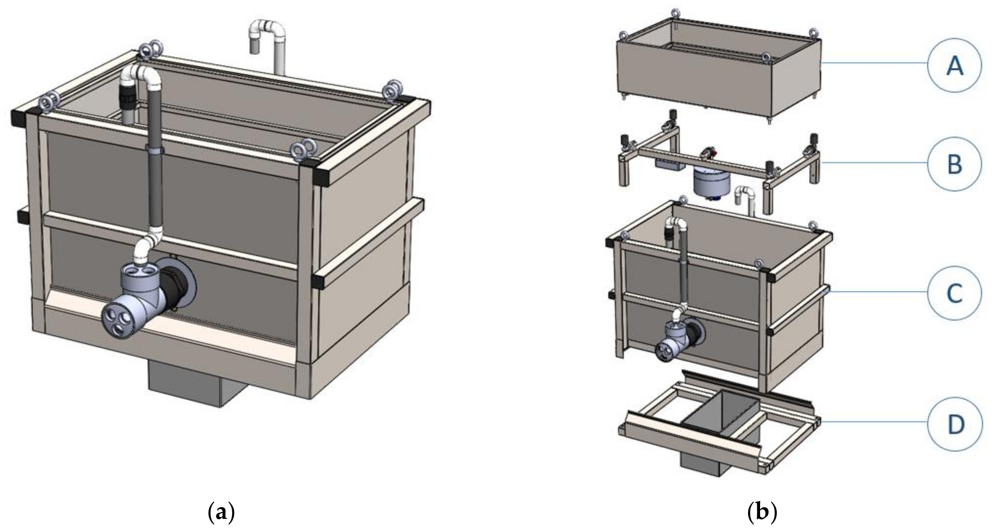
The main structure of the weighing lysimeter consisted of a set of elements that ensured the containment of the soil, separating it from the cultivation tank, which was laid on a weighing system (Figure 2). All the lysimeter elements were made of stainless steel AISI 304. To improve the carriage and assembly conditions, the internal structure was placed independently; this reduced the weight during assembly and facilitated maintenance.
Inside the main structure, the cultivation tank was placed on an internal support structure, which transmitted the loads to the foundation base structure and where the five load cells (UTILCELL, S.A., Barcelona, Spain) were located (Figure 2b (B)): four for the cultivation tank and one for the drainage tank. The bottom of the cultivation tank had a truncated pyramid shape to facilitate drainage and avoid water accumulation on the bottom (Figure 2b (A)). At the bottom, there was an orifice connected to an electrovalve that regulated water outlet.
The drainage tank was located under cultivation tank and was a cylindrical stainless-steel tank with a curved bottom to facilitate water evacuation. Its function was to collect the drainage water of the cultivation tank for later measurement. It was attached to a load cell using a threaded rod from the centre of the tank lid to the end of the load cell. This tank was equipped with a funnel that is located under the end of the electrovalve from the cultivation tank. The funnel carried the drained water into the tank preventing any contact with other elements of the cultivation tank. The load cells were installed according to the manufacturer’s specifications on a smooth supporting surface.
The amount of water that entered at bottom of the entire weighing lysimeter was extracted by means of a submersible suction pump, which was connected to a flexible rubber tube that conducted the drained water to the exterior and poured it at a distance of at least 4 m from the lysimeter. Thus, water did not interfere with the growth of plants in the vicinity of the lysimeter.

2.2. Structural Analysis

To assure a proper performance of the lysimeter, the cultivation tank and the main structure were separated by a gap. This prevented that their elements deformations interfered with each other and modified the measurements of the weighing system.
The SolidWorks 2016 software (Dassault Systèmes, S.A., Vélizy-Villacoublay, France) was used to design all the components of the lysimeter and its structural behaviour was studied using SolidWorks Simulation. A static analysis was performed to simulate the stresses and deformations that occur in the walls of the cultivation tank, the main structure, and the base structure under different load conditions.
The prototype was installed in semi-hard clay soil. This type of soil tends to swell or contract when the moisture content varies. The characteristics of this soil were taken from the Technical Building Code [38] with a bulk-density of 19,000 N/m3, an internal friction angle 18° (φ), an active earth pressure coefficient (Ka) of 0.528 and a ballast coefficient of 45 × 106 N/m2 (K30).
The estimated active lateral earth pressures, which are produced by the live load that may be presented on the lysimeter structure (uniform distribution), were based on the Rankine’s theory (Equation (1)):
Ea = Ka × q
where Ka is the active earth pressure coefficient (Equation (2)) and q is the load that may be present.
Ka = (1 − sinφ)/(1 + sinφ)
For the variable q, a triangular distribution was assumed for lateral earth pressure due to backfill and a uniform distribution in the case of live loads such as tractors and agricultural machinery. Three live load values were estimated that could be presented in the field, related to the average weight of tractors and their contact area (Table 1). The live load values were 5000 N/m2 (A), 10,000 N/m2 (B) and 15,000 N/m2 (C), respectively, for the light, medium and heavy scenarios of tractors with agricultural machinery. These values were estimated dividing tractors and machinery weight (30,000, 50,000 and 85,000 N) by the surface provided by the wheelbase and the vehicle width (2.4 m2).
From Equations (1) and (2), the maximum value of the lateral earth pressure (triangularly distributed) due to backfill is 10,000 N/m2 and live load values A, B and C (uniformly distributed) were 2640, 5280 and 7920 N/m2. The simple and the combined loading cases are shown in Table 1.
For the analysis of the three-dimensional models carried out with SolidWorks Simulation, it was necessary to simplify the original models, which allowed optimizing the mesh size and computational resources [39]. To make the finite element model of the cultivation tank and the main structure, “BEAM” type elements for the tubular profiles and “SHELL” type elements for the sheets due to its low thickness were used.
To model the finite elements of the base structure, “SOLID” type elements were used for the tubular profiles and the sheets. The floor was a compressible material that was deformed by the loads transmitted by the foundation. It was considered that the ground under the foundation was constituted by a semi-hard clay, with a ballast coefficient K30 = 45 × 106 N/m2. This value is defined in table D29, annex E from Technical Building Code, DB SE- C [40].
The soil stiffness was simulated using elastic supports, a common structural support approximation in these cases. This assumption implies that an opposing pressure on the contact surface was directly proportional to the displacement normal component (Finite Element Analysis Concepts: Via Solidworks [41]).

2.3. Acquisition and Control System

The weighing system consisted of five load cells, UTILCELL model 300, in accordance with the OIML R60 class C regulations. Four of the load cells used for the cultivation tank had a sensitivity of 2 mV/V and a nominal capacity of 150 kg. The load cell used for the drainage tank had same sensitivity that the other four load cells, but its nominal capacity was of 10 kg. The maximum load for each group of load cells was 300 kg and 20 kg, and its weighing accuracy was of 15 g and 1 g respectively.
The data obtained from the load cells were recorded a model CR3000 datalogger (Campbell Scientific Spain, S.L., Barcelona, Spain). It had an analogue-digital convertor of 16-bit, 14 differential analogue inputs, four voltage excitation terminals and eight I/O ports. The control module was in charge of controlling the solenoid valves, closing or opening the solenoid valves. The accumulated water was drained for weight and subsequent evacuation with a model SWIFT weighing indicator (UTILCELL, S.A., Barcelona, Spain) and analogue-digital convertor of 24 bits. The system for controlling the solenoid valves was powered by a 24 V current circuit. The transmission system was carried out by means of a Wi-Fi network system connected to the cloud.

2.4. Validation

The field experiment was carried out in the experimental lysimeter station “Las Tiesas” (Albacete, Spain) supported by the “Instituto Técnico Agronómico Provincial” (ITAP) during 2017. It was located in Albacete, Spain, longitude 39°14′ N, latitude 2°5′ W and altitude 695 m above sea level. It has a semi-arid climate. The mean annual maximum and minimum daily air temperatures for 2011 were 20.9 and 7 °C, respectively, and the annual average precipitation 1 l/m2. The soil texture of the plot is loamy, with a field capacity of 0.28 (g cm−3) and a wilting point of 0.10 (g cm−3). The irrigation water used was of medium quality, with a light-moderate electrical conductivity and a moderate content of total salts. Additional information is available elsewhere [6]. The facility had a localised irrigation system with a programmer that supplied irrigation to the crop during the entire trial. The romaine lettuce crop (Lactuca Sativa L. cv. Neruda) was utilised to determinate the dimensions of the cultivation tank of weighing lysimeter, however the barley crop was chosen to validate the LP1 prototype.
A weighing lysimeter of the ITAP was used to validate the LP1 prototype. The ITAP lysimeter was cultivated with the same crop and following the same procedures as LP1 prototype. The dimensions of the ITAP weighing lysimeter recipient were 2.3 m × 2.7 m and 1.7 m depth, with approximately 14.5 t total mass. The soil was cultivated previously with sunflower that was harvested and the residues removed before the beginning of the experiment. The lysimeter recipient was surrounded by a square protection plot to avoid runoff and was located in the centre of the cultivated hectare. ETc was daily calculated using the registered weight, corrected by drainage. Daily weather and soil parameters were measured at the site. Prototype LP1 calculations were done every minute or hourly.
Crop evapotranspiration was obtained by two methods. Following the methodology proposed by Allen et al. [24] a water balance was carried out. The first method was a subtraction of the accumulation of inputs (rainfall and irrigation) and of the accumulation of outputs (ETc and drainage). Both inputs and outputs were quantified as the sum of minute or hourly weight variations throughout the crop cycle. The second method was the difference of the initial and final weights recorded by the lysimeter.

3. Results

3.1. Structural Analysis

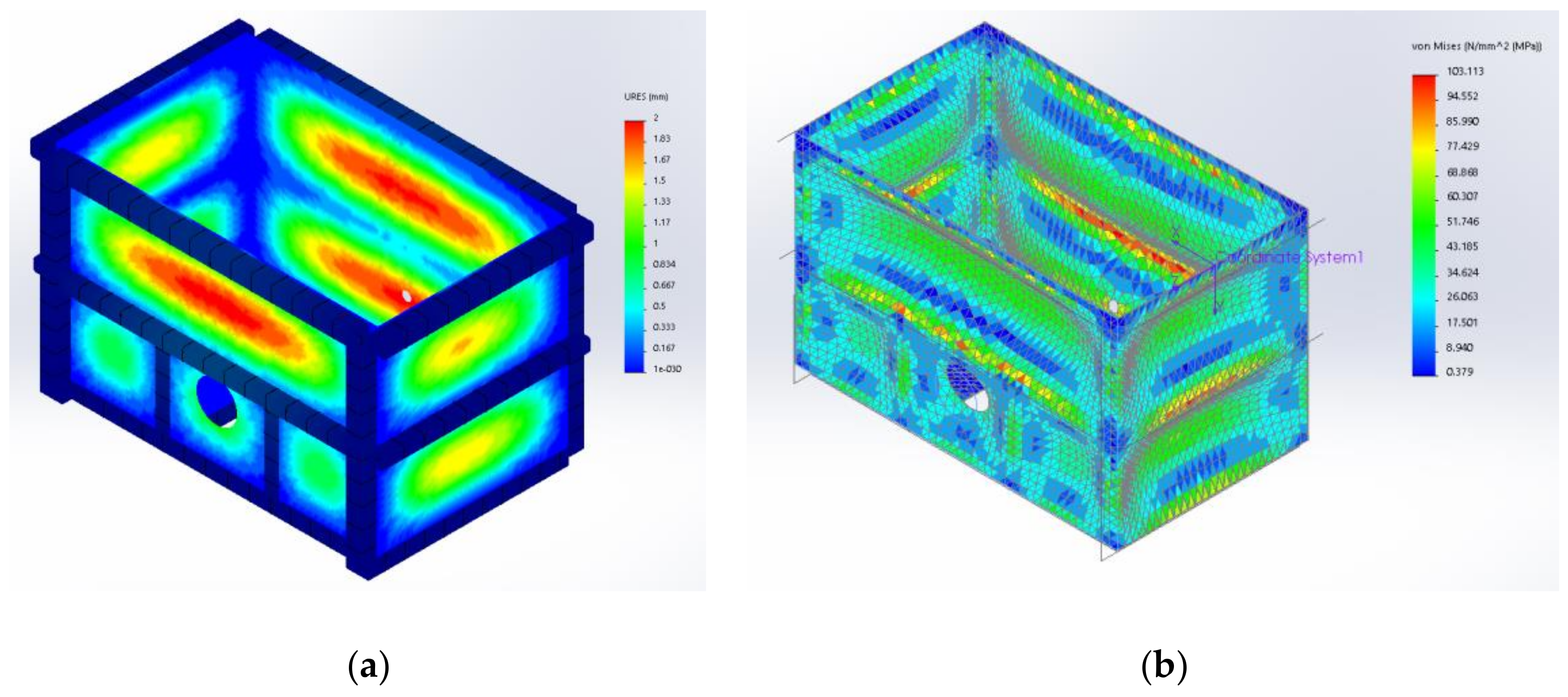
Static analysis indicated that the maximum deformations experienced by each of the structures did not exceed the separation between them for the different load situations considered (Table 2). For the cultivation tank, the greatest deformation was 0.147 mm and the Von Mises equivalent stress was 12.982 MPa (Table 2, Figure 3). For the main structure, the sheet deformation for load combinations 2, 3 and 4 was more than half their thickness. For the main structure, the deformation and Von Mises equivalent stress were 2 mm and 113.85 MPa, respectively (Figure 4).
The largest vertical displacement was 0.955 mm and the Von Mises equivalent stress is 32.429 MPa (Table 2). The settlements at the ends were uniform and no differential settlements compromised the proper performance of the lysimeter weighing system (Figure 5a). Otherwise, the levelling system included in the main structure could have absorbed the differential soil settlements. For the type of soil and the different loads considered in this study, the lysimeter base showed small total deformations. In any case, the Von Mises equivalent stress of the designed base did not exceed the elastic limit of the AISI 304 steel (Figure 5b).

3.2. Construction

The lysimeter cultivation tank consisted of bent and welded stainless steel plates. Inside it, horizontal bars were arranged as parallel rings to increase the resistance and reduce the deformations of the plates. The internal dimensions of the cultivation tank were 1000 mm × 600 mm, with a depth at the ends of 300 mm and in the centre of 350 mm. The lysimeter dimensions were determined to align six lettuce plants in a 60-degree staggered pattern with a 330 mm plant spacing (Figure 1). An inverted truncated pyramid shape of the cultivation tank bottom facilitates the drainage and avoids water accumulation. The drained water outlet was automatically controlled by an electrovalve placed in an orifice at its deepest point.
A support structure was placed under the cultivation tank, which transmitted the loads to the foundation base structure. In the prototype, 40 × 40 mm and 2 mm thick profiles were welded together (Figure 2b (B)). The ends of the internal structure supports were fixed to L-shaped pieces and welded to the foundation base. This design reduces the weight during assembly and facilitates maintenance operations. Inside the main structure, the cultivation tank laid on an internal support structure where the five load cells are located: four for the cultivation tank and one for the water collector vessel drained by the cultivation tank. Under the cultivation tank was located the drainage system formed by a cylindrical stainless-steel tank with a curved bottom to facilitate water evacuation, whose function was to collect the drainage water for later measurement.
The load cells were installed according to the manufacturer’s specifications on a smooth supporting surface. The load cells were supported by a steel structure on which the stainless-steel cultivation tank is located. The load cells are screwed to steel cylinders of 30 mm diameter. The cylinders were welded to the support structure of the cultivation tank. To prevent the damage of load cells due to accidental overloads, a screw was installed under each of them. These screws provided end stops to the load cells movements.
The main structure was a buried container in contact with the ground, with free internal dimensions of 1030 × 630 × 660 mm (length × width × depth). The cultivation tank was placed inside with a 15 mm separation gap on each side (Figure 2b (C)). In order to improve the support capacity of the main structure with the ground, the structure was provided with a base as a shallow foundation. The loads were transmitted in a way that was acceptable to the ground (Figure 2b (D)). In addition, this base ensured a support surface with which the main structure could be levelled facing possible ground settlements. Heavy rains or the increase of the phreatic level could flood the main structure. To avoid that, the water was extracted by a submersible pump connected to a flexible rubber tube. This pump system was designed to conduct the drained water to the exterior and pour it off a minimum distance of 4 m from the lysimeter. This extracted water did not interfere with the growth of plants around the lysimeter.

3.3. Installation

The weighing lysimeter soil was reconstructed after it was built. The soil inside the cultivation tank was the same soil of the farm plot. The plot soil was tilled to a depth of approximately 30 cm and prepared before planting. The same soil was incorporated into the cultivation tank, including the applied bottom fertilizer and the dry matter, maintaining the same texture and structure. In order to improve the performance of the drainage system, a geotextile sheet, a 50 mm layer of gravel, and a second geotextile were placed in the deepest part of the cultivation tank. These layers served as a filter to prevent clogging the drainage system and allows the free movement of water to the drainage system. The next 300 cm are occupied by the reconstituted soil. The process described above is shown in Figure 6.

3.4. Operation Results

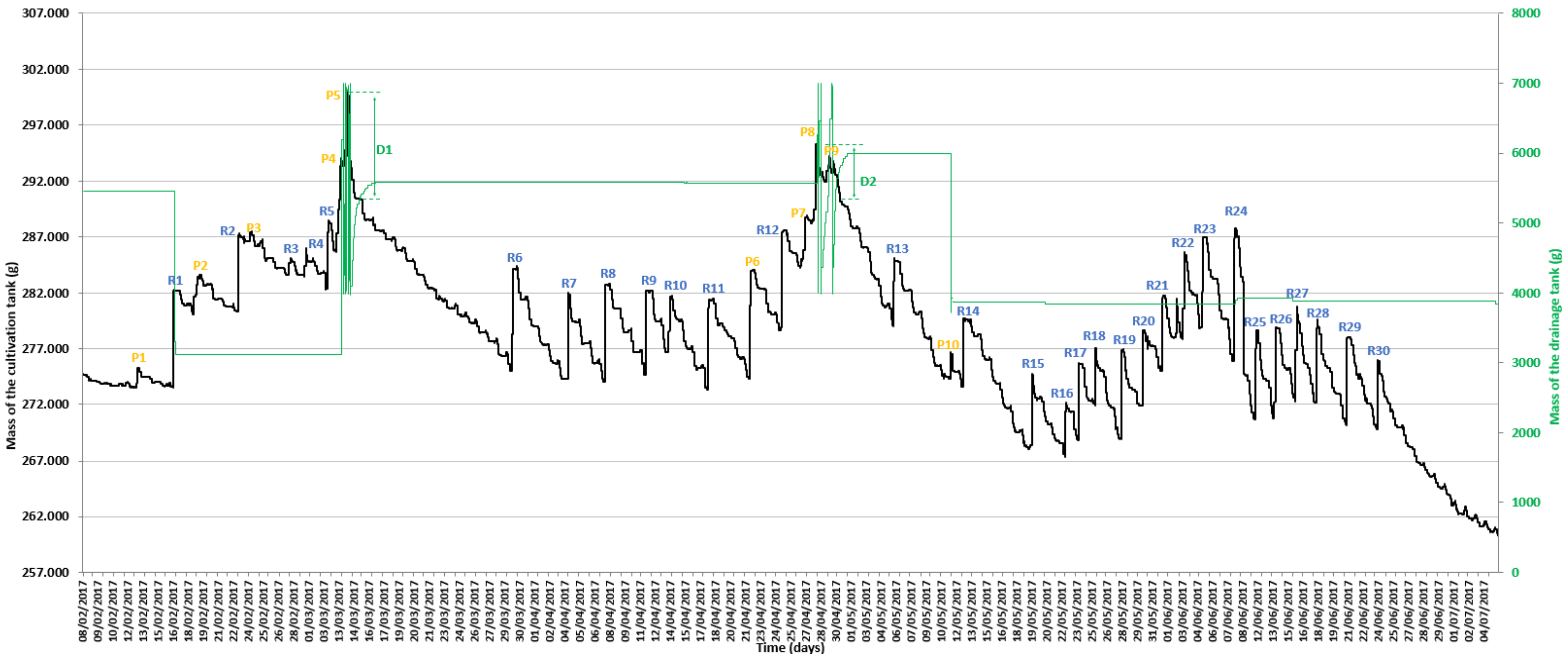
The results obtained in the water balance and weight difference are shown in Table 3 and Figure 7, respectively.
The weight variations aided to detect the variables involved in the irrigation process of the plant-soil system. This water balance showed accurate measurements of LP1 prototype water losses during a whole season as they were recovered precisely (Table 3).
The weight of the cultivation tank increased due to irrigation and rainfall, as well as it decreased as expected (Figure 7). Initially, the weight of the cultivation tank decreased rapidly due to the drainage of the water through the soil, followed by a slower decline because of crop water consumption. Some precipitation events increased the water content beyond field capacity. The drainage tank then reached its maximum weight and had a frequent cycle of recharge with subsequent water drains, which resulted into ups and downs of weight in the drainage tank (Figure 7). These weight oscillations were also observed in the cultivation tank as its weight slightly increased during the night due to the condensation and diminished throughout the day.

3.5. Validation of the Obtained Data

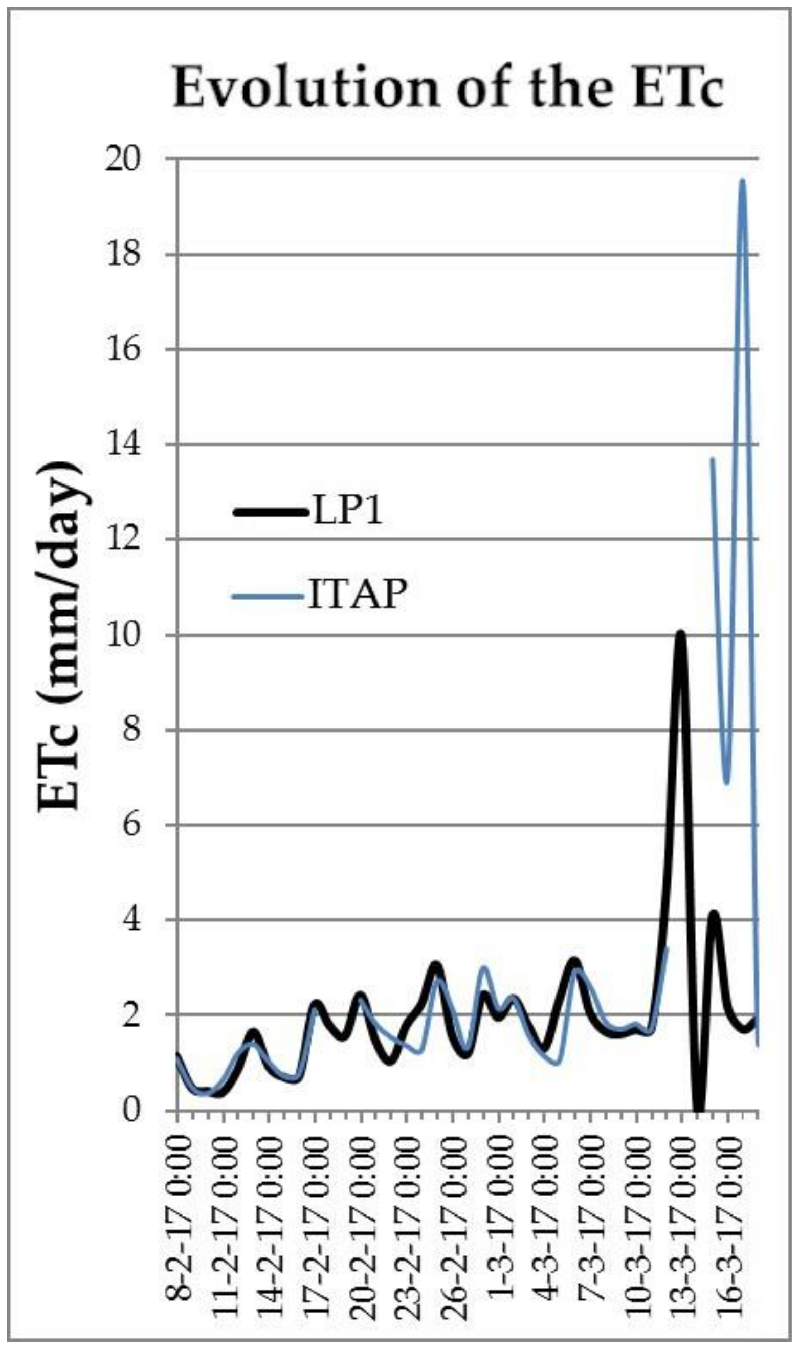
The obtained data by the LP1 and ITAP weighing lysimeter were compared during a barley cultivation season. The ITAP lysimeter had a precision of 250 g (equivalent to 0.04 mm of water). The surface area and depth effects in the drainage conditions of both lysimeters were different; therefore, only the ETc was contrasted (Figure 8). Data LP1 were changed to hourly data to be compared with ITAP lysimeter.
Heavy rains occurred during the period between March 13 and 17 that caused damages in ITAP weighing lysimeter providing no valid data (Figure 8). The ETc values at beginning of the experiment in the field were similar. There was a little difference because of plantation densities. During cultivation time a slight deviation of ETc values were registered, but with a similar pattern for both devices. Thus, an average standard deviation of 0.97 g between LP1 and ITAP values were obtained.

4. Discussion

The LP1 weighing lysimeter has been designed for horticultural crops, so that its dimensions (1000 × 600 mm and 350 mm depth) were adapted to the crop planting pattern, reducing as much as possible the surface and depth of the lysimeter without altering the root growth of the crop. This prototype allows the ease of components carriage and assembly.
Other small weighing lysimeters from the literature, such as the Smart Field Lysimeter and the Ready-To-Go lysimeter have a cylindrical shape. The Smart Field Lysimeter have models with 30 cm diameter and different depths of 30, 60 and 90 cm of the cultivation tank. The Ready-To-Go lysimeter have models with 30 or 80 cm diameter and different depths of 30, 60 and 90 cm of the cultivation tank. The lysimeters mentioned are cylindrical and their dimensions are not sufficiently adapted to horticultural crops.
LP1 weighing lysimeter is able to register with precision the increase and the decrease of the water content provided by the irrigation, precipitation, dew, ETc and drainage. ETc is reflected in the slow decrease of weight of the cultivation tank. The validation of LP1 with ITAP lysimeter shows a good performance during the experiment. Thus, it can be used to get very accurate parameters measurements for the irrigation management and to validate other lysimeters, ETc methods or crop development functions.
Considering the decrease of water content is related to the evolution of drained tank weight, the drainage water amount and field capacity of the soil can be determined. It is also possible to know other relevant parameters as infiltration rate using the weight variations between cultivation tank and drainage tank.
During the evaluated period the ITAP lysimeter was flooded because of heavy rains occurred from March 13 to March 17. Before this date, the ITAP lysimeter was working properly and the values were very similar. After the rains, the ITAP lysimeter did not function well providing erroneous data. In spite of the heavy rains our prototype continued working properly.

5. Conclusions

To conclude, the removable weighing lysimeter developed for use in horticultural crops facilitates its installation and removal with a minimum alteration of the land. In principle, the lysimeter was designed for lettuce crops but it can be used with other crops with a similar depth root. Its design also prevents some difficulties like load cells and datalogger maintenance. The structural response caused by different load cases, such as tractors, meet the requirements for proper operation. Finally, this weighing lysimeter of small dimensions is able to measure evapotranspiration with high accuracy and precision.

6. Patents

There is one patent resulting from the work reported in this manuscript: Real-time modular remote management system for the vegetative state of crops, water and nutrients consumption. Publication number: 2668210. National Application Number: 201830216.

Author Contributions

Conceptualization, J.A.N.-C. and D.P.-B.; Methodology, J.A.N.-C. and J.M.M.-M.; Software J.A.N.-C. and D.P.-B.; Validation, J.A.N.-C. and J.M.M.-M; Formal Analysis, M.S.-M.; Investigation, J.A.N.-C., D.P.B., M.S.-M., A.R.-C. and J.M.M.-M.; Resources, M.S.-M. and A.R.-C.; Writing—Original Draft Preparation, J.A.N.-C. and D.P.-B.; Writing—Review and Editing, Supervision, Project Administration, Funding Acquisition, A.R.-C. and J.M.M.-M. All authors have read and agreed to the published version of the manuscript.

Funding

This research has been supported by the Spanish Ministry of Economy and Competitiveness (MINECO) and the European Commission FEDER funds under the grant number AGL2015-66938-C2-1-R.

Acknowledgments

The authors would like to thank the technical support of TeleNatura EBT S.L for their assistance.

Conflicts of Interest

The authors declare no conflict of interest.

References

  1. González-Esquiva, J.; García-Mateos, G.; Escarabajal-Henarejos, D.; Hernández-Hernández, J.; Ruiz-Canales, A.; Molina-Martínez, J. A new model for water balance estimation on lettuce crops using effective diameter obtained with image analysis. Agric. Water Manag. 2017, 183, 116–122. [Google Scholar] [CrossRef]
  2. Hernández-Hernández, J.; Ruiz-Hernández, J.; García-Mateos, G.; González-Esquiva, J.; Ruiz-Canales, A.; Molina-Martínez, J. A new portable application for automatic segmentation of plants in agriculture. Agric. Water Manag. 2017, 183, 146–157. [Google Scholar] [CrossRef]
  3. Nie, Y.; Avraamidou, S.; Xiao, X.; Pistikopoulos, E.N.; Li, J.; Zeng, Y.; Song, F.; Yu, J.; Zhu, M. A food-energy-water nexus approach for land use optimization. Sci. Total Environ. 2019, 659, 7–19. [Google Scholar] [CrossRef] [PubMed] [Green Version]
  4. Jiménez-Buendía, M.; Ruiz-Peñalver, L.; Vera-Repullo, J.; Intrigliolo-Molina, D.; Molina-Martínez, J. Development and assessment of a network of water meters and rain gauges for determining the water balance. New scada monitoring software. Agric. Water Manag. 2015, 151, 93–102. [Google Scholar] [CrossRef]
  5. Liu, J.; Yang, H.; Gosling, S.N.; Kummu, M.; Flörke, M.; Pfister, S.; Hanasaki, N.; Wada, Y.; Zhang, X.; Zheng, C. Water scarcity assessments in the past, present, and future. Earth’s Future 2017, 5, 545–559. [Google Scholar] [CrossRef] [PubMed]
  6. López-Urrea, R.; de Santa Olalla, F.M.; Fabeiro, C.; Moratalla, A. Testing evapotranspiration equations using lysimeter observations in a semiarid climate. Agric. Water Manag. 2006, 85, 15–26. [Google Scholar] [CrossRef]
  7. Uniyal, B.; Dietrich, J.; Vu, N.Q.; Jha, M.K.; Arumí, J.L. Simulation of regional irrigation requirement with swat in different agro-climatic zones driven by observed climate and two reanalysis datasets. Sci. Total Environ. 2019, 649, 846–865. [Google Scholar] [CrossRef]
  8. Allen, R.G.; Pereira, L.S.; Raes, D.; Smith, M. Crop Evapotranspiration-Guidelines for Computing Crop Water Requirements-FAO Irrigation and Drainage Paper 56; FAO: Rome, Italy, 1998; Volume 300, p. D05109. [Google Scholar]
  9. Mateo-Aroca, A.; García-Mateos, G.; Ruiz-Canales, A.; Molina-García-Pardo, J.M.; Molina-Martínez, J.M. Remote image capture system to improve aerial supervision for precision irrigation in agriculture. Water 2019, 11, 255. [Google Scholar] [CrossRef] [Green Version]
  10. Escarabajal-Henarejos, D.; Molina-Martínez, J.; Fernández-Pacheco, D.; Cavas-Martínez, F.; García-Mateos, G. Digital photography applied to irrigation management of little gem lettuce. Agric. Water Manag. 2015, 151, 148–157. [Google Scholar] [CrossRef]
  11. Aboukhaled, A.; Alfaro, J.; Smith, M. Los Lisímetros. Estudios FAO, Serie Riego y Drenaje; FAO: Roma, Italy, 1986.
  12. Howell, T.A.; Schneider, A.D.; Jensen, M.E. History of Lysimeter Design and Use for Evapotranspiration Measurements; ASCE: New York, NY, USA, 1991; pp. 1–9. [Google Scholar]
  13. Kohfahl, C.; Molano-Leno, L.; Martínez, G.; Vanderlinden, K.; Guardiola-Albert, C.; Moreno, L. Determining groundwater recharge and vapor flow in dune sediments using a weighable precision meteo lysimeter. Sci. Total Environ. 2019, 656, 550–557. [Google Scholar] [CrossRef]
  14. Ruiz-Peñalver, L.; Vera-Repullo, J.; Jiménez-Buendía, M.; Guzmán, I.; Molina-Martínez, J. Development of an innovative low cost weighing lysimeter for potted plants: Application in lysimetric stations. Agric. Water Manag. 2015, 151, 103–113. [Google Scholar] [CrossRef]
  15. Vera-Repullo, J.; Ruiz-Peñalver, L.; Jiménez-Buendía, M.; Rosillo, J.; Molina-Martínez, J. Software for the automatic control of irrigation using weighing-drainage lysimeters. Agric. Water Manag. 2015, 151, 4–12. [Google Scholar] [CrossRef]
  16. Raij, I.; Ben-Gal, A.; Lazarovitch, N. Soil and irrigation heterogeneity effects on drainage amount and concentration in lysimeters: A numerical study. Agric. Water Manag. 2018, 195, 1–10. [Google Scholar] [CrossRef]
  17. Bello, Z.A.; Van Rensburg, L.D. Development, calibration and testing of a low-cost small lysimeter for monitoring evaporation and transpiration. Irrig. Drain. 2017, 66, 263–272. [Google Scholar] [CrossRef]
  18. Jiménez-Carvajal, C.; Ruiz-Peñalver, L.; Vera-Repullo, J.; Jiménez-Buendía, M.; Antolino-Merino, A.; Molina-Martínez, J. Weighing lysimetric system for the determination of the water balance during irrigation in potted plants. Agric. Water Manag. 2017, 183, 78–85. [Google Scholar] [CrossRef]
  19. Amaral, A.M.; Cabral Filho, F.R.; Vellame, L.M.; Teixeira, M.B.; Soares, F.A.; dos Santos, L.N. Uncertainty of weight measuring systems applied to weighing lysimeters. Comput. Electron. Agric. 2018, 145, 208–216. [Google Scholar] [CrossRef]
  20. Chen, Y.; Marek, G.; Marek, T.; Moorhead, J.; Heflin, K.; Brauer, D.; Gowda, P.; Srinivasan, R. Assessment of alternative agricultural land use options for extending the availability of the ogallala aquifer in the northern high plains of Texas. Hydrology 2018, 5, 53. [Google Scholar] [CrossRef] [Green Version]
  21. Hertel, C.; von Unold, G. Third-generation lysimeters: Scientific engineered monitoring systems. In Novel Measurement and Assessment Tools for Monitoring and Management of Land and Water Resources in Agricultural Landscapes of Central Asia; Springer: Berlin/Heidelberg, Germany, 2014; pp. 175–184. [Google Scholar]
  22. Meissner, R.; Rupp, H.; Seyfarth, M. Advanced technologies in lysimetry. In Novel Measurement and Assessment Tools for Monitoring and Management of Land and Water Resources in Agricultural Landscapes of Central Asia; Springer: Berlin/Heidelberg, Germany, 2014; pp. 159–173. [Google Scholar]
  23. Payero, J.O.; Irmak, S. Construction, installation, and performance of two repacked weighing lysimeters. Irrig. Sci. 2008, 26, 191–202. [Google Scholar] [CrossRef] [Green Version]
  24. Allen, R.G.; Pereira, L.S.; Raes, D.; Smith, M. Evapotranspiración del Cultivo: Guías Para la Determinación de los Requerimientos de Agua de Los Cultivos; FAO: Roma, Italy, 2006; Volume 298. [Google Scholar]
  25. Andales, A.A.; Straw, D.; Marek, T.H.; Simmons, L.H.; Bartolo, M.E.; Ley, T.W. Design and construction of a precision weighing lysimeter in southeast Colorado. Trans. Asabe 2018, 61, 509–521. [Google Scholar] [CrossRef]
  26. Anapalli, S.S.; Ahuja, L.R.; Gowda, P.H.; Ma, L.; Marek, G.; Evett, S.R.; Howell, T.A. Simulation of crop evapotranspiration and crop coefficients with data in weighing lysimeters. Agric. Water Manag. 2016, 177, 274–283. [Google Scholar] [CrossRef] [Green Version]
  27. Benli, B.; Kodal, S.; Ilbeyi, A.; Ustun, H. Determination of evapotranspiration and basal crop coefficient of alfalfa with a weighing lysimeter. Agric. Water Manag. 2006, 81, 358–370. [Google Scholar] [CrossRef]
  28. Evett, S.R.; Schwartz, R.C.; Howell, T.A.; Baumhardt, R.L.; Copeland, K.S. Can weighing lysimeter et represent surrounding field et well enough to test flux station measurements of daily and sub-daily et? Adv. Water Resour. 2012, 50, 79–90. [Google Scholar] [CrossRef]
  29. Fisher, D.K. Simple weighing lysimeters for measuring evapotranspiration and developing crop coefficients. Int. J. Agric. Biol. Eng. 2012, 5, 35–43. [Google Scholar] [CrossRef]
  30. Lorite, I.J.; Santos, C.; Testi, L.; Fereres, E. Design and construction of a large weighing lysimeter in an almond orchard. Span. J. Agric. Res. 2012, 10, 238–250. [Google Scholar] [CrossRef] [Green Version]
  31. Mariano, D.D.C.; Faria, R.T.D.; Freitas, P.S.L.D.; Lena, B.P.; Johann, A.L. Construction and calibration of a bar weighing lysimeter. Acta Sci. Agron. 2015, 37, 271–278. [Google Scholar] [CrossRef] [Green Version]
  32. Misra, R.; Padhi, J.; Payero, J. A calibration procedure for load cells to improve accuracy of mini-lysimeters in monitoring evapotranspiration. J. Hydrol. 2011, 406, 113–118. [Google Scholar] [CrossRef] [Green Version]
  33. Libardi, L.G.P.; de Faria, R.T.; Dalri, A.B.; de Souza Rolim, G.; Palaretti, L.F.; Coelho, A.P.; Martins, I.P. Evapotranspiration and crop coefficient (kc) of pre-sprouted sugarcane plantlets for greenhouse irrigation management. Agric. Water Manag. 2019, 212, 306–316. [Google Scholar] [CrossRef]
  34. Doležal, F.; Hernandez-Gomis, R.; Matula, S.; Gulamov, M.; Miháliková, M.; Khodjaev, S. Actual evapotranspiration of unirrigated grass in a smart field lysimeter. Vadose Zone J. 2018, 17, 1–13. [Google Scholar] [CrossRef]
  35. Rafi, Z.; Merlin, O.; Le Dantec, V.; Khabba, S.; Mordelet, P.; Er-Raki, S.; Amazirh, A.; Olivera-Guerra, L.; Hssaine, B.A.; Simonneaux, V. Partitioning evapotranspiration of a drip-irrigated wheat crop: Inter-comparing eddy covariance-, sap flow-, lysimeter-and fao-based methods. Agric. For. Meteorol. 2019, 265, 310–326. [Google Scholar] [CrossRef]
  36. Hagenau, J.; Meissner, R.; Borg, H. Effect of exposure on the water balance of two identical lysimeters. J. Hydrol. 2015, 520, 69–74. [Google Scholar] [CrossRef]
  37. Cásseres, E. Producción de Hortalizas; Instituto Interamericano de Cooperación para la Agricultura (IICA): San José, Costa Rica, 1966. [Google Scholar]
  38. Ministry of Housing. Technical Building Code (Real Decreto 314/2006, de 17 de Marzo, por el que se Aprueba el Código Técnico de la Edificación); Ministry of Housing: Madrid, Spain, 2006.
  39. Gómez Gonzalez, S. Solidworks Simulation; Alfaomega: Madrid, Spain, 2010. [Google Scholar]
  40. Ministry of Housing. Technical Building code, db se-c Structural Safety Basic Document—Foundations (Real Decreto 1371/2007, de 19 de Marzo, por el que se Aprueba el Código Técnico de la Edificación); Ministry of Housing: Madrid, Spain, 2007.
  41. Akin, J.E. Finite Element Analysis Concepts: Via Solidworks; World Scientific: Singapore, 2010. [Google Scholar]
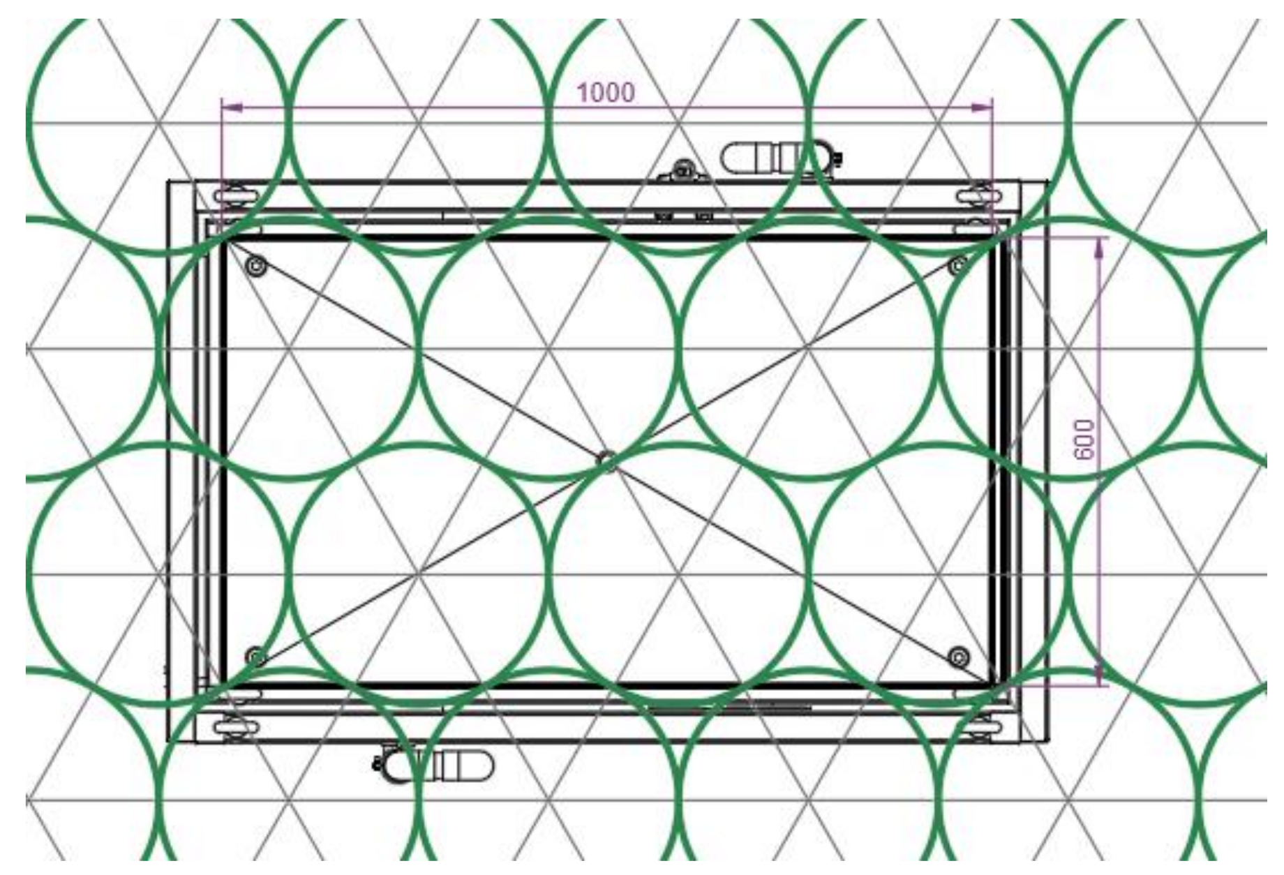
Figure 1. Dimensions in plant of the cultivation tank, of 1000 mm × 600 mm, suitable for a plantation framework of six lettuces arranged in staggered order.
Applsci 10 04865 g001
Figure 2. Perspective (a) and exploded (b) views of the developed lysimeter: (A) cultivation tank; (B) support for the cultivation tank; (C) main structure and (D) base.
Applsci 10 04865 g002
Figure 3. Three-dimensional view of the results obtained in load combination 1 for the walls of the cultivation tank of the removable weighing lysimeter. (a) Resulting displacement (mm) and (b) Von Mises equivalent stress (MPa).
Applsci 10 04865 g003
Figure 4. Three-dimensional view of the results obtained in load combination 1 for the walls of the main structure of the removable weighing lysimeter. (a) Resulting displacement (mm) and (b) Von Mises equivalent stress (MPa).
Applsci 10 04865 g004
Figure 5. Three-dimensional view of the results obtained in load combination 1 for the walls of the base of the removable weighing lysimeter. (a) Resulting displacement (mm) and (b) Von Mises equivalent stress (MPa).
Applsci 10 04865 g005
Figure 6. Installation process of the removable weighing lysimeter. (a) Base on top of undisturbed soil over. (b) Main structure and cultivation tank support. (c) Cultivation tank placed inside the main structure. (d) The cultivation tank filled with the excavated soil.
Applsci 10 04865 g006aApplsci 10 04865 g006b
Figure 7. Weight variation of the cultivation tank during a complete culture cycle (minute results).
Applsci 10 04865 g007
Figure 8. Evolution of the ETC by LP1 and ITAP lysimeters.
Applsci 10 04865 g008
Table 1. Load cases and combinations considered for the cultivation tank, the main structure and the base structure.
Load CaseValue of the Load (N/m2)Load Distribution
Cultivation tank1. Self-weight--
2. Lateral earth pressure10,000Triangular
Load combination 1Load cases 1 y 2
Main structure1. Self-weight--
2. Lateral earth pressure10,000Triangular
3. Live load A2640Uniform
4. Live load B5280Uniform
5. Live load C7920Uniform
Load combination 1Load cases 1 y 2
Load combination 2Load cases 1, 2 y 3
Load combination 3Load cases 1, 2 y 4
Load combination 4Load cases 1, 2 y 5
Base structure1. Self-weight-
2. Live load A300
3. Live load B600
4. Live load C900
Table 2. Results of the analysis for the walls of the cultivation tank, the main structure and the base structure.
Von Mises Equivalent Stress (MPa)URES: Resulting Displacement (mm)Security Factor
Cultivation tankLoad combination 112.9820.14710.76
Main structureLoad combination 136.2540.7465.633
Load combination 259.6041.1613.409
Load combination 384.9791.5762.402
Load combination 4113.8502.0001.795
Base structureLoad cases 1 and 210.8030.364
Load cases 1 and 321.6160.659
Load cases 1 and 432.4290.955
Table 3. Results of the water balance obtained with the prototype LP1 weighing lysimeter.
Water Film (mm)Mass (g)Difference In-O (g)
Inputs (In)Rainfall (R)92.449,630+3.00
Irrigation (I)399.1214,333
Condensation (C)37.820,284
Outputs (O)ETc 496.4266,562
Drainage (D)32.917,682