Article

Seismic Vulnerability of Cabinet Facility with Tuned Mass Dampers Subjected to High- and Low-Frequency Earthquakes

1
Institute of Offshore Wind Energy, Kunsan National University, Daehak-ro 558, Gunsan-si, Jeollabuk-do, Korea
2
Faculty of Technology and Technique, Quy Nhon University, Binh Dinh 55100, Vietnam
3
Department of Civil and Environmental Engineering, Kunsan National University, Daehak-ro 558, Gunsan-si, Jeollabuk-do, Korea
4
Department of Civil and Environmental Engineering, Kongju National University, Cheonan-daero 1223-24, Seobuk-gu, Cheonan-si, Chungcheongnam-do, Korea
5
Department of Civil Engineering, Gwangju University, Hyodeok-ro 277, Nam-gu, Gwangju, Korea
*
Authors to whom correspondence should be addressed.
Appl. Sci. 2020, 10(14), 4850; https://doi.org/10.3390/app10144850
Submission received: 10 June 2020 / Revised: 13 July 2020 / Accepted: 13 July 2020 / Published: 15 July 2020
(This article belongs to the Section Civil Engineering)

Abstract

:
The study investigates the collapse probability of a cabinet facility with a tuned mass damper (TMD) subjected to high- and low-frequency earthquakes. For this aim, a prototype of the cabinet in Korea is utilized for the numeric simulation. The accuracy of the finite element model is evaluated via the impact hammer tests. To mitigate the seismic response of the structure, a TMD system is developed whose properties are designed based on the outcomes from the modal analysis (i.e., modal frequencies and mode shapes). Furthermore, the influences of earthquake frequency contents on the seismic response are evaluated. The numeric analyses are conducted using a series of eighty earthquakes that are classified into two groups corresponding to low- and high-frequency motions. Finally, fragility curves are developed for the cabinet subjected to different ground motion sets. The results quantify the seismic vulnerability of the structure and demonstrate the influences of earthquake frequency contents and the vibration control system on the seismic response of the cabinet.

1. Introduction

Nonstructural components (NSCs) or secondary systems are those parts and elements suspended from, mounted on or attached to floors, roofs and walls of buildings or industrial facilities that are not intended to contribute to the structural load-bearing systems [1]. Examples of NSCs in building structures are piping systems, heating, ventilation and air conditioning units, pumps, electrical equipment, suspended ceilings, windows, bookshelves, file cabinets, furniture and appliances. Evidence from previous earthquake events has illustrated that in many cases, building structures have lost their functionality because of damage to NSCs [2,3]. Many studies in the past have been conducted to improve the understanding of the seismic performance of NSCs [4,5,6,7,8,9,10]. For this aim, different tests such as impact hammer test, sine test or shaking table test can be used [9,10,11,12]. The present study evaluates the seismic performance of electrical file cabinets and the effect of TMDs on the improvement of the performance of these secondary systems.
According to the operation history of nuclear power plants (NPPs) in over the world, some plants had been completely shut down during or after an earthquake because of damages on its components. For example, in March 2011, the Tohoku earthquake in Japan and subsequent tsunami caused severe consequences to the NPPs in Fukushima Daiichi and serious nuclear disaster, which directly affected the ambient environment and human life. This event affected various NPPs simultaneously at a site when eleven reactors of four plants had to be shut-down immediately [13,14]. The Gyeongju (2016) and Pohang (2017) earthquakes that occurred with high-frequency contents had the potential damage to the continued functionality of related equipment in NPP secondary structures [15]. Additionally, the Virginia earthquake in the US (2011) was known as a motion with the intensity measure (IM) exceeded both operating basis and design basis earthquakes level at North Anna Station, although there were no significant damages after carrying out post-earthquake investigations [16]. Therefore, the studies on the seismic response of primary, secondary structures, and their components are always necessary.
In the context of performance-based earthquake engineering (PBEE), the earthquake frequency content is known as an important parameter that can significantly affect the seismic response of the structure. For a high-frequency structure as an electrical cabinet, the high-frequency ground motion can amplify the structural response [15]. In this study, two suites of ground motions, including high-frequency (HF) and low-frequency (LF) earthquakes are considered where an earthquake is considered as low-frequency when its dominant frequency value is less than 10 Hz [17].
Electric cabinets play an important role in the operation of nuclear power plants; thus, their seismic performances need to be considered sufficiently. Being an indispensable part of NPP, there are numerous electrical devices attached inside the cabinet, such as switchboards, lighting panels, etc., and these functional devices are sensitive to the response of the main structure. For instance, the sensitivity of the acceleration response of the fusible switches and circuit breakers depends on their relative location in the cabinet [18,19,20]. For these nonstructural components, the grouping effects that refers to the combination of the cabinet facility are one of the key aspects that have been investigated in several works [21,22,23]. Salman et al. [21,22] developed the seismic fragility curves of the cabinet following two design standards, namely earthquake loss estimation methodology (HAZUS) [24] and Nuclear Regulatory Commission (NUREG) [25].
Numerous researchers have tried to invent various seismic control devices that help to mitigate unexpected vibration of the structural and nonstructural systems by dissipating the input seismic energy [26,27,28,29,30,31]. In order to assess the efficiencies of a structure, important requirements should be satisfied, such as stability, serviceability, etc. One of the effective methods is the use of tuned mass damper (TMD), which was first proposed in 1909 [26]. Many research studies have been carried out to improve the efficiency of TMD systems for various dynamic applications. TMDs were first proposed for the mitigation of wind-induced vibrations. Later, TMDs were also implemented for reducing the effects of seismic excitations [27,28]. Studies in the past have illustrated shortcomings associated with the use of TMDs for the mitigation of seismic responses of structures. These shortcomings arise primarily from the nonlinear behavior of the primary structure in severe seismic loading and the associated period shift that causes a detuning [30,32]. As long as the structure behaves within the linear range of behavior, which is the case in the present study, this shortcoming is less pronounced. In the field of nuclear engineering, the TMD systems have been popularly used to mitigate the seismic response of structures [33,34,35,36,37]. For instance, Kwag et al. developed multiple TMDs to reduce the vibration of the piping system in NPPs due to earthquakes [34,37]. Only a few studies in the past have used TMDs for the mitigation of the responses of nonstructural components. Anajafi [38] illustrated that the use of a higher-mode TMD could significantly reduce the spikes of floor acceleration spectra of building structures mitigating the seismic force demands on nonstructural components. Tan et al. [39] used TMDs to reduce the seismic responses of piping systems. Cho et al. [33] used a TMD to improve the seismic response of an electric facility.
This study aims to fill the technical gaps which have not been particularly highlighted in the present literature. The main objective is to evaluate the seismic responses of electrical cabinet subjected to the high- and low- frequency ground motions. The TMD is also used as a control device, which can reduce the response of the electric cabinet to improve the stability of electrical components. Based on the obtained outcomes, the correlation of seismic performance between two groups of earthquakes and two numeric models with and without applying TMD is investigated.

2. Numeric Modeling of NPP Equipment

2.1. Structural Configurations

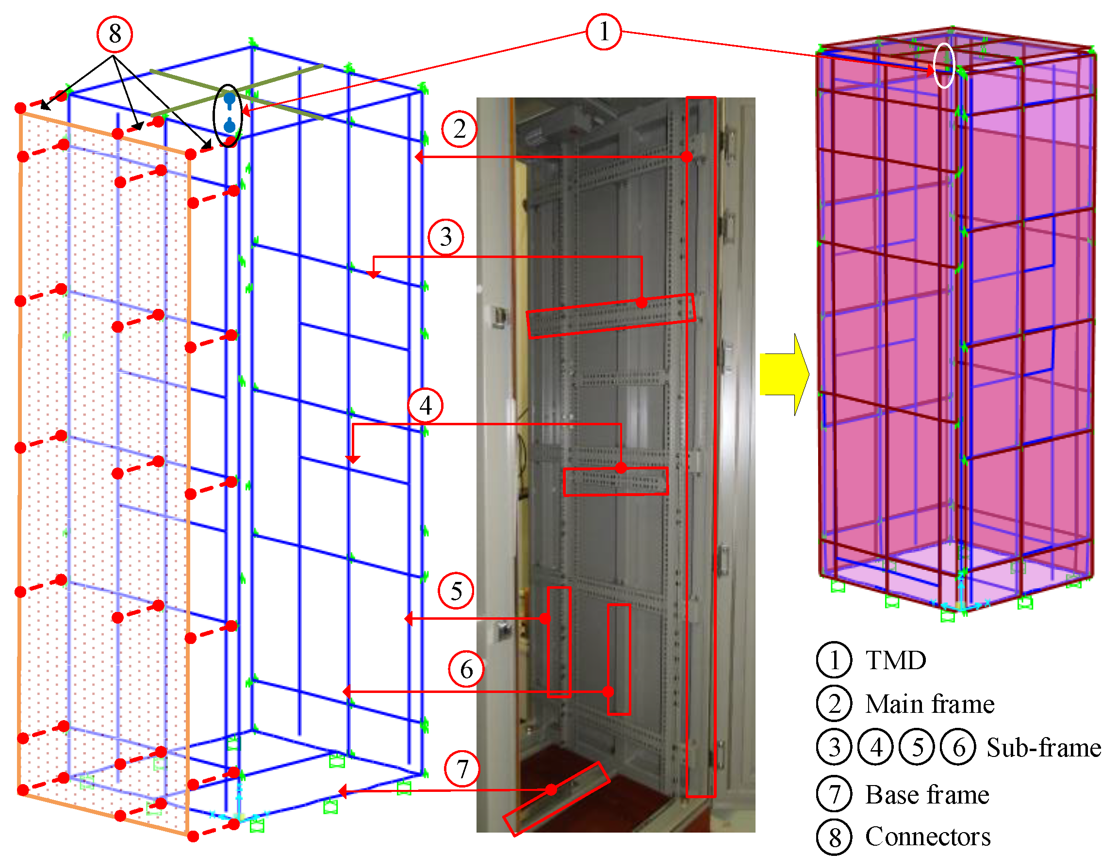
In this study, an electrical cabinet provided by Innose Tech company in Korea was used as a representative of NPP equipment [11,21]. This prototype was used to carry out some experimental tests for assessing the seismic performance of NPP facilities. The details of the configuration are shown in Figure 1a. The specifications of the components, including plates, subframes, mainframes, were assigned to SS400 steel. The material characteristics had 200 GPa of Young’s modulus, the Poisson’s ratio ( v ) and density ( ρ ) were 0.3 and 7850 kg / m 3 , respectively. The external dimensions of the cabinet were 800×800×2100 (mm×mm×mm), and its weight was 287 kg. The thickness of the plates was 2.3 mm, and the detailed cross-sections of the electric cabinet’s components include C-shape and rectangular, as expressed in Figure 1b.
The finite element model (FEM) of the electric cabinet was created by using SAP2000 software (Figure 1c), in which the linear beam and shell elements were used to simulate the frame and plate members, respectively. Torsion and warping [40] of plate members of the structure were ignored in this study. The link elements were used to model their connections. Particularly, the connections between the plates and frames were simulated as rigid link elements. The hinges between doors and frames were also considered to be fixed at five degrees of freedom; only the rotation around the hinge axis was released. Meanwhile, the locks between panels and frames were fixed at three translational degrees of freedom. For the boundary condition of the structure, a total of 8 bolts connect the base-frames with the floor. These connections were assumed to be fixed at all degrees of freedom.
In this study, the electrical cabinet was assumed to respond elastically with a 5% inherent (viscous) damping. A few experimental studies have shown that the viscous damping ratio of typical NSCs could be well below the conventional value of 5% [41,42]. Previous numeric studies had illustrated that the value of NSCs damping ratio could significantly affect the acceleration demands on NSCs, especially when the frequency of NSCs was close to those of the supporting structures [1,43]. Furthermore, a few previous studies had shown that the inelastic behavior of NSCs could significantly reduce their seismic force and displacement demands, especially for tuned NSCs [44,45,46]. Given the importance of the damping ratio and the nonlinear behavior of NSCs identified by the above-mentioned studies, future research works on electrical cabinets should consider the effect of these parameters.

2.2. Validation of the Numeric Model

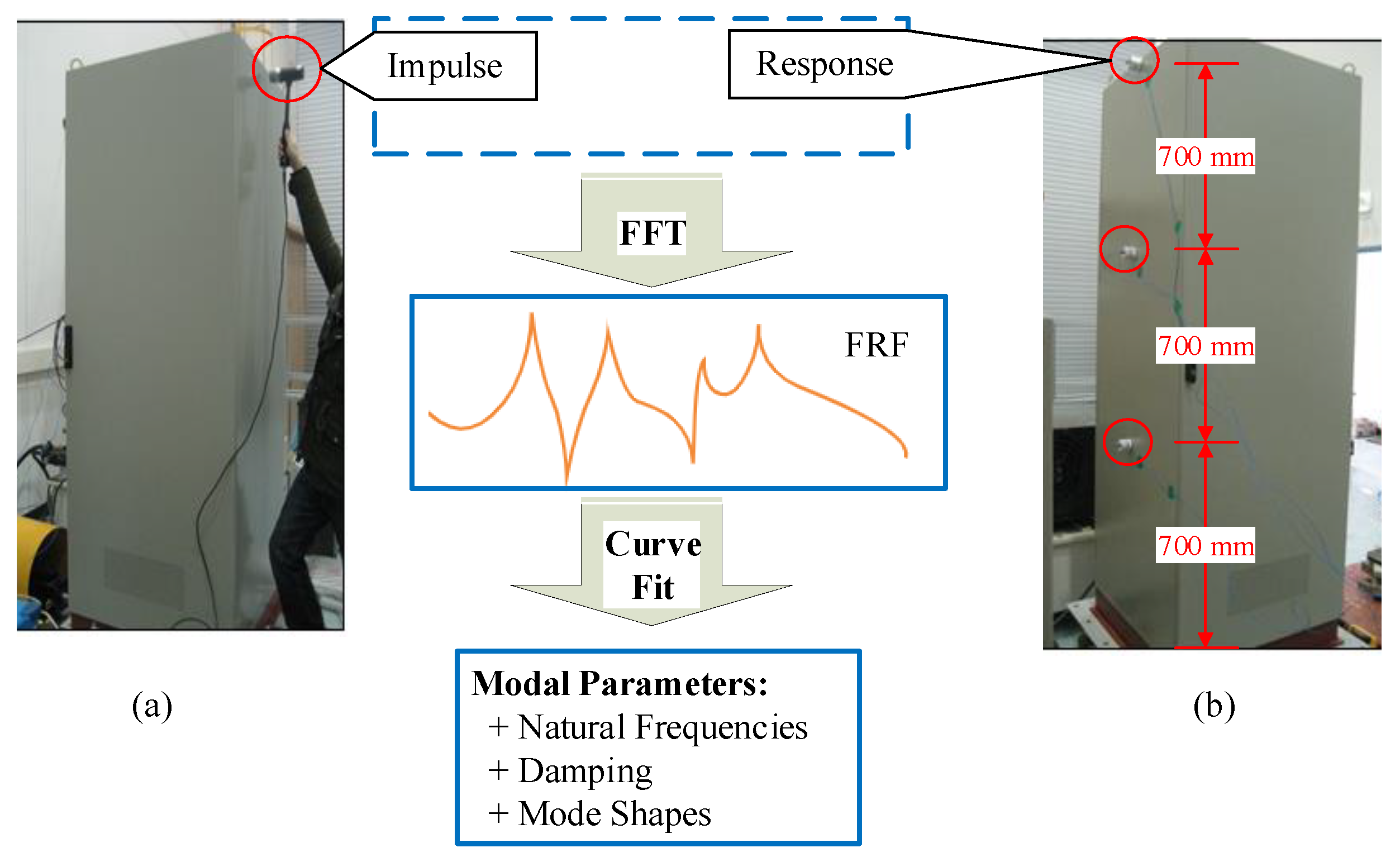
In this study, the impact hammer test was performed to identify the dynamic characteristics of the cabinet. A schematic of the test is shown in Figure 2. Three 393B04 accelerometers were installed along the height of the cabinet (Figure 2b) to record the response from the impact force (Figure 2a).
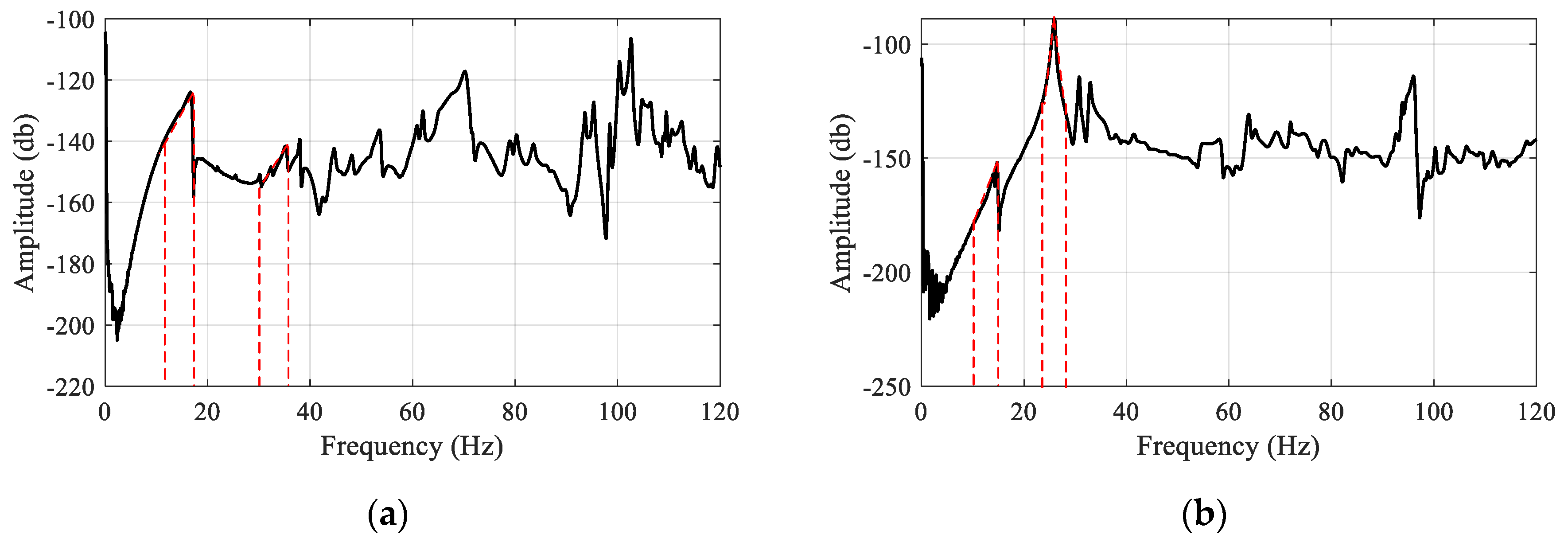
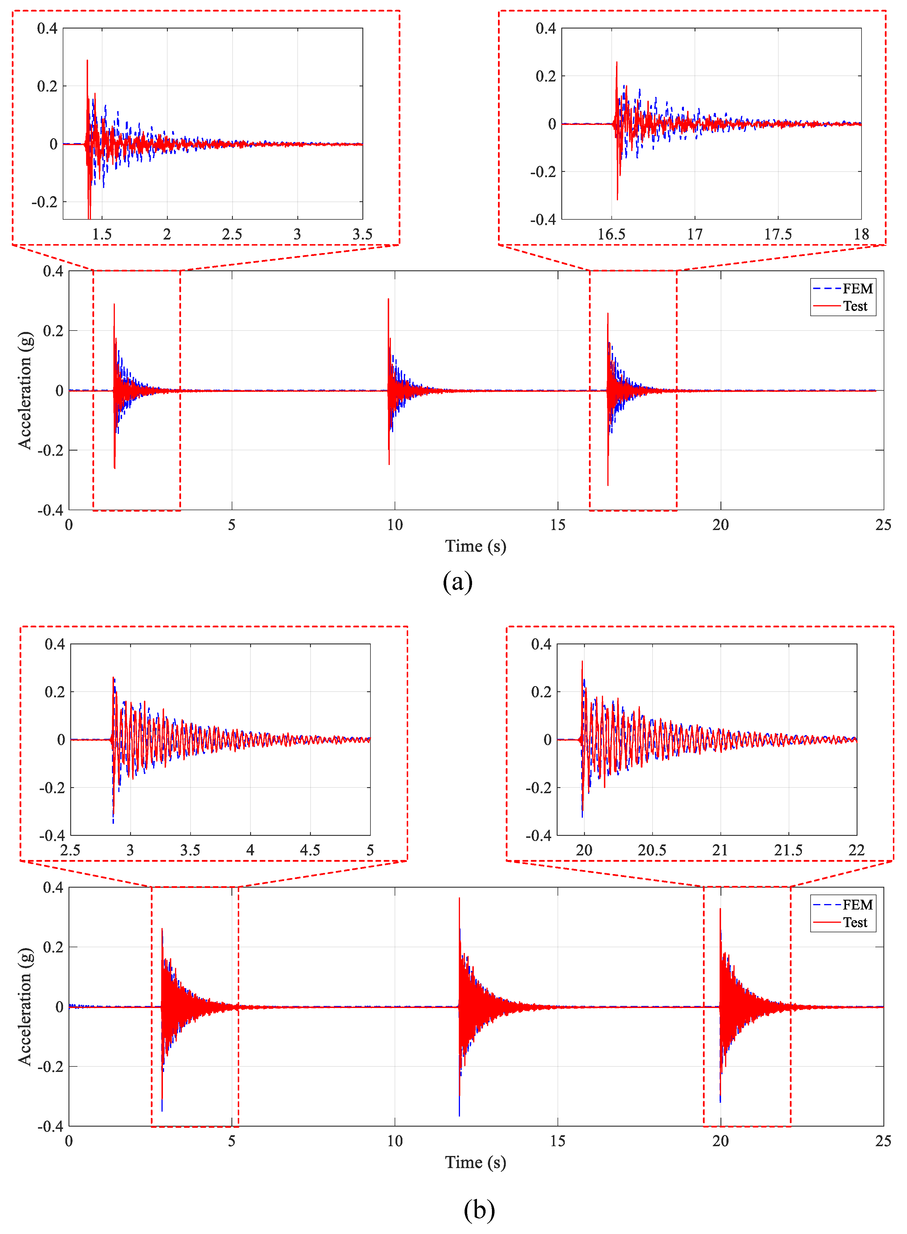
The acceleration responsed from the experimental tests were first obtained. Then the frequency domain decomposition (FDD) method [47,48] was used to extract the natural frequencies of the cabinet, as plotted in Figure 3. In order to verify the numeric model, the acceleration responses at the cabinet’s top were taken in both directions (front-to-back and side-to-side) and compared with the test, as shown in Figure 4. As can be seen in the figure, the outcomes from FEM had a good agreement with those from the test. It is worth mentioning that there was a minor difference in the response in the front-to-back direction. This can be explained due to the effect of shim and hinge connections between doors and main frames. In the numeric model, these connectors were assigned as the link elements; thus, the response may differ with the test.

2.3. Modal Analysis

This section presents the dynamic characteristics of the cabinet that were important to design a vibration control device for the structure. As discussed previously, the electric cabinet was built up with frame and plate members; thus, the structure had global modes (dominated by the deflection of the cantilever frame as a whole) and local modes (the steel plate behavior of the side panels and doors).
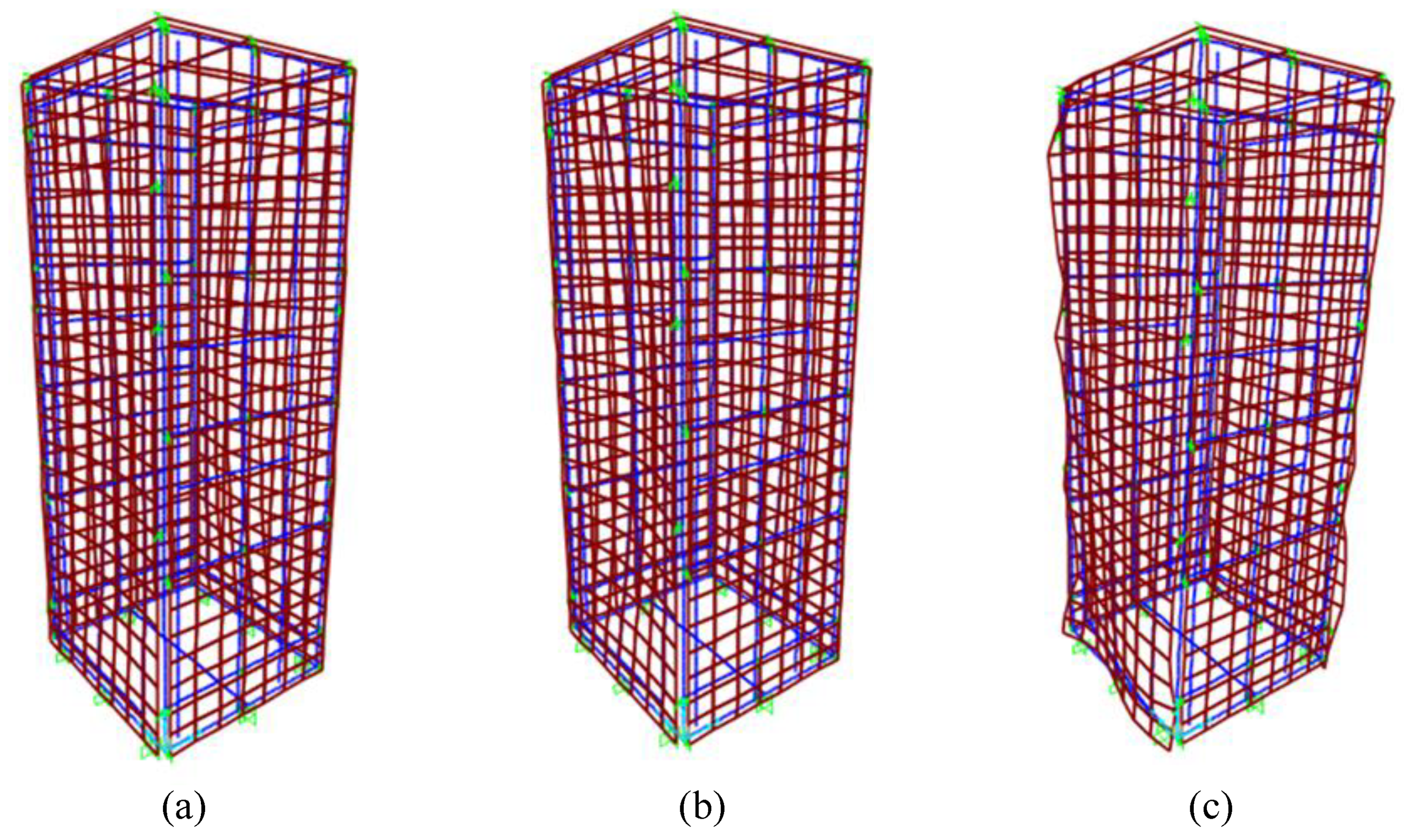
For modal analysis, one hundred modes were defined to calculate the modal participation mass ratio (MPMR). Figure 5 presents the dynamic characteristics (i.e., mode shape, natural frequency, and MPMR) of the first three modes. The obtained results indicated that the dominant dynamic behavior of the cabinet was controlled by the third mode as its MPMR was significantly higher than any other modes of vibration. The modal mass of the cabinet was calculated as follows [49]:
m o d a l   m a s s = i = 1 n m i × δ i j 2
in which n was the number of nodes of the structure; m i was the mass of i t h node and δ i j was the eigenvector of i t h node and j t h mode.

2.4. Modeling with Tuned Mass Damper (TMD)

2.4.1. Mathematical Modeling of the TMD System

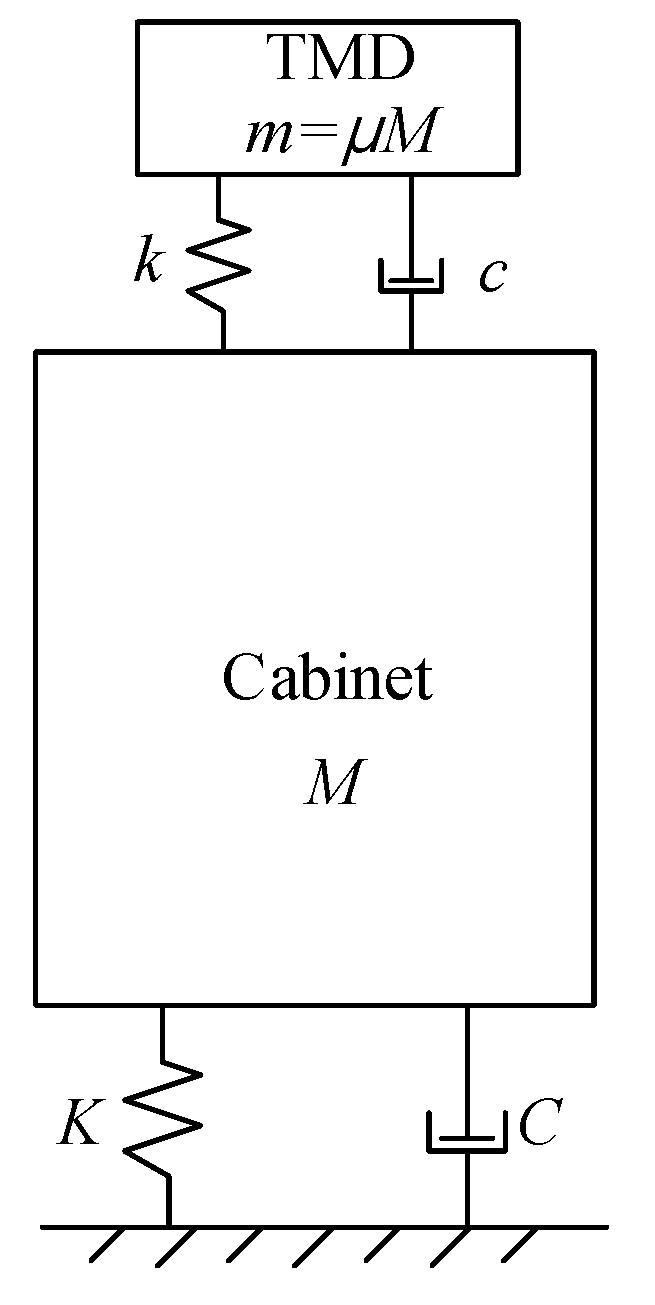
A TMD is a substructure that serves as a vibration absorber for the main structure [50,51,52,53,54]. A TMD device consisting of a spring (with stiffness k ), a mass ( m ) and a damper (coefficient c ) is attached to a structure having stiffness ( K ) , a mass ( M ) and a damping ( C ) to mitigate undesirable vibrations. In other words, TMD helps to reduce the response of the structure under the effects of seismic loading condition by increasing considerably modal damping in some first important modes. The simple explanation of the TMD device is described in Figure 6.
In this study, in order to validate the effectiveness of the TMD device, the seismic response of the electric cabinet with and without TMD subjected to different groups of ground motion are analyzed and compared to each other.
The specifications of a TMD device include its tuning, mass and damping ratio. The ratio between the fundamental frequency of the TMD ω t and the main structure ω o is defined as the tuning ratio f , which expressed in the Equation (2).
f = ω t / ω o
Moreover, the mass ratio is defined by Equation (3)
μ = m / M
where M is the generalized mass for a certain mode of vibration of the structure. The damping ratio of the TMD device is defined by Equation (4).
ξ = c / 2 m ω t
To reduce the response of the main structure under earthquake loading conditions, many studies were conducted to assess the effects of parameters f and ξ for a given μ . According to Kaynia et al. [55], the optimum mitigation in the response of the main structure can be achieved when f is close to unity.

2.4.2. Optimum TMD Parameters

Through the modal analysis, the modal participation mass ratios for the dominant modes are determined. The parameters of the TMD are then defined as a function of the MPMR. The following equations are used to calculate the optimal frequency, f o p t and damping ratio, ξ o p t , of TMD [56]. Although these equations are applied for stochastic base excitations, in this study they are used for the actual ground motions due to their simplicities.
f o p t = 1 1 + μ
ξ o p t = 3 μ 8 ( 1 + μ )
in which μ is the mass ratio of TMD. The parameters of TMD are tabulated in Table 1.

2.4.3. Structural Modeling with TMD System

Based on the above discussion, a finite element model with TMD is developed, as shown in Figure 7. The zero-length link element with the designed parameters in Table 1 is used to simulate the TMD. The link element has two nodes in which the first point is connected to the top plate of the electrical cabinet and the second point is used to assign the mass of TMD. Additionally, the first point is considered to be free for the rotational axis. The first point of the link element is placed at the center of the top plate of the cabinet.

3. Ground Motion Selection

The characteristics of any ground motions are expressed by some significant engineering factors such as amplitude (i.e., peak ground acceleration, PGA), predominant frequency or duration, etc. In the case of PGA, it just reflects the peak value of acceleration data, and it is difficult to state that an earthquake with greater PGA value has more effects than the lower ones. Besides that, predominant frequency is a crucial factor, which can be used for assessing the dynamic characteristics [57], especially for the performance of the frequency-sensitive electrical components in the electric cabinet.
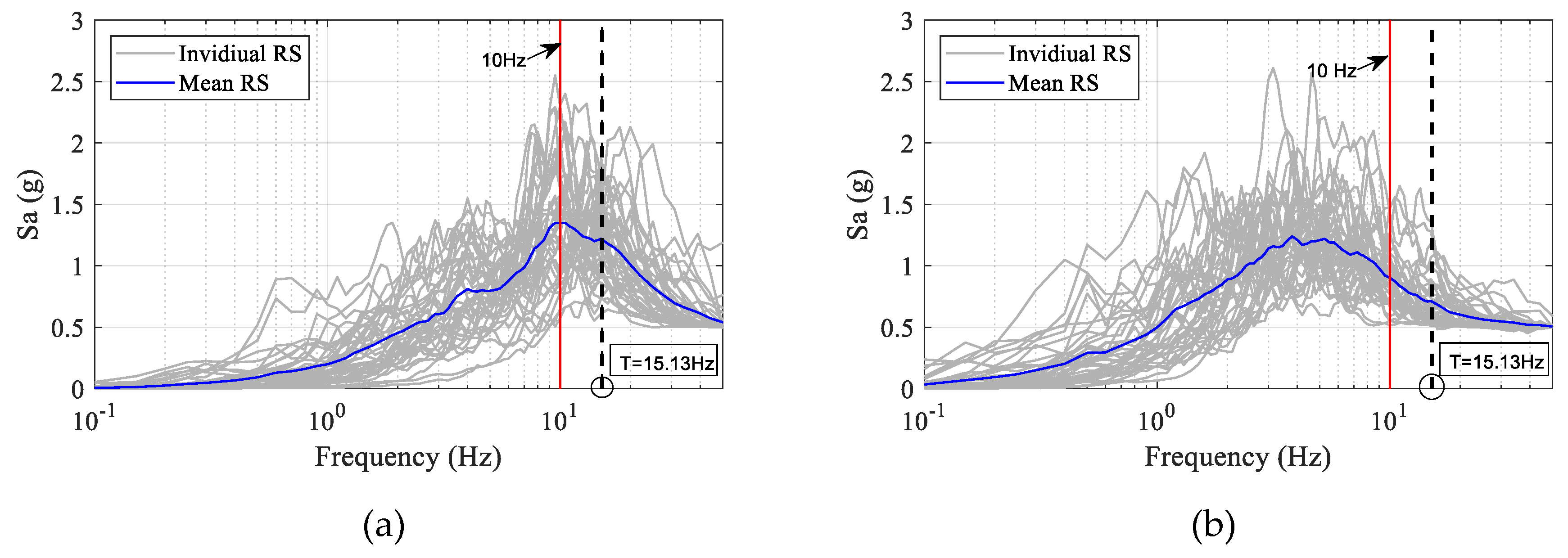
According to Gupta et al. [15], the high-frequency ground motions can amplify the structural response of a dominant high-frequency structure as the cabinet. Thus, the frequency content of the earthquake is considered in this study. Eighty records of ground motion are chosen from the Pacific Earthquake Engineering Research (PEER) center and historical earthquakes in Korea. These data are classified into two groups based on the different frequency contents, including 40 records are in the high-frequency, and the rest 40 records are in the low-frequency group. All data are scaled to a given value of PGA (0.5 g) and used as the input ground motion for the numeric model.
The response spectrum can be used to identify the frequency content type of seismic excitation. In this study, the predominant frequency of a ground motion can be estimated by evaluating the predominant period. This is the period at which the maximum spectral response is observed. The threshold value of 10 Hz is used to distinguish the low- and high-frequency motions. In other words, if the dominant frequency of an earthquake is approximately smaller than 10 Hz, it is considered as low-frequency excitation. In contrast, it is considered a high-frequency motion. Response spectra of two groups of earthquakes corresponding to high- and low-frequency are shown in Figure 8.

4. Results and Discussions

All of the earthquake records are applied to the horizontal direction of the numeric model as the input excitations. The performance of the structure is obtained via time history analyses. According to the Nuclear Regulatory Commission [25], the guideline for developing the probabilistic fragility levels of electrical devices (power supply, panel board, switchboard, etc.) in NPPs, the acceleration response is utilized as damage measurement because of its practical aspect. Therefore, in this study, the acceleration response at the cabinet’s top is chosen as the crucial seismic response.

4.1. Comparison of Uncontrolled and Controlled Responses

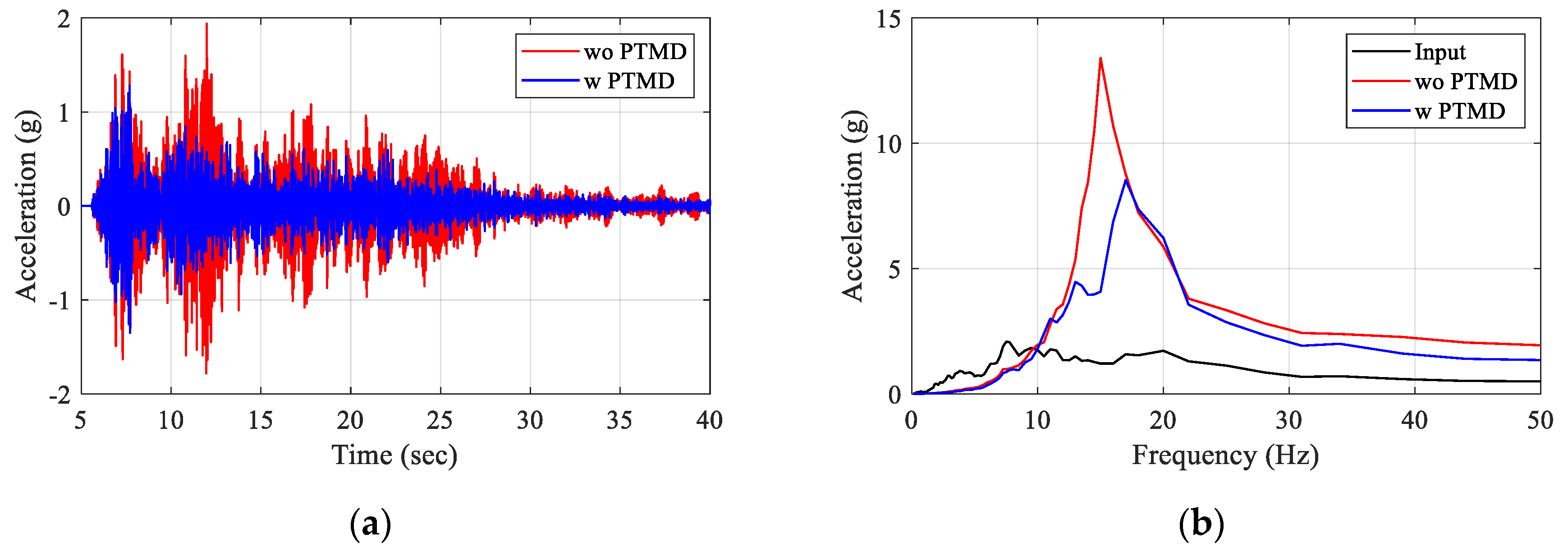
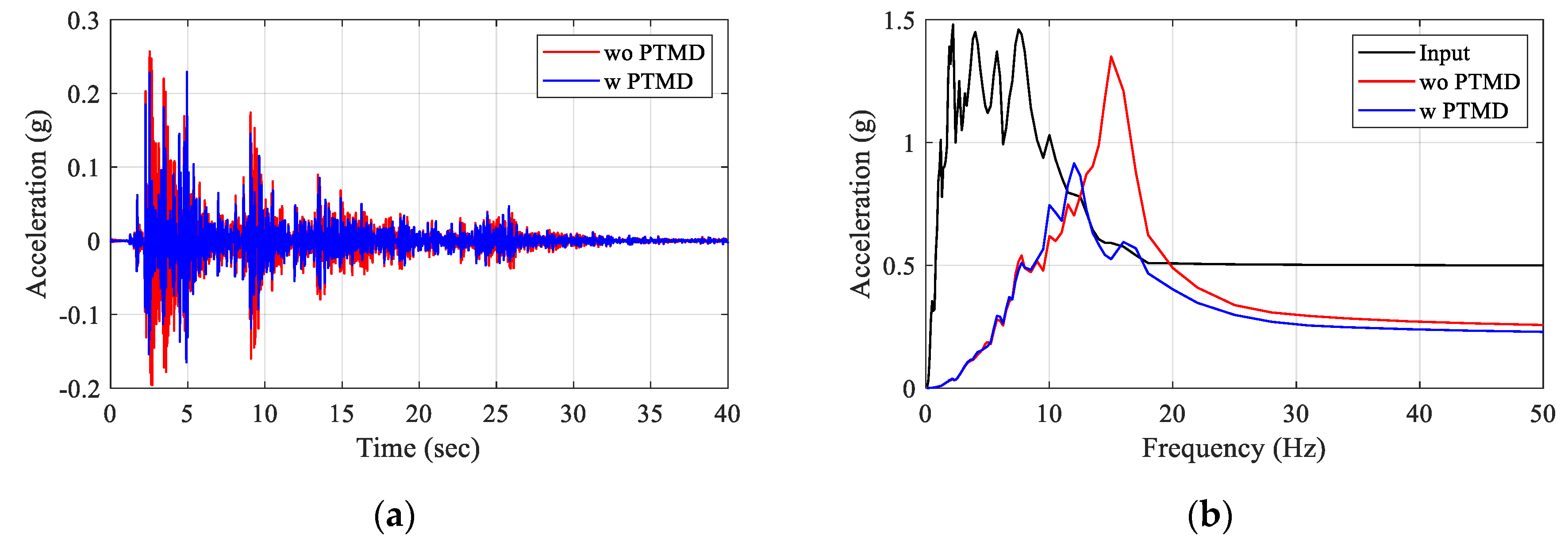
Figure 9a, Figure 10a illustrate the time history of the acceleration responses of the cabinet subjected to two specific records, which characterized for high-frequency (Pohang) and low-frequency (Impevall) earthquakes. As seen in these figures, the significant reductions in acceleration response can be achieved with a TMD system. Thus, the stability of the electric cabinet can be improved to protect the installed electrical devices. Moreover, the elastic response spectrum analysis of 5% viscous damping is also performed, as illustrated in Figure 9b, Figure 10b. The maximum acceleration in the cases of using TMD can be decreased by up to 30% compared with those from the without TMD case.

4.2. Effect of Frequency Contents on the Seismic Responses

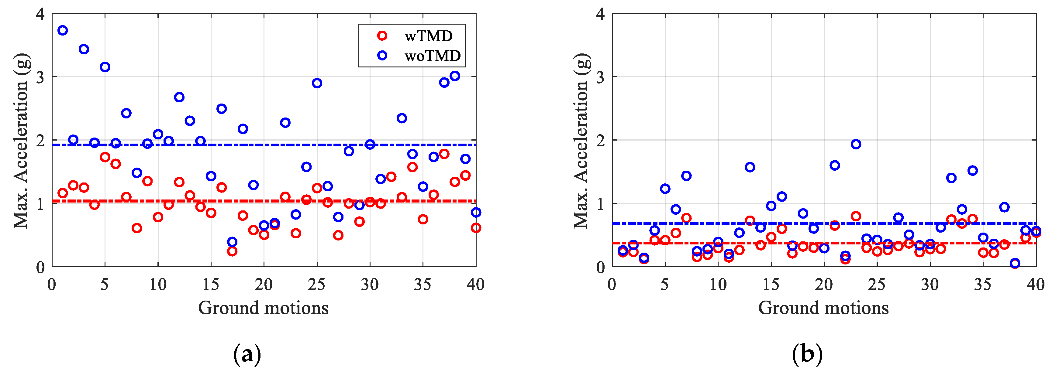
To clarify the effects of the frequency contents on the seismic responses of the electric cabinet, a comparison between the responses obtained under the two ground motion groups is illustrated in Figure 11. The scatter points in each subfigure are the maximum acceleration values of the structural response in both cases with and without TMD. The horizontal lines are the mean values of each case. As can be seen from these figures, the mean value of the maximum acceleration in both cases of high- and low-frequency ground motions indicates that TMD is an effective device to significantly mitigate the acceleration response of the cabinet by absorbing undesirable dynamic excitation.
Another finding can be explained through the acceleration amplification factor ( A A F ) that is defined as the ratio of mean acceleration response at the top of the cabinet ( A c a b i n e t ) , and the PGA of input excitation ( A e x c i t a i o n , 0.5 ) that is equal to 0.5 g. The A A F is calculated as follows:
A A F = A c a b i n e t / A e x c i t a i o n , 0.5
The comparative results of A A F are tabulated in Table 2. In the case of without TMD, the A F F value of HF earthquakes is 3.84 that greater than three times compared to the LF group. When TMD is considered, a reduction of around 50% compared to without TMD system is found for both HF and LF earthquakes, corresponding to the A F F values of 2.07 and 0.74, respectively. It is found that the structural response of the cabinet depends strongly on the variation of the earthquake frequency contents.
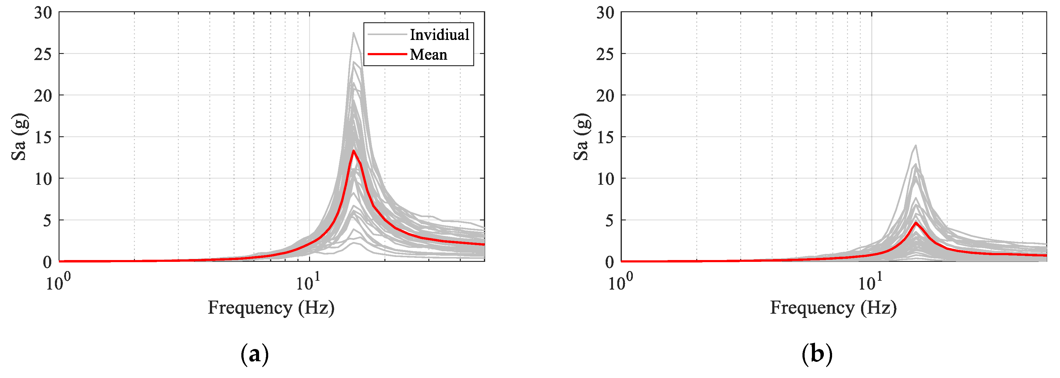
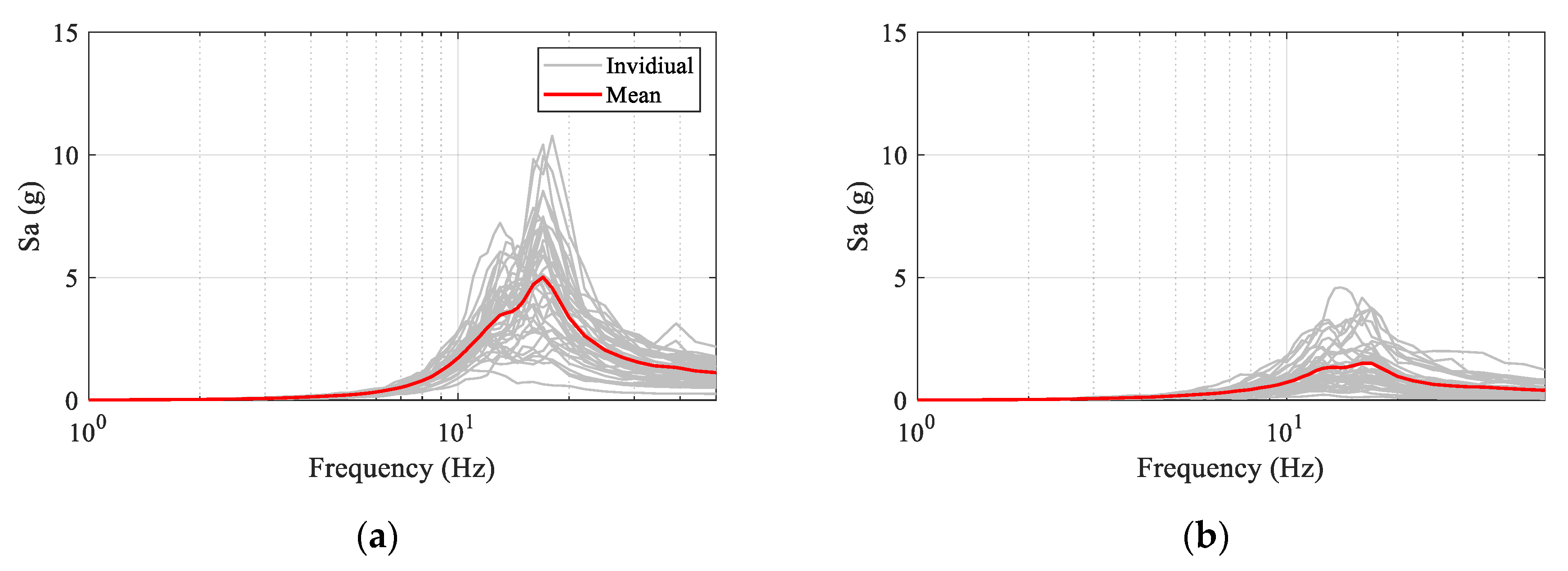
In addition, the spectral acceleration of the electric cabinet according to the numeric model with and without TMD in Figure 12 and Figure 13. From these figures, it can be seen that the models with TMD have lower spectral acceleration responses compared to those models without the TMD system. Moreover, the trends of spectral acceleration of LF earthquakes in both cases with and without TMD are the same with the acceleration responses in Figure 11, with a smaller response compared to the HF group. This leads to the conclusion that the HF earthquakes amplify the structural response of the cabinet structure significantly.

4.3. Fragility Analysis

Fragility analysis is used widely for assessing the seismic performance of structures. Several theories can be used to carry out the fragility analysis and one of them is incremental dynamic analysis (IDA), which involves numerous structural analyses corresponding to different ground motion records [58]. Each recorded earthquake is scaled into various intensity levels as long as the whole range from elastic to collapse of the structure can be covered.
This section describes the probability of failure of the structure based on its damage state, which is characterized by an engineering demand factor and intensity measure. There are several types of intensity measures such as PGA, PGV, etc., which can be used to estimate the probability of failure of a structure via fragility curves [11,13,19,21,59]. In this research, PGA is used as a good indicator for time history analysis [60,61]. As reported by the Nuclear Regulatory Commission [25], the electrical cabinet contains many electrical devices. Thus, the acceleration response at the top of the cabinet is considered as the limit state (LS) to develop fragility curves in this study. The LS value is defined when the zero period acceleration (ZPA) at 2% damping comes to 1.8 g.
The fragility function is defined by a lognormal cumulative distribution function as [62]:
P ( C | I M = x ) = Φ [ ln ( x θ ) β ]
where P ( C | I M = x ) is the probability that a ground motion with I M = x will cause the collapse of the structure; θ is the mean value of the fragility curve, corresponding to the I M level with 50% probability of exceedance and β is the standard deviation of ln I M . These parameters are defined by Equations (8) and (9) [62].
ln θ = 1 n i = i n ln I M i
β = 1 n 1 i = 1 n ( ln ( I M i / θ ) ) 2

4.3.1. Effects of the Vibration Control System on the Seismic Vulnerability of the Cabinet

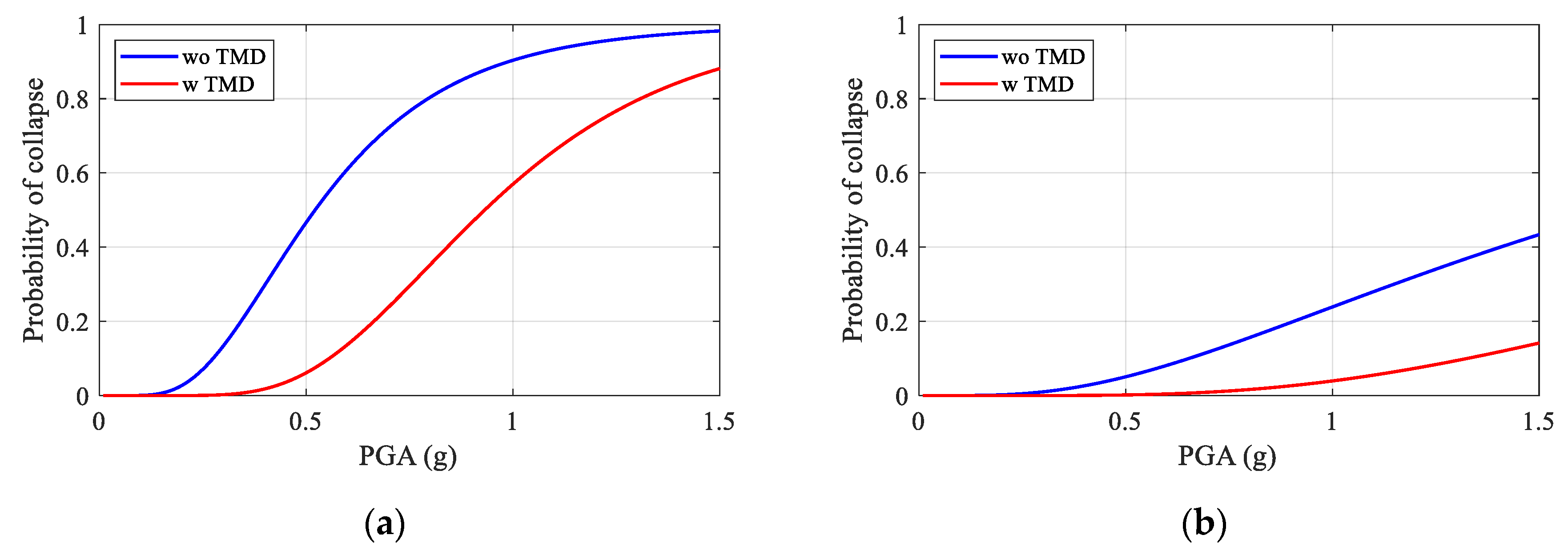
Figure 14 shows a comparison of fragility curves for the electric cabinet when subjected to various ground motion groups. For each subfigure, the probability of the exceedance of the electrical cabinet installed with and without a TMD system is plotted. The mean ( θ ) and the standard deviation ( β ) are determined from the Equations (8) and (9) and summarized in Table 3.
From figure, it can be seen that the structural model without TMD would be more vulnerable than that model with the TMD system. The differences between the fragility curves are explained due to the differences in the acceleration responses of the structure. It is worth mentioning that due to the placement of the TMD at the top of the cabinet, the top response has reduced significantly.

4.3.2. Effects of Frequency Contents on the Seismic Vulnerability of the Cabinet

Figure 15 compares the probability of the exceedance of the acceleration response of the cabinet from the defined damage threshold while subjected to the HF and LF earthquakes. In the case of without TMD, the median acceleration value for HF and LF groups are 0.521 g and 1.699 g, respectively (Table 3). Whereas for the model equipped with TMD, there is a dramatic change in the fragility curves, corresponding to values of 0.932 g and 2.833 g for HF and LF data, respectively. This leads to the conclusion that the structural model under HF motions would be more vulnerable. This can be attributed to the reason that the high-frequency pulses of the ground motions can amplify the structural response of high-frequency structures such as the electrical cabinet.

5. Conclusions

Collapse fragility of an electric cabinet in nuclear power plants with a tuned mass damper (TMD) under earthquake excitation is presented in this work. For this aim, the finite element model is developed and verified with the experimental test. The dynamic characteristics (such as natural frequencies and mode shapes) from the FEM are used to identify the damper. The time history analyses are carried out to determine the seismic performance of the equipment subjected to two specific records, which characterized for high-frequency and low-frequency ground motions. Finally, the fragility curves are developed to estimate the probabilistic failure of the structure.
Two numeric models with and without a TMD system are considered to demonstrate the effectiveness of the vibration control system on the seismic performance of an electrical cabinet. The obtained results indicate that: (1) The TMD is an effective device to reduce the seismic response of the cabinet structure. This aspect is meaningful in controlling the structural response to protect the installed inside electrical devices; (2) More than 30% of the reduction of the response is found for the case with an installed control system.
Two comparative earthquake groups with high- and low-frequency contents are used to investigate their influences on the response of the high-frequency electrical cabinet. From the observed results, it can be concluded that: (1) The structural response of the cabinet depends strongly on the frequency contents of the seismic input. More vulnerability is found for the high-frequency motions; (2) The defined AAF of the cabinet address that the HF motions are greater approximately three times compared to LF motions in both cases with and without TMD a TMD system.
In order to evaluate the seismic vulnerability of the cabinet with a TMD subjected to high- and low-frequency earthquakes, the fragility analysis is developed by performing incremental dynamic analysis. The results show that the fragility functions under HF and LF motions are quite different, and it has the same trend for two models with and without a control system. Most vulnerability is found for the model without TMD system under HF earthquakes.
In the present study, the frequency contents of the seismic input are considered without the consideration of the resonance effects. Hence, further works should be conducted to consolidate the influences of the seismic characteristics on the structural response of the cabinet.

Author Contributions

Conceptualization, T.-T.T. and S.C.; methodology, A.-T.C. and D.K.; validation, T.-T.T. and D.K.; writing—original draft preparation, A.-T.C. and T.-T.T.; writing—review and editing, T.-T.T. and S.C. All authors have read and agreed to the published version of the manuscript.

Funding

This research was funded by the Korea Institute of Energy Technology Evaluation and Planning (KETEP) and the Ministry of Trade, Industry & Energy (MOTIE) of the Republic of Korea grant number no 20171510101960.

Acknowledgments

This work was supported by the Korea Institute of Energy Technology Evaluation and Planning (KETEP) and the Ministry of Trade, Industry & Energy (MOTIE) of the Republic of Korea (No. 20171510101960) and this study was conducted by research funds from Gwangju University in 2020.

Conflicts of Interest

The authors declare no conflict of interest.

References

  1. Anajafi, H.; Medina, R.A. Damping modification factor for elastic floor spectra. Bull. Earthq. Eng. 2019, 17, 6079–6108. [Google Scholar] [CrossRef]
  2. Sullivan, T.J.; Calvi, P.M.; Nascimbene, R. Towards improved floor spectra estimates for seismic design. Earthq. Struct. 2013, 4, 109–132. [Google Scholar] [CrossRef]
  3. Filiatrault, A.; Sullivan, T. Performance-based seismic design of nonstructural building components: The next frontier of earthquake engineering. Earthq. Eng. Eng. Vib. 2014, 13, 17–46. [Google Scholar] [CrossRef]
  4. Rodriguez, M.E.; Restrepo, J.I.; Carr, A.J. Earthquake-induced floor horizontal accelerations in buildings. Earthq. Eng. Struct. Dyn. 2002, 31, 693–718. [Google Scholar] [CrossRef]
  5. Singh, M.P.; Moreschi, L.M.; Suárez, L.E.; Matheu, E.E. Seismic Design Forces. II: Flexible Nonstructural Components. J. Struct. Eng. 2006, 132, 1533–1542. [Google Scholar] [CrossRef]
  6. Adam, C.; Furtmüller, T. Response of nonstructural components in ductile load-bearing structures subjected to ordinary ground motions. In Proceedings of the 14th World Conference on Earthquake Engineering, Beijing, China, 12–17 October 2008. [Google Scholar]
  7. Adam, C.; Furtmüller, T.; Moschen, L. Floor response spectra for moderately heavy nonstructural elements attached to ductile frame structures. In Computational Methods in Applied Sciences; Springer: New York, NY, USA, 2013; Volume 30, pp. 69–89. [Google Scholar]
  8. Anajafi, H.; Medina, R.A. Lessons Learned from Evaluating the Responses of Instrumented Buildings in the United States: The Effects of Supporting Building Characteristics on Floor Response Spectra. Earthq. Spectra 2019, 35, 159–191. [Google Scholar] [CrossRef]
  9. Di Sarno, L.; Magliulo, G.; D’Angela, D.; Cosenza, E. Experimental assessment of the seismic performance of hospital cabinets using shake table testing. Earthq. Eng. Struct. Dyn. 2019, 48, 103–123. [Google Scholar] [CrossRef] [Green Version]
  10. Filiatrault, A.; Matt, H. Seismic response of high voltage electrical transformer-bushing systems. J. Struct. Eng. 2006, 132, 287–295. [Google Scholar] [CrossRef]
  11. Tran, T.-T.; Kim, D. Uncertainty quantification for nonlinear seismic analysis of cabinet facility in nuclear power plants. Nucl. Eng. Des. 2019, 355, 110309. [Google Scholar] [CrossRef]
  12. Nguyen, P.C.; Doan, N.T.N.; Ngo-Huu, C.; Kim, S.E. Nonlinear inelastic response history analysis of steel frame structures using plastic-zone method. Thin Walled Struct. 2014, 85, 220–233. [Google Scholar] [CrossRef]
  13. Cao, A.T.; Tran, T.T.; Nguyen, T.H.X.; Kim, D. Simplified Approach for Seismic Risk Assessment of Cabinet Facility in Nuclear Power Plants Based on Cumulative Absolute Velocity. Nucl. Technol. 2019, 206, 1–15. [Google Scholar] [CrossRef]
  14. Suehiro, S.; Sugimoto, J.; Hidaka, A.; Okada, H.; Mizokami, S.; Okamoto, K. Development of the source term PIRT based on findings during Fukushima Daiichi NPPs accident. Nucl. Eng. Des. 2015, 286, 163–174. [Google Scholar] [CrossRef]
  15. Gupta, A.; Cho, S.G.; Hong, K.J.; Han, M. Current state of in-cabinet response spectra for seismic qualification of equipment in nuclear power plants. Nucl. Eng. Des. 2019, 343, 269–275. [Google Scholar] [CrossRef] [Green Version]
  16. Li, Y.; Manoly, K. GI 199 and 2011 Mineral, VA Earthquake Impact to North Anna Nuclear Power Plant. In Proceedings of the 15th World Conference on Earthquake Engineering, Lisbon, Portugal, 24–28 September 2012. [Google Scholar]
  17. Nguyen, D.D.; Thusa, B.; Han, T.S.; Lee, T.H. Identifying significant earthquake intensity measures for evaluating seismic damage and fragility of nuclear power plant structures. Nucl. Eng. Technol. 2019, 52, 192–205. [Google Scholar] [CrossRef]
  18. Goodno, B.J.; Gould, N.C.; Caldwell, P.; Gould, P.L. Effects of the January 2010 haitian earthquake on selected electrical equipment. Earthq. Spectra 2011, 27, 251–276. [Google Scholar] [CrossRef]
  19. Tran, T.T.; Cao, A.T.; Nguyen, T.H.X.; Kim, D. Fragility assessment for electric cabinet in nuclear power plant using response surface methodology. Nucl. Eng. Technol. 2019, 51, 894–903. [Google Scholar] [CrossRef]
  20. Tran, T.T. Modelling and Simualtion of Uncertianties for Nuclear Facilities and Soil Deposits; Kunsan National University: Gunsan, Korea, 2020. [Google Scholar]
  21. Salman, K.; Tran, T.T.; Kim, D. Grouping effect on the seismic response of cabinet facility considering primary-secondary structure interaction. Nucl. Eng. Technol. 2019, 52, 1318–1326. [Google Scholar] [CrossRef]
  22. Salman, K.; Tran, T.T.; Kim, D. Seismic capacity evaluation of NPP electrical cabinet facility considering grouping effects. J. Nucl. Sci. Technol. 2020, 57, 1–13. [Google Scholar] [CrossRef]
  23. Gupta, A.; Rustogi, S.; Gupta, A. Ritz vector approach for evaluating incabinet response spectra. Nucl. Eng. Des. 1999, 190, 255–272. [Google Scholar] [CrossRef]
  24. HAZUS. Earthquake Loss Estimation Methodology: Hazus-MH 2.1, Advanced Engineering Building Module (AEBM): Technical and User’s Manual; Federal Emergency Management Agency: Washington, DC, USA, 1969. [Google Scholar]
  25. Bancfyopadhyay, K.K.; Hofmayer, C.H.; Kassir, K.M.; Shteyngart, S. Seismic Fragility of Nuclear Power Plant Components [PHASE II]; Brookhaven National Laboratory: Upton, NY, USA, 1991. [Google Scholar]
  26. Ormondroyd, J.; Den Hartog, J.P. The theory of the dynamic vibration absorber. Trans. ASME Appl. Mech. 1928, 50, 9–22. [Google Scholar]
  27. Wirsching, P.H.; Yao, J.T.P. Safety design concepts for seismic structures. Comput. Struct. 1973, 3, 809–826. [Google Scholar] [CrossRef]
  28. Wirsching, P.H.; Campbell, G.W. Minimal structural response under random excitation using the vibration absorber. Earthq. Eng. Struct. Dyn. 1973, 2, 303–312. [Google Scholar] [CrossRef]
  29. Rahman, M.S.; Chang, S.; Kim, D. Multiple wall dampers for multi-mode vibration control of building structures under earthquake excitation. Struct. Eng. Mech. 2017, 63, 537–549. [Google Scholar]
  30. Anajafi, H.; Medina, R.A. Comparison of the seismic performance of a partial mass isolation technique with conventional TMD and base-isolation systems under broad-band and narrow-band excitations. Eng. Struct. 2018, 158, 110–123. [Google Scholar] [CrossRef]
  31. Bhattacharya, S.; Cox, J.A.; Lombardi, D.; Muir Wood, D. Dynamics of offshore wind turbines supported on two foundations. Proc. Inst. Civ. Eng. Geotech. Eng. 2013, 166, 159–169. [Google Scholar] [CrossRef] [Green Version]
  32. Sgobba, S.; Marano, G.C. Optimum design of linear tuned mass dampers for structures with nonlinear behavior. Mech. Syst. Signal Process. 2010, 24, 1739–1755. [Google Scholar] [CrossRef]
  33. Cho, S.G.; Chang, S.; Sung, D. Application of Tuned Mass Damper to Mitigation of the Seismic Responses of Electrical Equipment in Nuclear Power Plants. Energies 2020, 13, 427. [Google Scholar] [CrossRef] [Green Version]
  34. Kwag, S.; Kwak, J.; Lee, H.; Oh, J.; Koo, G.-H. Enhancement in the Seismic Performance of a Nuclear Piping System using Multiple Tuned Mass Dampers. Energies 2019, 12, 2077. [Google Scholar] [CrossRef] [Green Version]
  35. Chang, S.; Sun, W.; Cho, S.G.; Kim, D. Vibration Control of Nuclear Power Plant Piping System Using Stockbridge Damper under Earthquakes. Sci. Technol. Nucl. Install. 2016, 2016, 1–12. [Google Scholar] [CrossRef] [Green Version]
  36. Chang, S.; Sung, D. Modal-Energy-Based Neuro-Controller for Seismic Response Reduction of a Nonlinear Building Structure. Appl. Sci. 2019, 9, 4443. [Google Scholar] [CrossRef] [Green Version]
  37. Kwag, S.; Ryu, Y.; Ju, B.-S. Efficient Seismic Fragility Analysis for Large-Scale Piping System Utilizing Bayesian Approach. Appl. Sci. 2020, 10, 1515. [Google Scholar] [CrossRef] [Green Version]
  38. Anajafi, H. Improved Seismic Design of Non-Structural Components (NSCs) and Development of Innovative Control Approaches to Enhance The Seismic Performance of Buildings and NSCs; University of New Hampshire: Durham, NH, USA, 2018. [Google Scholar]
  39. Tan, J.; Ho, S.C.M.; Zhang, P.; Jiang, J. Experimental study on vibration control of suspended piping system by single-sided pounding tuned mass damper. Appl. Sci. 2019, 9, 285. [Google Scholar] [CrossRef] [Green Version]
  40. Nguyen, P.C.; Kim, S.E. A new improved fiber plastic hinge method accounting for lateral-torsional buckling of 3D steel frames. Thin Walled Struct. 2018, 127, 666–675. [Google Scholar] [CrossRef]
  41. Watkins, D.A.; Chiu, L.; Hutchinson, T.C.; Hoehler, M. Survey and Characterization of Floor and Wall Mounted Mechanical and Electrical Equipment in Buildings; University of California: San Diego, CA, USA, 2009. [Google Scholar]
  42. Archila, M.; Ventura, C.; Figueira, A.; Yang, Y. Modal testing of non-structural components for seismic risk assessment. In Proceedings of the Society for Experimental Mechanics Series; Springer: New York, NY, USA, 2012; Volume 1, pp. 239–246. [Google Scholar]
  43. NIST. NIST GCR 18-917-43 Recommendations for Improved Seismic Performance of Nonstructural Components; NEHRP: Washington, DC, USA, 2018. [Google Scholar]
  44. Adam, C.; Fotiu, P.A. Dynamic analysis of inelastic primary-secondary systems. Eng. Struct. 2000, 22, 58–71. [Google Scholar] [CrossRef]
  45. Obando, J.C.; Lopez-Garcia, D. Inelastic Displacement Ratios for Nonstructural Components Subjected to Floor Accelerations. J. Earthq. Eng. 2018, 22, 569–594. [Google Scholar] [CrossRef]
  46. Anajafi, H.; Medina, R.A.; Santini-Bell, E. Inelastic floor spectra for designing anchored acceleration-sensitive nonstructural components. Bull. Earthq. Eng. 2020, 18, 2115–2147. [Google Scholar] [CrossRef]
  47. Brincker, R.; Zhang, L.; Andersen, P. Modal identification of output-only systems using frequency domain decomposition. Smart Mater. Struct. 2001, 10, 441–445. [Google Scholar] [CrossRef] [Green Version]
  48. Tran, T.-T.; Nguyen, P.-C.; So, G.; Kim, D. Seismic behavior of steel cabinets considering nonlinear connections and site-response effects. Steel Compos. Struct. 2020, 36, 17–29. [Google Scholar]
  49. Paz, M.; Kim, Y.H. Structural Dynamics Theory and Computation; Springer: New York, NY, USA, 2019. [Google Scholar]
  50. Yue, Q.; Zhang, L.; Zhang, W.; Kärnä, T. Mitigating ice-induced jacket platform vibrations utilizing a TMD system. Cold Reg. Sci. Technol. 2009, 56, 84–89. [Google Scholar] [CrossRef]
  51. Gaur, S.; Elias, S.; Höbbel, T.; Matsagar, V.A.; Thiele, K. Tuned mass dampers in wind response control of wind turbine with soil-structure interaction. Soil Dyn. Earthq. Eng. 2020, 132, 106071. [Google Scholar] [CrossRef]
  52. Liu, Y.; Wang, K.; Mercan, O.; Chen, H.; Tan, P. Experimental and numerical studies on the optimal design of tuned mass dampers for vibration control of high-rise structures. Eng. Struct. 2020, 211, 110486. [Google Scholar] [CrossRef]
  53. Ghassempour, M.; Failla, G.; Arena, F. Vibration mitigation in offshore wind turbines via tuned mass damper. Eng. Struct. 2019, 183, 610–636. [Google Scholar] [CrossRef]
  54. Jia, F.; Jianwen, L. Performance degradation of tuned-mass-dampers arising from ignoring soil-structure interaction effects. Soil Dyn. Earthq. Eng. 2019, 125, 105701. [Google Scholar] [CrossRef]
  55. Amir, M.K.; Biggs, J.M.; Veneziano, D. Seismic Effectiveness of Tuned Mass Dampers. J. Struct. Div. 1981, 107, 1465–1484. [Google Scholar]
  56. Den Hartog, J.P. Mechanical Vibrations; McGraw-Hill: New York, NY, USA, 1956. [Google Scholar]
  57. Pisharady, A.S.; Basu, P.C. Methods to derive seismic fragility of NPP components: A summary. Nucl. Eng. Des. 2010, 240, 3878–3887. [Google Scholar] [CrossRef]
  58. Vamvatsikos, D.; Cornell, C.A. Incremental dynamic analysis. Earthq. Eng. Struct. Dyn. 2002, 31, 491–514. [Google Scholar] [CrossRef]
  59. Zhang, H.; Li, C.; Jiang, S.-M.; Liu, P.-F.; Gao, Q.-M. Fragility Analysis of Concrete-Filled Steel Tubular Frame Structures with BRBs under Multiple Earthquakes Considering Strain Rate Effects. Appl. Sci. 2019, 10, 165. [Google Scholar] [CrossRef] [Green Version]
  60. Tran, T.-T.; Nguyen, T.-H.; Kim, D. Seismic incidence on base-isolated nuclear power plants considering uni- and bi-directional ground motions. J. Struct. Integr. Maint. 2018, 3, 86–94. [Google Scholar] [CrossRef]
  61. Pujari, N.N.; Mandal, T.K.; Ghosh, S.; Lala, S. Optimisation of IDA-based fragility curves. In Safety, Reliability, Risk and Life-Cycle Performance of Structures and Infrastructures, Proceedings of the 11th International Conference on Structural Safety and Reliability, New York, NY, USA, 16–20 June 2013; CRC Press: Boca Raton, FL, USA, 2014. [Google Scholar]
  62. Baker, J.W. Efficient analytical fragility function fitting using dynamic structural analysis. Earthq. Spectra 2015, 31, 579–599. [Google Scholar] [CrossRef]
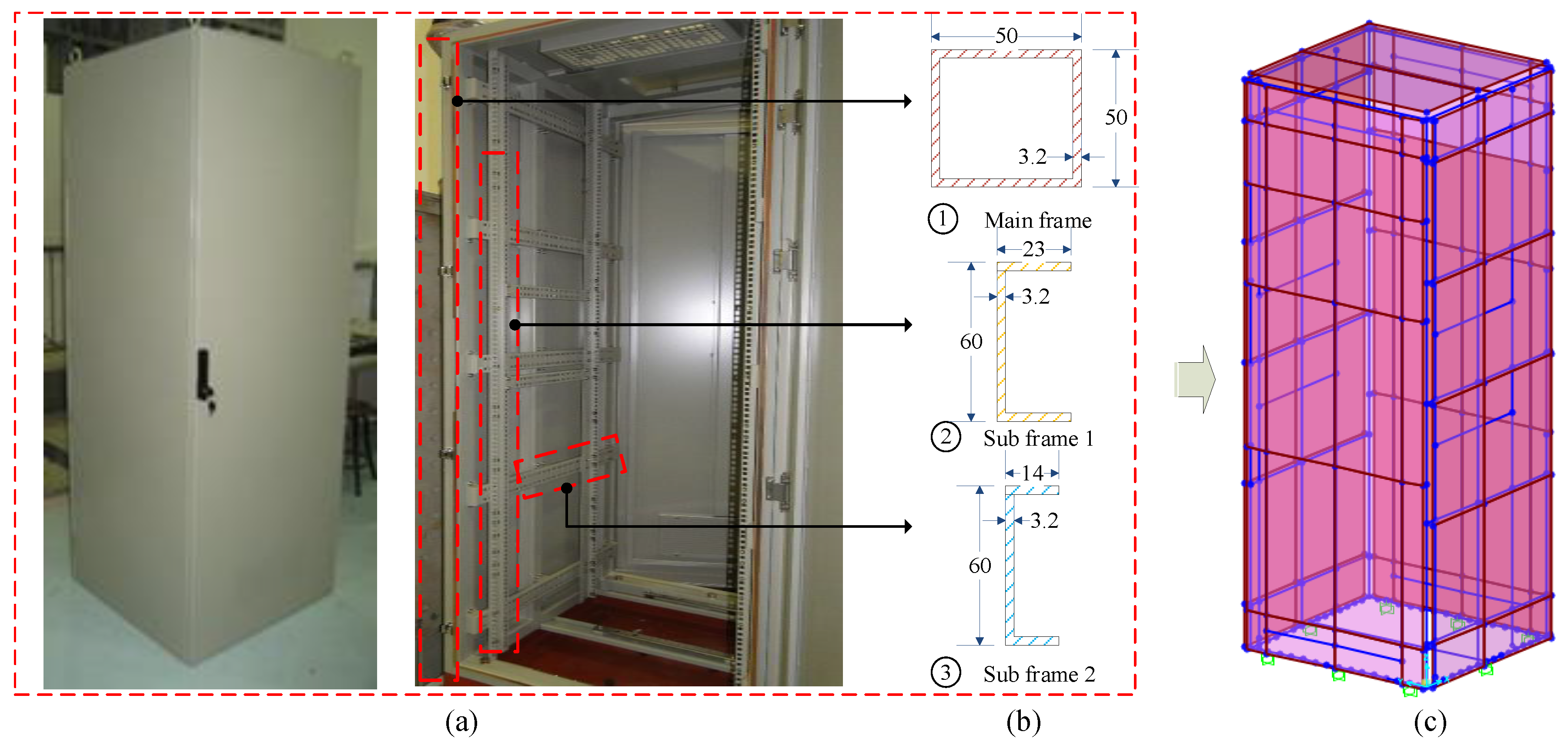
Figure 1. Test structure: (a) configuration; (b) main cross-sections (mm); and (c) finite element model.
Applsci 10 04850 g001
Figure 2. Impact hammer test: (a) Impact force; (b) sensor locations.
Applsci 10 04850 g002
Figure 3. Natural frequencies of the cabinet from the test: (a) Front-to-back; (b) side-to-side
Applsci 10 04850 g003
Figure 4. Acceleration responses at cabinet top: (a) Front-to-back; (b) side-to-side.
Applsci 10 04850 g004
Figure 5. First three mode shapes of the cabinet: (a) Mode 1 ( f = 14.43 H z ,   MPMR = 1.09 % ) ; (b) Mode 2 ( f = 14.56 H z ,   MPMR = 17.63 % ) ; (c) Mode 3 ( f = 15.13 H z ,   MPMR = 68.00 % ) .
Applsci 10 04850 g005
Figure 6. Schematic diagram of a tuned mass damper (TMD) attached to the cabinet.
Applsci 10 04850 g006
Figure 7. Finite element model of the cabinet with TMD.
Applsci 10 04850 g007
Figure 8. Response spectra (5% viscous damping) of selected ground motions: (a) High-frequency motions; (b) low-frequency motions.
Applsci 10 04850 g008
Figure 9. Electric cabinet’s performance under Pohang earthquake: (a) Acceleration response; (b) response spectra.
Applsci 10 04850 g009
Figure 10. Electric cabinet’s performance under Impevall earthquake: (a) Acceleration response; (b) response spectra.
Applsci 10 04850 g010
Figure 11. Maximum acceleration responses: (a) High-frequency; (b) low-frequency.
Applsci 10 04850 g011
Figure 12. Spectral acceleration responses (5% viscous damping) at the top of the cabinet (without TMD): (a) High-frequency; (b) low-frequency.
Applsci 10 04850 g012
Figure 13. Spectral acceleration responses (5% viscous damping) at the top of the cabinet (with TMD): (a) High-frequency; (b) low-frequency.
Applsci 10 04850 g013
Figure 14. Probability of exceedance of the acceleration responses of the cabinet from the collapse threshold: (a) HF; (b) LF earthquakes.
Applsci 10 04850 g014
Figure 15. Probability of exceedance of the acceleration responses of the cabinet from the collapse threshold: (a) without TMD; (b) with TMD.
Applsci 10 04850 g015
Table 1. Parameters of the TMD.
ParametersUnitValue
Masskg10
Mass ratio0.099
Frequency ratio0.910
Damping ratio%0.184
StiffnessN/m74.899
Table 2. AFF of the cabinet for different cases.
Casewo TMDw TMD
HFLFHFLF
AFF3.841.362.070.74
Table 3. Parameters of fragility functions.
θβ
HFLFHFLF
Wo0.5211.6990.5000.746
W0.9322.8330.4030.592