Abstract
Energy conservation and emission reduction of construction machinery are the focus of current research. The traditional excavator, whose hydraulic pump is driven by the engine, has high fuel consumption and emissions. Furthermore, it is difficult to match the working point of the engine to that of the hydraulic pump. Current pure electric drive technology has the advantages of zero pollution and low noise, and the motor used has the advantages of fast response and a wide speed range. Based on the characteristics of the pure electric drive technology, a positive flow system based on variable speed constant displacement instead of a variable displacement pump for pure electric construction machinery is put forward to realize the flow-matching of the whole machine. The basic structure and working principle were introduced. The control process was analyzed. The controllability and energy saving of the proposed system were tested through simulation and experimental analysis. The research results showed that the controllability of the proposed positive flow system was comparable to that of the traditional throttling speed-regulating control system. The energy-saving efficiency of the proposed positive flow system is increased by 35.2% compared to that of the tradition control system. To further exploit the strong overload capacity of electric motors of electric construction machinery and solve the insufficient power under sudden load, research on constant power control will be carried out in the future.
1. Introduction
Construction machinery consumes much energy and has great significance to energy conservation and emissions reduction. Various energy-saving forms have been proposed, such as hybrid power technology, which can improve fuel efficiency to some extent, but still depend on the engine [1]. There are some problems with the engine, such as low energy conversion rate, large noise, high vibration, and bad pollution discharge. With the development of power electronics technology, frequency control technology, and battery-based energy storage technology, pure electric drive technology is now widely used. The application of pure electric drive technology in construction machinery can reduce the emissions and noise, which are the shortcomings of traditional diesel and hybrid motors. Pure electric drive technology has the following advantages: (1) Electric energy, which is clean and efficient, is used. It can truly achieve zero emissions and operate pollution-free, and can meet the goal of energy conservation, emissions reduction, and sustainable development [2]. (2) The motor is used as the power source, which can improve the energy conversion rate of the power source. (3) The motor has good speed regulation, which can help to realize the power matching of the system, reducing energy loss and improving the controllability and energy-saving [3,4]. (4) The motor has good short-term overload capacity and can be applied to large burst load conditions.
To improve the energy utilization of the construction machinery, many research institutions and scholars have devoted themselves to studying the energy conservation of hydraulic systems. Some technologies, such as the negative flow control system [5,6], positive flow system (PFS) [7,8], load sensitive control system [9,10], and load port independent control system [11,12] have been successively proposed and developed. Their purpose is to reduce overflow loss and throttling loss of the system through flow matching to improve the energy utilization. PFS has no bypass oil return and no oil return loss. Furthermore, there is no pressure compensator, which can add throttling loss. Compared with other hydraulic energy saving technologies, PFS can reach the best energy saving effect. However, in a PFS, when the actuator needs to work, it takes the pump a long time to set up pressure to overcome the load [13]. Lin et al. studied the automatic idle control characteristics of a hydraulic excavator based on a PFS driven by pure electricity, but they did not discuss the characteristics of the PFS [14]. Bender et al. introduced a predictive operator modeling of a virtual prototype of a hydraulic excavator using a PFS and analyzed the influence of different driver factors on the working cycle time and capacity consumption, but they did not investigate the performance of the PFS [15]. Han put forward an energy-saving technology of a fully controlled positive flow excavator, and analyzed the energy saving property of the system. A variable pump was used in the proposed system [16]. At present, the research on the PFS of construction machinery is mainly focused on the variable pump driven by the engine, and there is less research on quantitative pumps driven by the variable speed control of the motor, which has excellent speed regulation performance. Using motor frequency control to substitute the engine is dependent on the performance of both the motor and quantitative pump. To achieve as high energy savings as possible, optimization of the hydraulic system and parameter matching between the pump and the motor should be carried out.
The frequency control technology is adapted to the hydraulic excavator by adjusting the motor speed to achieve flow matching between the hydraulic pump and the load. A PFS based on variable speed control is proposed through optimizing the parameters of the hydraulic system and the motor. Simulation and experimental analysis are used to verify the feasibility and efficiency of the proposed PFS based on variable speed. The remainder of this paper is organized as followings: Section 2 briefly introduces the structure scheme and working principle of the proposed PFS based on motor variable speed control. The control rules and control strategies of the PFS are introduced in Section 3. The controllability and energy-saving performance of the proposed system are analyzed in Section 4 and Section 5 by simulation and experiment. Conclusions are given in Section 6.
2. Structure and Principle
To further improve the energy saving and controllability of hydraulic excavators, a PFS based on variable speed control for pure electric excavators is proposed, as shown in Figure 1. The power of the motor is supplied by the power network, which minimally increases the installation cost, but can reduce the use cost to the user. In the proposed PFS, the output flow of the hydraulic pump is adjusted by changing the motor speed to meet the requirement of the load. Therefore, the energy saving of the hydraulic system can be realized by reducing the flow loss.
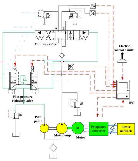
Figure 1.
Principle diagram of the positive flow system (PFS) of an electric excavator based on variable speed control.
The working process of the proposed system is as follows: when the electronic control handle receives a signal and leaves the middle position, it outputs the control signal to the motor frequency converter and to the pilot pressure-reducing valve through the controller. The multiway valve works at a certain opening according to the control signal and outputs a certain pressure and flow rate to the actuator. The sensor detects the pressure signal of the actuator and sends it to the controller. The controller outputs the control signal to the frequency converter to control the motor speed to make the output flow of the hydraulic pump match the requirement of the load. In this process, all the output flow of the hydraulic pump enters the actuator. Accordingly, the relief valve, in parallel with the main pump, which is quantitative, is used as a safety valve and there is no overflow loss. When the handle is returned to the middle position, the hydraulic pump outputs flow directly back to the tank through the multiway valve. The proposed system has the following advantages: (1) There is no overflow loss and throttling loss; therefore, the efficiency is high. (2) Due to the fast response of the motor, the pressure can be quickly established to overcome the load when the handle leaves the middle position. (3) Since the motor has high efficiency in a wide speed range, it can make the main pump have a wide range of output and adapt to different working conditions.
3. Control Strategy
Figure 2 is the control structure diagram of the PFS based on the variable speed control for a pure electric excavator. It includes the following three parts: (1) Control unit, which consists of an electronic control handle and a controller. (2) Volumetric speed regulation, which consists of a frequency converter, a motor, and a main pump. (3) Throttling speed-regulating, which includes a pilot pressure-reducing valve and a multiway valve. The controller receives the signals of the handle and the sensors to carry out the logic processing and flow forecast. According to the logic operation, the controller sends signals to the pilot valve and inverter. Accordingly, the motor speed is controlled to drive pump output at the required flow, and the pilot valve outputs pressurized oil to the multiway valve at a certain opening. Therefore, the required flow enters the actuator and flow-matching is realized.
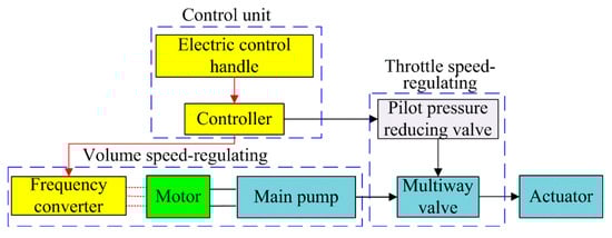
Figure 2.
Control structure diagram of a PFS based on variable speed.
According to the control structure diagram shown in Figure 2, the flow diagram of the control strategy is designed as shown in Figure 3. The controller controls the output pressure of the pilot pressure-reducing valve according to the control signal of the electronic control handle. The spool displacement of the multiway valve is controlled by the output pressure of the pilot valve. Then, the flow entering the actuator is estimated. The estimated total flow required in the actuators is:
where Qt is the total flow required in the actuator in L/min. Qn is the required flow rate of nth actuator working at the same time, n ≥ 1.
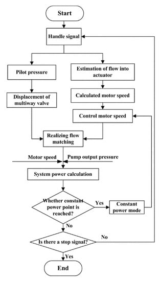
Figure 3.
Flow chart of positive flow control strategy based on variable speed control.
According to the estimated flow rate, the motor speed can be calculated as:
where nt is the target motor speed in rpm. Vp is the displacement of the quantitative pump (main pump) in mL/r. ηp is the volumetric efficiency of quantitative pump (main pump). Cs is the coefficient of the estimated speed. It is used to ensure the pump output flow has a certain margin to compensate for oil leakage.
The output power of the pump is:
where Pp is the pump output power in kW. nr is the real speed of the motor taken from the frequency converter in rpm. pp is the pump pressure in MPa.
The pump output power is compared with the constant power point. If the pump output power is less than the constant power point, a positive flow matching mode is adopted. Otherwise, the system switches to the constant power mode.
4. Simulation Results
To verify the performance of the proposed PFS based on variable speed for a pure electric excavator, the simulation model is established using AMESim, shown in Figure 4. The parameters of the key components are set in accordance with the actual actuator of a 1.5 t hydraulic excavator test rig.
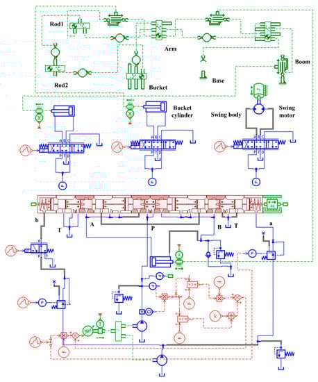
Figure 4.
Simulation model of PFS based on variable speed control.
The arm cylinder is taken as the research object. A typical cycle of the cylinder extension and recovery is studied to verify the controllability and energy-saving of the proposed PFS based on variable speed control for an electric excavator. Table 1 shows the key parameters used in the simulation. Combined with the actual parameters, the safety pressure of the relief valve in the main oil circuit is set to 20 MPa and that of the pilot oil is set to 4 MPa.

Table 1.
Simulation parameters of positive flow system (PFS) based on variable speed control.
4.1. Controllability Analysis of Proposed PFS Based on Variable Speed
Figure 5 shows the velocity and displacement curves of the arm cylinder during one cycle. It can be seen that the displacement increases to 340 mm at first and then starts to decrease, that is, the piston rod first extends and is then retracted. In this process, the maximum velocity of the piston is 0.36 m/s when it is extended and 0.33 m/s when it is retracted. The piston moves smoothly without stagnation.
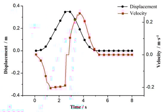
Figure 5.
Curves of velocity and displacement of the arm cylinder.
Figure 6 shows the curves of motor speed and pilot pressure. The motor speed increases with the increase of the pilot pressure and is proportional to the pilot pressure, which conforms to the operating characteristics of the PFS based on variable speed control.
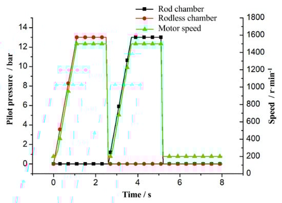
Figure 6.
Curves of motor speed and pilot pressure.
Figure 7 shows the flow rate curves of the pump and the two chambers of the arm cylinder. It shows that the flow rate output from the hydraulic pump is consistent with the flow rate into the two chambers of the arm cylinder. This indicates that flow matching is realized between the hydraulic pump and the actuator. The results verify that the proposed PFS and control strategy have good controllability.
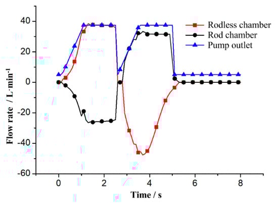
Figure 7.
Flow rate curves of the pump outlet and the two chambers of the arm cylinder.
The traditional hydraulic excavator is a fixed-speed fixed-displacement system, and the actuator speed is controlled by the throttling control. Although the throttling control system has a large energy loss, it has good controllability. Figure 8 and Figure 9 show the comparison curves of the displacement and velocity of the arm cylinder between the proposed PFS based on variable speed control and the throttling control system based on the constant speed constant displacement system. It can be seen from the curves that the displacement and velocity of the two systems are almost the same in one cycle. This indicates that the proposed PFS can achieve the same controllability as the throttling speed-regulating control system (TSCS). In the following figures, TSCS is short for throttling speed-regulating control system and PFS is short for positive flow system.

Figure 8.
Displacement curves of the arm cylinder of the two systems.
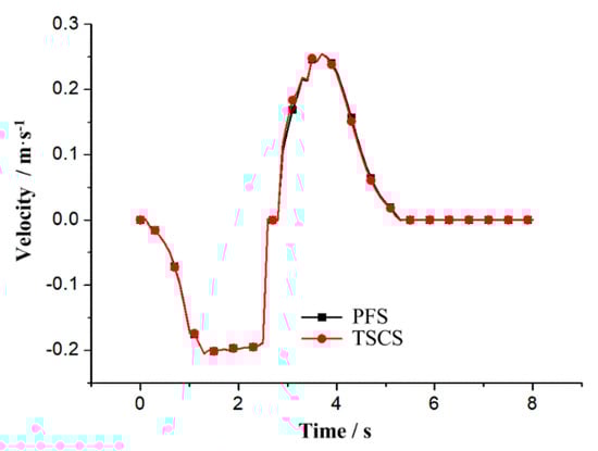
Figure 9.
Velocity curves of the arm cylinder of the two systems.
4.2. Energy Saving Analysis of Proposed PFS Based on Variable Speed
The energy consumption of a hydraulic system is mainly reflected in the power consumption, and the hydraulic power is calculated by the flow and pressure. The following is the energy consumption comparison between the PFS based on variable speed and the TSCS based on constant speed.
Figure 10 shows the pressure and flow rate curves of the main pump outlet of the two systems. As seen from the pressure curves, during the actuator’s movement, the changing trend of pump outlet pressure with the load in the two systems is basically the same. According to the flow curves, the pump output flow based on constant speed and constant displacement is almost constant, around 37 L/min. While the output flow of the PFS based on variable speed displacement is controlled by the opening of the electronic control handle, with the increasing of the handle movement amplitude, the output flow increases accordingly. Therefore, it can realize the flow matching between the pump and the load and can reduce the energy loss. This proves that the proposed PFS has good energy-saving ability.
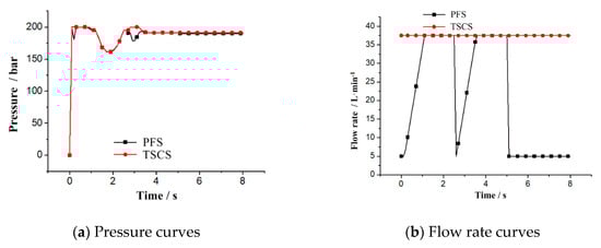
Figure 10.
Pressure and flow rate curves of the pump outlet of the two systems.
Figure 11 shows the energy consumption comparison curves of hydraulic pumps of the two systems in one working cycle. The energy consumption of PFS is lower than that of TSCS. In one working cycle, in which the arm cylinder extends and retracts, the energy consumed by TSCS is about 67.5 kJ and that of PFS is about 47.5 kJ. The energy-saving efficiency is up to 29.6%.
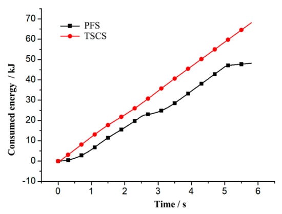
Figure 11.
Energy consumption curves of the pump in the two systems.
5. Experimental Results and Discussion
To further verify the controllability and energy saving of the proposed PFS based on variable speed control, a 1.5 t excavator test rig was built. The layout and key components of the test rig are shown in Figure 12 and Figure 13. The test rig mainly includes the following parts: (1) The variable speed power system, including the motor, main pump, and pilot pump. The dual pump is driven by the motor. (2) The throttling speed-regulating system includes a pilot proportional pressure-reducing valve and multiway valve. According to the control signal, it controls the flow into the actuator to adjust the operating speed of the actuator. (3) The measurement and control system includes an industrial PC, acquisition board, frequency converter, electric control handle, various sensors, etc. The key parameters, such as displacement and pressures, are collected and processed. Moreover, the proportional relief valve is controlled to simulate the load with the measurement and control system.
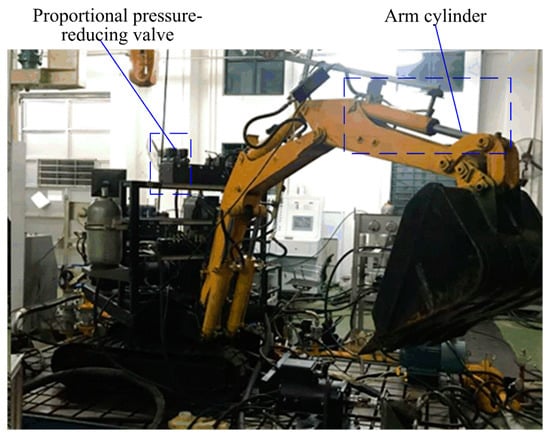
Figure 12.
A 1.5 t excavator test rig.
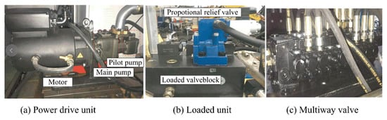
Figure 13.
Key components of the test rig.
The arm cylinder is discussed in the following test. A typical working cycle consists of the piston extending and retracting.
5.1. Controllability Analysis
Figure 14 shows the pilot pressure signal curves corresponding to the two chambers of the arm cylinder. Under the control signal of the electronic control handle, the corresponding pilot pressure-reducing valve works and outputs the pilot pressure, while the pilot pressure corresponding to the other chamber remains zero. Within 0–3.2 s, the pilot pressure-reducing valve corresponding to the rodless chamber works, and the pilot pressure increases from zero to 3.2 MPa. The cylinder completes the extension movement. Within 3.5–6.5 s, the pilot pressure corresponding to the rod chamber increases from zero to 3.2 MPa, at which time the cylinder completes the retraction movement.
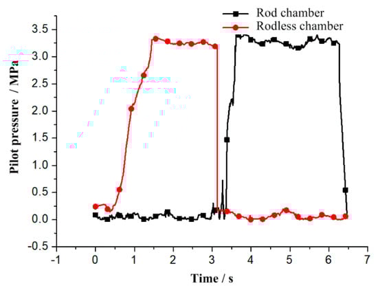
Figure 14.
Pilot pressure curves of the two chambers of the arm cylinder.
Figure 15 shows the curves of the pilot pressure and motor speed. The motor speed and the pilot pressure are both controlled by the electronic control handle signals at the same time. When the pilot pressure increases, the motor speed increases accordingly, which is conforms with the operation characteristics of the PFS based on variable speed. The motor speed rises rapidly, and there is no speed drop, except the motor speed fluctuates slightly at the maximum speed. This indicates that the output flow of the hydraulic pump can meet the requirements of the actuator for rapid movement. It also verifies that the proposed PFS based on variable speed has good controllability.
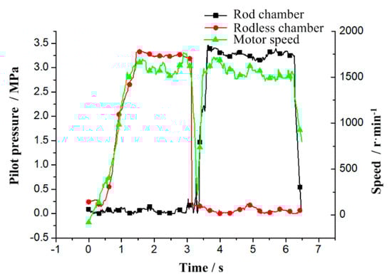
Figure 15.
Pilot pressure and motor speed curves of the PFS based on variable speed control.
5.2. Energy Saving Analysis
Figure 16 shows the pump power comparison of the PFS based on variable speed and the TSCS based on fix speed fixed displacement. It is obvious that the PFS consumes less energy than the TSCS during the working process. The maximum instantaneous power reduction is up to 3 kW.
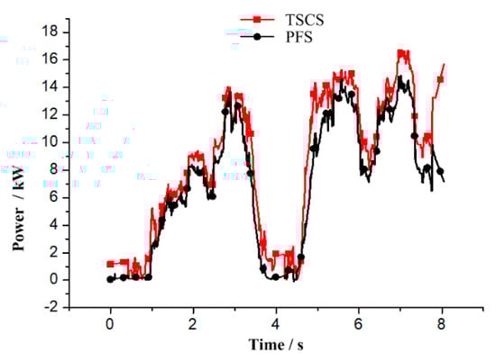
Figure 16.
Pump output power curves of the two systems.
Figure 17 shows the comparison of the pump energy consumption of the two systems. The consumed energy of the FPS is lower than that of the TSCS. During one working cycle of arm cylinder extension and retraction, the consumed energy by TSCS is about 73 kJ, while that of PFS is 54 kJ. The energy-saving efficiency of the proposed PFS can reach 35.2%. The reported energy-saving efficiency of the PFS is about 20% [17]. The experimental results prove that the proposed PFS based on variable speed has good energy-saving ability.
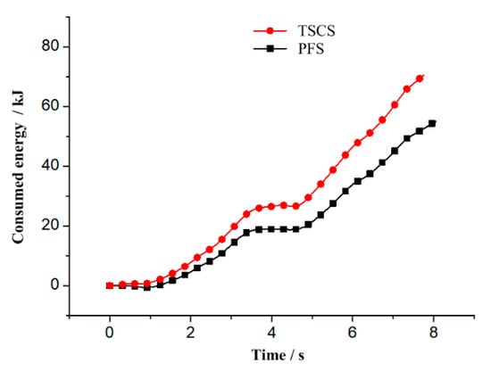
Figure 17.
Consumed energy curves of the two systems.
6. Conclusions
Pure electric construction machinery uses a motor to drive a hydraulic pump. Considering the good speed regulation performance and quick response of the motor, a PFS based on variable speed constant displacement for pure electric construction machinery is put forward to improve energy utilization and is verified by simulation and experiment. The results show that the proposed PFS based on variable speed can achieve the same controllability as a TSCS. The proposed PFS can use up to 35.2% less energy and has good energy savings compared to that of the traditional system. In addition, the cost of the hydraulic system is reduced and the volumetric efficiency of the hydraulic pump is improved because a quantitative pump is adopted. The use cost is also reduced because of the cheaper price of electric energy than diesel. The overall energy utilization rate is improved to some extent. The proposed system is not only suitable for hydraulic excavators, but also for other construction machinery such as loaders and forklifts. To fully take advantage of the strong overload capacity of electric motors and solve the issue of insufficient power under sudden load, constant power control research based on PFS with variable speed will be carried out in the future.
Author Contributions
S.F. proposed the idea of positive flow system based on variable speed control. Z.L. developed the structure and working mode. T.L. wrote the paper. Q.C. checked and edited the paper. H.R. analyzed the data. All authors have read and agreed to the published version of the manuscript.
Funding
This research was funded by National Natural Science Foundation of China (No. 51875218 & 51905180), Excellent Outstanding Youth Foundation of Fujian Province (No. 2018J06014), Industry Cooperation of Major Science and Technology Project of Fujian Province (No. 2019H6015), Natural Science Foundation of Fujian Province (No. 2018J01068 & 2019J01060), and STS project of Fujian Province (No. 2018T3015). This work also has been supported by Fujian Southchina Heavy Machinery Manufacture Co., Ltd.
Conflicts of Interest
The authors declare no conflict of interest.
Nomenclature
| Cs | coefficient of the estimated speed |
| nc | target motor speed |
| nr | real speed of the motor taken from the frequency converter |
| pp | pump pressure |
| Pp | pump output power |
| Qn | required flow rate of nth actuator working at the same time |
| Qt | total flow required in the actuator |
| Vp | displacement of the quantitative pump (main pump) |
| ηp | volumetric efficiency of quantitative pump (main pump) |
Abbreviations
| PFS | positive flow system |
| TSCS | throttling speed-regulating control system |
References
- Lin, T.; Wang, Q.; Hu, B.; Gong, W. Development of hybrid powered hydraulic construction machinery. Autom. Constr. 2010, 19, 11–19. [Google Scholar] [CrossRef]
- Fu, S.; Chen, H.; Ren, H.; Tian, L.; Miao, C.; Chen, Q. Potential Energy Recovery System for Electric Heavy Forklift Based on Double Hydraulic Motor-Generators. Appl. Sci. 2020, 10, 3996. [Google Scholar] [CrossRef]
- Ren, H.; Lin, T.; Zhou, S.; Huang, W.; Miao, C. Novel Automatic Idle Speed Control System with Hydraulic Accumulator and Control Strategy for Construction Machinery. Appl. Sci. 2018, 8, 496. [Google Scholar] [CrossRef]
- Fu, S.; Wang, L.; Lin, T. Control of electric drive powertrain based on variable speed control in construction machinery. Autom. Constr. 2020, 119, 103281. [Google Scholar] [CrossRef]
- Yang, Y.; Wu, W.; Deng, B. Study on Energy Saving of Hydraulic Excavator Based on Negative Flow Control. Mach. Tool Hydraul. 2013, 23, 125–127. [Google Scholar] [CrossRef]
- Cadman, K. Electro-Hydraulic System with Negative Flow Control. U.S. Patent Application 20180087540, 26 November 2018. [Google Scholar]
- Zhang, J.; Li, K.; Guan, L.; Zhu, T. Research on Positive Control System with Synthetic Pilot Pressure of Excavator. China Mech. Eng. 2012, 23, 1536–1541. [Google Scholar] [CrossRef]
- Bedotti, A.; Pastori, M.; Casoli, P. Modelling and energy comparison of system layouts for a hydraulic excavator. Energ. Procedia 2018, 148, 26–33. [Google Scholar] [CrossRef]
- Cheng, M.; Zhang, J.; Xu, B.; Ding, R. An Electrohydraulic Load Sensing System based on flow/pressure switched control for mobile machinery. ISA Trans. 2019, 96, 367–375. [Google Scholar] [CrossRef] [PubMed]
- Sugimura, K.; Murrenhoff, H. Hybrid Load Sensing—Displacement Controlled Archtecture for Excavators. In Proceedings of the 14th Scandinavian International Conference on Fluid Power, Tampere, Finland, 20–22 May 2015. [Google Scholar]
- Shi, J.; Quan, L.; Zhang, X.; Xiong, X. Electro-hydraulic velocity and position control based on independent metering valve control in mobile construction equipment. Autom. Constr. 2018, 94, 73–84. [Google Scholar] [CrossRef]
- Zhong, Q.; Zhang, B.; Bao, H.; Hong, H.; Ma, J.; Ren, Y.; Yang, H.; Fung, R. Analysis of pressure and flow compound control characteristics of an independent metering hydraulic system based on a two-level fuzzy controller. J. Zhejiang Univ.-Sci. 2019, 20, 184–200. [Google Scholar] [CrossRef]
- Wang, S.; Li, Z.; Yu, X. Energy saving analysis and realization of the inverted flux control system of hydraulic excavators. J. Hefei Univ. Technol. (Nat. Sci.) 2006, 29, 213–216. [Google Scholar] [CrossRef]
- Lin, T.; Wang, L.; Huang, W.; Ren, H.; Fu, S.; Chen, Q. Performance analysis of an automatic idle speed control system with a hydraulic accumulator for pure electric construction machinery. Autom. Constr. 2017, 84, 184–194. [Google Scholar] [CrossRef]
- Bender, F.; Mitschke, M.; Bräunl, T.; Sawodny, O. Predictive operator modeling for virtual prototyping of hydraulic excavators. Autom. Constr. 2017, 84, 133–145. [Google Scholar] [CrossRef]
- Han, S. Research on Energy Saving Technology of Total Electronic Positive Flow Control Excavator. Master’s Thesis, Jilin University, Jilin, China, 2017. [Google Scholar]
- Liu, J.; Zhang, E. Control system simulation analysis of hydraulic excavator positive flow. Constr. Mach. 2014, 4, 97–104. [Google Scholar] [CrossRef]
© 2020 by the authors. Licensee MDPI, Basel, Switzerland. This article is an open access article distributed under the terms and conditions of the Creative Commons Attribution (CC BY) license (http://creativecommons.org/licenses/by/4.0/).