Article

Vibration Characteristics of Rolling Element Bearings with Different Radial Clearances for Condition Monitoring of Wind Turbine

1
State Key Laboratory of Mechanical Transmission, Chongqing University, Chongqing 400044, China
2
Centre for Efficiency and Performance Engineering, University of Huddersfield, Huddersfield HD1 3DH, UK
3
State Key Laboratory of Mechanical System and Vibration, Shanghai Jiao Tong University, Shanghai 200240, China
*
Author to whom correspondence should be addressed.
Appl. Sci. 2020, 10(14), 4731; https://doi.org/10.3390/app10144731
Submission received: 16 May 2020 / Revised: 27 June 2020 / Accepted: 3 July 2020 / Published: 9 July 2020
(This article belongs to the Special Issue Wind Power Technologies)

Abstract

:
Rolling element bearing is a vital component in rotating machinery, such as a wind turbine (WT) system. By accurately monitoring its health condition, the faults can be detected at an early stage, providing sufficient lead time to perform maintenance and hence reducing accidents and economic losses. Bearing usually suffers from various wears and tears, which result in a gradual increase in clearance through its lifetime. Insufficient understanding of vibration characteristics under different clearances brings difficulties for bearing condition monitoring. Thus, this paper presents a nonlinear bearing vibration model with six degrees of freedom (DOF) to investigate the vibration characteristics under different radial clearances and load conditions. Then, a dedicated bearing test is established to verify the reasonability and effectiveness of the vibration model. Furthermore, a comprehensive simulation analysis is conducted to study the vibration characteristics over an extended range of the internal radial clearance and external load. Results show that the dynamic force on each ball presents an impulse whose magnitudes increases whereas the pulse width reduces with clearance increases. Ball pass frequency of outer race (BPFO) is the dominant modulation component and the frequency is in accordance with the number of dynamic force impulses. Two indicators, i.e., root mean square (RMS) value and spectral centroid, are proposed to indicate clearance changes. In general, they show an uptrend with the increase in clearance, which is in line with the dynamic force increasing with clearance, especially the spectral centroid of the low frequency band. However, it should be noted that the RMS value and spectral centroid exhibit a fluctuating behavior due to nonlinear vibration responses. For the first time, this study shows the details of vibration characteristics with clearance variations and provides a foundation for monitoring the bearing conditions before any obvious local defects on raceways.

1. Introduction

Wind energy, as a kind of renewable and clean energy resource, has become the fastest-growing energy source [1]. Wind farms capture the wind flow through wind turbines (WT), which can convert the wind energy into electricity by rotating blades around a rotor. In the WT systems, regardless of on the main shaft or in the gearbox or the generator, rolling element bearings are critical mechanical components to support the shaft or the rotor [2]. Complex working conditions, such as time-varying rotating speed, nonstable load and harsh environments, challenge the reliability of WT units. This could easily lead to wear and tear on bearings, resulting in faults or even fatal breakdowns, causing catastrophic accident and economic losses [3,4]. Investigation has shown that more than 50% of faults on gearboxes were caused by bearings [5]. Together with the various types and certain amounts, bearing faults bring difficulties to the maintenance of WT units. With the wide installation of wind turbines worldwide, the accurate condition monitoring of rolling element bearing has attracted considerable attention in recent years.
Once a local bearing defect appears, it induces an impulse excitation to the system, which will excite resonant frequencies of the bearing and its adjacent components [6]. Thus, vibration signal is widely used in bearing fault diagnosis. A large volume of works has purely relied on the vibrational signals for fault detection and classification without consideration of the failure mechanisms lying behind. These methods are usually categorized as data-driven methods and many such methods have been developed [7,8,9]. However, these data-driven methods require a good knowledge of mechanical structure and vibration mechanism. On the other hand, it is the foundation of mechanical fault diagnosis to find out the mechanism and representation form of the fault [10,11]. Through model-based analysis, dynamic characteristics of the system could be obtained. McFadden [12] developed a model to describe the vibrations produced in a rolling element bearing under constant radial loads with a single point defect on the inner race. Liu et al. [13] proposed a new model taking time-varying contact stiffness into consideration, to reveal the relationship between vibration characteristics and defect sizes.
Comparatively, few scholars have focused on the vibration characteristics and health monitoring of bearings before obvious local defects appearing on raceways. In a WT system, unsteady wind and gusts will lead to high contact stresses on rolling elements and bearing skidding. Wear is the main cause of bearing failures [14]. Especially, abrasive wear seems to be the most common wear type observed in bearings in the industry [15]. Investigation has shown that wear and tear can shorten bearing life by about 30% [16]. However, during the lifetime of bearings, the wear process is different from surface roughness, and it is difficult to measure wear loss, which needs special equipment and methods [17]. Meanwhile, investigations show that wear and tear during the bearing operating process give rise to clearance [18]. In addition, the internal radial clearance affects the load distribution, and consequently influences the fatigue life of rolling bearings [19,20]. In view of structural vibrations also highly influencing the propagation of wear [15], significant efforts need to be dedicated to study the vibration characteristics under different bearing clearances before obvious local defects appearing, which could provide more guidance for bearing condition monitoring.
Tribology-focused techniques provide meaningful exploration for bearing fault diagnosis and condition monitoring. Halme and Andersson [18] expounded the connections between bearing diagnosis and tribology mechanisms, pointing out that rolling contact wear and fatigue during rolling bearing operations can be diagnosed by combining measured and interpreted condition monitoring data. Ocak et al. [21] proposed a method for bearing prognostics with wavelet packet decomposition and probabilistic modelling to realize the online tracking of bearing wear. Rehab et al. [22] investigated the impact of wear induced clearances on diagnostic characteristics, which confirmed the general understanding of increased amplitudes with clearance for the inner and outer race defects. Note that these efforts still focus on improving the performance of diagnosing local defects and few studies have been found to analyze the continuous changes in bearing clearance without local defects.
To monitor the bearing clearances, Zmarzły [23] assessed the influence of the bearing radial clearance on vibration level by experiments and pointed out that medium vibration frequency band (300–1800 Hz) has the biggest impact. Georgiadis et al. [24] utilized spectral kurtosis to predict bearing clearance changes. Yakout et al. [19] studied the effect of the internal radial clearance on the damping characteristics and natural modes of vibration through experimental tests. Meier et al. [25] applied three different methods (kurtosis, recurrences and neural networks) for measuring the bearing clearance and found a correlation between the bearing clearance, level of bearing vibrations and output signal structure. Recently, Wang et al. [26] proposed an online bearing clearance monitoring approach based on modulation signal bispectrum (MSB) and Gini-index to diagnose the change of bearing clearance without local defects. Although there are some indicators utilized to monitor the change of bearing clearance of certain levels through experiments, it should be noted that the mechanism behind bearing clearance is not revealed and remains ambiguous, whereas it is the basis of accounting for various vibration phenomena and bearing condition monitoring.
Overall, although a few studies have begun to focus on bearing clearances and paved the foundations for this study, several problems existed in these studies, such as a lack of mechanism research, incomplete vibration characteristics and insufficient reasonable monitoring indicators. These deficiencies bring difficulties to bearing condition monitoring and maintenance of WT systems. On the other hand, accurate monitoring of the bearing clearance before obvious local defect could provide sufficient lead time to perform maintenance and hence reduce accidents and economic losses. Thus, it is a meaningful exploration to study bearing clearances.
In this paper, to bridge the gap, a nonlinear bearing vibration model is proposed to investigate the vibration characteristics for bearing condition monitoring under different internal clearances, as well as external loads. Firstly, a six degree of freedom (DOF) bearing dynamic model, which includes nonlinearity of radial clearance, is established based on structural mechanism analysis and Hertz contact theory. Then, experimental tests are carried out to verify the rationality of the model based on the comparison between simulation and test data. Finally, dynamic force, vibration characteristics and monitoring indicators are expounded at a wider range of radial clearance, load and rotational speed. The main contribution of this paper lies in the non-linear vibration model and the influence of continuously changing clearances on dynamic force and vibration characteristics.

2. Numerical Modelling

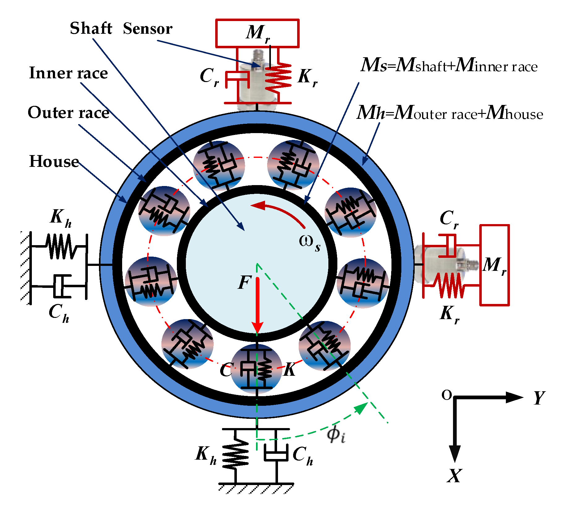
2.1. Bearing Vibration Model Considering Clearance

To study the dynamic behaviors of bearings, a large number of works have focused on bearing models for bearing vibration characteristics or diagnostic signatures. Sunnersjo [27] first proposed a two-DOF mathematical bearing vibrations model based on Hertz contact theory. Arslan et al. [28] considered the shaft-bearing assembly as a mass-spring system to investigate the nonlinear characteristic of rolling element vibrations. Sawalhi and Randall [29] studied the influence of pedestal and proposed a five-DOF bearing-pedestal model to simulate localized bearing faults. Xiao et al. [30] investigated the vibration transmission characteristics through a dynamic model of the gear-shaft-bearing-housing system. Liu and Shao [31] took housing and shaft into consideration and proposed a lumped spring mass model for a ball bearing system to study the localized defect sizes on the vibration characteristics. Through these literatures, the shaft-bearing-housing model has better performance when describing bearing vibrations, and it is widely used in bearing studies.
Thus, in this study, a lumped shaft-housing vibration model is developed with six DOF, which includes two sensors, as shown in Figure 1. In this shaft-housing system, M s includes the mass of inner race and shaft and M h includes the mass of outer race and house, which is a common configuration of bearing operations. Moreover, it allows the numerical simulations to be evaluated by corresponding experiments. In this system, X s , Y s , X h , Y h , X r and Y r represent the displacement of the shaft (s), housing (h) and sensor (r) in the X and Y directions, respectively. X ˙ and X ¨ denote velocity and acceleration, respectively.
The bearing vibration model is presented in Equations (1)–(6).
M s X s ¨ + i = 1 N b K [ δ i ] 3 / 2 c o s ϕ i + i = 1 N b C [ v i ] c o s ϕ i = F ,
M s Y s ¨ + i = 1 N b K [ δ i ] 3 / 2 s i n ϕ i + i = 1 N b C [ v i ] s i n ϕ i = 0 ,
M h X h ¨ + C h X h ˙ + K h X h i = 1 N b K [ δ i ] 3 / 2 c o s ϕ i i = 1 N b C [ v i ] c o s ϕ i = 0 ,
M h Y h ¨ + C h Y h ˙ + K h Y h i = 1 N b K [ δ i ] 3 / 2 s i n ϕ i i = 1 N b C [ v i ] s i n ϕ i = 0 ,
M r X r ¨ + C r ( X r ˙ X h ˙ ) + K r ( X r X h ) = 0 ,
M r Y r ¨ + C r ( Y r ˙ Y h ˙ ) + K r ( Y r Y h ) = 0 ,
where M s , M h and M r denote the mass of shaft, housing and sensor, respectively. In addition, K h , and K r represent the stiffness of housing and sensor; C h and C r are the damping of housing and sensor; K and C , respectively, represent the stiffness and damping between raceways and balls; δ i and v i represent the nonlinear deformation and nonlinear velocity of the i th ball, respectively; ϕ i denotes the angle position of the i th ball; and N b denotes the number of rolling elements. The deformation δ i and velocity v i for each element could be calculated by Equations (7) and (8)
δ i = { ( X s X h ) c o s ϕ i + ( Y s Y h ) s i n ϕ i c / 2 × ( 1 c o s ϕ i ) δ i > 0 , 0 δ i 0 ,
v i = { ( X s ˙ X h ˙ ) c o s ϕ i + ( X s ˙ X h ˙ ) s i n ϕ i δ i > 0 , 0 δ i 0 .
where c denotes radial clearance.
According to Hertz contact theory [19,22], the total stiffness between two raceways can be expressed as the sum of the corresponding stiffness between the rolling elements and each raceway, given as
K = [ 1 ( 1 / K i ) 1 / ( 3 / 2 ) + ( 1 / K o ) 1 / ( 3 / 2 ) ] 3 / 2
where K i , o is the Hertz contact stiffness between the outer and inner raceways with the ball, respectively.
K i , o = 2 2 ( E 1 ν 2 ) 3 ( ρ ) 1 / 2 ( 1 δ * ) 3 / 2
where E is Young’s modulus, ν is Poisson’s ratio, ρ is the curvature sum and δ * is the dimensionless contact deflection.
The equivalent viscus damping coefficient between two raceways can be calculated according to Equation (11) at a given damping ratio.
C = 2 ς m b × K
where ς is the damping ratio, m b is the mass of each ball.

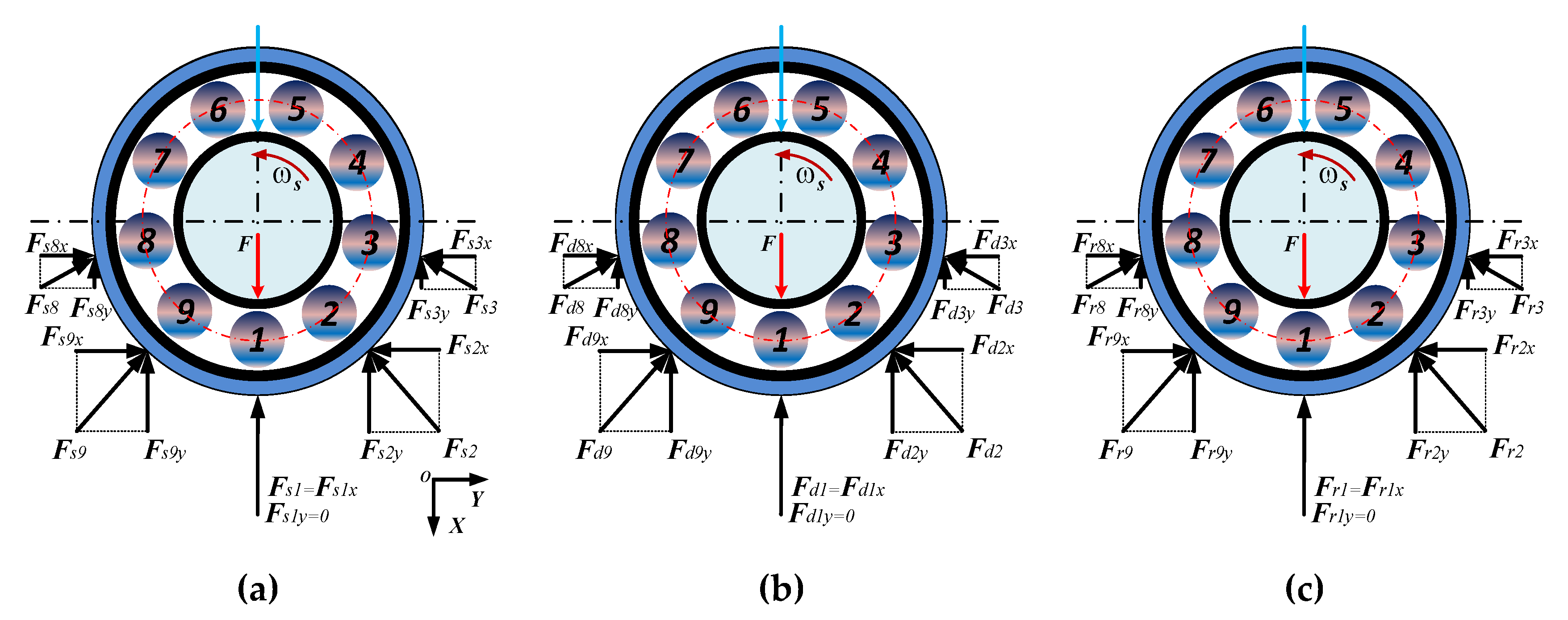
2.2. Dynamic Force Model

Based on the fact that there is a direct relationship between force and vibration, dynamic forces are extracted from the numerical simulation. It can be seen in the bearing vibration model that the nonlinear dynamic forces are
F s i x = K [ δ i ] 3 / 2 c o s ϕ i ;   F s i y = K [ δ i ] 3 / 2 s i n ϕ i ;
F d i x = C [ v i ] c o s ϕ i ;   F d i y = C [ v i ] s i n ϕ i ;
where F s i x and F s i y represent the spring force in the X direction and Y direction of the i th ball, respectively; F d i x and F d i y denote the damping force in the X direction and Y direction of the i th ball, respectively.
The schematic diagram of the dynamic force is shown in Figure 2. The resultant forces can be calculated according to Equations (14) and (15).
F r i x = F s i x + F d i x ;   F r i y = F s i y + F d i y ;
F r x = i = 1 N b F r i x ;   F r y = i = 1 N b F r i y ;   F r = ( F r x ) 2 + ( F r y ) 2
where F r i x and F r i y represent the resultant force of the i th ball in the X direction and Y direction of the i th ball; F r x and F r y denote the resultant force in the X direction and Y direction of all the balls, respectively; F r denotes the sum of forces on all balls. It is noted that the X and Y directions represent direction with and without external load, respectively, named load and non-load direction in the following text of this study.

2.3. Numerical Simulation Implementation and Analysis

To concentrate the study on the influences of bearing clearance on vibration responses, the model was based on the following assumptions and considerations.
(1)
The vibration model is developed for an ideal bearing under perfect operating conditions, i.e., geometric errors and assembly errors are ignored;
(2)
The bearing operates under isothermal conditions, i.e., the influence of temperature is not considered;
(3)
The lubrication is sufficient and appropriate during the operation at a constant speed, i.e., abnormal lubrication and raceway roughness and waviness are not taken into account;
(4)
The motion between raceways and balls is regarded as pure rolling without any sliding and skidding between bearing components;
(5)
The sensor is considered as a mass-damping system.
Taking 6206 deep groove ball bearing as an example, the main geometry parameters of the adopted 6206 deep groove ball bearing are listed in Table 1. The model parameters for simulation are listed in Table 2. It was noted that the increase in clearances was realized through the variation of raceway diameter. In addition, the rotational speed of the shaft was 1500 rpm and the vibration model was iteratively solved in MATLAB 2018a with the sub-function of ode15 s.
Taking the load of 1600 N and the clearance of 10 μ m as an example, the vibration acceleration, spectrum and envelope spectrum of the sensor in load and non-load direction are shown in Figure 3. As can be seen, the waveform displayed periodic impulses and two peaked regions could be clearly distinguished from the spectrum in both directions. Through envelope analysis, it was found that the ball pass frequency of outer race (BPFO) and its harmonics dominated the entire spectrum. Coincidentally, the amplitude of the non-load direction was higher than the load direction. The higher vibration level in the non-load direction could be attributed to the more complicated motion of the bearing system and the influence of dynamic force.
Without loss of generality, dynamic force of the first ball was calculated according to Equation (15). Figure 4a,b depict the spring and damping force, respectively. In Figure 4, F s 1 x and F s 1 y represent the spring force in the load direction and non-load direction of the first ball, respectively; F d 1 x and F d 1 y denote the damping force in the load direction and non-load direction of the first ball, respectively; F s 1 , F d 1 and F r 1 denote the damping force, damping force and resultant force of the first ball, respectively; F r represents the resultant force of all balls.
As can be seen, although there was no external load in the non-load direction, due to the difference in the contact angle of each element, the force in the non-load direction fluctuated as well. The resultant dynamic force of each ball displayed a periodic impulse, as shown in Figure 4c. When sum all F r i x and F r i y , the resultant force of all balls was equal to the external load of 1600 N, with little fluctuations, as shown in Figure 4d, which also provided evidence for the accuracy of the dynamic force analysis and the model.
In addition, from Figure 4c, when the shaft rotated a full turn, there were 9 impulses, which was equal to the number of rolling elements. According to the simulation, the time of shaft rotating one cycle was 0.1002 s. Thus, in 1 s, there were about 89.8 balls passing the same point on the outer race. This is in accordance with the theoretical value of the ball pass frequency of the outer race (BPFO, 89.8 Hz).

3. Model Verification on a Bearing Test Rig

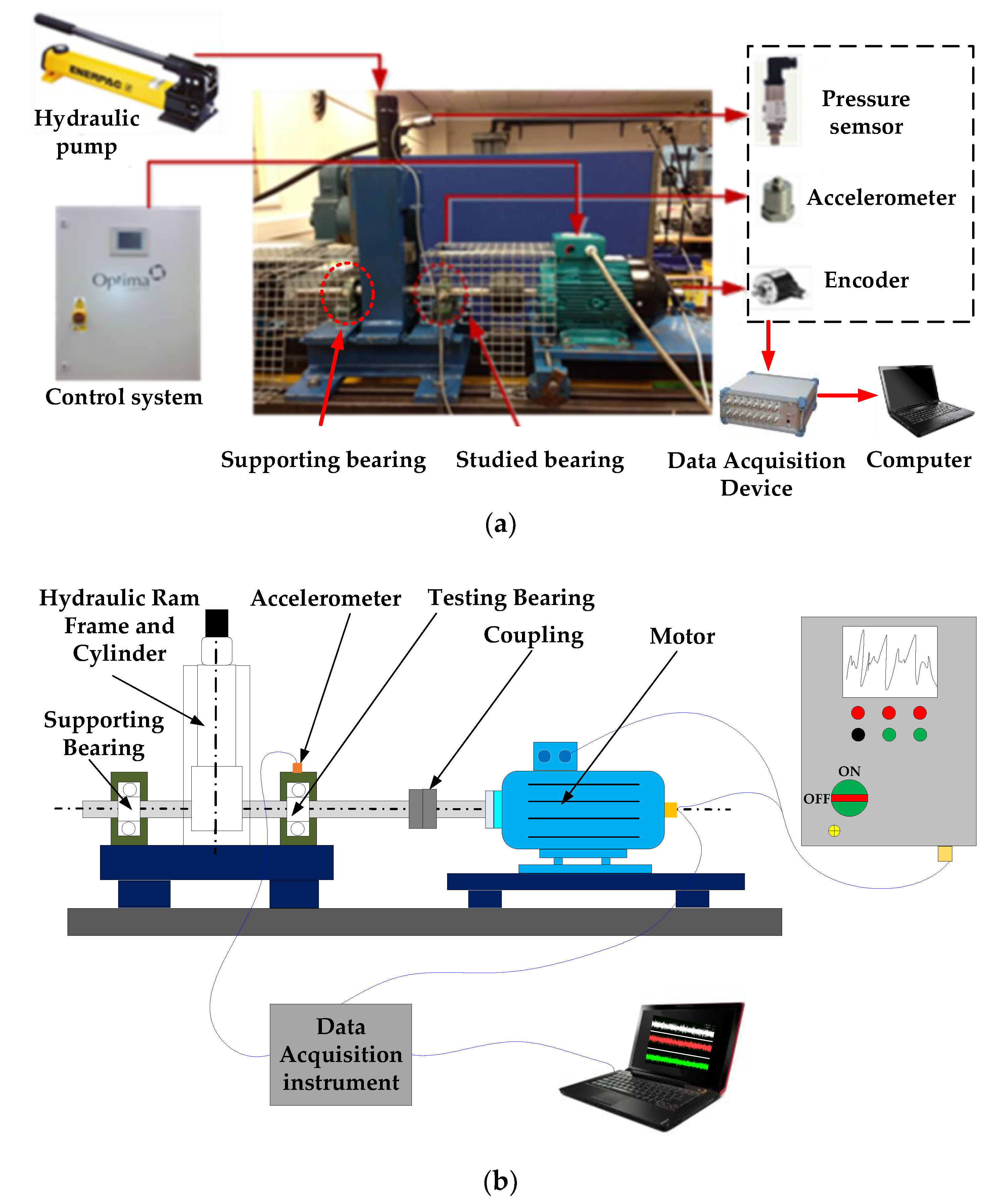
3.1. Bearing Test Rig Setup

To validate the accuracy of the dynamic model, a vibration test was carried out on a bearing test rig, which had two deep groove ball bearings to support the shaft. The type of tested bearing was 6206 ZZ, which was placed at the drive end of the shaft, as shown in Figure 5. The measurement system, such as sensors, data acquisition device, load device, motor and control unit can be found in Figure 5a. In addition, the sampling frequency was set at 96 kHz and each frame of signal was recorded for 20 s, which allowed sufficient precision to be achieved in waveform and in the spectrum analysis.
To study the influence of clearance on vibration characteristics, two groups of bearings with different clearances, named CN and C4, were tested, representing ”normal” clearance and ”large” clearance, respectively. The clearances for these two types of bearings are listed in Table 3. During the experiment, the rig ran at a shaft speed of 1500 rpm and different radial loads, namely, 0, 10, 20 and 30 bar, were applied with hydraulic equipment. With the diameter of the piston as 45 mm , the above loads, i.e., 10, 20 and 30 bar, applied on the testing bearing could be calculated as 800, 1600 and 2400 N, respectively.

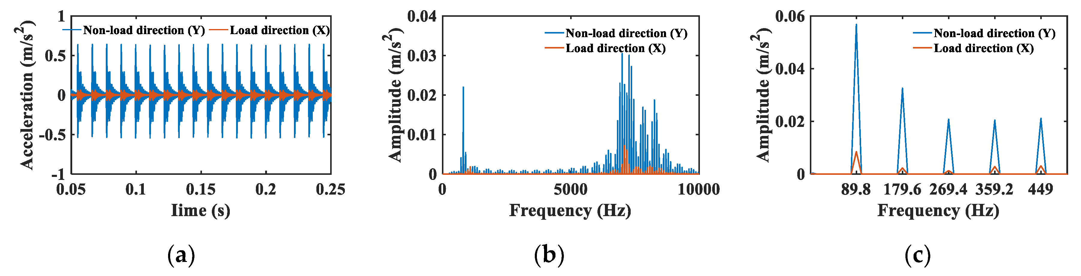
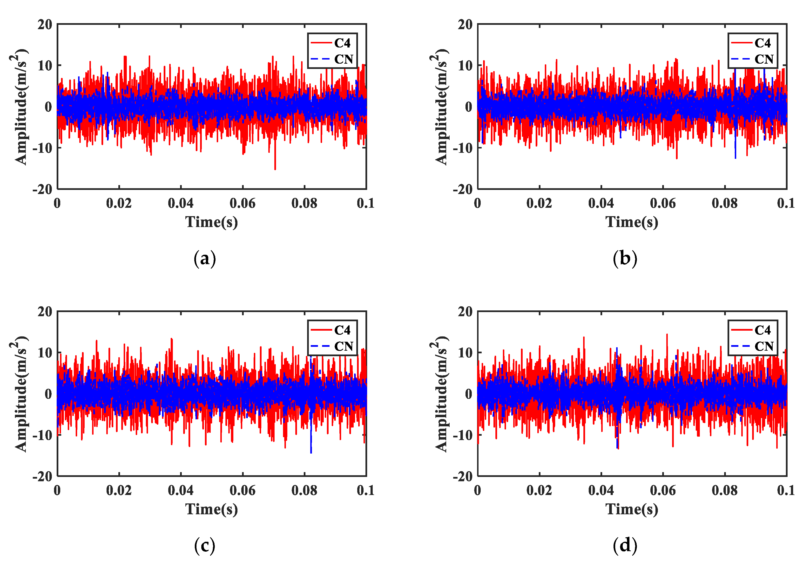
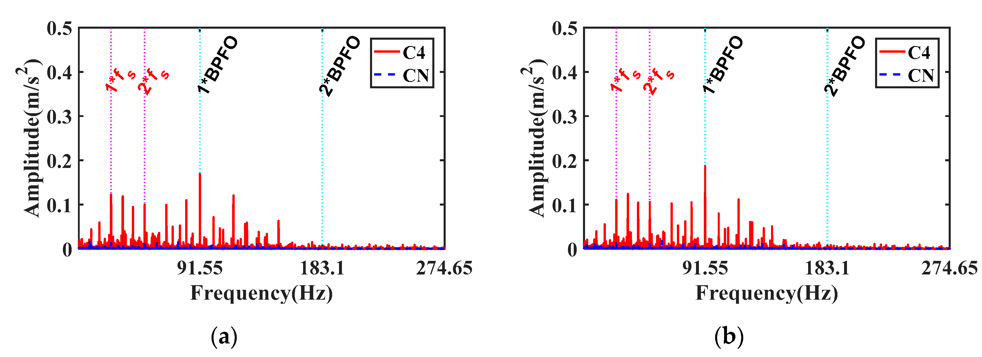
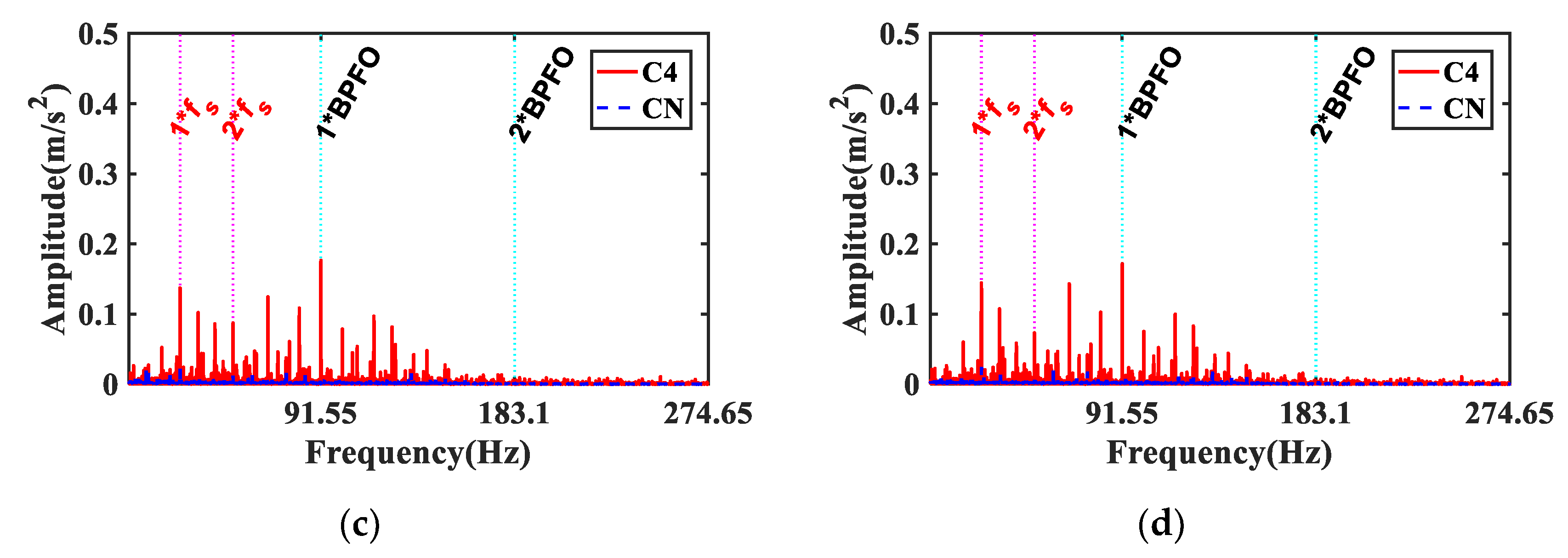
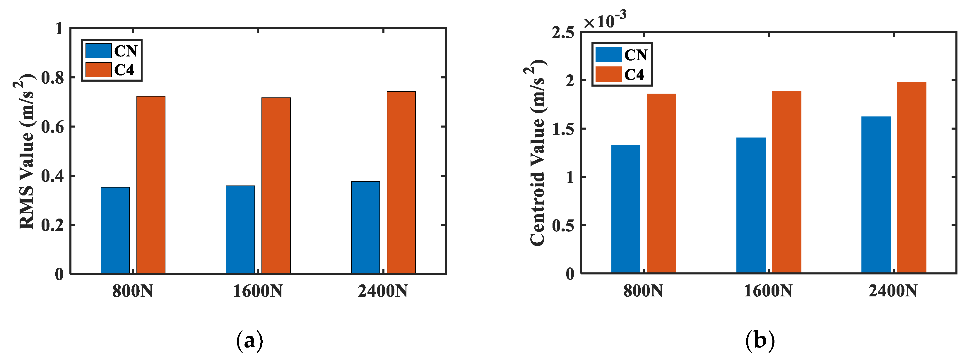
3.2. Model Verfication with Vibration Data

A comparison was made between the test and simulation in the time domain and frequency domain. According to the test, the vibration waveforms in the time domain are shown in Figure 6. As can be observed, the amplitudes of vibration signals from C4 bearing were larger than those from CN bearing. To show their differences more clearly, the root mean square (RMS) of the vibration signals was calculated and presented in Figure 7b. As expected, the RMS value of C4 was larger than that of CN. Furthermore, when under larger clearances C4, the RMS value showed an uptrend with the increase in load, which is in line with the numerical simulation in Figure 7a. However, under smaller clearance CN, the RMS value showed different trends in both the simulation and test signals. The RMS value of the simulation data showed a downtrend with loads, while that of the test data was nearly similar among different loads. The downtrend of the simulation data may be due to the influence of resonance caused by load. When under the same clearances, the bearing load distribution varied with the external load on it. When load was relatively small, there were less balls in the contact region, which may result in larger vibrations. The trend of actual measurements may be influenced by background noise or other joint components.
Except for the time domain analysis, the frequency spectra of the simulation signal and test signal were calculated and compared in Figure 8. Note that “800-10” in Figure 8a means that the load was 800 N and the clearance was 10 μ m . Such expression was adopted in the following text. From the frequency spectrum of the simulation signal, it is easy to distinguish the low frequency band and the high resonant frequency band. However, the spectrum of the test signal is quite complicated with multiple unknown resonant frequencies, which may be generated by other components in the test rig. Nevertheless, with the increase in clearance, an uptrend could be clearly observed from the spectrum of both the simulation and test signals.
It is well known that the vibration signal from a bearing with local defects shows significant modulation effects. As show in a late study, the local dynamic load can induce the modulation effect in the resonances. An envelope spectrum was thus also utilized to reveal the demodulation phenomenon. Figure 9 and Figure 10 depict the envelope spectrum of the simulation signal and test signal under different clearances and loads.
As can be seen from the envelope spectrum in Figure 9, BPFO and its harmonics dominated the entire spectrum for different clearances and load conditions. In Figure 10, the harmonics of the rotating frequency f s and BPFO can be clearly observed together, though there are a number of unresolved frequency components due to the dynamic effects of motor and coupling. Note that the amplitude of BPFO and its harmonics were much higher than other frequency components. This means that BPFO plays an important role in the modulation process for bearing with clearances. In addition, the amplitude of BPFO from bearing with a larger clearance (red solid line) was much higher than that from bearing with smaller clearances (blue dotted line). All these findings are consistent with the simulation study.
Based on these findings, it is reasonable to conclude that the proposed dynamic model is competent to describe the bearing vibration under different clearances.

4. Vibration Characteristics for Bearing Clearance Monitoring

According to the International Organization for Standardization (ISO), the clearance of deep groove ball bearing is divided into five classes, namely C2, CN (Normal), C3, C4 and C5 [19]. Table 4 depicts the maximum and minimum of these five classes of clearance under different nominal bore diameters. Note that these clearances merely showed the rated clearance of bearings after manufacturing. With bearings being put into operation, they suffer from various levels of wear and tear, which will lead to the increase in the clearance. Investigations have shown that the clearance has a vital effect on bearing useful life, and the increase in clearance will shorten the bearing service life by approximately 30% [16].
To gain a comprehensive understanding of the vibration characteristics caused by bearing clearance and load conditions, a group of simulation studies were carried out. In the simulation study, the clearances ranged from 0 to 100 μ m with the interval as 10 μ m , while the load ranged from 800 to 4800 N with the interval as 800 N. Note that the load was set according to the bearing rotating life L 10 h . When the basic rated dynamic load was 20.3 kN (bearing 6206), the rotating life under each load was about 181,541, 22,693, 6724, 2837, 1452 and 840 h, respectively. Thus, these loads could be divided into light load (800 N, 1600 N), medium load (2400 N, 3200 N) and heavy load (4000 N, 4800 N).

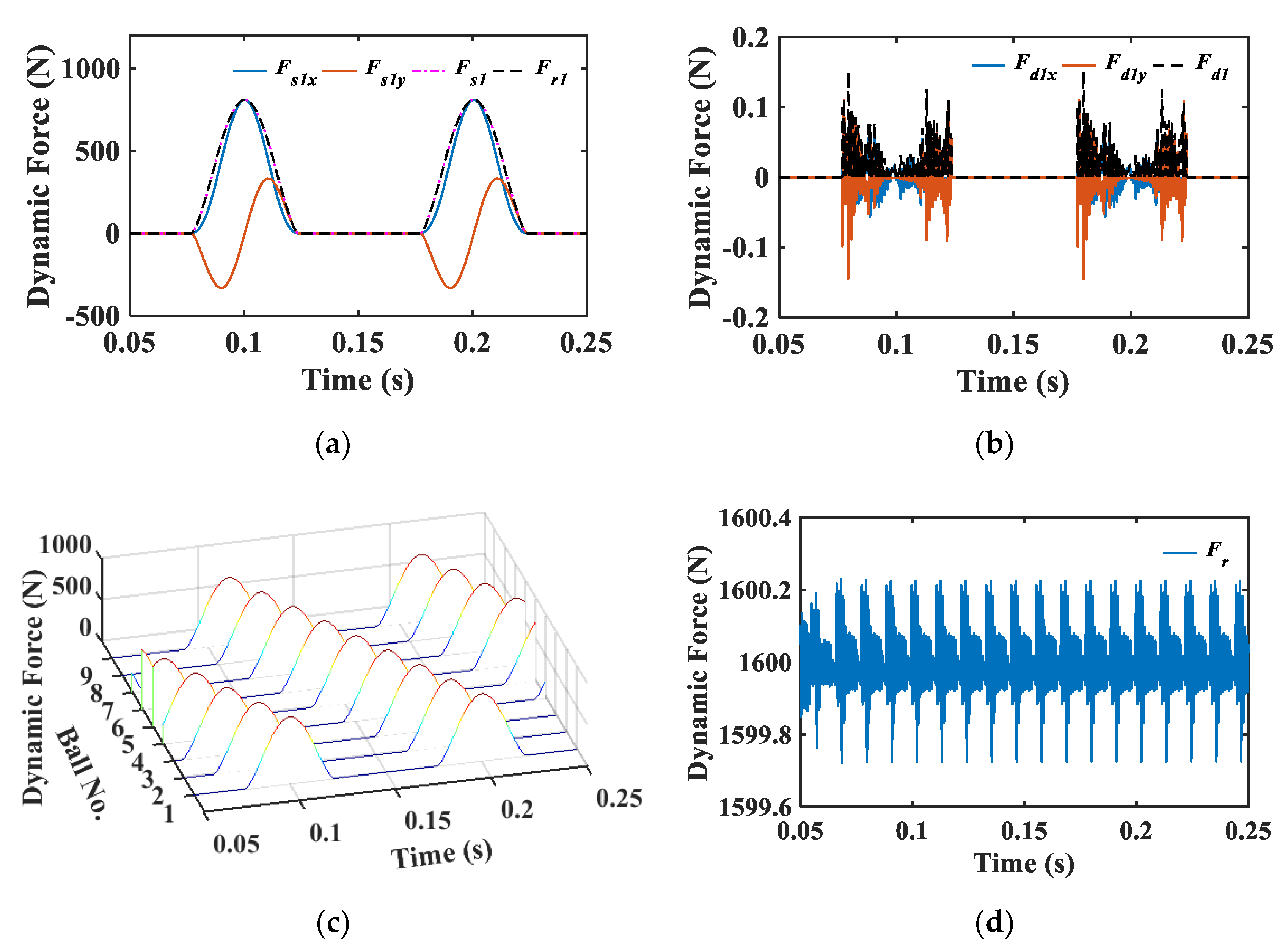
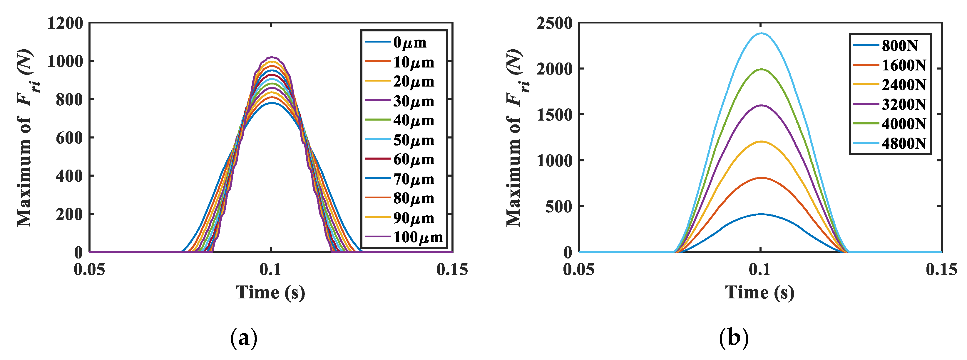
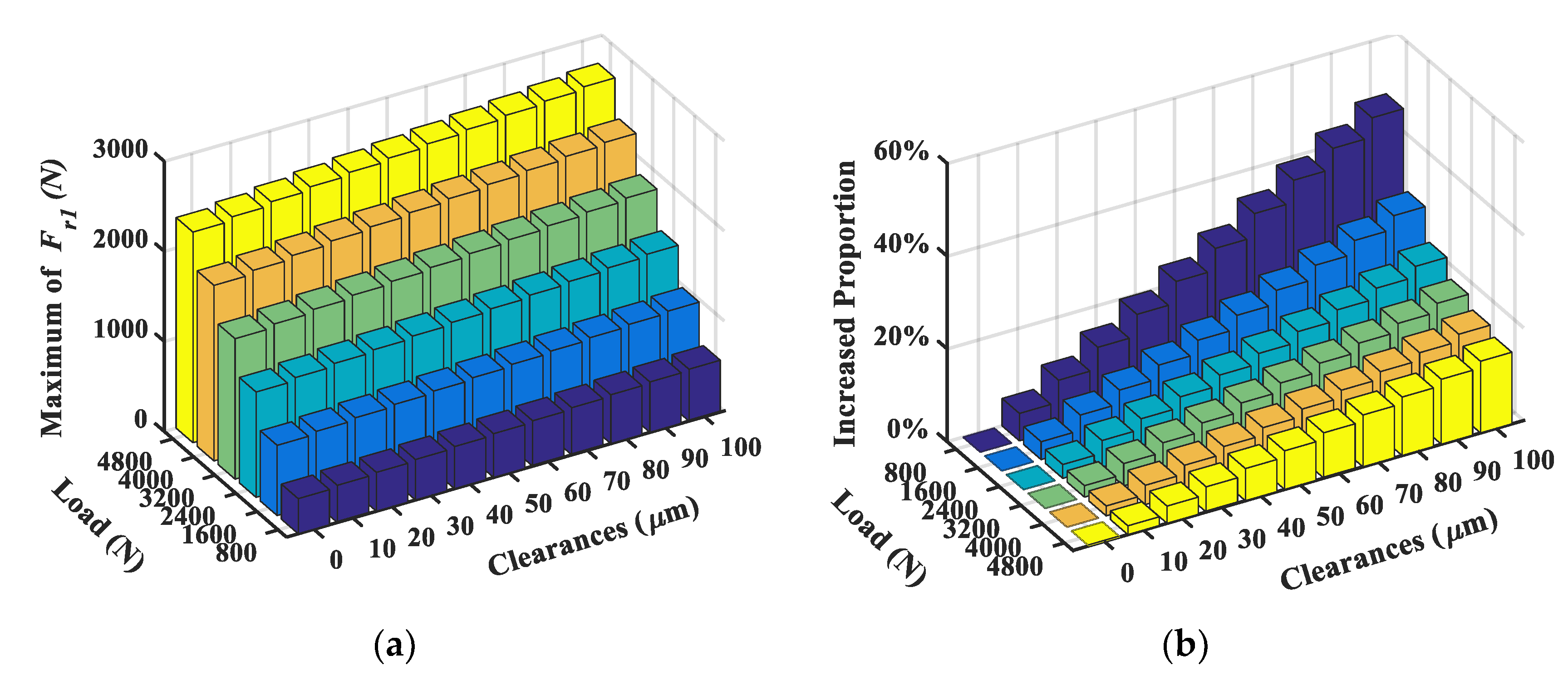
4.1. Dynamic Force Analysis

Considering that the dynamic force exhibited an impulse wave with a certain width in a contact cycle, without loss of generality, maximum force of the first ball was extracted under different clearance and load conditions. Figure 11a,b depict the dynamic forces under the load of 1600 N and the clearance of 10 μ m , respectively. Under the same load, the width of the dynamic force decreased with the clearances, while the magnitude increased with the clearances. Separately, under the same clearance, only the magnitude increased with the loads, while the width remained unchanged.
To explore the influence of dynamic force on bearing life, the maximum of the dynamic force under all conditions is shown in Figure 12a. The results showed an uptrend in both directions. Compared with 0 μ m under each load, the increased proportion of the magnitude also showed an uptrend with the increase in clearances, as shown in Figure 12b. However, the proportion displayed an opposite trend with the increase in loads. This means that under relatively light load, the influence of clearances on dynamic force is more significant. Taking the load of 1600 N as an example, when clearances ranged from 0 to 100 μ m , the maximum dynamic force increased by about 30%. Such an increase can cause a reduction in life factor by about 30% [16], as the amplitude and profile of dynamic force significantly influence the bearing fatigue life [16,32]. In this way, it could provide sufficient lead time for WT maintenance [33].

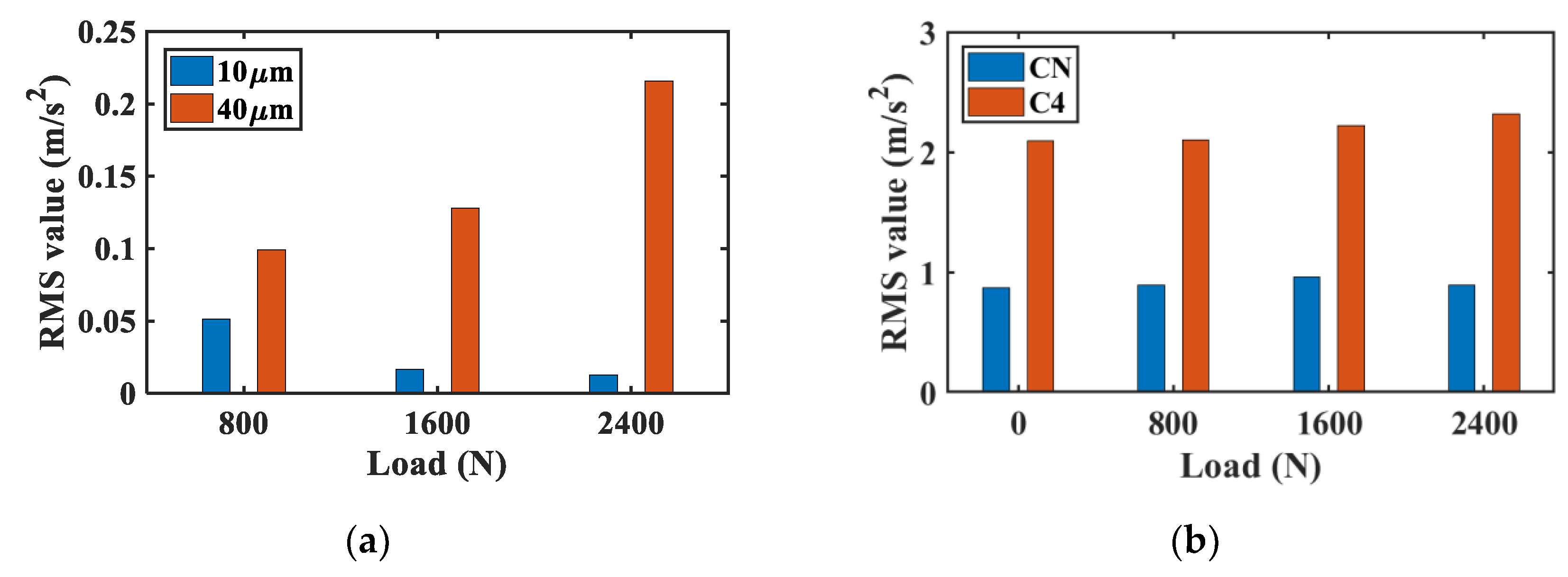
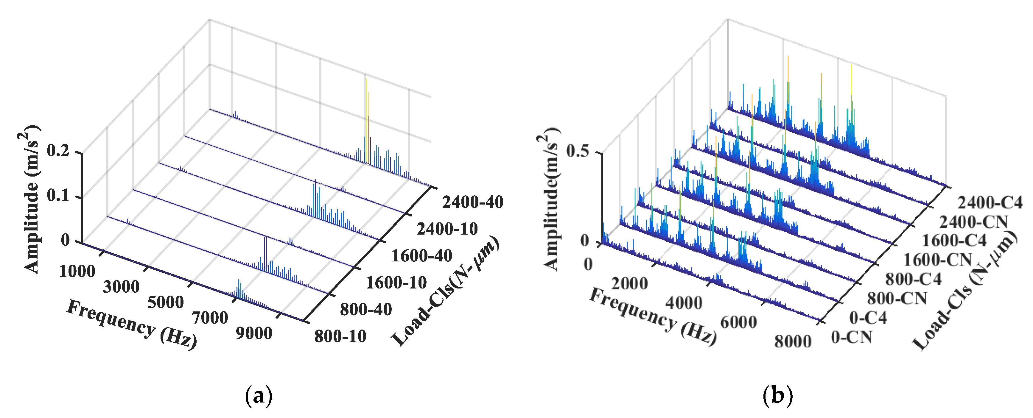
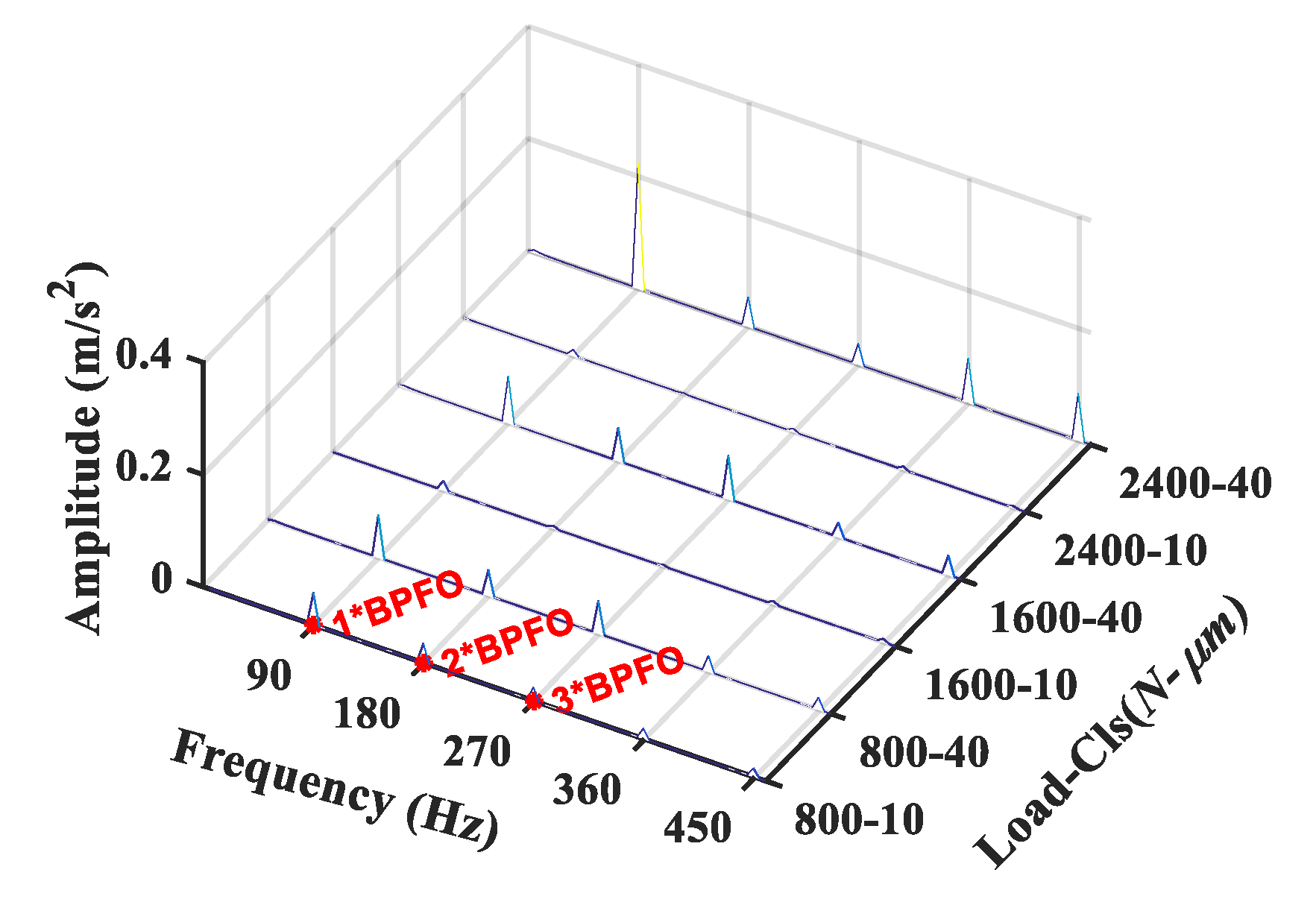
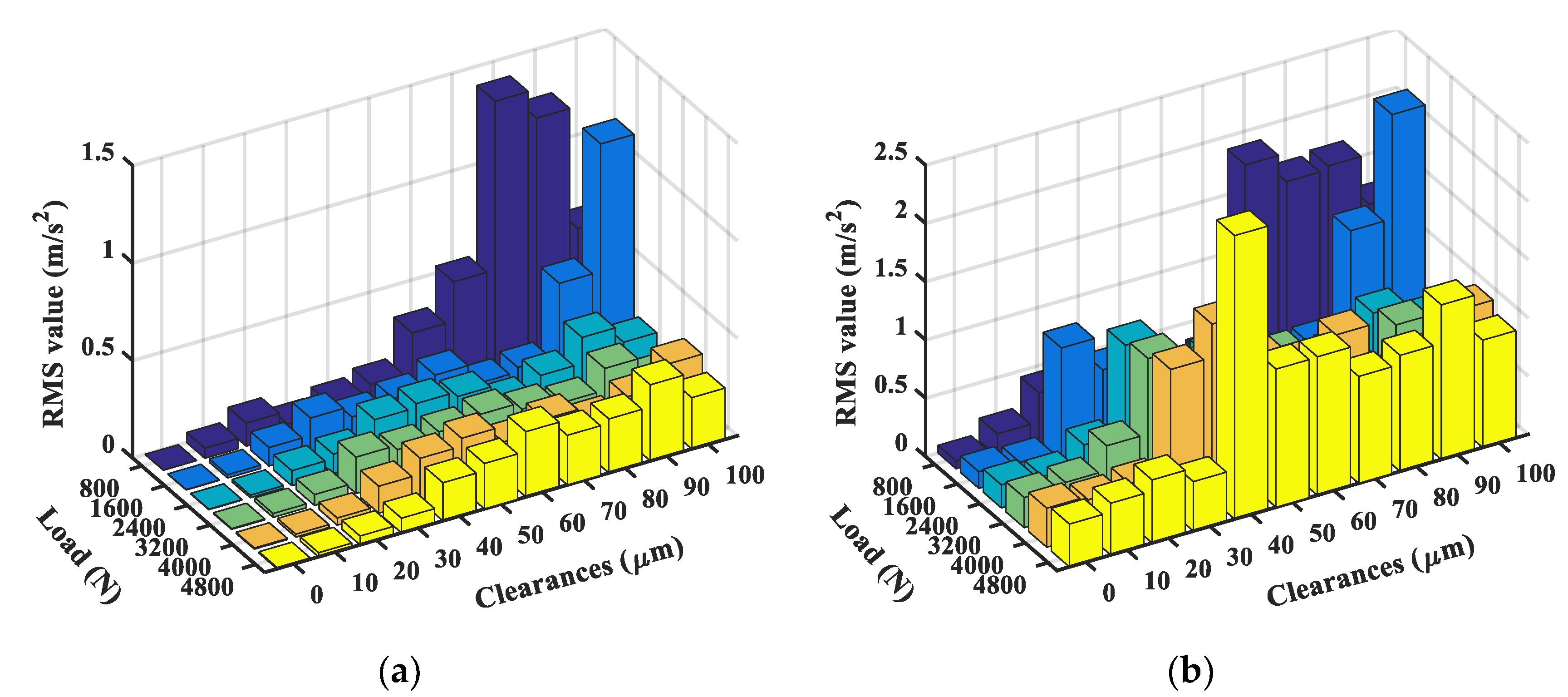
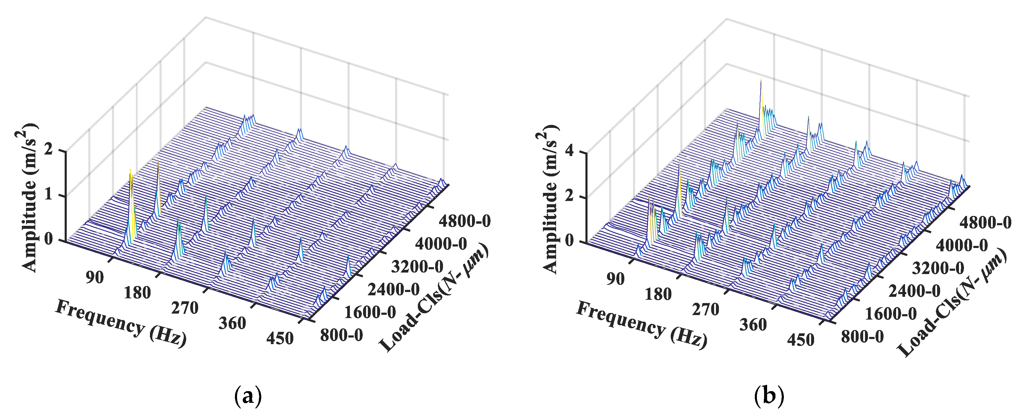
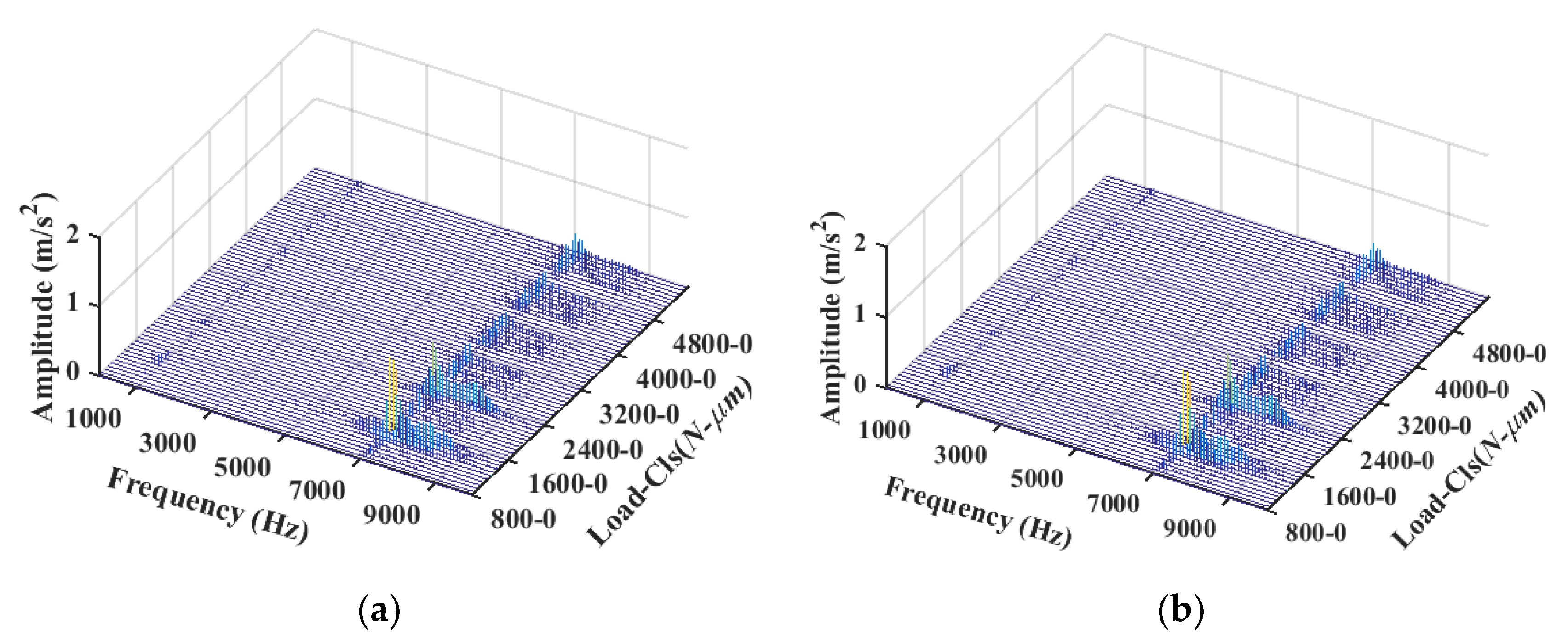
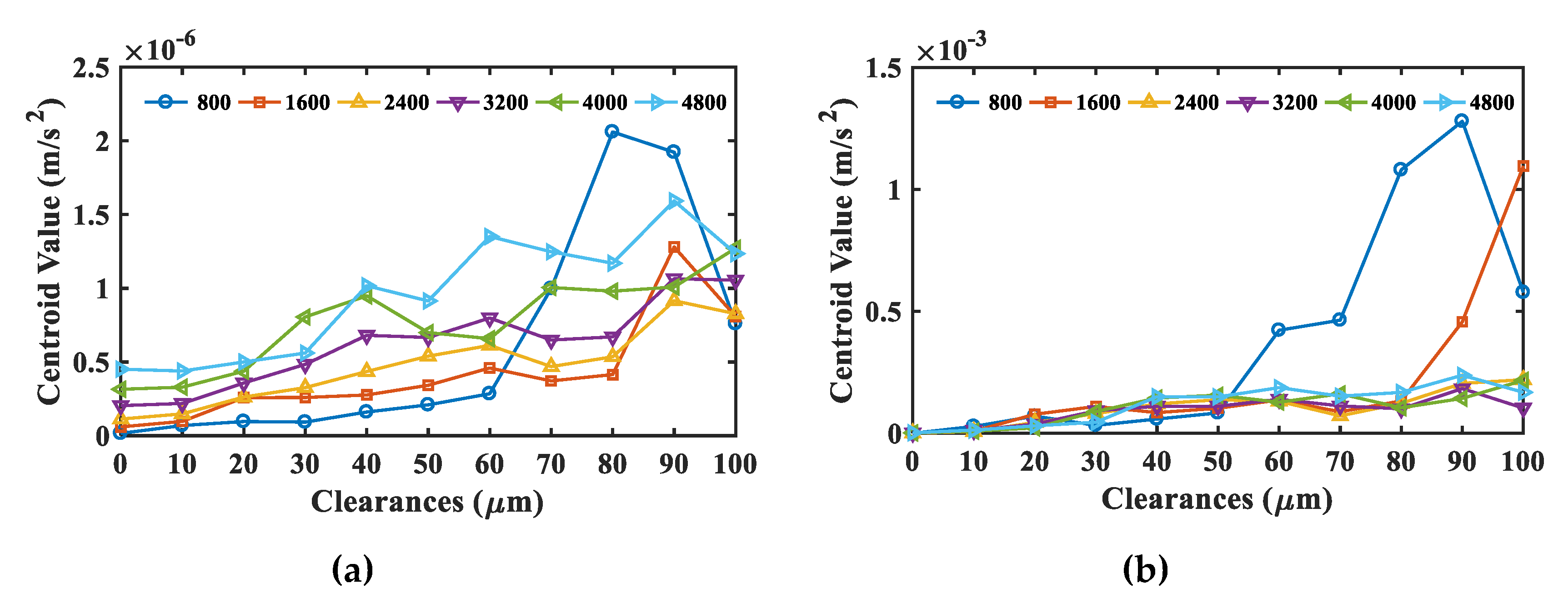
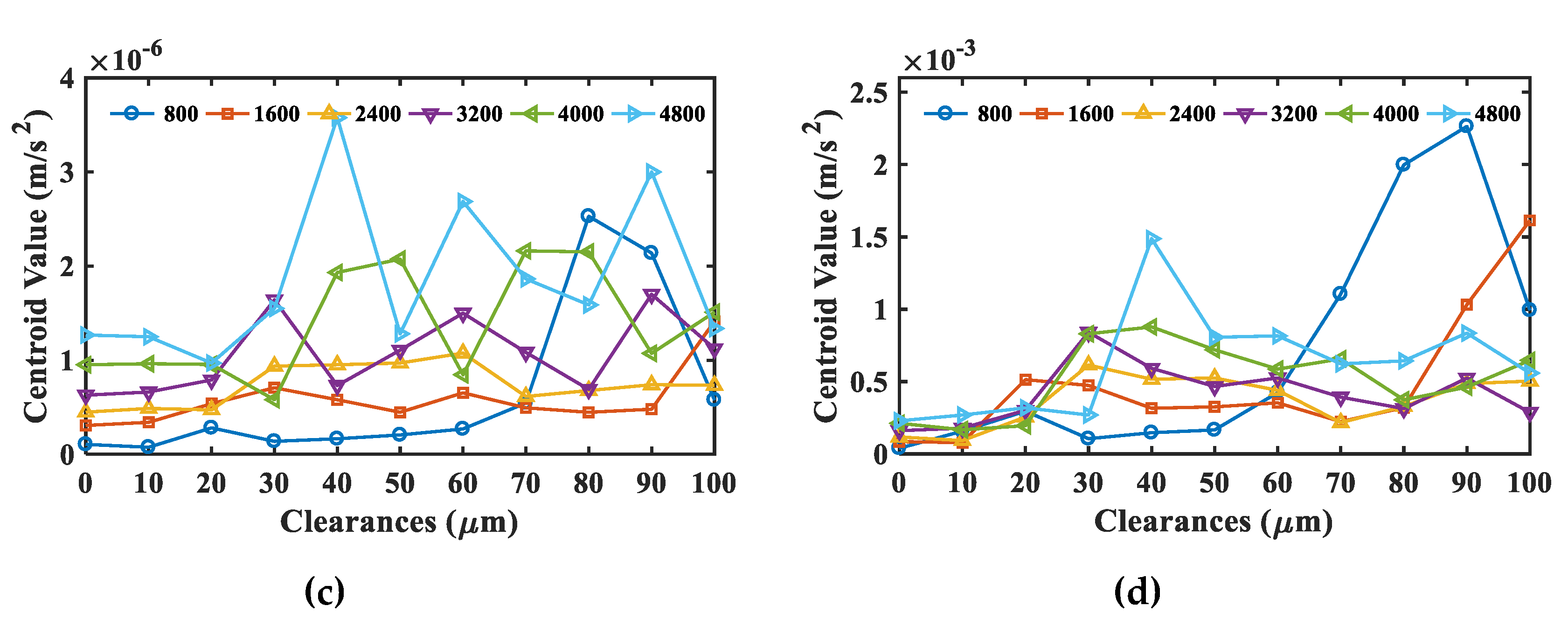
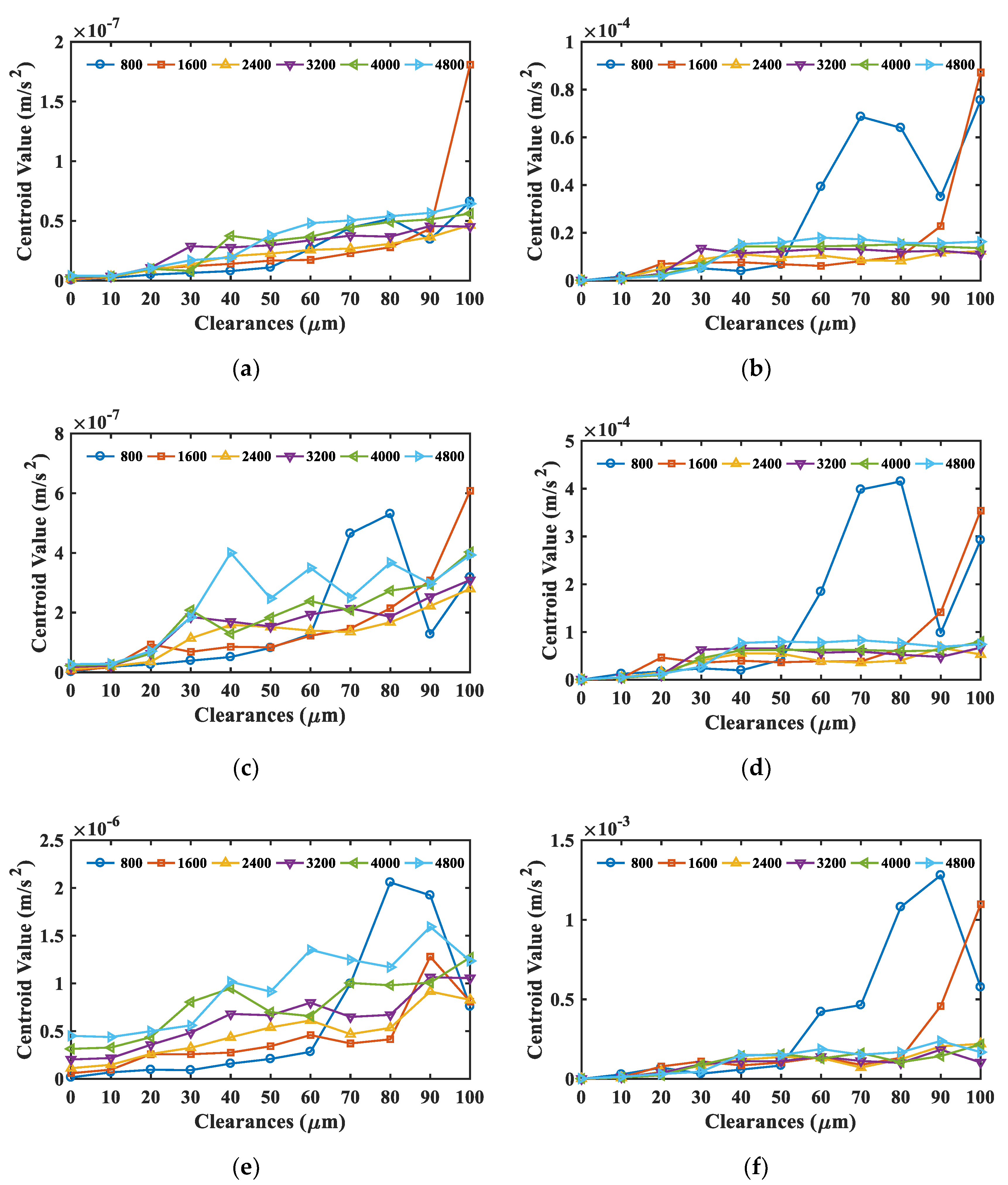
4.2. Bearing Clearance Monitoring

In condition monitoring practice, vibration responses in the time domain are often evaluated based on RMS value in many systems [34]. Study has shown that RMS value could serve as a leading indicator for early detection of faults in WT, giving WT owners time to schedule operations and maintenance [35]. RMS values of signals in the load and non-load directions under different clearance and load conditions are shown in Figure 13.
In general, excepting the resonance peak in the low-loaded conditions, the RMS value showed an uptrend with the increase in clearance, which was more obvious in the load direction. However, it should be noted that the RMS value was not increasing monotonically with the increment of clearances and loads. In Figure 13a, there is a resonance peak in low-loaded conditions, i.e., 800 and 1600 N. This may have been caused by the differences of the load distribution under different clearance and load conditions. Due to fluctuations of the RMS values, it is not accurate enough to be used as an indicator to reflect the bearing clearance, especially when the load is relatively light. Thus, it is necessary to seek other indicators to monitor the variations of clearances.
The spectrum exhibits the amplitude distribution and energy distribution of each frequency component. Envelope spectrum is an effective tool to reveal the amplitude modulation frequency components [36], which is a widely used method to diagnose bearing faults for mechanical machines. Through the envelope spectrum, as shown in Figure 14, BPFO and its harmonics were the primary modulation source in the bearing vibration signals. Note that ‘’800-0” in Figure 14 means the load is 800 N and the clearance is 0μm. Such expression is adopted in the following figures.
Figure 15 depicts the spectrum of signal in the load and non-load directions, respectively. As can be seen, two peaked regions can be clearly distinguished from the spectrum in both directions, with one in the low frequency band from 500 to 1500 Hz and one in the high frequency band from 6000 to 9000 Hz. In addition, it can be observed that the low frequency band shifted right slightly with the increase in loads.
Due to the difference between the low and high frequency band, spectral centroid [37] based on FFT spectrum was calculated according to Equation (16), as shown in Figure 16.
C e n t r o i d = n = 0 N 1 f ( n ) x ( n ) n = 0 N 1 x ( n )
From the spectral centroid, signals of the low frequency band and the high frequency band in the load direction showed a relatively obvious uptrend with the increase in clearance. However, when under a relatively light load, especially 800 and 1600 N, the centroid line displayed large fluctuations under large clearances. In addition, in either the load direction or non-load direction, these lines showed much crossing, which still brought difficulty for monitoring bearing clearance. Fortunately, when under a widely used clearance range, from 0 to 60 μ m , these lines showed better separability, which showed a better performance over the RMS value.
In order to verify the effect of the spectral centroid in a real measured signal, the vibration signals of Section 3 were used to calculate the index values. In addition, RMS values of the low frequency band were calculated as a comparison to the spectral centroid, as shown in Figure 17. It was found that the spectral centroid showed a better performance in clearance monitoring.

4.3. Influence of Rotational Speed

To study the influence of rotational speed, simulations under 500 and 1000 rpm were carried out to make a comparison with 1500 rpm based on the spectral centroid values of the low and high frequency bands in the load direction, as shown in Figure 18.
As can be seen, under different rotational speeds, apart from fluctuations under a relatively light load, the spectral centroid showed an uptrend with the increase in clearance in general. In addition, the spectral centroid of the low frequency band in the load direction had a better performance in describing the clearance variations. However, it should be noted that, the rotational speed had an influence on the location of the resonance peak. Taking a load of 800 N as an example, the resonance peak shifted with the increase in rotational speed.

4.4. Discussion

In a WT system, unsteady wind and gusts will lead to high contact stresses on rolling elements and bearing skidding. Investigations show that wear is the main cause of bearing failures. Wear and tear on bearings could result in faults or even fatal breakdowns, causing catastrophic accidents and economic losses. Thus, this study, focusing on the bearing clearances caused by wear, provides a vital reference to accurately monitor the health condition of bearing. In practical application, for a WT real-time online monitoring system dynamic model, the investigated vibration characteristics and indicators can be utilized to show the present and predict the future state and will be updated or adjusted through the test data. Thus, the faults can be detected at an early stage, providing sufficient lead time to perform maintenance on WTs and hence reducing accidents and economic losses.
From all the above analysis, although the dynamic force on each rolling element shows a linear increase with the increase in the clearance and load, it is very difficult to obtain a linear vibration indicator related to bearing clearance. This may be due to the nonlinear effect between the contact force and vibrations. In addition, because the model is established based on ideal assumptions, which inevitably ignored some factors, such as bearing errors and interferences, the responses under different clearance and load conditions will become even more complicated once these factors are taken into consideration. Thus, diagnostic methods and some more advanced approaches are required for nonlinear feature extraction, such as correlation analysis [38], principal component analysis (PCA) [39], time-frequency manifold learning [40,41] and so on.
In future research, on the one hand, the authors will take more factors, such as friction, skidding and lubrication, into consideration, making the simulation closer to the real operating state of bearings. On the other hand, nonlinear feature extraction methods will be applied to the existing data to realize online bearing clearance monitoring.

5. Conclusions

To monitor the bearing health condition at early stages for taking timely maintenance actions, this study has investigated the vibration characteristics of deep groove ball bearings with consecutive increases in clearances and loads. A dynamic model is introduced to gain the vibration responses of a bearing before local defects appearing on raceways. The proposed model is verified based on the good consistency between the numerical simulation and the bearing test rig data.
The dynamic force exhibits as a repetitive impulse train in accordance with the frequency of BPFO. The maximum magnitude shows a significant monotonic increase with clearances, which will lead to a substantial decrease, about 30%, in bearing life time.
Moreover, vibration responses can be used to indicate the changes of clearances. Particularly, BPFO is the dominant modulation component from the envelope spectrum in both the load and non-load directions. RMS and spectral centroid values show an uptrend with the increase in clearances under different operating conditions, especially the spectral centroid of the low frequency band in the load direction, allowing the change in clearances to be monitored with good accuracy. However, the RMS value and spectral centroid show certain fluctuations with increasing bearing clearances, due to the resonance magnification in low-load conditions, which must take special care in predicting changes in clearances. Nevertheless, reducing the resonance effect and finding optimal indicators will be the future study in this subject.

Author Contributions

Conceptualization, F.G.; data curation, formal analysis, methodology, programming, literature review and original draft preparation, M.X.; software and validation, F.G. and M.X.; investigation, G.F. and A.B.; review and editing, M.X., G.F. and Q.H. All authors have read and agreed to the published version of the manuscript.

Funding

This research was funded by Innovating major training projects of Beijing Institute of Technology, Zhuhai, XKCQ-2019-01.

Acknowledgments

The authors gratefully acknowledge the support of the State Key Laboratory of Mechanical Transmission (SKLMT), University of Chongqing University, P.R. China and the Centre for Efficiency and Performance Engineering (CEPE), University of Huddersfield, United Kingdom.

Conflicts of Interest

The authors declare no conflict of interest.

References

  1. Lu, B.; Li, Y.; Wu, X.; Yang, Z. A review of recent advances in wind turbine condition monitoring and fault diagnosis. In Proceedings of the 2009 IEEE Power Electronics and Machines in Wind Applications, Lincoln, NE, USA, 24–26 June 2009. [Google Scholar]
  2. Chen, Z.; Guerrero, J.M.; Blaabjerg, F. A review of the state of the art of power electronics for wind turbines. IEEE Trans. Power Electr. 2009, 24, 1859–1875. [Google Scholar] [CrossRef]
  3. Zhen, D.; Guo, J.; Xu, Y.; Zhang, H.; Gu, F. A Novel fault detection method for rolling bearings based on non-stationary vibration signature analysis. Sensors 2019, 19, 3994. [Google Scholar] [CrossRef] [Green Version]
  4. Wang, Y.; Xu, G.; Zhang, Q.; Liu, D.; Jiang, K. Rotating speed isolation and its application to rolling element bearing fault diagnosis under large speed variation conditions. J. Sound. Vib. 2015, 348, 381–396. [Google Scholar] [CrossRef]
  5. De Azevedo, H.D.M.; Araújo, A.M.; Bouchonneau, N. A review of wind turbine bearing condition monitoring: State of the art and challenges. Renew. Sustain. Energy Rev. 2016, 56, 368–379. [Google Scholar] [CrossRef]
  6. Randall, R.B.; Antoni, J. Rolling element bearing diagnostics—A tutorial. Mech. Syst. Signal Process. 2011, 25, 485–520. [Google Scholar] [CrossRef]
  7. Tse, P.W.; Peng, Y.A.; Yam, R. Wavelet analysis and envelope detection for rolling element bearing fault diagnosis-their effectiveness and flexibilities. J. Vib. Acoust. 2001, 123, 303–310. [Google Scholar] [CrossRef]
  8. Lei, Y.; Lin, J.; He, Z.; Zi, Y. Application of an improved kurtogram method for fault diagnosis of rolling element bearings. Mech. Syst. Signal Process. 2011, 25, 1738–1749. [Google Scholar] [CrossRef]
  9. Samanta, B.; Al-Balushi, K.R. Artificial neural network based fault diagnostics of rolling element bearings using time-domain features. Mech. Syst. Signal Process. 2003, 17, 317–328. [Google Scholar] [CrossRef]
  10. Desbazeille, M.; Randall, R.B.; Guillet, F.; El Badaoui, M.; Hoisnard, C. Model-based diagnosis of large diesel engines based on angular speed variations of the crankshaft. Mech. Syst. Signal Process. 2010, 24, 1529–1541. [Google Scholar] [CrossRef]
  11. Chen, X.; Wang, S.; Qiao, B.; Chen, Q. Basic research on machinery fault diagnostics: Past, present, and future trends. Front. Mech. Eng. 2018, 13, 264–291. [Google Scholar] [CrossRef] [Green Version]
  12. McFadden, P.D.; Smith, J.D. Model for the vibration produced by a single point defect in a rolling element bearing. J. Sound. Vib. 1984, 96, 69–82. [Google Scholar] [CrossRef]
  13. Liu, J.; Shao, Y.; Zhu, W.D. A new model for the relationship between vibration characteristics caused by the time-varying contact stiffness of a deep groove ball bearing and defect sizes. J. Tribol. 2015, 137, 0311011. [Google Scholar] [CrossRef]
  14. Tazi, N.; Châtelet, E.; Bouzidi, Y. Using a Hybrid Cost-FMEA Analysis for Wind Turbine Reliability Analysis. Energies 2017, 10, 276. [Google Scholar] [CrossRef] [Green Version]
  15. Tazi, N.; Châtelet, E.; Bouzidi, Y. Wear analysis of wind turbine bearings. Int. J. Renew. Energy Res. 2017, 7, 2120–2129. [Google Scholar]
  16. Oswald, F.B.; Zaretsky, E.V.; Poplawski, J.V. Effect of internal clearance on load distribution and life of radially loaded ball and roller bearings. Tribol. Trans. 2012, 55, 245–265. [Google Scholar] [CrossRef]
  17. D’Amato, R.; Calvo, R.; Ruggiero, A.; Gómez, E. Measurement capabilities for ball bearing wear assessment. Procedia Manuf. 2017, 13, 647–654. [Google Scholar] [CrossRef]
  18. Halme, J.; Andersson, P. Rolling contact fatigue and wear fundamentals for rolling bearing diagnostics-state of the art. Proc. Inst. Mech. Eng. Part J J. Eng. Tribol. 2010, 224, 377–393. [Google Scholar] [CrossRef]
  19. Harris, T.A.; Kotzalas, M.N. Advanced Concepts of Bearing Technology: Rolling Bearing Analysis; CRC Press: Boca Raton, FL, USA, 2006. [Google Scholar]
  20. Yakout, M.; Nassef, M.G.A.; Backar, S. Effect of clearances in rolling element bearings on their dynamic performance, quality and operating life. J. Mech. Sci. Technol. 2019, 33, 2037–2042. [Google Scholar] [CrossRef]
  21. Ocak, H.; Loparo, K.A.; Discenzo, F.M. Online tracking of bearing wear using wavelet packet decomposition and probabilistic modeling: A method for bearing prognostics. J. Sound. Vib. 2007, 302, 951–961. [Google Scholar] [CrossRef]
  22. Rehab, I.; Tian, X.; Gu, F.; Ball, A. The influence of rolling bearing clearances on diagnostic signatures based on a numerical simulation and experimental evaluation. Int. J. Hydromechatron. 2018, 1, 16–46. [Google Scholar] [CrossRef]
  23. Zmarzły, P. Influence of the internal clearance of ball bearings on the vibration level. Eng. Mech. 2018, 2018, 961–964. [Google Scholar]
  24. Georgiadis, A.; Gong, X.; Meier, N. Vibration analysis based on the spectrum kurtosis for adjustment and monitoring of ball bearing radial clearance. In MATEC Web of Conferences; EDP Sciences: Les Ulis, France, 2018. [Google Scholar]
  25. Meier, N.; Ambrożkiewicz, B.; Georgiadis, A.; Litak, G. Verification of measuring the bearing clearance using kurtosis, recurrences and neural networks and comparison of these approaches. In Proceedings of the IEEE SENSORS, Montreal, ON, Canada, 27–30 October 2019; pp. 1–4. [Google Scholar]
  26. Wang, J.; Xu, M.; Zhang, C.; Huang, B.; Gu, F. Online Bearing Clearance Monitoring Based on an Accurate Vibration Analysis. Energies 2020, 13, 389. [Google Scholar] [CrossRef] [Green Version]
  27. Sunnersjö, C.S. Varying compliance vibrations of rolling bearings. J. Sound. Vib. 1978, 58, 363–373. [Google Scholar] [CrossRef]
  28. Arslan, H.; Aktürk, N. An investigation of rolling element vibrations caused by local defects. J. Tribol. 2008, 130, 041101. [Google Scholar] [CrossRef]
  29. Sawalhi, N.; Randall, R.B. Simulating gear and bearing interactions in the presence of faults: Part I. The combined gear bearing dynamic model and the simulation of localised bearing faults. Mech. Syst. Signal Process. 2008, 22, 1924–1951. [Google Scholar] [CrossRef]
  30. Xiao, H.; Zhou, X.; Liu, J.; Shao, Y. Vibration transmission and energy dissipation through the gear-shaft-bearing-housing system subjected to impulse force on gear. Measurement 2017, 102, 64–79. [Google Scholar] [CrossRef]
  31. Liu, J.; Shao, Y. Dynamic modeling for rigid rotor bearing systems with a localized defect considering additional deformations at the sharp edges. J. Sound. Vib. 2017, 398, 84–102. [Google Scholar] [CrossRef]
  32. Nagatomo, T.; Takahashi, K.; Okamura, Y.; Kigawa, T.; Noguchi, S. Effects of load distribution on life of radial roller bearings. J. Tribol. 2012, 134, 021101. [Google Scholar] [CrossRef]
  33. Cheng, F.; Qu, L.; Qiao, W. Fault prognosis and remaining useful life prediction of wind turbine gearboxes using current signal analysis. IEEE Trans. Sustain. Energy 2017, 9, 157–167. [Google Scholar] [CrossRef]
  34. Večeř, P.; Kreidl, M.; Šmíd, R. Condition indicators for gearbox condition monitoring systems. Acta Polytechnica 2005, 45. [Google Scholar] [CrossRef]
  35. Igba, J.; Alemzadeh, K.; Durugbo, C.; Eiriksson, E.T. Analysing RMS and peak values of vibration signals for condition monitoring of wind turbine gearboxes. Renew. Energy 2016, 91, 90–106. [Google Scholar] [CrossRef] [Green Version]
  36. Feng, Z.; Liang, M.; Zhang, Y.; Hou, S. Fault diagnosis for wind turbine planetary gearboxes via demodulation analysis based on ensemble empirical mode decomposition and energy separation. Renew. Energy 2012, 47, 112–126. [Google Scholar] [CrossRef]
  37. Schubert, E.; Wolfe, J.; Tarnopolsky, A. Spectral centroid and timbre in complex, multiple instrumental textures. In Proceedings of the International Conference on Music Perception and Cognition, North Western University, Evanston, IL, USA, 3–7 August 2004. [Google Scholar]
  38. Melzer, T.; Reiter, M.; Bischof, H. Nonlinear feature extraction using generalized canonical correlation analysis. In International Conference on Artificial Neural Networks; Springer: Heidelberg/Berlin, Germany, 2001. [Google Scholar]
  39. Widodo, A.; Yang, B.S. Application of nonlinear feature extraction and support vector machines for fault diagnosis of induction motors. Expert Syst. Appl. 2007, 33, 241–250. [Google Scholar] [CrossRef]
  40. He, Q. Time–frequency manifold for nonlinear feature extraction in machinery fault diagnosis. Mech. Syst. Signal Process. 2013, 35, 200–218. [Google Scholar] [CrossRef]
  41. Ding, X.; He, Q. Time–frequency manifold sparse reconstruction: A novel method for bearing fault feature extraction. Mech. Syst. Signal Process. 2016, 80, 392–413. [Google Scholar] [CrossRef]
Figure 1. Diagram of a bearing vibration system.
Applsci 10 04731 g001
Figure 2. Schematic diagram of the dynamic forces: (a) spring, (b) damping and (c) resultant force.
Applsci 10 04731 g002
Figure 3. Results of (a) vibration acceleration, (b) spectrum and (c) envelope spectrum of the sensor.
Applsci 10 04731 g003
Figure 4. Dynamic force of (a) spring and (b) damping, resultant force of (c) each ball and (d) all balls.
Applsci 10 04731 g004
Figure 5. Experimental setup: (a) illustrative diagram and (b) schematic drawing.
Applsci 10 04731 g005
Figure 6. Waveforms under different loads, (a) 0 N, (b) 800 N, (c) 1600 N, (d) 2400 N.
Applsci 10 04731 g006
Figure 7. RMS value of (a) simulation signal in the load direction and (b) test signal.
Applsci 10 04731 g007
Figure 8. Frequency spectrum of (a) simulation signal in load the direction and (b) test signal.
Applsci 10 04731 g008
Figure 9. Envelope spectrum of simulation signal under different clearances and loads.
Applsci 10 04731 g009
Figure 10. Envelope spectrum of CN and C4 bearings under (a) 0 N, (b) 800 N, (c) 1600 N, (d) 2400 N.
Applsci 10 04731 g010aApplsci 10 04731 g010b
Figure 11. Dynamic force impulse (a) under different clearances (load is 1600 N) and (b) under differnet load (clearances is 10 μ m ).
Applsci 10 04731 g011
Figure 12. Maximum of the dynamic force F r 1 (a) under different clearances and loads and (b) increased proportion compared with 0 μ m .
Applsci 10 04731 g012
Figure 13. RMS value in (a) load and (b) non-load direction.
Applsci 10 04731 g013
Figure 14. Envelope spectrum in (a) load and (b) non-load direction.
Applsci 10 04731 g014
Figure 15. FFT spectrum in (a) load and (b) non-load direction.
Applsci 10 04731 g015
Figure 16. Spectral centroid: (a) low and (b) high frequency band in the load direction, (c) low and (d) high frequency band in non-load direction.
Applsci 10 04731 g016aApplsci 10 04731 g016b
Figure 17. (a) RMS and (b) spectral centroid values of bearing test rig data.
Applsci 10 04731 g017
Figure 18. Spectral centroid of low frequency band and high frequency band in the load direction under the rotational speed of (a,b) 500 rpm, (c,d) 1000 rpm and (e,f) 1500 rpm.
Applsci 10 04731 g018
Table 1. Main geometry parameters of deep groove ball bearing 6206.
NotationDescriptionValue
d Nominal bore diameter ( mm )30
D Nominal outside diameter ( mm )62
d i Inner race diameter ( mm )37.48
d o Outer race diameter ( mm )56.45
d m Pitch diameter ( mm )46.96
d b Ball diameter ( mm )9.485
d b Original radial clearance ( μ m )0
N b Number of rollers9
α Contact angle (˚)0
Table 2. Physical properties for simulation study.
NotationDescriptionValue
m s Mass of shaft (kg)1.32
m h Mass of house (kg)0.46
m r Mass of sensor (kg)0.02
m b Mass of each ball (kg) 2.95 × 10 3
K h Stiffness of house (N/m) 1.2 × 10 9
K r Stiffness of sensor (N/m) 4 × 10 7
C h Damping of house939.62
C r Damping of sensor17.89
Table 3. Experiment test bearing clearance values.
Bearing TypeBearing ClassClearance (µm)
6206 ZZCN8.33
C440.86
Table 4. Clearance values of deep groove ball bearings.
Bore Diameter
d (mm)
over Include
C2
(μm)
Min Max
CN
(μm)
Min Max
C3
(μm)
Min Max
C4
(μm)
Min Max
C5
(μm)
Min Max
--- 2.50 64 1110 20--- ------ ---
2.5 60 72 138 23--- ------ ---
6 100 72 138 2314 2920 37
10 180 93 1811 2518 3325 45
18 240 105 2013 2820 3628 48
24 301 115 2013 2823 4130 53

