Abstract
A mirror-based Schwarzschild microscope with a wide spectrum and a long working distance was investigated to perform precise assemblage of detectors. We employed a gradient square method to construct the evaluation function for realizing accurate quantitative analysis of image defocusing. By imaging a resolution target that corresponded to 228 line pairs per mm, the validity and imaging ability of the system was proven. The results of repeated focusing tests yielded a standard deviation of 0.75 μm, which indicated high performance accuracy for the focusing system. The proposed system has potential applications in industrial inspection and focusing detection.
1. Introduction
The significant features of the new generation of remote spatial sensing technology are wide field of view and high resolution. To realize these features, remote sensing cameras in remote sensing satellites with large apertures and high resolutions require the use of a large, high resolution Charge Coupled Device(CCD) array device [1,2,3]. Due to technological limitations, a monolithic CCD cannot meet the large-size and large field-of-view requirements for the image sensor. In order to obtain a larger image sensor without high additional costs, the method commonly used is multi-CCD stitching assemblage, in which several CCDs with different wavelength filters are assembled in a particular arrangement to form a large CCD array [4,5]. However, a significant challenge for this approach is that precise auxiliary assembly equipment is needed for precise stitching assemblage of the CCD array.
The equipment needs to realize the observation of stitching state and effect evaluation by high magnification microscopic imaging of CCD pixel. In addition, the system should have the function of judging the defocusing state of the stitching focal plane, which can realize the precise focusing of the splicing surface. The use of an ordinary microscope is limited by the existence of a spectro-prism and mounting mechanism, which requires the microscope instrument to have an ultra-long working distance to ensure that CCD can be observed through the spectro-prism and mounting mechanism. In order to achieve precise stitching assemblage of a wide-spectrum CCD, the specialized instrument used for precise aiming and positioning must be apochromatic to ensure that each splicing CCD is on the same plane. The accuracy of CCD stitching assemblage is generally of the order of microns. Therefore, as well as having a compact structure, the instruments used for precise stitching assemblage must meet the requirements of long working distance, apochromatism, and high magnification to ensure accuracy and convenience. Considering the characteristics of ultra-long working distance, wide spectrum and high imaging quality, the micro-imaging instrument is not only needed for stitching assemblage equipment, but also for other fields such as microscopic observation in extreme environment, microcircuit welding, etc.
Mirror-based reflective imaging systems have some unique advantages over refraction imaging systems. Reflective imaging systems have no chromatic aberration—neither axial nor transverse; in theory, reflective microscopic imaging can be applied to any spectral range [6]. Moreover, reflective systems have a lower cost and produce lower material transmission. Reflective imaging technology is widely used in specialized microscopic imaging fields such as X-ray imaging [7,8,9], extreme-ultraviolet/ultraviolet (EUV/UV) lithography [10], UV-band micro/nanofabrication [11] and near-infrared imaging [12,13].
In this article, we report the use of a mirror-based micro-imaging device to realize micro-sized observation of samples with working distances of several hundreds of millimeters. Based on this device, the automatic focusing system can realize observation and evaluation of the stitching state, and also accurately quantify the defocusing of the image via an automatic focusing image processing method. The automatic focusing system is designed for use in the precise stitching assemblage of a multi-window CCD camera.
2. Materials and Methods
2.1. System Design
A high performance microscope instrument forms the core of the CCD splicing equipment device which is used to meet the strict requirements mentioned. A schematic diagram of the focusing system for the microscopic imaging assembly setup is shown in Figure 1, and the main parameters of the microscopic imaging system are shown in Table 1.
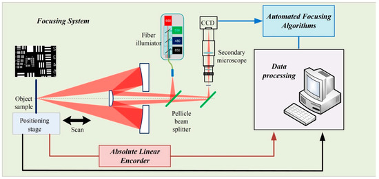
Figure 1.
Schematic diagram of the focusing system of the mirror-based microscopic imaging assembly setup.

Table 1.
Parameters of microscopic imaging system.
In this work, a two-stage amplification method was used to meet the requirements for magnification and structure-size of the system. The overall magnification of the system is the product of the magnification of the front-end reflective objective and the magnification of the second-stage micro-module. Because the objective lens is a reflective optic, the first stage of magnification does not produce chromatic aberration in the image and can simultaneously satisfy the requirements for ultra-long working distance, broad spectral acceptance, and large numerical aperture. The image generated by the first amplification stage is magnified by the secondary microscope module to meet the requirements of compact structure and high magnification. In order to ensure imaging quality when using the secondary module, the image plane of the first-stage of magnification coincides with the object plane of the secondary imaging module; after both stages of amplification, the image of the object is formed on a wide-spectrum CCD.
The details of the design theory for a low-obscuration mirror-based objective were obtained in a previous study [14]. Based on the overall size of the microscopic system, we selected the magnification of the objective lens to be 6.5× and 0.13 was the numerical aperture (NA) of the objective lens; the obscuration ratio of the system was set to 4%. Zemax simulation results revealed that the effect of obscuration on imaging quality can be neglected. The working distance of the mirror-based objective is 525 mm, which is much greater than the working distance of typical microscope objectives with the same NA.
A Zeiss EC Plan Neofluar objective was selected as the secondary microscope objective; its NA is 0.075. The working distance of the Zeiss EC Plan Neofluar 2.5× objective is 9.5 mm and its magnification is 2.5×. The secondary microscope module was further combined with a Sony near-infrared camera (EI-30CE) and tube mirror (VMU-V, Mitutoyo), which magnifies the image twice, and then, the magnified image is imaged on the CCD. The microscope has good imaging performance at wavelengths in the ultraviolet to near infrared range, especially for the 400–1100 nm band, and its transmittance is as much as 80%.
The lighting source consists of four high power LED channels, each of which corresponds to a single wavelength, 480, 550, 660 or 850 nm. The light is introduced into the optical system through an optical fiber. The illuminating lens group and the mirror-based objective constitute the light path for Kohler illumination.
Figure 2 compares the modulation transfer function (MTF) of the designed mirror-based objective with that of the ideal optical system without obscuration. As shown in Figure 2a, the MTF of the mirror-based objective we designed is close to that of the ideal image when the half-field is smaller than 0.3 mm; due to obscuration effect, the performance of the objective in the middle and low frequency is slightly lower than that of the unobscured objective. Figure 2b shows the MTF of the optical system for larger fields. It can be seen that the MTF corresponding to a 1 mm half-field still basically coincides with the ideal MTF. When the field of view increases further, the MTF of the mentioned mirror-based objective is lower than that for an unobscured objective in the low and medium spatial frequencies. It should be noted in particular that the optical system has been carefully optimized, therefore, the different curves (T, S. T DIFF. Lim, etc.,) in the MTF curve (Figure 2a) in the small field of view are close to coincidence. Therefore, it cannot be completely independently reflected in the figure.
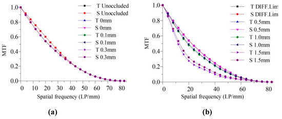
Figure 2.
Comparison of modulation transfer function (MTF) curves for the mirror-based objective with the ideal MTF. (a) MTF curve for smaller fields; (b) MTF curves for larger fields.
In this study, the Monte Carlo method tolerance analysis was performed using ZEMAX; the tolerance settings are shown in Table 2 and the the simulation times were 10,000. The results of the tolerance analysis are shown in Table 3. The RMS spot size for the spatial image was used as the evaluation criterion.
Table 2.
Tolerances of the mirror-based objective.
Table 3.
Monte Carlo tolerance analysis results at the relay image.
The primary and secondary mirrors of the aspheric Schwarzschild objective are made of fused quartz by a traditional optical processing method. The diameters of the two mirrors are 210 and 29 mm. Protected aluminum film is used to cover the machined surfaces. The results of the optical surface (without coating) are measured by a Fizeau interferometer, which indicates the deviation between the actual surface and the ideal surface, as shown in Figure 3. It can be seen that the peak-to-valley (PV) value of the surface was 0.135 and 0.08 λ (λ = 632.8 nm), respectively, for the two mirrors. According to Rayleigh’s judgment, as the surface PV value is less than λ/4, the surface error will have very little effect on the image quality.
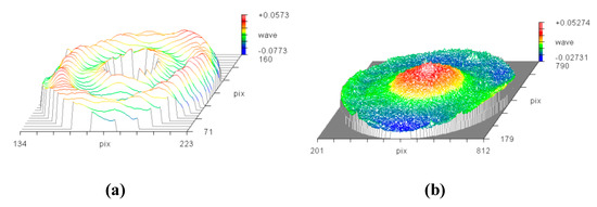
Figure 3.
Surface measurement results for (a) primary mirror and (b) secondary mirror.
A diagram and photograph of the microscopic measurement integrated device are shown in Figure 4. In order to ensure the positioning accuracy and straightness of the motion mechanism of the focusing system, an air-bearing guide rail and roller screw are used as the driving mechanism, a brushless DC servo motor is used as the driving motor, and a grating encoder is used as the feedback sensor. Motion positioning accuracy better than 0.5 μm can be achieved with this motion control system. All of the devices were placed on an active self-leveling isolation system in order to eliminate, as much as possible, the effects of vibrations on measurement results.
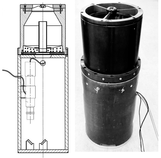
Figure 4.
Microscopic measurement integrated device.
2.2. Auto-Focusing Algorithm
In focusing methods based on automatic image processing, a series of images with different focusing states can be obtained by combining the high performance imaging system mentioned above with displacement driving control; each image sequence is evaluated and normalized, and then, the evaluation function curve is calculated by interpolation. The focusing algorithm for digital image processing is divided into two principal parts—selecting the focusing evaluation function and fitting the curve to determine the focusing position [15].
In the focusing process, the defocus state is judged by the change in sharpness produced by the defocusing of the image. The current frame image and the next frame image are evaluated, and the defocusing direction and defocusing amount of the target are judged based on a comparison of the analysis results for the different frames. Then, the relative position between the measured part and the optical system is changed until the optimal focal position is achieved.
During the process of focusing, the main consideration is whether the boundary and details of the image are clear in the spatial domain, i.e., whether the high frequency components of the image are rich in the frequency domain. Meanwhile, due to the low gray value and gray gradient of the image, defocusing means that there is less information to represent the image sharpness in the image. Complex environmental factors, such as air-flow jitter, low light, detector noise, etc., will make the optical system used for image collection more vulnerable to the effects of noise. Therefore, when using automatic focus detection technology based on image processing, the image sharpness evaluation function must have a reasonable anti-noise interference capacity while maintaining focus detection with high precision. In order to suppress the effect of noise on the focusing result, we choose a median filter to realize image preprocessing before focusing. Median filtering will be very useful for eliminating the interference of outliers and line segments, especially for impulse noise. It can also protect the boundary contour information while eliminating noise.
In this work, the position of the focal plane is determined by four focusing evaluation functions—the wavelet algorithm, Laplace algorithm, gradient square algorithm and an improved gradient square algorithm. The output of an ideal focusing algorithm is defined as having a maximum value at the best focused image position and decreasing as defocus increases. It is well known that the image quality of the edge area of microscopic imaging is usually worse than that of the central area. In our focusing calculation, instead of using the whole image for calculation, we select the central area of 70% of the whole image as the calculation area. This is because the image quality of the imaging system is reduced due to the larger aberrations in the edge area; meanwhile, the vignetting effect caused by pupil transition in the two-stage magnification system may also be an important reason for this result, where the size of the central area of image is M × N, the gray value of the center pixel is I(x,y), and where 1 ≤ x ≤ M and 1 ≤ y ≤ N.
The Laplacian algorithm applies convolution masks to an image to calculate the pixel I(x,y) and the 4-neighborhood of the pixel [16], which is expressed as follows:
The wavelet algorithm applies both high-pass (H) and low-pass (L) filtering to the image [17]. The synthetic image is divided into four sub-images and the absolute values of HL, LH and HH regions are summed, which is expressed as follows:
The gradient square algorithm calculates the pixel I(x,y) and the 2-neighborhood of the pixel [18], which is expressed as follows:
The improved gradient square algorithm calculates the sum of squares of the differences between the image pixels which eight-neighbor pixels are used as the evaluation function for focusing. The improved gradient square function fully utilizes the pixel information in the neighborhood of each pixel. This method presents the better gradient characteristics. Meanwhile, more of the edge information of the image is retained in the presence of noise. The mathematical expression of the improved evaluation function is:
It should be noted that, a threshold should be considered in the gradient square algorithm, where [I(x,y) − I(x + i, y + j)]2 > threshold, and the effect of image noise on the autofocusing results is reduced.
By scanning the position of the object measured, a group of images corresponding to different positions is collected. A set of discrete points can be obtained by processing the image according to the focusing evaluation function, and then, the focusing function curve can be obtained by fitting and interpolation. From the curve, we can judge the location of the object when the image is sharper, and confirm the optimal focusing position.
Based on the image focusing evaluation function, the effects of linear shifts and jitter in the image on the evaluation function cannot be ignored. The “Runge” phenomenon caused by high order polynomial fitting can be eliminated by curve fitting with a smoothing spline. This method can reduce the influence of image shift on the focusing precision and guide an automatic focusing process for the system. The focusing position obtained by this method could meet focusing precision requirements.
3. Results
In this study, imaging characteristics of the focusing system were evaluated by using the method of imaging a 1951USAF resolution target, as shown in Figure 5. Initially, it is placed near the focal plane of the objective lens. The focusing of the resolution target with the microscope measuring device was realized by the automated focusing method described above.
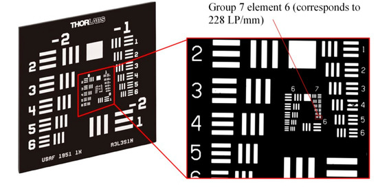
Figure 5.
The 1951USAF resolution target using for evaluated the microscopic imaging system.
At the optimum focusing position, four wavelength LED light sources (λ = 480, 550, 660, and 850 nm) were successively connected by an optical fiber to observe the effects of imaging the resolution target under illumination by different wavelengths, as shown in Figure 6. The minimum line pair position shown in Figure 6 is the group 7 element 6 pattern of 1951USAF resolution target, which corresponds to 228 line pairs per mm (LP/mm). It can be seen that under illumination by all four wavelengths, the microscope can clearly image the resolution target. The horizontal and vertical intensity profiles of the four images in group 7 element 5 and group 7 element 6 have been presented.
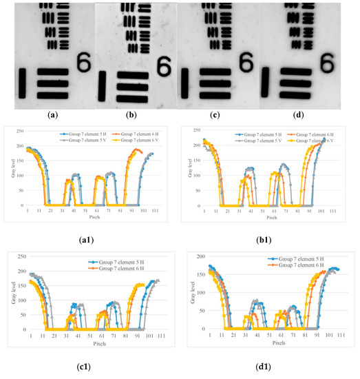
Figure 6.
Imaging results obtained using the 1951USAF resolution target with different wavelength light sources. (a) Image at λ = 480 nm; (b) image at λ = 550 nm; (c) image at λ = 660 nm; (d) image at λ = 850 nm. (a1)–(d1) are the horizontal and vertical intensity profiles of the four images in group 7 element 5 and group 7 element 6, respectively.
During the focusing process, a series of images at λ = 480 nm in different states of defocusing can be obtained by combining the imaging system with displacement driving controls, as illustrated in Figure 7.
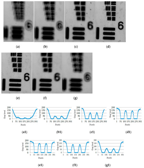
Figure 7.
(a)–(g) Images of resolution target obtained by focusing system with different defocusing states, (a1)–(g1) Intensity profile at group 6 element 1 of each image with different defocusing states.
In order to make valid comparisons, the focusing performance under different evaluation functions is analyzed, applying different evaluation functions—the Laplacian algorithm [16], the wavelet algorithm [17], the gradient square [18] algorithm and the improved gradient square algorithm, which are shown in the Equations (1)–(4). The autofocusing algorithm is used in sequence of Figure 7, each focusing algorithm produces a focusing curve as shown in Figure 8, and the extreme point of the curve is the optimal focusing position. Compared with the four focusing algorithms under the experimental conditions in this paper, the improved gradient algorithm has better performance in focusing, and this algorithm is used for fitting in subsequent experiments.
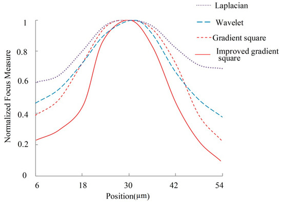
Figure 8.
Comparison of focusing curves for different algorithms used in the proposed system.
In order to verify the accuracy and reliability of our focusing results, repeated focusing experiments were carried out. The resolution target and the microscope measuring device were adjusted to their initial positions, and the focusing process was repeated 25 times. The relative distance between the initial position and the optimal focusing position was obtained, and a comparison of these results for the 25 repeated focusing processes is shown in Figure 9; the peak value and standard deviation of the repeated measurement datasets are 2.74 and 0.75 μm, respectively, which demonstrates that the experimental equipment constructed in this study can achieve high precision focusing.
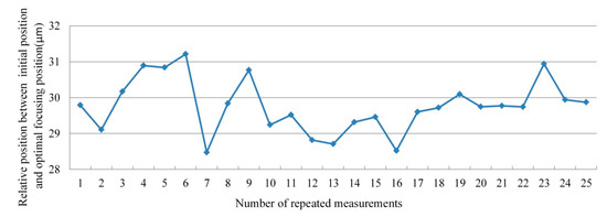
Figure 9.
Distance between initial and optimal focusing positions.
4. Conclusions
In summary, a mirror-based microscope measuring device with a working distance of 525 mm and a numerical aperture of 0.13 was designed and constructed to realize multi-spectral high precision imaging at long working distances and with a large numerical aperture. The influence of noise on image is reduced by image pre-processing. In this paper, four different focusing algorithms are compared and the optimal focusing position is obtained by interpolation fitting. According to the comparison results and the characteristics of the image in this study, the improved gradient square function was selected to construct the evaluation function to realize accurate quantitative analysis of image defocusing. Our device is designed for application in precise stitching assemblage of multi-spectrum detectors, to control defocusing and to align pixels. A standard resolution target can be clearly imaged by the experimental device. The standard deviation of the results of repeated focusing tests that started from the same initial position is 0.75 µm. The system presented in this paper demonstrates the potential applications of mirror-based microscopes in industrial inspection, for example, in the welding of microelectronic devices and other precision mechanical and optical assembly setups.
Author Contributions
Conceptualization, C.W.; Data curation, C.W.; Investigation, W.W.; Methodology, C.W.; Visualization, W.W.; Writing—original draft, T.Z.; Writing—review and editing, T.Z. All authors have read and agreed to the published version of the manuscript
Funding
This research was funded by National Natural Science Foundation of China (Grant No. 51805118); China Postdoctoral Science Foundation (Grant No. 2018M641821); Heilongjiang Postdoctoral Financial Assistance (Grant No. LBH-Z18080).
Conflicts of Interest
The authors declare no conflict of interest.
References
- Yao, Y.; Abidi, B.; Doggaz, N.; Abidi, M. Evaluation of sharpness measures and search algorithms for the auto focusing of high-magnification images. Vis. Inf. Process. XV 2006, 6246, 62460G. [Google Scholar] [CrossRef]
- Zhiming, L.; Ming, Z.; Li, C.; Qingjun, L.; Xuefei, Z.; Xiaohui, Z. Long Range Analysis and Compensation of Smear in Sweep Aerial Remote Sensing. Acta Opt. Sin. 2013, 33, 711001. [Google Scholar] [CrossRef]
- Lee, W.O.; Lee, H.C.; Cho, C.W.; Gwon, S.Y.; Park, K.R.; Lee, H.; Cha, J. Auto-focusing method for remote gaze tracking camera. Opt. Eng. 2012, 51, 063204. [Google Scholar] [CrossRef]
- Meng, X.; Feng, H.; Xu, Z.; Li, Q.; Chen, Y. A method of autofocus for remote sensing camera. In Proceedings of the SPIE-The International Society for Optical Engineering, San Diego, CA, USA, 26 August 2010; Volume 7813. [Google Scholar] [CrossRef]
- Ruck, R. Design Versatility of the Prism Panoramic Camera: The KS-116 And KA-95 Cameras. In Proceedings of the 25th Annual Technical Symposium, San Diego, CA, USA, 12 December 1981; Volume 309, pp. 69–75. [Google Scholar] [CrossRef]
- Vippola, M.; Valkonen, M.; Sarlin, E.; Honkanen, M.; Huttunen, H. Insight to Nanoparticle Size Analysis-Novel and Convenient Image Analysis Method Versus Conventional Techniques. Nanoscale Res. Lett. 2016, 11, 169. [Google Scholar] [CrossRef] [PubMed]
- Artyukov, I.A.; Feschenko, R.; Vinogradov, A.V.; Bugayev, Y.; Devizenko, O.; Kondratenko, V.V.; Kasyanov, Y.; Hatano, T.; Yamamoto, M.; Saveliev, S. Soft X-ray imaging of thick carbon-based materials using the normal incidence multilayer optics. Micron 2010, 41, 722–728. [Google Scholar] [CrossRef] [PubMed][Green Version]
- Barbee, J.T.W. Multilayers for x-ray optics. Tech. Symp. 1985, 563, 2–29. [Google Scholar] [CrossRef]
- Artyukov, I.A.; Bugayev, Y.; Devizenko, O.; Gullikson, E.; Kondratenko, V.V.; Vinogradov, A. X-ray Schwarzschild objective for the carbon window (λ~45 nm). Opt. Lett. 2009, 34, 2930. [Google Scholar] [CrossRef] [PubMed]
- Barysheva, M.M.; E Pestov, A.; Salashchenko, N.; Toropov, M.N.; I Chkhalo, N. Precision imaging multilayer optics for soft X-rays and extreme ultraviolet bands. Phys.-Uspekhi 2012, 55, 681–699. [Google Scholar] [CrossRef]
- Wang, X.; Mu, B.; Jiang, L.; Zhu, J.; Yi, S.; Wang, Z.; He, P. Fabrication of nanoscale patterns in lithium fluoride crystal using a 13.5 nm Schwarzschild objective and a laser produced plasma source. Rev. Sci. Instrum. 2011, 82, 123702. [Google Scholar] [CrossRef] [PubMed]
- Kaucikas, M.; Barber, J.; Van Thor, J.J. Polarization sensitive ultrafast mid-IR pump probe micro-spectrometer with diffraction limited spatial resolution. Opt. Express 2013, 21, 8357–8370. [Google Scholar] [CrossRef] [PubMed]
- Mattson, E.C.; Unger, M.; Clède, S.; Lambert, F.; Policar, C.; Imtiaz, A.; D’Souza, R.; Hirschmugl, C.J. Toward optimal spatial and spectral quality in widefield infrared spectromicroscopy of IR labelled single cells. Analyst 2013, 138, 5610. [Google Scholar] [CrossRef] [PubMed]
- Tan, J.; Wang, C.; Wang, Y.; Wang, W.; Liu, J.; Leach, R.; Hao, L. Long working distance microscope with a low obscuration aspherical Schwarzschild objective. Opt. Lett. 2014, 39, 6699–6702. [Google Scholar] [CrossRef] [PubMed]
- Sha, X.; Li, W.; Lv, X.; Lv, J.; Li, Z. Research on auto-focusing technology for micro vision system. Optik 2017, 142, 226–233. [Google Scholar] [CrossRef]
- Sun, Y.; Duthaler, S.; Nelson, B.J. Autofocusing algorithm selection in computer microscopy. In Proceedings of the 2005 IEEE/RSJ International Conference on Intelligent Robots and Systems, Edmonton, AB, Canada, 2–6 August 2005; pp. 70–76. [Google Scholar]
- Yang, G.; Nelson, B. Wavelet-based autofocusing and unsupervised segmentation of microscopic images. In Proceedings of the Proceedings 2003 IEEE/RSJ International Conference on Intelligent Robots and Systems (IROS 2003) (Cat. No.03CH37453), Las Vegas, NV, USA, 27–31 October 2004. [Google Scholar]
- Santos, A.; Ortiz-De-Solorzano, C.; Vaquero, J.J.; Peña, J.M.; Malpica, N.; Del Pozo, F. Evaluation of autofocus functions in molecular cytogenetic analysis. J. Microsc. 1997, 188, 264–272. [Google Scholar] [CrossRef] [PubMed]
© 2020 by the authors. Licensee MDPI, Basel, Switzerland. This article is an open access article distributed under the terms and conditions of the Creative Commons Attribution (CC BY) license (http://creativecommons.org/licenses/by/4.0/).