Featured Application
The research work herein is based on the construction of the Honghe Bridge in Zhuhai City. At present, the main body and pavement of the bridge have been completed, and the design scheme of the collision avoidance device has been adopted for the construction. The collision avoidance pontoons are being manufactured in the prefabrication plant. We believe that this will accumulate more experience in the future of ship collision prevention for bridges around the world.
Abstract
Ship-bridge collisions are one of the most common types of accidents, and bridge anti-ship collision devices are of great importance for bridge protection. First, a new type of assembled ultra-high performance concrete (UHPC) collision avoidance is proposed in this paper. The main components of the device are double-deck, two-way, densely reinforced ultra-high performance concrete floating boxes that are connected by high-strength bolts to form the whole structure and are equipped with steel supporting elements to form a collision energy dissipation device. The device is self-floating in water, is strongly energy absorbing due to plastic deformation, has a high degree of toughness, is corrosion resistant, and so on. This device also benefits from modular manufacturing, efficient installation, and easy replacement of damaged parts. Then, in this paper, the main parameters of the new collision avoidance, such as the material of the internal supporting elements, the wall thickness of the floating box, and the reinforcement ratio of the floating box, are optimized. Finally, a performance analysis and evaluation of the UHPC collision avoidance for the Honghe Bridge in Zhuhai City are carried out by using LS-DYNA program. The numerical results show that the new collision avoidance has significant advantages in reducing the ship–bridge collision force, prolonging the ship–bridge collision time, and protecting the ship. The results show that the assembled UHPC collision avoidance system is very effective for protecting ships and bridges in the event of a ship–bridge collision.
1. Introduction
According to the relevant data, ship collision accidents are the leading cause of bridge collapses in different types of bridges all over the world, and the number is increasing year by year [1]. Ship collision accidents seriously affect the safe operation and service life of bridges, and can even cause large economic losses, casualties, environmental pollution, and harmful social impacts [2,3,4,5,6]. Therefore, ship–bridge collisions have become a problem of great concern. At present, the most commonly used collision avoidances in the world are artificial islands, double-wall steel cofferdams, steel floating boxes, suction pile [7], FRP(Fiber Reinforced Plastics) fenders, wood fenders, etc. [8]. However, artificial islands require a large amount of engineering, entail high costs, and occupy a large amount of navigable area, and steel collision avoidance systems have great stiffness and result in a hard contact with the pier. Additionally, the corrosion resistance of the whole system is poor, the maintenance process is complex, the damage scope is large when an impact occurs, and the maintenance costs are high. Since the strength of the material itself is low, fiberglass reinforced plastics and wood are able to meet the requirements. There are great limitations in terms of energy absorption.
At present, the applications of ultra-high performance concrete materials are gradually being promoted, as reported by Rong et al. [9]. The compressive strength of UHPC with different fiber contents was studied by a splitting test using a Hopkinson compression bar (SHPB). It was found that the impact resistance, compressive strength, and flexural strength of UHPC increased with the the fiber content and with increases in the strain rate. Bragov et al. [10] found that the compressive strength and splitting tensile strength of UHPC under dynamic loads are sensitive to the strain rate and the stress rate. Millard et al. [11] studied the dynamic characteristics of UHPC under bending and shear loads and gave the variation law of the dynamic growth coefficient. Graybeal and Tanesi [12] found that UHPC materials have strong resistance to chloride ion erosion, according to the test methods found in American specifications. Reju and Jacob [13] carried out chemical erosion-related durability tests and found that super high performance concrete made with fly ash shows excellent durability. It can be seen that the UHPC material has the advantages of high strength, good corrosion resistance and ultra-high durability [14] and that it is very suitable for anti-ship collision structures in water. At the same time, the UHPC material can be assembled into an anti-ship collision device, which can greatly reduce the maintenance cost of the anti-ship collision device over the design service life of the bridge by taking advantage of its fast and efficient installation, repair, and disassembly.
In this paper, a preliminary design scheme of an assembled UHPC collision avoidance is presented, fixed by filling rubber material between device and pier. Since a collision test [15,16,17] is expensive and time-consuming, a numerical simulation [18,19,20,21,22,23] is carried out by using the commonly used finite element method, and a finely detailed finite element analysis model is established by using the nonlinear display dynamic finite element analysis program (LS-DYNA) [24] to predict the impact force during a ship–bridge collision. Its energy absorption and damage evolution during a bridge collision are analyzed, and the parameters of the collision avoidance are optimized [25,26]. Finally, the collision avoidance effects of the newly assembled UHPC collision avoidance for the Honghe Bridge in Zhuhai City are comprehensively analyzed and evaluated.
2. Device Construction Design and Finite Element Modeling
2.1. Device Construction Design
The collision avoidance is composed of 18 independent UHPC collision avoidance floating boxes connected by closed high-strength bolts [27]. The gaps between adjacent boxes are filled with asbestos cushion plates. Each single box is closed and can float at a fixed water level. Each collision avoidance floating box consists of a two-layer UHPC floating box with two-way dense reinforcement and internal supporting elements. The concrete protective layer on the wall of the box is 10 mm thick and RB500E steel bars with 100 mm spacing are used. A modular design is adopted for the box body. The device can be divided into three modules: Box No. 1 is the water distribution tank, Box No. 2 is the adjustment tank, and Box No. 3 is a sidewall standard box. The structural arrangement of the three modules is shown in Figure 1 while Figure 2 shows the detailed structure of the device end. The following three types of UHPC collision avoidance floats are briefly introduced.
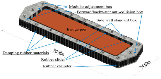
Figure 1.
Plane layout of the new type of UHPC collision avoidance.
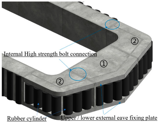
Figure 2.
Device end structure.
2.1.1. Design of No.1 Box
The collision avoidance float tanks on the upstream and backwater surfaces of the bridge piers are both Box No. 1 water distributors with a symmetrical structure that ensures the same protection effect when an upstream or downstream ship impacts a pier. They can reduce part of the additional water mass when a ship hits and turn the bow to change the direction of the impact. The rubber drum outside the box is fixed by a densely reinforced UHPC axle column, which has the characteristics of high strength, good toughness, and excellent durability. Box No. 1 is the main impact box when a ship–bridge collision occurs. Its spatial structure consists of a large number of thin-walled elements. The supporting elements are arranged inside and connected to the UHPC box wall through embedded shear elements. When a ship impacts a box, a large deformation occurs, and the energy dissipation depends on the UHPC box and internal supporting elements. The internal supporting elements include longitudinal braces, diagonal braces, transversal braces, and vertical braces. The cross-sectional dimensions of the longitudinal and diagonal braces are 140 × 140 mm, and the cross-sectional dimensions of the transversal and vertical braces are 200 × 200 mm. The internal structure form is shown in Figure 3.
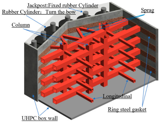
Figure 3.
Internal structure of No.1 box.
2.1.2. Design of No.2 Box
Box No. 2 is a modular adjustment box. Its internal structure is shown in Figure 4. The size of Box No. 2 can be adjusted according to the size of the piers, which is favorable for the popularization and application of UHPC collision avoidances in the future. Rubber drums are assembled on the outside. The cross-sectional dimensions of the internal supporting elements are 200 × 200 mm, and the cross-sectional dimensions of the vertical support are 140 ×140 mm.
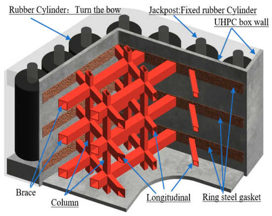
Figure 4.
Internal structure of No.2 box.
2.1.3. Design and Construction of No.3 Box
Box No. 3 is a side wall standard box with a length of 6 m, a width of 2 m and a height of 3 m, which facilitates modular production in factories. The cross-sectional dimensions of the supporting elements inside Box No. 3 are 100 × 100 mm, and its structure is shown in Figure 5.The intermittent rubber sliders between the collision avoidance device and the pier can effectively prevent hard contact damage between the device and the pier, improve the stress concentration phenomenon in the impact area of the pier, prevent partial damage to the pier, increase the impact buffer time, and reduce the impact force, so that the collision avoidance device can better absorb the initial stage of the ship’s impact energy.

Figure 5.
Internal structure of No.3box.
The UHPC collision avoidance device is designed to accommodate the assembly technology. All three types of boxes are factory prefabricated using modular production. They are assembled on site. The process is simple, the construction is rapid, and any damaged floating boxes are easily replaced, all of which can effectively reduce the construction period.
2.2. Finite Element Modeling
This section mainly introduces the finite element model parameters of the collision avoidance device, piers and ships and the contact definitions between the components. For the fluid–solid coupling problem of the collision process, the additional mass method is adopted to consider the influence of the fluid on the collision process. The added mass value of this study is 0.04 times that of the ship’s mass [28].
2.2.1. Finite Element Modeling of UHPC Collision Avoidance Device
The collision avoidance device is modeled by an 8-node solid element SOLID164 arrangement, with a total of 18,907 elements. The reinforcing bars are simulated by link element LINK160, with a total of 44,882 elements, and the internal support elements are modeled by 3-D beam element BEAM161, with a total of 319 elements. Considering that an impact is an instantaneous dynamic response process, the steel bar elements and concrete elements are joined by common nodes in the simulation, without considering the lag of the bond-slip reaction between the steel bars and the concrete. The solid element SOLID164 arrangement is also used to model the rubber drums, the outer rubber damping material, and the inner rubber sliders. To facilitate the modeling and reduce computing time, the rotation of the rubber drums is realized by setting appropriate dynamic and static friction coefficients. The finite element model of the collision avoidance device is shown in Figure 6. The finite element model of the outer wall reinforcement and internal support elements of the buoyancy tank is shown in Figure 7. To simulate the buckling and crushing failure of the UHPC box walls, rubber drums and the inside and outside rubber materials in the finite element model, the * MAT_ADD_EROSION erosion failure criterion [29] is introduced to control the failure of the deformed elements. When the strain on an element is greater than the value set for the failure strain of its material, that element is deleted. Thus, the negative volume phenomenon is avoided. The connections of the UHPC box wall with the inner and outer rubber materials are simplified as common joints. The rubber constitutive model adopts the * MAT_MOONEY-RIVLIN_RUBBER model using values of the density, p = 1600 kg.m−3, Poisson’s ratio, u = 0.4995, and the strain rate parameters C01 = 0.15 MPa and C10 = 0.6 MPa [30].
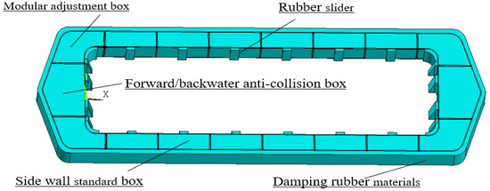
Figure 6.
Finite element model of the collision avoidance device.
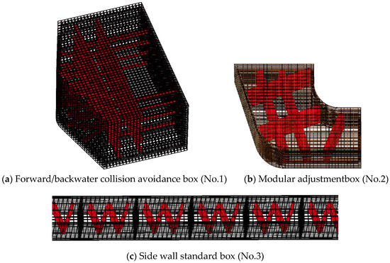
Figure 7.
Finite element model of reinforcement and supporting elements.
The material of the UHPC collision avoidance device adopts the HJC (Holmquist-Johnson-Cook) [31] constitutive model under large strains, high strain rates and high confining pressures. This model takes into account material damage, strain rate, and the influence of the hydrostatic pressure effect on the yield stress. However, there are many parameters in this model and there are no HJC model parameters suitable for the UHPC materials with strain rates corresponding to an impact. Therefore, the research team conducted uniaxial compression, bending, and tension tests, uniaxial cyclic loading and unloading tests, and uniaxial SHPB impact tests on the UHPC materials with strength ratings of C130, and obtained the maximum failure principal strain of 0.01 [32]. By referring to the existing literature [33,34,35], the parameters of the HJC constitutive model of the UHPC material are calculated and analyzed. The parameters are detailed in Table 1.

Table 1.
Calculation parameters of the C130 concrete HJC (Holmquist-Johnson-Cook) constitutive model.
The finite element program ANSYS/LS-DYNA is used to verify the SHPB(Split Hopkinson Pressure Bar) impact test of super high performance concrete, Figure 8 shows the SHPB test setup. The results in Figure 9 show that the equivalent stress, , is highly dependent on the equivalent hydrostatic pressure, . The test and finite element model results are substantially coincident. The rationality and validity of the HJC model parameter measurement method are verified, and the accuracy of the numerical simulations with respect to the performance of the new UHPC collision avoidance device is guaranteed.
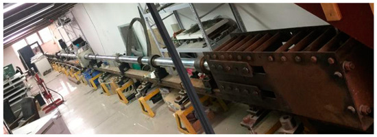
Figure 8.
SHPB (Split Hopkinson Pressure Bar) test device diagram.
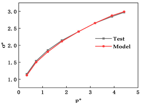
Figure 9.
Comparison of the experimental data with the finite element simulation.
2.2.2. Finite Element Modeling of Piers
In this paper, the selected pier is representative of the #8 pier of the Honghe Bridge, across the Hongwan and Modaomen waterways. The span arrangement of the bridge is (73 + 162 + 500 + 162 + 73) m = 970 m, as shown in Figure 10, The tower height of the pier is 166.5 m, the elevation of the pier cap is −5.5 m, and 24 bored cast-in-place 2.8 m diameter piles are used in the foundation. The eight-node tetrahedral element SOLID164 is used to model the pier. The pier model is divided into upper and lower parts. There are 556,036 elements in total. Using single point Gauss integral and hourglass control, 500 mm is selected as the finest mesh size in the bridge contact area, as shown in Figure 11, and a relatively large mesh size is used to model the parts far away from the contact area. The pier itself has a high stiffness, the deformation of the pier is very insignificant and the influence of the superstructure on the lower structure is negligible in the process of a ship–bridge collision. Therefore, the concrete part above the pier collision area is modeled as a rigid body [36], with a Young’s modulus, E, value of 3.45 × 10⁴ MPa, and a Poisson’s ratio, u, value of 0.2. The pier cap is embedded; thus, the pile foundation is fixed in the form of a foundation. The modeling length is equal to the actual length, which restricts the three-dimensional translational freedom of the element nodes at the pile bottom. The plastic model of the concrete material in the impact zone, which is composed of the failure envelope surface, the hardening cap surface, and the tension cutting limit surface, is the *MAT_GEOLOGIC_CAP model, which can better reflect the material’s nonlinear response under a large strain. Its parameters are shown in Table 2.

Figure 10.
Span layout of the Honghe Bridge in Zhuhai.
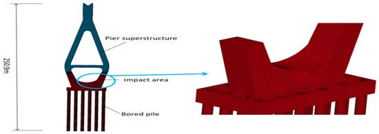
Figure 11.
Finite element model of the pier with the meshed impact zone.

Table 2.
Concrete material parameters of the pier impact zone.
2.2.3. Ship Finite Element Modeling
In this paper, a 5000 DWT river-sea direct cargo ship is selected as the representative ship for the calculations. The ship is divided into two parts, namely the bow and the hull. Since the deformation and failure of the hull are mainly concentrated in the bow of the ship during the impact process, and the hull will not undergo a large plastic deformation or experience a high stress phenomenon [37]. The hull head shell adopts 163 elements to model and accurately simulate the bow, inner keel, deck and bulkhead components according to the actual drawings, totaling 9630 elements. According to the rigid material model, there are 12,647 units. The ship structure and finite element model are shown in Figure 12.
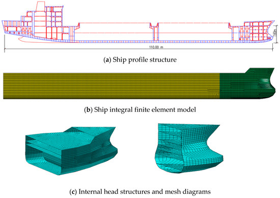
Figure 12.
Ship structure and finite element model.
To ensure a more realistic impact effect, the mesh of the bow impact area is refined, and the minimum element characteristic length is 500 mm. When the equivalent plastic strain of the element exceeds the defined limit plastic strain, a fracture failure of the element will occur. Considering that a collision between a ship and a bridge is a very complex dynamic response process, the following strengthening bilinear plastic model (MAT_PLASTIC_KINEMATIC) is adopted for the bow material and reinforcement of the UHPC box wall. The strain rate [38,39] is considered by the Cowper–Symonds model, and the yield stress is as follows:
where is the dynamic yield stress at the uniaxial plastic strain rate, ε, is the corresponding static yield stress, and the bow material is ordinary low carbon steel with material constants D = 40.4 and q = 5. The equivalent stiffness of the ship model in this study is 12.89 MN/m, which is between of the equivalent stiffness of an inland waterway ship that is equal to 5 MN/m and the equivalent stiffness of ocean-going ship that is equal to 15 MN/m in the European Code, reflecting the accuracy of the ship modeling.
2.2.4. Contact Definition
The ship–bridge collision process is a crushing process in which the collision contact is very complex and important. In this study, the collision process is mainly divided into three stages. First, the bow comes into contact with the device, and moves together with it to the pier during the initial stage of the collision to dissipate part of the energy. In the intermediate stage, the device relies on the UHPC floating box and the supporting elements for large plastic deformation and energy dissipation. In the last stage, the concrete crushes and breaks, and the internal supporting elements buckle. In the simulation, each solid element disappears after its concrete reaches the failure strain, which increases the contact between the bow and steel bars, supporting elements and other components. To accurately simulate the contact problem between the components, the automatic contact algorithm in ANSYS/LS-DYNA is used. This contact algorithm can automatically check the contact between the surfaces in the analysis to determine the actual contact situation and the direction of the shell elements. The automatic face-to-face contact algorithm defined between the ship and the rubber damping material, the ship and the concrete box wall, the ship and the pier, the ship and the pre-embedded shear components, and a box and another box is named *CONTACT_AUTOMATIC_SURFACE_TO_SURFACE. This contact is very effective when the contact area is large and the shape is irregular, and there is a large amount of relative slipping between objects. The automatic point-to-face contact algorithm, * CONTAT_AUTOMATIC_NODES_TO_SURFACE is defined as being between the ship and the support element, the ship and the steel bars, the support element and the pier, the steel bars and the pier, and the support elements and the rubber material. The large deformation experienced in a ship–bridge collision may cause contact between the bow steel elements themselves and the contact position is not fixed. Therefore, an automatic one-sided contact algorithm *CONTACT_AUTOMATIC_SINGLE_SURFACE is defined to detect all contacts during the collision. Table 3 summarizes the main contact pairs during the ship–bridge collision. The dynamic and static friction coefficients between steel contact surfaces are 0.3 [40], and these coefficients between the ship and the rubber material, rubber material and pier are 0.13 [41].

Table 3.
Contact Definition of a Cargo Ship Impact Collision avoidance Floating Tank System.
3. Performance Analysis of Design Parameters
In this section, the following main factors affecting the performance of the collision avoidances are analyzed and optimized: (1) the materials of the internal supporting elements, (2) the thickness of the UHPC box wall, and (3) the reinforcement ratio of the UHPC box wall. The research team is equipped with icore8 desktop computer with AMD ryzen 53600x CPU. When the calculation step is set to 5.87 × 10⁻⁷ s, one workstation can calculate at most three working conditions at the same time, and the file size of the calculation result is about 14.8 GB, which takes 15 days (about 360 h) for one calculation. Due to the heavy computational work and the long computing time, the most seriously damaged and the most concerned forward impact conditions are selected as the main analysis objects in the parameter analysis process, and the sensitivity analysis of a single factor change is carried out. Because of the comparison of the simplified parameters, the collision forces between the parameters are not necessarily calculated under the same reference model. The forward collision condition is a 5000 DWT river–sea direct cargo ship impacting the pier or the collision avoidance device at 5 m/s without a deviation angle. The optimal performance parameters of the collision avoidance device are optimized by energy analysis and force analysis of the ship, the device, and the pier.
3.1. Analysis of Material Properties of Internal Support Elements of Floating Tank
In the preliminary design of the collision avoidance device, three kinds of supporting element materials are proposed, namely, the UHPC material, a low-carbon steel material and a high-strength aluminum alloy material. In this section, the finite element performance analysis of the collision avoidance device with the three different supporting materials is carried out: Condition A1: the supporting element is made of the UHPC material, Condition A2: the supporting element is made of the low-carbon steel material, Condition A3: the supporting element is made of the high strength aluminum alloy.
The system energy curves for Conditions A1, A2, and A3 are shown in Figure 13, Figure 14 and Figure 15. The total energy of the system is defined as the sum of the kinetic energy, internal energy, slip energy and hourglass energy. The total energy of the system is 89.49 MJ in the collision process, which satisfies the Energy conservation law. The internal energy values of the system are 50.03 MJ, 61.60 MJ, and 58.59 MJ for Conditions A1, A2, and A3, respectively, and the hourglass energy values are 3.29 MJ, 3.26 MJ and 3.06 MJ, respectively. The hourglass energy accounts for 6.6%, 5.3%, and 5.2% of the system internal energy, respectively. The hourglass energy accounts for no more than 10% of the system internal energy, which shows that the calculation results are reliable [42].
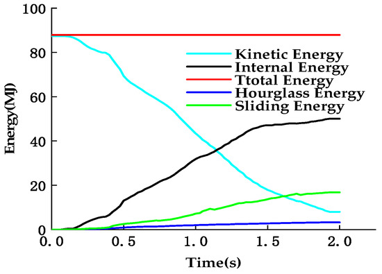
Figure 13.
Energy diagram of the UHPC supporting.
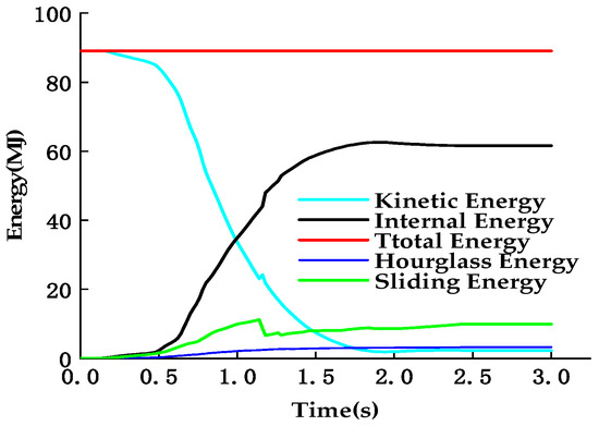
Figure 14.
Energy diagram of the steel supporting.
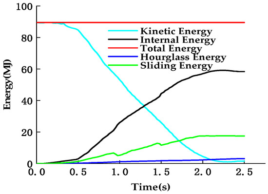
Figure 15.
Energy diagram of aluminum alloy supporting.
The time-history curve of the bow collision depth is shown in Figure 16 in which, for the three conditions, a small drop can be seen after the curves reach their maximum values. The main reason for this is that the maximum plastic deformation of the bow is accompanied by a smaller elastic deformation during the collision process. The maximum collision depth of the bow with the UHPC support elements is 1.42 m, which is 53.6% lower than that of an unprotected condition (3.06 m), while the maximum collision depth of the bow with the steel support element is 1.21 m, which is 60.5% lower than that of the unprotected condition, and the maximum collision depth of the bow with the aluminum alloy support element is 1.61 m, which is 47.4% lower than the maximum bow collision depth of the unprotected condition. It can be seen that the collision depth of the bow is significantly reduced under all three conditions, which proves that the collision avoidance device has excellent protection performance for ships. When the supporting element uses the steel support, the system kinetic energy is converted into internal energy with the largest amplitude and the smallest bow collision depth, indicating that the plastic deformation of the bow absorbs the least amount of energy, and the system kinetic energy is more transformed into the internal energy of the collision avoidance device, which is more favorable as it reduces the depth of the ship’s impact and protects the ship.
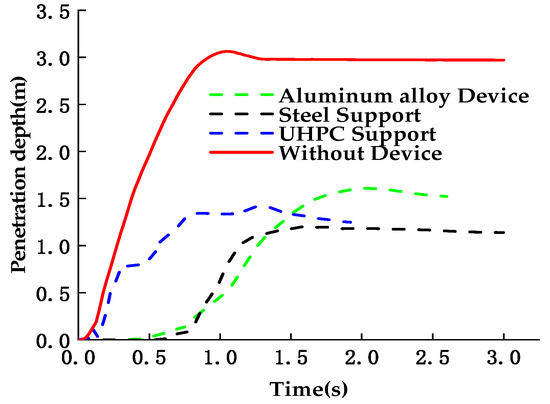
Figure 16.
Bow impact depth time-history curve.
The maximum equivalent stress values on the pier under Conditions A1, A2 and A3 are 42.4 MPa, 38.2 MPa and 39.3 MPa is shown in Figure 17, respectively, which are 32.7%, 39.4% and 37.6% lower than the maximum equivalent stress (63.0 MPa) of the unprotected condition, respectively. It can be seen that the maximum equivalent stress on the pier under Condition A2 is the lowest, because the regional equivalent stress and the protective pier performance are larger and thus weakened the impact on the pier the most.
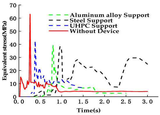
Figure 17.
Equivalent stress curve of the pier impact area.
The time-history curves of the impact force under the three kinds of the collision avoidances and the unprotected condition are shown in Figure 18. The peak value of the impact force under the unprotected condition is 35.30 MN, and the impact duration is only 1.25 s. The main reason is that the rigid contact between the ship and the bridge can complete the energy conversion instantaneously. The impact force time-history curve of Condition A1 decreases rapidly to 2 MN after reaching the peak value of 25.40 MN, and the impact duration is 1.60 s; the impact force peak value of Condition A2 is 21.88 MN, and the impact duration is the longest, reaching 2.56 s, which shows that the deformation buffer effect is the best; when the high strength aluminum alloy supporting element is used, the impact force peak value is 22.82 MN and the impact duration is 2.1 s.
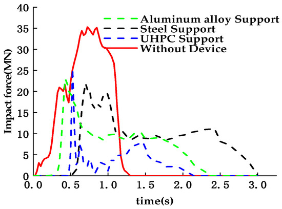
Figure 18.
Impact force time-history curve of the pier.
The performance summary of the collision avoidances under the three protected conditions is shown in Figure 19. All three conditions can reduce the peak impact force, prolong the impact duration at a low impact level, reduce the depth of the ship impact, and reduce the maximum equivalent stress on the pier. This shows that the preliminary design scheme of the collision avoidance device is effective and correct. Especially when the supporting element is in steel, the performance of the collision avoidance device is the most efficient, the peak value of the impact force on the pier is the smallest, the impact duration is the longest, and the energy dissipation capacity is the most prominent, which can significantly reduce the damage to both the ship and the pier. Therefore, a steel supporting element is the best choice among the three materials.
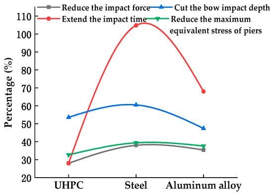
Figure 19.
Collision avoidance performance of the device under different material support elements.
3.2. Performance Analysis of UHPC Floating Tank Wall Thickness Parameters
In view of the fact that this study is based on the Honghe Bridge project in Zhuhai and considering the safety and applicability of the UHPC floating box as well as the economy of the project construction, it is particularly important to determine the thickness of the wall of the new UHPC collision avoidance device. In this section, three different wall thickness parameter, h, values are compared and analyzed: Condition B1: h = 150 mm, Condition B2: h = 120 mm, and Condition B3: h = 90 mm.
In Figure 20, it can be seen that the total energy of the system remains unchanged, which satisfies the law of conservation of energy. The hourglass energy, slip energy, and total energy absorbed by the piers of the system vary little under the three conditions, and all fluctuate over a relatively small range. The slip energy values for Conditions B1, B2, and B3 are 17.7 MJ, 18.9 MJ, and 18.8 MJ, respectively. The slip energy is increased by 40.5%, 50.0% and 49.2%, respectively, compared with the unprotected condition where the slip energy is 12.6 MJ, which indicates that the components of the collision avoidance device produce very large friction energy dissipation during the collision process, which is consistent with reality. The total energy absorbed by the device deformation is obviously less than that absorbed by the device under Conditions B2 and B3. This shows that, when the wall thickness of the UHPC float box is 150 mm, the rigidity of the collision avoidance device is large, the plastic deformation volume of the bow is the largest, the damage deformation is serious, and the flexible energy dissipation performance of the device cannot be fully utilized. Therefore, the energy dissipation performance values of Condition B2 and Condition B3 are better than that of Condition B1 in terms of energy and ship protection.
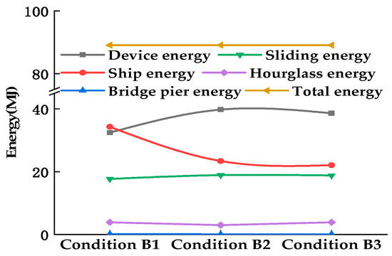
Figure 20.
Energy comparison and summary of the three different wall thicknesses under protected conditions.
From Figure 21 it can be seen that the bow collision depth curves under the three conditions reach their peak values at approximately 1.0 s, which are 1.5 m, 1.40 m, and 1.38 m, respectively. Compared with the bow collision depth value of 3.06 m under the unprotected conditions, the bow collision depth can be reduced by more than 50%. This shows that the collision avoidance device can significantly reduce the bow collision depth to achieve the effect of ship protection.
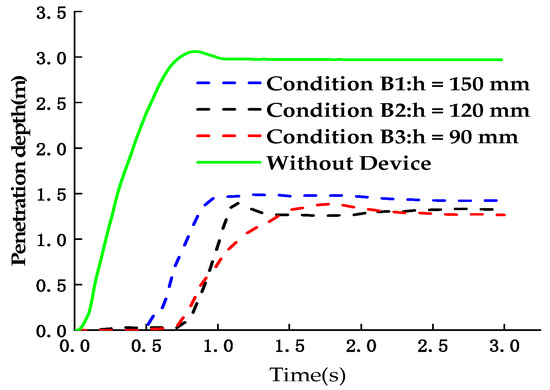
Figure 21.
Bow impact depth time-history curve.
Figure 22 presents the equivalent stress curves on the pier during the ship–bridge collision and shows that the maximum equivalent forces on the piers under the three conditions are 38.2 MPa, 32.9 MPa and 48.9 MPa. Under the three conditions of the collision avoidance device, the maximum equivalent stress on the pier decreases greatly and the curve changes more smoothly, which shows that the device can play a good cushioning and energy dissipation role, and the rubber slider can improve the stress concentration phenomenon in the impact area and prevent local damage to the pier.
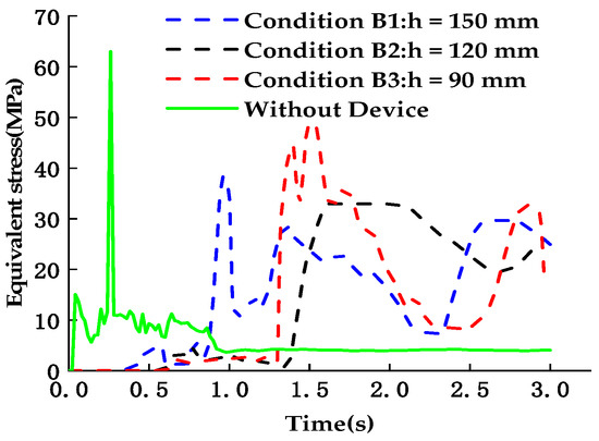
Figure 22.
Equivalent stress curve of the pier impact area.
Figure 23 presents the time-history curves of the impact force on the pier under the three protected conditions and the unprotected condition. It can be seen in this figure that for Condition B1, the peak value of the impact force is 26.27 MN at 2.20 s. The reduction in the impact force is 25.6% while the impact duration is extended by 76%. For Condition B2, the impact force reaches its peak value of 22.5 MN at 0.78 s. The maximum reduction of the impact force is 36.3%. The impact duration is prolonged by 46.4% to 1.83 s. For Condition B3, the peak value of the impact force is 23.26 MN. The impact force is reduced by 34.1%, the impact duration is 1.70 s, and thus, the impact duration is prolonged by 26.5%.
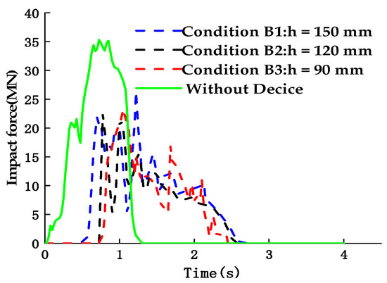
Figure 23.
Impact force time-history curve of the pier.
The performance summary of the collision avoidance device under the three protected conditions is shown in Figure 24. The energy absorption index of the collision avoidance device in this study is synthetically judged by the energy absorbed by the device deformation and the impact force reduction. Considering the reduction of the maximum impact force and the maximum equivalent stress on the pier, Condition B2 is better than Condition B3 in terms of pier protection. At the same time, considering that the UHPC box wall guarantees double-layer bidirectional dense reinforcement and meets the construction requirements of a minimum protective layer thickness in practical engineering, the optimal wall thickness parameter of the collision avoidance device is selected to be that of Condition B2, i.e., a 120 mm wall thickness.
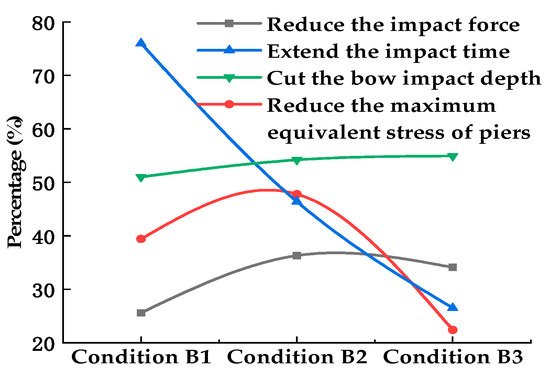
Figure 24.
Collision avoidance performance of the device under different wall thickness.
3.3. Performance Analysis of UHPC Tank Wall Reinforcement Ratio Parameters
Different reinforcement ratios of the collision avoidance device UHPC box wall are simulated numerically. Considering the actual engineering needs, this research mainly includes four conditions: Condition C1: p = 4%, Condition C2: p = 5%, Condition C3: p = 6%, and Condition C4: p = 7%.
The differences due to the reinforcement ratio are mainly reflected in the strength and flexible deformation of the collision avoidance float box. The time-history curves of the bow collision depth under different reinforcement ratios are shown in Figure 25. The changes in the bow collision depth curves under the four conditions are approximately the same. The maximum depth of the bow collision is reached in a short period of time after the impact initiation, and then there is a small rebound. The maximum impact depth of the bow increases with the increase of the reinforcement ratio; however, this is a gradual phenomenon: the maximum impact depths of the bow are 1.47 m and 1.49 m when the reinforcement ratio is 6% and 7%, respectively, and the maximum impact depth of the bow is relatively small (1.21 m) when the reinforcement ratio is 4% and 5%. This shows that the reinforcement ratio of the UHPC box wall is better for the ship protection when reinforcement ratio is 4% and 5%.
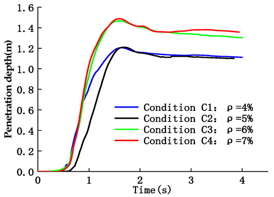
Figure 25.
Bow impact depth time-history curve.
The energy curves of the collision avoidance device under the four conditions are shown in Figure 26. The trends of the collision avoidance device energy curves under the four conditions are similar, reaching their peak values at approximately 1.6 s, then decreasing slightly and tending to stabilize at approximately 2.2 s. This is due to the elastic deformation and energy absorption of the collision avoidance device during the initial stage of the impact and some elastic deformation that occurs after the impact. When the reinforcement ratio is 5%, the maximum absorbed energy of the collision avoidance device is 26.3 MJ, and the plastic deformation energy is 24.6 MJ after stabilization. The difference between them is 1.7 MJ, which is only approximately 6.9% of the plastic deformation energy of the device. It can be seen that the main absorbed energy of the collision avoidance device is the plastic deformation of the device. When the reinforcement ratio is 6%, the deformation absorption of the collision avoidance device is mainly caused by the plastic deformation of the device. The plastic deformation energy is 15.87 MJ after stabilization.
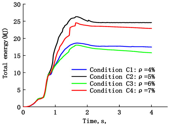
Figure 26.
Energy curves of the collision avoidance device.
In Figure 27, the time-history curves of the impact force under the four working conditions are given. It can be seen in this figure that the peak values of the impact force under Conditions C1, C2 and C3 are obviously smaller than those under Condition C4. At the same time, the peak values of the impact force under these three conditions are 27.5%, 31.6%, and 30.9%, respectively. A double-layer and two-way reinforcement arrangement can directly affect the overall strength of the collision avoidance floating box. When the reinforcement ratio is 7%, the rigidity of the floating box is the largest, and a larger rigid body displacement occurs in the initial stage of the impact. The peak value of the impact force directly impacting the pier is the largest, reaching 30.73 MN, which does not take full advantage of the plastic energy absorption. Therefore, the device cannot absorb energy during the collision process. The ship kinetic energy is the smallest. At the same time, when the reinforcement ratio is 5%, the peak value of the impact force on pier is the smallest, which is 24.13 MN, and the impact duration, which is 2.60 s, is the longest. This is substantially consistent with the design concept of a flexible the collision avoidance device. When the reinforcement ratio is 6%, the peak value of the impact force on the pier is 24.38 MN and the impact duration is 2.52 s. It can be seen that when the reinforcement ratios are 5% and 6%, the collision avoidance device is more able to reduce the impact force and prolong the impact duration.
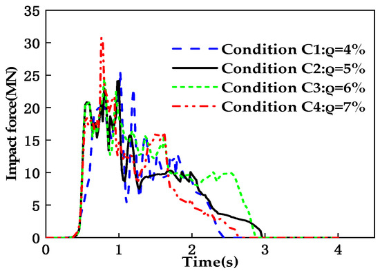
Figure 27.
Impact force time-history curves of pier.
Based on Figure 28, the optimal reinforcement ratio of the collision avoidance device is determined to be 5% by synthesizing the impact depth of the ship, the maximum impact force on the pier and the extension of the impact duration under the four protected conditions compared with the unprotected condition.
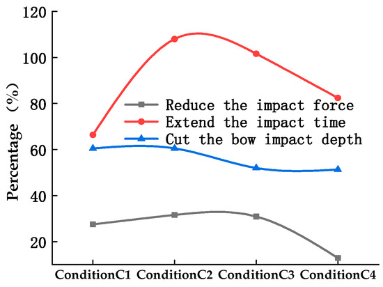
Figure 28.
Collision avoidance performance of device.
4. Research on Performance of Collision Avoidance Device under Optimal Parameters
The performance of the new type of assembled UHPC collision avoidance device is synthetically determined. The wall thickness of UHPC box is 120 mm, the reinforcement ratio is p = 5%, and the combination of internal steel supporting elements is selected. In this section, numerical simulations carried out for the 0° condition, the 15° condition oblique collision, and the 30° Condition oblique collision are compared and analyzed. The calculation steps of both the protected and unprotected conditions are 5.87 × 10⁻⁷ s.
The collision angle, position, and overall deformations of the collision avoidance device under the three conditions are shown in Figure 29, Figure 30 and Figure 31 Under the forward and oblique collision conditions, the collision deformations are mainly concentrated in the UHPC floating box in direct contact with the bow, and this floating box and its internal supporting elements are completely destroyed. Under the 15° condition, an oblique collision, the collision avoidance device produces a counterclockwise torsion around the pier. The forces on the corner of the device are complex in the high stress area, which is consistent with the actual situation, but there is no obvious damage to the outer rubber damper. The outer rubber damper material can easily redirect the ship away from the pier. The ship retains most of its initial kinetic energy, and effectively protects the pier and the bow. Under the three conditions, no large plastic deformation occurred in the nonimpacted UHPC floating boxes. The device maintains good integrity and can continue to be used after one pier impact. At the end of the collision, the cumulative plastic deformation of the collision avoidance float box in the impact area is large, which indicates that the new collision avoidance device conforms to the design concept of absorbing the collision kinetic energy of the ship to reduce the collision force through large plastic deformation.

Figure 29.
0° collision when the ship collides with the collision avoidance device.

Figure 30.
15° collision when the ship collides with the collision avoidance device.

Figure 31.
30° collision when the ship collides with the collision avoidance device.
The process of deformation and stress nephogram of the collision avoidance device at 0° forward collision is shown in Figure 32. From Figure 32 it can be clearly observed that the damage or failure of the collision avoidance device during collision mainly occurs in the floating box directly impacted by the ship, which is a high stress area; however, the other floating boxes far from the impact contact area do not experience large plastic deformations. There are stress concentrations in the connecting areas between the upper and lower roof and the front roof of Box No. 1. The failure disappears after reaching the ultimate failure strain, and the direct contact between the front roof and the bow results in a complete depression deformation, but not complete failure. This proves that the two-layer and two-way reinforcement can give the superhigh performance reinforced concrete roof greater plastic deformation ability. The stress change in the connection area between Box No. 1 and Box No. 2 is more obvious, mainly because the high-strength bolt connections between the boxes body are simplified to common joints and the number of bolts is small, which can better reduce the interaction between the floating tanks, ensuring that individual floating tanks can be assembled separately after failure, and reduce maintenance costs.

Figure 32.
Deformation and stress nephogram of the collision avoidance device at 0° forward collision.
Figure 33 shows the deformation and equivalent stress diagram of the floating box steel support member under the condition of 0 ° frontal collision. It can be seen that the buckling deformation of the frame type steel support elements is large, which has a high plastic deformation energy absorption effect. At 0.6 s (initial impact), the impact effect of the stressed transverse brace and the node has higher equivalent stress, but as the equivalent stress is transferred to the whole frame support, the equivalent stress level in each member decreases, then the transverse brace and longitudinal brace begin to buckle, and the transverse brace begins to buckle first compared with the longitudinal brace, and finally the whole frame support element produces larger deformation, so as to absorb the collision kinetic energy of the ship.
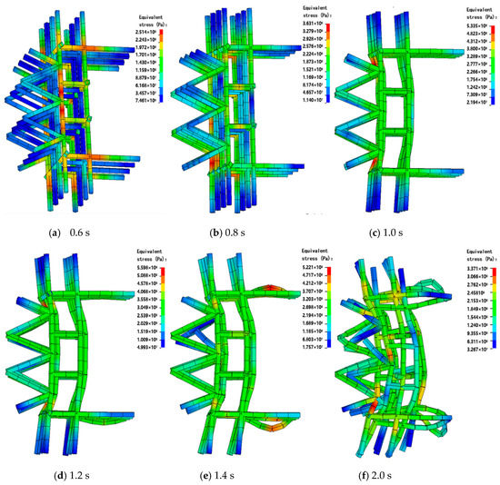
Figure 33.
Deformation and Equivalent stress nephogram of the supporting element at 0° forward collision.
According to the comparison of the ship energy presented in Figure 34, showing a forward collision with or without an collision avoidance device at 0 degrees, it can be seen that the ship deformation and internal energy under the protected condition is 36.6 MJ, which is 51.3% less than that under the unprotected condition and can significantly reduce the deformation energy during a collision, thus achieving the effect of ship protection.
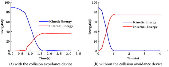
Figure 34.
Ship energy diagram at 0° forward collision.
Comparing the impact forces under the three selected impact angles in the protected and unprotected structure, as shown in Figure 35, the impact force curves have significant nonlinear fluctuation characteristics. Each peak value and the unloading of the impact force curve represent the stress-strain wave transmission during the impact process, which causes the failure or damage to the ship or a part of the collision avoidance device.
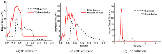
Figure 35.
Time history curve of impact force of piers under different collision angles.
5. Discussion
The results of the impacts under the three conditions and the calculated values of the impact forces under the different specifications are summarized in Table 4. From Table 4, the following rules can be found: the deviation of the impact force between the numerical simulation results of the collision avoidance device under the forward collision 0° Condition and calculation results based on JTG D60-2015 [43], TB10002-2017 [44], AASHTO [45], and Eurocode [46] are 3.1%, 103%, 16.8%, and 30.3%, respectively. The large deviation of the impact force calculated based on "Code for Design of Railway Bridges and Culverts" is mainly due to the small kinetic energy reduction coefficient gamma and the difficulty in mastering the elastic deformation coefficients, C1 and C2, in the empirical formula. The results show that the impact force calculated based on the "General Specification for Highway Bridge and Culvert Design" is in good agreement with the numerical simulation results.

Table 4.
Summary of the impact results under the three conditions and the different specifications.
For the Honghe Bridge in Zhuhai, the design resistance of the pier is 27.2 MN, and the maximum impact force without the collision avoidance device is 35.31 MN, which exceeds the design resistance by 30.0%, seriously endangering the safety of the bridge. However, the maximum impact force with the collision avoidance device decreases to 20.57 MN, which is lower than the design resistance by 24.4%, effectively protecting the bridge structure.
It can be seen that this newly assembled UHPC collision avoidance device has good energy absorption performance and design performance. Moreover, the size of the longitudinal and transverse direction of the collision avoidance device can be adjusted by setting the number of floating tanks of different specifications to serve as the collision avoidance protection structure of different types of piers, which provides an important reference for future bridge construction safety.
6. Conclusions
The performance of the new type of assembled UHPC collision avoidance device is analyzed by the finite element numerical simulation method. The following conclusions are drawn:
- (1)
- The new type of assembled UHPC collision avoidance device proposed in this paper consists of three types of modular collision avoidance floating boxes and intermittent rubber sliders. Each collision avoidance floating box is composed of rubber drums, rubber damper material, a double-layer, double-direction, densely reinforced, and super high-performance concrete shell structure, and steel supporting elements. This device can take full advantage of its plastic deformation, strong energy absorption, excellent corrosion resistance and durability, modular production and assembly, high efficiency of on-site installation, convenient replacement of damaged floating boxes, and low maintenance cost.
- (2)
- The newly assembled UHPC collision avoidance device can significantly reduce the maximum impact force and extend the impact duration of the pier in a ship–bridge collision. For the forward collision conditions, which occur frequently and result in serious damage in engineering practice, the peak impact force acting on the pier can be reduced by 41.8%, the impact duration can be extended by 100.0%, and the damage deformation energy to the bow can be reduced by 34.6%. The collision avoidance device can protect bridge piers and ships efficiently.
- (3)
- The damage to and deformation of the collision avoidance device itself is mainly concentrated in any of the floating boxes directly impacted by the ship, the rubber drums on the external side of the floating boxes, and the rubber sliders on the internal side. The other, not directly impacted, floating boxes will not undergo damage or deformation.
- (4)
- The new collision avoidance device has good collision avoidance and energy dissipation performance, which mainly comes from the UHPC floating boxes that have double-layer two-way dense reinforcement and the internal steel supporting elements. The floating box wall can take full advantage of its strength to improve the overall strength of the device. The internal supporting elements fully absorb the impact kinetic energy by elastic-plastic deformation and buckling. The discontinuous rubber sliders on the internal side of the collision avoidance device can improve the hard contact environment between the device and the pier, and significantly reduce the peak impact force of the pier.
- (5)
- Because of its reasonable design and layout, the internal steel support has a high flexibility and viscous energy dissipation response during the impact process of 5000 DWT ships, so it can be used as a flexible energy dissipation and impact resistance component, especially under impact conditions, and has good economic application prospects.
Only finite element results are presented in this paper. The results are to be confirmed by experimental investigation.
Author Contributions
Conceptualization, L.Z., H.L., J.W., X.P., A.D.M. and L.J.; methodology, L.Z., H.L. and X.P.; software, L.Z., H.L., J.W., X.P., A.D.M., L.J.; validation, L.Z., H.L. and X.P.; formal analysis, L.Z., H.L., J.W., X.P. and D.H.; investigation, L.Z., H.L., J.W., X.P. and D.H.; resources, H.L., J.W., X.P., A.D.M. and L.J.; data curation, L.Z., H.L., J.W., X.P., A.D.M., L.J. and D.H.; writing—original draft preparation, L.Z., H.L., J.W., X.P., A.D.M. and L.J.; writing—review and editing, L.Z., H.L. and J.W.; supervision, L.Z., H.L., J.W., X.P., A.D.M. and L.J.; project administration, L.Z., H.L., J.W., X.P., A.D.M., L.J. and D.H.; funding acquisition, L.Z., H.L., J.W., X.P., A.D.M. All authors have read and agreed to the published version of the manuscript.
Funding
This research was funded by the National Natural Science Foundation of China, grant number 51578546, 51878674 and U1934217; the National Science Joint High-Speed Railway Foundation of China, grant number U1434204; and Project(2020zzts157) supported by the Fundamental Research Funds for the Central Universities of Central South University.
Acknowledgments
The authors would like to thank Huang Dunwen for the design of the dimensions of the collision avoidance device and Liu Kang who provided the constitutive model parameter test support.
Conflicts of Interest
The authors declare no conflicts of interest.
References
- Xia, C.Y.; Ma, Q.; Song, F.D.; Wu, X.; Xia, H. Dynamic analysis of high-speed railway train-Bridge system after barge collision. Struct. Eng. Mech. 2018, 67, 9–20. [Google Scholar] [CrossRef]
- Larsen, O.D. Ship Collision with Bridges, the Interaction between Vessel Traffic and Bridge Structures; IABSE: Zuerich, Switzerland, 1993. [Google Scholar]
- Gholipour, G.; Zhang, C.W.; Mousavi, A.A. Nonlinear numerical analysis and progressive damage assessment of a cable-stayed bridge pier subjected to ship collision. Mar. Struct. 2020, 69, 102662. [Google Scholar] [CrossRef]
- Jiang, L.Q.; Ye, J.H.; Zheng, H. Collapse mechanism analysis of the FIU pedestrian bridge based on the improved structural vulnerability theory (ISVT). Eng. Fail. Anal. 2019, 104, 1064–1075. [Google Scholar] [CrossRef]
- Jiang, L.Q.; Ye, J.H. Redundancy of a mid-rise CFS composite shear wall building based on seismic response sensitivity analysis. Eng. Struct. 2019, 200, 109647. [Google Scholar] [CrossRef]
- Jiang, L.Q.; Ye, J.H. Collapse Mechanism and shaking table test validation of a 3D mid-rise CFS composite shear wall building. Thin Walled Struct. 2020, 146, 106470. [Google Scholar] [CrossRef]
- Wang, J.J.; Song, Y.C.; Wang, W.; Chen, C.J. Evaluation of flexible floating anti-collision device subjected to ship impact using finite-element method. Ocean. Eng. 2019, 178, 321–330. [Google Scholar] [CrossRef]
- Toyama, Y. Drift-wood collision load on bow structure of high-speed vessels. Mar. Struct. 2009, 22, 24–41. [Google Scholar] [CrossRef]
- Rong, Z.D.; Sun, W.; Zhang, Y.S. Dynamic compression behavior of ultra-high performance cement based composites. Int. J. Impact. Eng. 2010, 37, 515–520. [Google Scholar] [CrossRef]
- Bragov, A.M.; Petrov, Y.V.; Karihaloo, B.L.; Konstantinov, A.Y.; Lamzin, D.A.; Lomunov, A.K.; Smirnov, I.V. Dynamic Strengths and Toughness of an Ultra High Performance Fibre Reinforced Concrete. Eng. Fract. Mech. 2013, 110, 477–488. [Google Scholar] [CrossRef]
- Millard, S.G.; Molyneaux, T.C.K.; Barnetts, S.J.; Gao, X. Dynamic Enhancement of Blast-resistant Ultra High Performance Fibre-reinforced Concrete Under Flexural and Shear loading. Int. J. Impact. Eng. 2010, 37, 405–413. [Google Scholar] [CrossRef]
- Graybeal, B.A.; Tanesi, J. Durability of an ultra high performance concrete. J. Mater. Civil. Eng. 2007, 19, 848–854. [Google Scholar] [CrossRef]
- Reju, R.; Jacob, G.J. Investigations on the Chemical Durability Properties of Ultra High Performance Fibre Reinforced Concrete. In Proceedings of the 2012 International Conference on Green Technologies (ICGT), Trivandrum, India, 18–20 December 2012. [Google Scholar]
- Hoang, A.L.; Fehling, E. Assessment of stress-strain model for UHPC confined by steel tube stub columns. Struct. Eng. Mech. 2017, 63, 371–384. [Google Scholar]
- Wan Yl Zhu, L.; Fang, H.; Liu, W.Q.; Mao, Y.F. Experimental testing and numerical simulations of ship impact on axially loaded reinforced concrete piers. Int. J. Impact. Eng. 2019, 125, 246–262. [Google Scholar]
- Consolazio, G.R.; Cook, R.A.; McVay, M.C. Barge Impact Testing of the St. George Island Causeway Bridge, Phase III: Physical Testing and Data Interpretation; University of Florida: Gainesville, FL, USA, 2006. [Google Scholar]
- Chu, L.M.; Zhang, L.M. Centrifuge modeling of ship impact loads on bridge pile foundations. J. Geotech. Geoenviron. 2011, 137, 405–420. [Google Scholar] [CrossRef]
- Zeng, L.; Xiao, Y.; Chen, Y.; Jin, S.; Xie, W.; Li, X. Seismic Damage Evaluation of Concrete-Encased Steel Frame-Reinforced Concrete Core Tube Buildings Based on Dynamic Characteristics. Appl. Sci. 2017, 7, 314. [Google Scholar] [CrossRef]
- Zhu, L.; Liu, W.Q.; Fang, H.; Chen, J.Y.; Zhuang, Y.; Han, J. Design and simulation of innovative foam-filled Lattice Composite Bumper System for bridge protection in ship collisions. Compos. Part B Eng. 2019, 157, 24–35. [Google Scholar] [CrossRef]
- Consolazio, G.R.; Cowan, D.R. Nonlinear analysis of barge crush behavior and its relationship to impact resistant bridge design. Comput. Struct. 2003, 81, 547–557. [Google Scholar] [CrossRef]
- Kameshwar, S.; Padgett, J.E. Response and fragility assessment of bridge columns subjected to barge-bridge collision and scour. Eng. Struct. 2018, 168, 308–319. [Google Scholar] [CrossRef]
- Song, Y.C.; Wang, J.J. Development of the impact force time-history for determining the responses of bridges subjected to ship collisions. Ocean. Eng. 2019, 187, 106182. [Google Scholar] [CrossRef]
- Sha, Y.Y.; Hao, H. Laboratory tests and numerical simulations of barge impact on circular reinforced concrete piers. Eng. Struct. 2013, 46, 593–605. [Google Scholar] [CrossRef]
- Korucu, H. Polypropylene fiber reinforced concrete plates under fluid impact. Part II: Modeling and simulation. Struct Eng. Mech. 2016, 60, 225–235. [Google Scholar] [CrossRef]
- Wang, P.F.; Zhang, X.; Zhang, H.; Li, X.T.; He, P.G.; Lu, G.X.; Yu, T.X.; Yang, J.L. Energy absorption mechanisms of modified double-aluminum layers under low-velocity impact. Int. J. Appl. Mech. 2015, 7, 1550086. [Google Scholar] [CrossRef]
- Travanca, J.; Hao, H. Numerical analysis of steel tubular member response to ship bow impacts. Int. J. Impact. Eng. 2014, 64, 101–121. [Google Scholar] [CrossRef]
- Xu, G.; Wang, Y.; Du, Y.; Zhao, W.; Wang, L. Static Strength of Friction-Type High-Strength Bolted T-Stub Connections under Shear and Compression. Appl. Sci. 2020, 10, 3600. [Google Scholar] [CrossRef]
- Song, M.; Kim, E.; Amdahl, J.; Ma, J.; Huang, Y. A comparative analysis of the fluid-structure interaction method and the constant added mass method for ice-structure collisions. Mar. Struct. 2016, 49, 58–75. [Google Scholar] [CrossRef]
- Hallquist, J.O. LS-DYNA Keyword User’s Manual; Livermore Software Technology Corporation: Livermore, CA, USA, 2013. [Google Scholar]
- Zhou, L.Y.; Pu, X.X.; Wei, J. Precast UHPC protection system for bridge pier against ship collision. J. Cent. South Univ. (Sci. Technol.) 2019, 50, 923–930. [Google Scholar]
- Kong, X.Z.; Fang, Q.; Wu, H.; Peng, Y. Numerical predictions of cratering and scabbing in concrete slabs subjected to projectile impact using a modified version of HJC material model. Int. J. Impact. Eng. 2016, 95, 61–71. [Google Scholar] [CrossRef]
- Liu, K. Experimental study on Dynamic Constitutive Model of Ultra-High Performance Concrete. Master’s Thesis, Central South University, Changsha, China, 2019. [Google Scholar]
- Tai, Y.S. Flat ended projectile penetrating ultra- high strength concrete plate target. Theor. Appl. Fract. Mec. 2009, 51, 117–128. [Google Scholar] [CrossRef]
- Xie, B.J.; Yan, Z.; Du, Y.J.; Zhao, Z.M.; Zhang, X.Q. Determination of Holmquist-Johnson-Cook Constitutive Parameters of Coal: Laboratory Study and Numerical Simulation. Processes 2019, 7, 386. [Google Scholar] [CrossRef]
- Holomquist, T.J.; Johnson, G.R.; Cook, W.H. A computational constitutive model for concrete subjective to large strains, high strain rates, and high pressures. In Proceedings of the 14th International Symposium on Ballistics, Quebec City, QC, Canada, 26–29 September 1993. [Google Scholar]
- Sha, Y.Y.; Hao, H. Nonlinear finite element analysis of barge collision with a single bridge pier. Eng. Struct. 2012, 41, 63–76. [Google Scholar] [CrossRef]
- Fan, W.; Yuan, W.C. Numerical simulation and analytical modeling of pile-supported structures subjected to ship collisions including soil-structure interaction. Ocean Eng. 2014, 91, 11–27. [Google Scholar] [CrossRef]
- Kang, H.; Kim, J. Response of a steel column-footing connection subjected to vehicle impact. Struct. Eng. Mech. 2017, 63, 125–136. [Google Scholar]
- Fang, H.; Mao, Y.F.; Liu, W.Q. Manufacturing and evaluation of large-scale composite bumper system for bridge pier protection against ship collision. Compos. Struct. 2016, 158, 187–198. [Google Scholar] [CrossRef]
- Jiang, H.; Geng, B.; Zhang, X.X. A new fender system for bridge pier protection against vessel collision. J. Vib. Shock. 2014, 33, 154–160. [Google Scholar] [CrossRef]
- Pu, X.X. Research on Ship-bridge Collision and Precast UHPC Anti-collision Device. Master’s Thesis, Central South University, Changsha, China, 2019. [Google Scholar]
- Shang, X.J.; Su, J.Y. ANSYS/LS-DYNA Dynamic Analysis Method and Engineering Example; China Water & Power Press: Beijing, China, 2005. [Google Scholar]
- General Specifications for Design of Highway Bridges and Culverts (JTG D60—2015); China Communications Press Co. Ltd.: Beijing, China, 2015.
- Code for Design on Railway Bridge and Culvert (TB10002—2017); China Railway Publishing House: Beijing, China, 2017.
- Guide Specifications and Commentary for Vessel Collision Design of Highway Bridges (AASHTO); American Association of State Highway and Transportation Officials: Washington, DC, USA, 2009.
- Vrouwenvelder, A.C. Design for Ship Impact According to Eurocode 1 part 2.7, Ship Collision Analysis; TNO Bouw: Rotterdam, The Netherlands, 1998. [Google Scholar]
© 2020 by the authors. Licensee MDPI, Basel, Switzerland. This article is an open access article distributed under the terms and conditions of the Creative Commons Attribution (CC BY) license (http://creativecommons.org/licenses/by/4.0/).