Article

Concentrating Solar Collectors for a Trigeneration System—A Comparative Study

by
Evangelos Bellos
* and
Christos Tzivanidis
Thermal Department, School of Mechanical Engineering, National Technical University of Athens, Zografou, Heroon Polytechniou 9, 15780 Athens, Greece
*
Author to whom correspondence should be addressed.
Appl. Sci. 2020, 10(13), 4492; https://doi.org/10.3390/app10134492
Submission received: 12 June 2020 / Revised: 25 June 2020 / Accepted: 28 June 2020 / Published: 29 June 2020

Abstract

:
The objective of this study is the investigation of different solar concentrating collectors for application in a trigeneration system. Parabolic trough collectors, linear Fresnel reflectors and solar dishes are the examined solar concentrating technologies in this work. The trigeneration unit includes an organic Rankine cycle coupled with an absorption heat machine that operates with LiBr/water. The analysis is performed throughout the year by using the weather data of Athens in Greece. The results of this work indicate that the selection of parabolic trough collectors is the best choice because it leads to the maximum yearly system energy efficiency of 64.40% and to the minimum simple payback period of 6.25 years. The second technology is the solar dish with the energy efficiency of 62.41% and the simple payback period of 6.95 years, while the linear Fresnel reflector is the less efficient technology with the energy efficiency of 35.78% and with a simple payback period of 10.92 years. Lastly, it must be stated that the thermodynamic investigation of the system is performed with a created model in Engineering Equation Solver, while the dynamic analysis is performed with a code in the programming language FORTRAN.

1. Introduction

Solar irradiation exploitation is an effective weapon in order to face critical issues such as population growth which leads to higher energy consumption [1], the need for sustainable energy systems [2] and various environmental problems related to greenhouses emissions [3]. Concentrating solar power is an efficient way to produce high quantities of useful heating at various temperatures in order to fulfill the energy needs of numerous applications such as space-heating, industrial-heating, air-conditioning, refrigeration, electricity, desalination, industrial heat and methanol-reforming [4], while a lot of interest exists in hybrid solar concentrating systems [5]. The cogeneration [6] and the trigeneration systems [7] are highly efficient technologies because they produce many useful outputs by utilizing waste heat quantities from one subsystem to another, and so overall there is lower entropy generation. The exploitation of solar energy in order to drive or to assist a trigeneration system seems to be a sustainable choice in order to create efficient systems that are also environmentally friendly [8].
Solar-driven trigeneration systems are usually applied in the building sector which is responsible for a great part of worldwide energy consumption [9]. The building sector needs mainly electricity, heating and cooling; three kinds of energy which are usually produced by the trigeneration configurations. Moreover, it must be stated that the trigeneration systems aid the efficient operation of the utilized devices and the exploitation of solar irradiation reduces fossil fuel consumption and grid electricity consumption. Moreover, it is useful to state that there are extra ways of enhancing the energy behavior of the buildings such as sustainable ventilation strategies [10] and novel architecture techniques [11].
In the literature, the utilization of solar concentrating power for feeding trigeneration systems has been examined by many researchers. Usually, the organic Rankine cycle (ORC) is used as a primary mover, and it is combined with heat pumps which can be vapor-compressors or absorption heat pumps. Al-Sulaiman et al. [12] carried out thermodynamic studies of a solar-fed trigeneration unit with a parabolic trough collector (PTC), absorption machine and ORC. The solar collectors give useful heat in the ORC, and the ORC condenser transfers heat to the absorption heat pump. According to their findings, the system presents exergy efficiency close to 20%. In addition, Bellos and Tzivanidis [13] examined a similar system and they calculated that the optimized configurations present 29.4% exergy efficiency and approximately 150% energy efficiency. The high value of the system energy efficiency is explained by the use of the absorption chiller as a heat transformer in order to exploit the cooling production as the energy input and partially to make heating production. Eisavi et al. [14] carried out a study of a system with an organic Rankine cycle and a double-stage absorption machine, and they found the maximum exergy efficiency to be approximately 13% while the respective energy efficiency is about 95%. Zhao et al. [15] conducted a comparative work of the optimum way for combining an absorption chiller, ORC and parabolic trough collectors. They found that feeding the absorption chiller by the waste heat of the ORC is the best way to achieve a maximum exergy efficiency of around 41%. Khalid et al. [16] examined the use of an absorption chiller and an ORC in the solar field loop. Moreover, there is an assisted vapor compression cycle for heating production which is driven by the ORC waste heat, while geothermal and wind energy are included in this work. They found that the exergetic performance of the unit is 7.3% and the energetic 76.1%, while the system net present value is USD 345,000. Bellos et al. [17] examined a unit with a vapor compression heat pump coupled with an organic Rankine cycle. This system is fed by PTCs and a biomass boiler, while heating is produced in two temperatures (low and medium levels). They calculated the energy and exergy efficiency values at 51.3% and 21.8%, respectively. Moreover, they concluded that the investment is sustainable with a payback period of about 5 years. A comparative study of different configurations of trigeneration systems [18] coupled with a PTC proved that the connection of an absorption chiller in the ORC condenser is the best technique, and the separate use of the ORC and an absorption chiller is the second, while the connection of a vapor cooling compression cycle to the ORC turbine is the less efficient choice. In another work, Dabwan et al. [19] tried to use a PTC in a Brayton–Rankine combined cycle in order to reduce fuel consumption. According to their results, it is found that the cost of the produced power can be 22% lower with the exploitation of the solar irradiation.
The utilization of Linear Fresnel reflectors (LFR) has been examined by Moaleman et al. [20]. More specifically, they examined a system with (LFR) coupled with a thermal photovoltaic absorber for heating and power production. Moreover, this unit included a storage tank, an absorption machine and heat exchanging surfaces. They found that the yearly production of electricity, cooling and heating is 2.29, 3.94 and 6.53 MWh, respectively. Another literature study with an LFR-based trigeneration system has been conducted by Thomas et al. [21]. They designed a system of 45 kW electricity power which also produces heating and cooling, while its main devices are a Rankine power block, absorption chiller, adsorption chiller and cooling towers. Dawban et al. [22] found that the integration of LFR in a Brayton–Rankine combined cycle leads to a levelized cost of electricity close to USD 0.06/kWh, an overall plant efficiency at 80%, and the solar share reaches close to 10%.
The use of solar dishes (SD) has been investigated by Hogerwaard et al. [23] in a unit with a Brayton cycle, an organic Rankine cycle and an absorption machine for desalination, heating and electricity production. They calculated the energy and exergy efficiencies at 28.4% and 27%, respectively, while the daily fresh water production was 1.5 m3 at 70 °C. They compared their system with a Kalina cycle for electricity production, and they generally found similar efficiencies; the Kalina cycle has lower energy efficiency and higher efficiency. However, they stated that the multigeneration system is more efficient because it can cover more energy needs and not only electricity production.
Moreover, in another literary work, El-Emam and Dincer [24] studied a unit with solar dishes and a biomass boiler which includes a Brayton cycle, fuel-cell, absorption chiller and gasifier, while the useful products are cooling, electricity and hydrogen. The energetic and exergetic efficiencies were calculated at 40% and 27%, respectively. Ullvius and Rokni [25] studied a system with solar dishes coupled with the Stirling engine, PTC, solid oxide fuel cell and desalination unit. The useful outputs of this system are hydrogen, fresh water and electricity, while the system energy efficiency is around 19% and the daily water production is 8.5 m3.
Lastly, there are some studies with solar towers in trigeneration systems. Mohammadi and McGowan [26] studied a system with a solar tower, Rankine cycle, absorption chiller, distillation unit and back-up boiler which produces fresh water, electricity and cooling power. According to their results, this trigeneration system presents system energy efficiency at 35%. In another work, with a tower in the trigeneration system, Khalid et al. [27] studied the combination of a Rankine cycle to a Brayton cycle for electricity, heating and cooling production with energy and exergy efficiencies at 67% and 40%, respectively.
The aforementioned literature review demonstrates the great scientific interest in the investigation of solar-driven trigeneration units. The objective of this investigation is the comparison of different solar concentrating technologies in a promising and highly efficient trigeneration system. Parabolic trough solar collectors (PTC), linear Fresnel solar reflectors (LFR) and solar dish collectors (SD) are the studied solar technologies that are applied for the weather data of Athens in Greece. The results are evaluated in energetic and economic terms. More specifically, this work studies, in dynamic conditions, the three most usual solar concentrating collectors for medium- and high-temperature applications (300–400 °C). The results are evaluated in energy, exergy and financial terms in order to perform a multilateral work. According to the literature review of this work, the studies usually select one kind of solar collector and investigate it. To our knowledge, there are no studies that examine and compare different solar concentrating technologies in trigeneration systems in order to determine the most efficient and viable configurations. So, the present work aims to give an answer to the question about the most efficient and most viable scenario by comparing three solar concentrating systems. The selected trigeneration “block” includes an ORC coupled with an absorption chiller. This design is the most efficient, according to the results of reference [18]. The thermodynamic analysis of the unit is conducted by a homemade thermodynamic program in Engineering Equation Solver (EES) [28] and a homemade dynamic code that is developed in the programming language FORTRAN.

2. Materials and Methods

2.1. The Investigated Trigeneration Unit

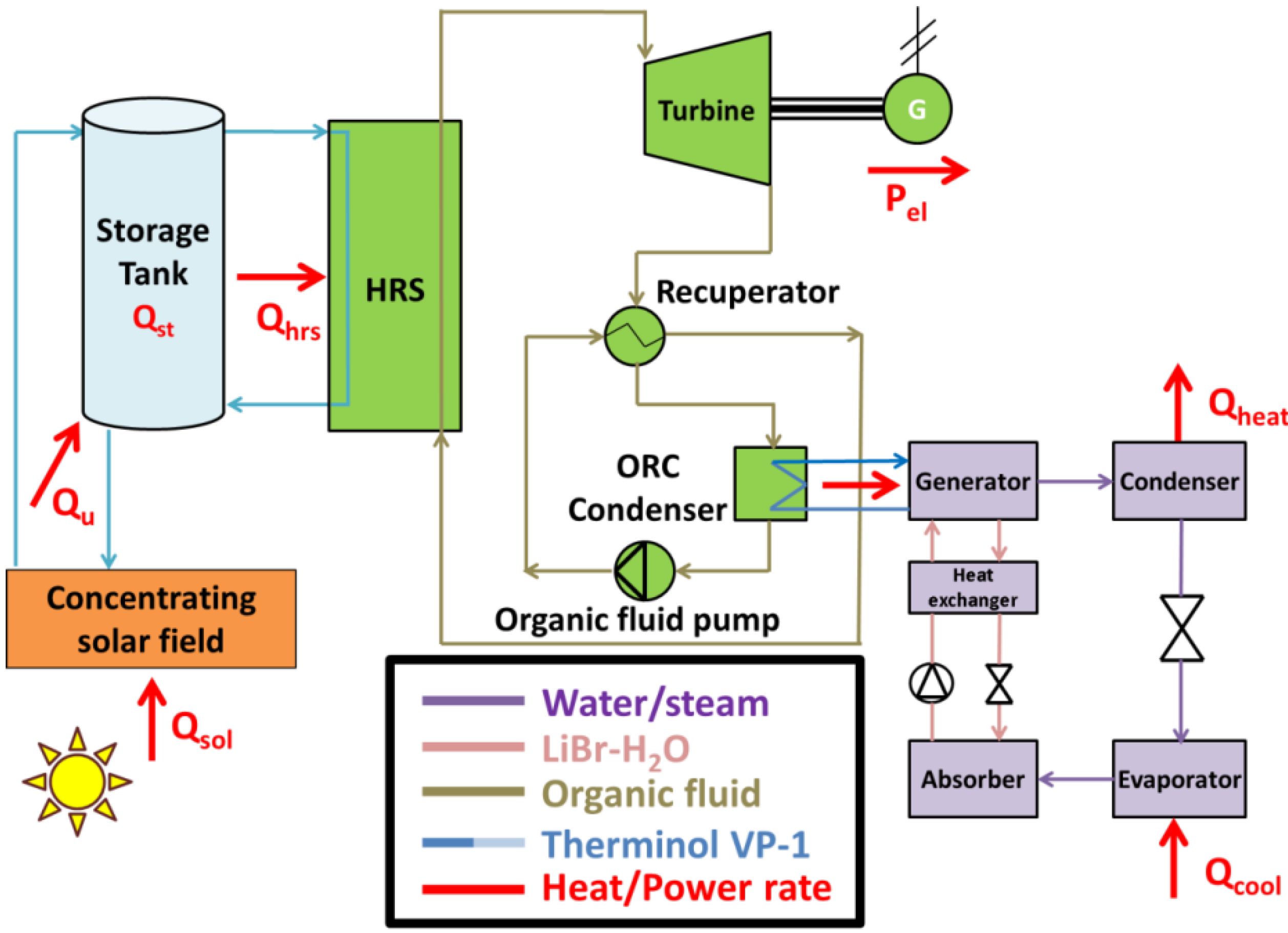
In this paper, a solar-driven trigeneration configuration was examined, and Figure 1 depicts this system. There was an ORC, a single-stage absorption machine, a solar field with PTC and a sensible storage tank device. More specifically, the storage was performed by using an insulated tank which included thermal oil. The ORC is an advantaged technological cycle with a regenerative heat exchanger in order to achieve high efficiency. Generally, the use of a regenerator exploits a part of the waste energy after the turbine, and so it reduces the heat input needs in the heat recovery system. An enhancement of around 5% in efficiency can be achieved with this advantaged configuration in comparison to the simple ORC. The organic fluid was toluene and there was superheating of 20 °C. The pinch point (smallest temperature deviation) in the recuperator was about 10 °C, while in the heat recovery system (HRS) the pinch point was about 5 °C. Typical values were selected for the efficiency values of the turbine and the generator. More specifically, the isentropic efficiency in the turbine was equal to 85% and the electromechanical efficiency in the generator was about 97%.
The single-stage absorption chiller operated with the H2O/LiBr as the working pair. The cooling product was taken by the evaporator device which operated at 5 °C, while the heating was produced by the condenser device which operated at 60 °C. The absorber device rejected the ambient and it operated at 40 °C. The heat exchanger effectiveness was 70% and the generator temperature was selected at 115 °C (after a sensitivity analysis), while the pinch point in the generator was 5 °C. For more details about this system, the reference [13] can be useful. The solar field was 100 m2 in all the cases, and there was a storage tank of 4 m3 [29]. The working fluid was thermal-oil, and more specifically the Therminol VP1, in order to operate up to 400 °C safely [30]. The solar collector mass flow rate was 2 kg s−1, and this value was calculated by using a typical value of 0.02 kg s−1 m−2 for the specific flow rate [31]. The storage tank included thermal oil, and it had a cylindrical shape and a height equal to the diameter. Moreover, the storage tank thermal losses coefficient was about 0.5 W m−2 K−1 [32] which is a reasonable value for an insulated tank. Table 1 summarizes all the aforementioned data of the studied configuration. At this point, it is important to state that the selection of the collecting area in a specific value (100 m2) is an assumption of this work and it determines the plant size because this parameter is associated with the heat input by the sun in the system. The values of nominal electricity, heating and cooling powers are dependent on the heat input value in the system.
In this work, three different solar concentrating technologies were studied, and they are depicted in Figure 2. Parabolic trough collectors and linear Fresnel reflectors are linear concentrating systems that are constructed with their main axis in the south-north direction, while they follow the sun movement with a tracking system in the east-west direction. The solar dish is a focal point concentrating technology that follows the sun with a two-axis system in order to have the sun-rays vertical to each aperture at every moment.
The PTC and the LFR are solar concentrating technologies with many similarities because they are linear concentrating systems. The PTC presented higher optical efficiency than the LFR, while the LFR was a simpler technology at a relatively lower cost. The lower cost of the LFR was justified by the simple tracking mechanism which moved small mirrors close to the ground, while the PTC moved a great reflector. Additionally, the receiver of the LFR was stable at a height of 3 to 5 m, while the PTC receiver moved during its operation. These factors made the wind loads significantly lower for the LFR and so the construction of this system led to a lower cost. However, the simpler design increased the optical losses due to the shading and blocking effects between the primary reflectors, while there were extra optical losses due to the spaces between the primary reflectors and the existence of a secondary reflector over the absorber.

2.2. Main Mathematical Formulation

Below, only the most important equations for the studied system are included in the present section. More details can be found in the reference [13] about the modeling of the ORC and the absorption chiller.
The solar direct beam irradiation levels that the collector receives (Qsol) can be found by the following formula:
Q s o l = A c o l G b .
The collector useful heating production (Qu) can be found by exploiting the next formula:
Q u = η t h , c o l Q s o l .
The available solar beam irradiation on the receiver surface (Qavail) can be estimated by using the next expression:
Q a v a i l = K Q s o l .
The storage tank’s overall energy balance is given by the following equation:
Q s t = Q u Q l o s s Q h r s .
The energy efficiency of the solar-driven trigeneration unit (ηen) is defined as below:
η e n = P e l + Q h e a t + Q c o o l Q s o l .
The exergetic efficiency of the studied unit (ηex) can be calculated according to Equation (6). The exergetic flow rate of the solar beam irradiation was found by applying the Petela formula [33] which is a usual choice for the undiluted solar direct beam irradiation:
η e x = P e l + Q h e a t ( 1 T a m T h e a t ) + Q c o o l ( T a m T c o o l 1 ) Q s o l [ 1 4 3 T a m T s u n + 1 3 ( T a m T s u n ) 4 ] .
In this work, the temperature level of the outer sun layer (Tsun) was 5770 K, and also it is useful to note that Kelvin units had to be used for the temperature levels in Equation (6).
At this point, it would be possible to give the general formulas for the calculations of the useful outputs. More details can be found in Ref. [13]. The electricity power (Pel) was calculated by the produced work to the turbine minus the consumption in the ORC pump:
P e l = η m g W T W p .
The cooling power (Qcool) was calculated by the energy balance in the evaporator of the absorption chiller. More specifically, it was calculated by the energy increase in the refrigerant (water/steam) which became saturated vapor of low pressure inside the outlet of the evaporator device:
Q c o o l = m r ( h e v a p , o u t h e v a p , i n ) .
The heating power (Qheat) was calculated by the energy balance in the condenser of the absorption chiller. More specifically, it was calculated by the energy increase in the refrigerant (water/steam) which became saturated liquid of high pressure in the outlet of the condenser device:
Q h e a t = m r ( h c o n , i n h c o n , o u t ) .
The collectors’ thermal efficiency values were found by using the following expressions [34,35,36]:
η t h , P T C = 0.7408 K P T C 0.0432 T f T a m G b 0.000503 ( T f T a m ) 2 G b
η t h , L F R = 0.67 K L F R 0.032 T f T a m G b 0.00018 ( T f T a m ) 2 G b
η t h , D I S H = 0.68199 K D I S H 0.19456 T f T a m G b 0.00056 ( T f T a m ) 2 G b .
The incident angle modifier (K) for every collector type was calculated using a different methodology. The study of Bellos and Tzivanidis [35] gives all the details about this calculation for the PTC and LFR, while the incident angle modifier for the solar dish was assumed to be equal to 1 in all the cases due to the two-axis tracking system. More specifically [35,37]:
K P T C ( θ ) = cos ( θ ) 5.25097 10 4 θ 2.85962 10 5 θ 2
K L F R ( θ L , θ T ) = K L ( θ L ) K T ( θ T )
K L ( θ L ) = 1 3.36092 θ L 10 3 + 4.0555 θ L 2 10 5 5.73472 θ L 3 10 6 + 4.80527 θ L 4 10 8
K T ( θ T ) = 1 6.9018 θ T 10 4 2.0489 θ T 2 10 4 + 1.0295 θ T 3 10 5 1.9815 θ T 4 10 7 + 1.0534 θ T 5 10 9
K D I S H ( θ ) = 1 .
The angles (θ), (θL) and (θT) were calculated according to the reference [35]. It must be stated that the increase in the solar angles led to lower values in the incident angle modifier, something that reduced the optical efficiency and consequently reduced the collector thermal efficiency.
The financial investigation of the studied unit was performed by applying the simple payback period (SPP) criterion which showed the time that is demanded in order for the capital cost to be returned. Equation (18) is the definition of the (SPP):
S P P = C 0 C F .
The initial capital (or investment) cost (C0) took into account the cost of the solar collectors, of the sensible storage tank and of the trigeneration unit (ORC and absorption chiller). The income of the system on a yearly basis (it can be also called cash flow (CF) was defined as the income from selling the useful products minus the yearly operation and maintenance costs.

2.3. Simulation Strategy

In this study, the thermodynamic model of the studied unit was created in EES [28] and it was used for extracting useful results about the system performance. The steady-state analysis was conducted for solar irradiation at 700 W m−2, for the sun angle of incidence at 30° and the PTC as the solar technology. The selected solar irradiation input was an energetic equivalent for operation of 2500 h per year, as it was the real net operation time of the concentrating systems in the examined location. These nominal conditions have also been used in other literature studies about Athens [18,38], and these are representative values that take into consideration the typical operating conditions of a real operation. In other words, it has been calculated that the steady-state simulation in these conditions can lead to performance results close to the performance results by a detailed dynamic study, and thus these conditions are reasonable default conditions. At this point, it is important to state that the used model in EES has been validated in previous studies. More specifically, in Ref [13], the ORC and the absorption chiller components have been validated separately by using literature reviews by others. Concerning the solar collector performance of this work, literature equations were used and so they were adopted as valid.
It was found that in the nominal operating conditions, the electricity, heating and cooling rates were 7.72 kW, 20.14 kW and 18.63 kW, respectively, while the heat input in the HRS was 34.25 kW. These values were assumed to be the nominal design conditions, and they were inserted in the dynamic model which was developed in the FORTRAN programming language. This language is appropriate for dynamic problems because it leads to a reasonable computation time when there is a need for many iterations for simulation of the whole year in many cases. The dynamic model was practically based on solving the energy-balance differential equations of the tank for 12 days. These were the 12 typical days of the year (1 for each month), and this method is a usual one in the literature about the proper simulation of a solar-driven system. Then, the performance of the total year was found by using only the sunny days of each month. More details about the following methodology and the used weather data of Athens (Greece) can be found in the references [39,40]. Table 2 summarizes the aforementioned values for the nominal operating point.
In the economic investigation, the SPP was selected as the used criterion. The specific cost of the parabolic trough collector was EUR 250/m2, of the linear Fresnel reflector EUR 200/m2 and of the solar dish EUR 300/m2 [36]. The specific ORC cost per electricity production was selected at EUR 3000/kWel, the absorption chiller specific cost per cooling production at EUR 1000/kWcool and the tank specific cost at EUR 1000/m3. Furthermore, it is important to state that the electricity price was selected at EUR 0.2/kWhel, the heating price at EUR 0.1/kWhheat and the cooling price at EUR 0.067/kWhcool [41]. Furthermore, it is worth to noting that the operation and maintenance cost was 1%, which was a reasonable value. Lastly, the input data of this financial analysis can be found in Table 3.

3. Results and Discussion

3.1. Daily Performance of the Examined Systems

Firstly, the system performance with the three collectors during a summer day in June is presented. Figure 3 shows the daily variation of the incident angle modifier (IAM) for the three systems. The solar dish had the maximum value which was 100% due to the tracking system in the two-axis. PTC presented a higher incident angle modifier than the LFR during the day which was explained by the existence of two factors in the product of the incident angle modifier in the LFR. Only in the solar noon, the IAM of the PTC and LFR was approximately the same and close to 72%.
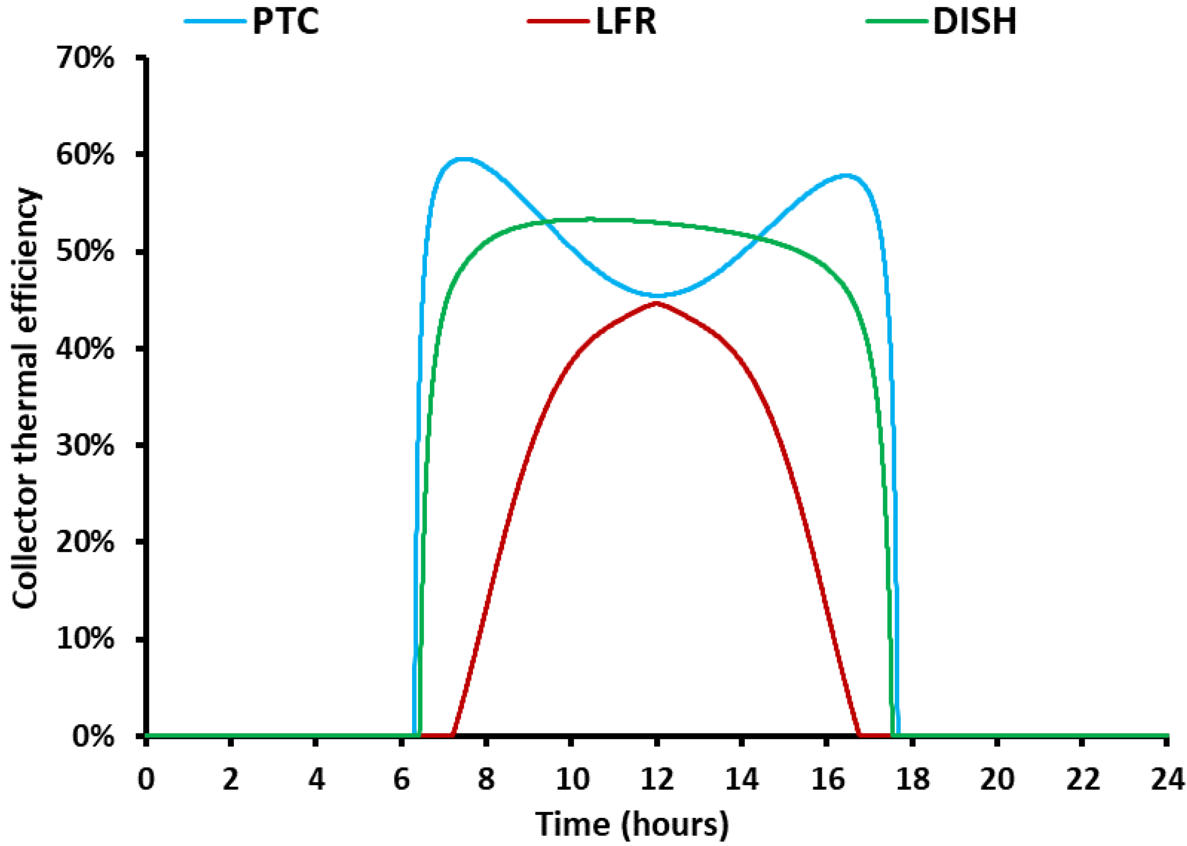
Figure 4 exhibits the daily variation of the collector thermal efficiency. The LFR had the lowest thermal efficiency among the examined technologies. The PTC presented the highest efficiency in the morning and in the afternoon, while the dish was the most efficient system close to solar noon. Practically, close to solar noon, the tracking system of the parabolic trough collector was not able to eliminate the optical loss due to the solar altitude, something that was possible with the solar dish. The results of the incident angle modifier of Figure 3 validate the previous statement.
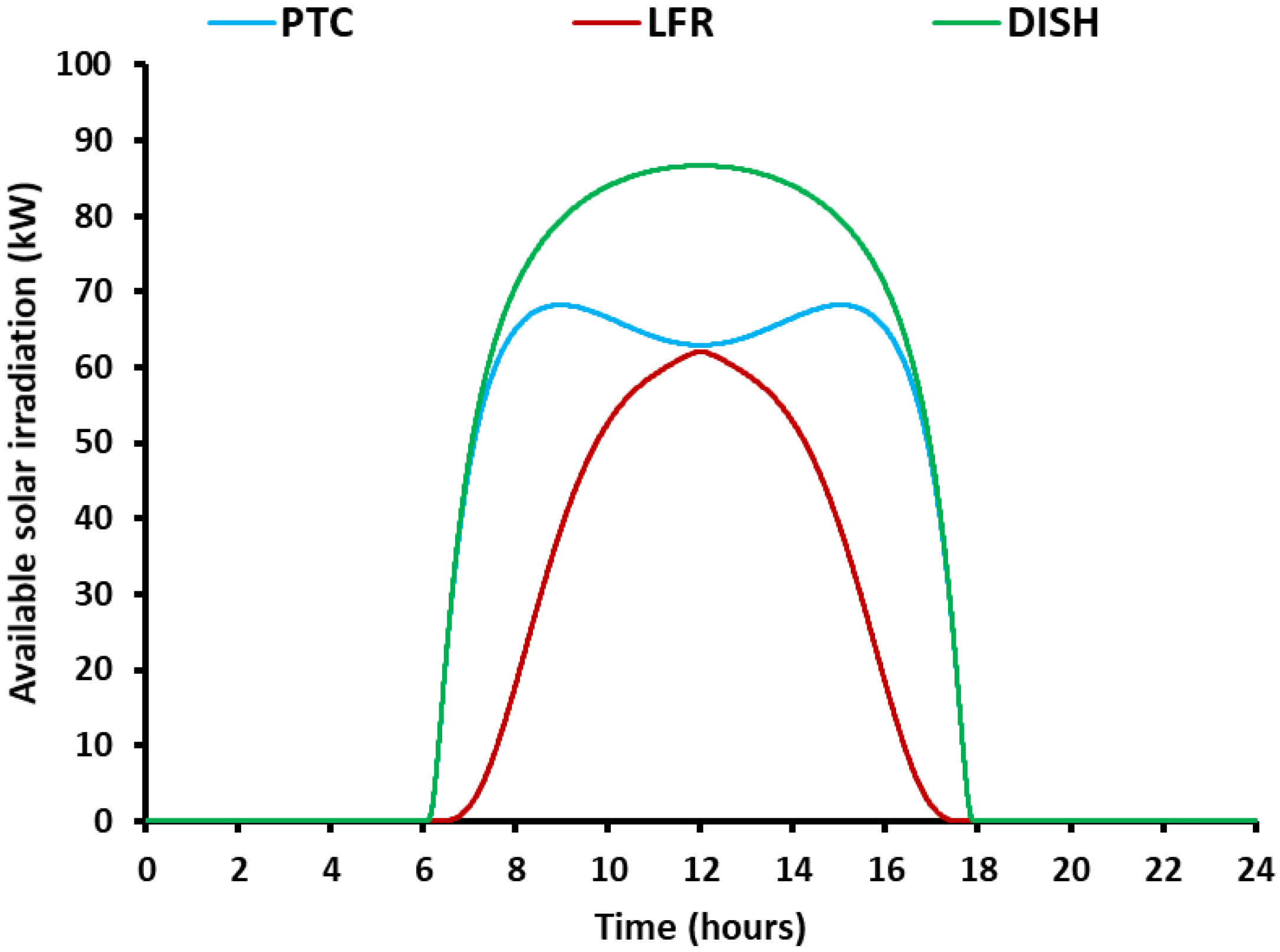
Figure 5 shows the daily variation of the available solar irradiation on the collector aperture. The quantity took into consideration the unavoidable optical losses due to the non-ideal tracking for the PTC and the LFR. For the dish, the available solar irradiation was practically equal to the solar irradiation due to the two-axis tracking system. So, the highest available solar irradiation was found for the dish with the PTC and the LFR to follow, respectively. At solar noon, the PTC and LFR had the same available solar irradiation because the transversal incident solar angle was zero and so there were the same optical losses in both systems due to the solar position.
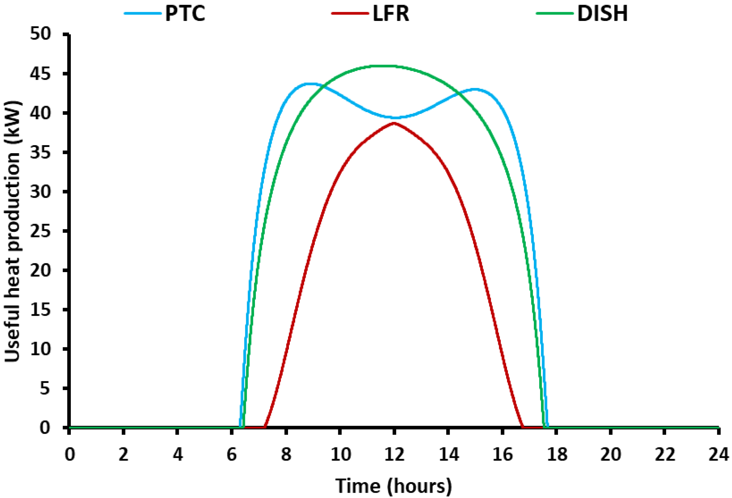
Figure 6 illustrates the daily variation of the useful heat production. It was found that the LFR had the lowest heat production throughout the day, while the dish was the best case close to the solar noon. The PTC was the most efficient choice during the morning and afternoon hours. It is important to state that this figure gives similar results to Figure 4 because the useful heat production is dependent on the collector thermal efficiency.
At this point, it must be stated that the PTC presented higher efficiency than the dish in the morning because it had a higher thermal performance (see Figure 4), while these collectors had similar IAM in the morning, close to 1 (see Figure 3). However, after 9:00, the dish presented higher efficiency than the PTC because the IAM of the PTC reduced close to the solar noon. The reduction in the PTC’s IAM was justified by the use of a single-axis tracking system that could not eliminate the end losses close to the solar noon, while the dish had a two-axis tracking mechanism that made the solar rays vertical on its aperture throughout the day.
In addition, it is valuable to state that the performance during the afternoon was lower compared to the morning efficiency because there were higher operating temperatures inside the tank in the afternoon and so the thermal efficiency was reduced. Figure 7 can validate this result. More specifically, Figure 7 shows that the tank temperature increased from the morning up to the afternoon for the PTC and dish, while it presents a smaller variation for the LFR. Practically, the LFR led to relatively low useful heat production and so small amounts of heat were stored, which made the daily variation of the mean storage temperature relatively low. The high PTC thermal efficiency in the morning made the tank temperature the highest for the PTC case in the morning but at noon and in the afternoon, the dish had a higher storage tank temperature.

3.2. Monthly and Yearly Performance of the Studied Cases

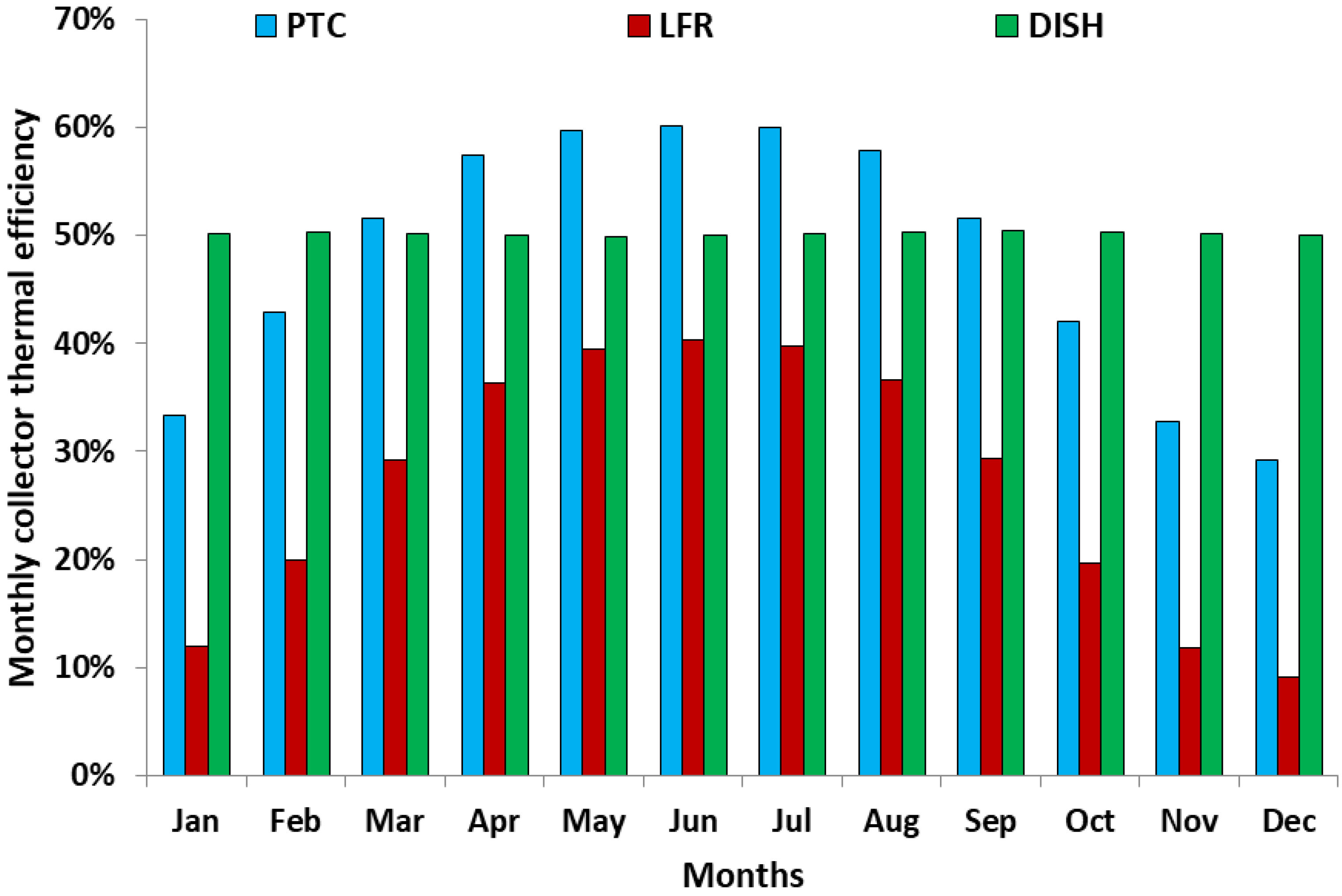
The next step in this work is the presentation of the results on a monthly basis. Figure 8 shows the collector’s thermal efficiency for all the months. The LFR had an extremely low performance during the winter period due to the relatively low solar altitude. More specifically, in December the LFR had 9.14% thermal efficiency and in June, 49.96%. The solar dish had an approximately constant performance throughout the year which was close to 50%. The PTC presented 29.19% thermal efficiency in December and 60.11% in June. It is remarkable to state that the PTC was better than the dish for seven months from March up to September.
At this point, it must be stated that the optical efficiency variation due to the different sun angles during the year had the highest influence on collector efficiency. The solar dish operated with a two-axis tracking system and thus it had maximum optical efficiency throughout the year. On the other hand, the PTC and LFR had single-axis tracking systems because they were linear concentrating systems and thus they had optical losses due to the different sun altitudes. Moreover, the LFR had higher optical losses due to the tracking restrictions of the mirrors which were close to the ground. So, the variation of the collector efficiency was higher in the LFR throughout the year, it was lower in the PTC and it was extremely low in the dish. Furthermore, it must be stated that the ambient temperature and the solar irradiation level were variable during the year but their impact on the collector efficiency was low due to the low values of the thermal losses in concentrating systems. On the other hand, the solar irradiation potential had a high influence on the useful heat production because the solar irradiation potential was multiplied with the mean monthly efficiency value in order to give the monthly yield in useful heat production.
The system’s electricity production is given in Figure 9 for all the collector types. This figure has a different shape than Figure 8 because the solar energy amount of every month was taken into consideration in every case. The winter period is a period with a low number of sunny days and so the electricity production is too low due to the low available solar energy and the low thermal efficiency. The maximum electricity production was found in July at 3238 kWh with the PTC, while 2677 kWh with the DISH (solar dish) and 2078 kWh with LFR. On the other hand, the electricity production in December was 491 kWh, 929 kWh and 69 kWh with the PTC, DISH and LFR, respectively.
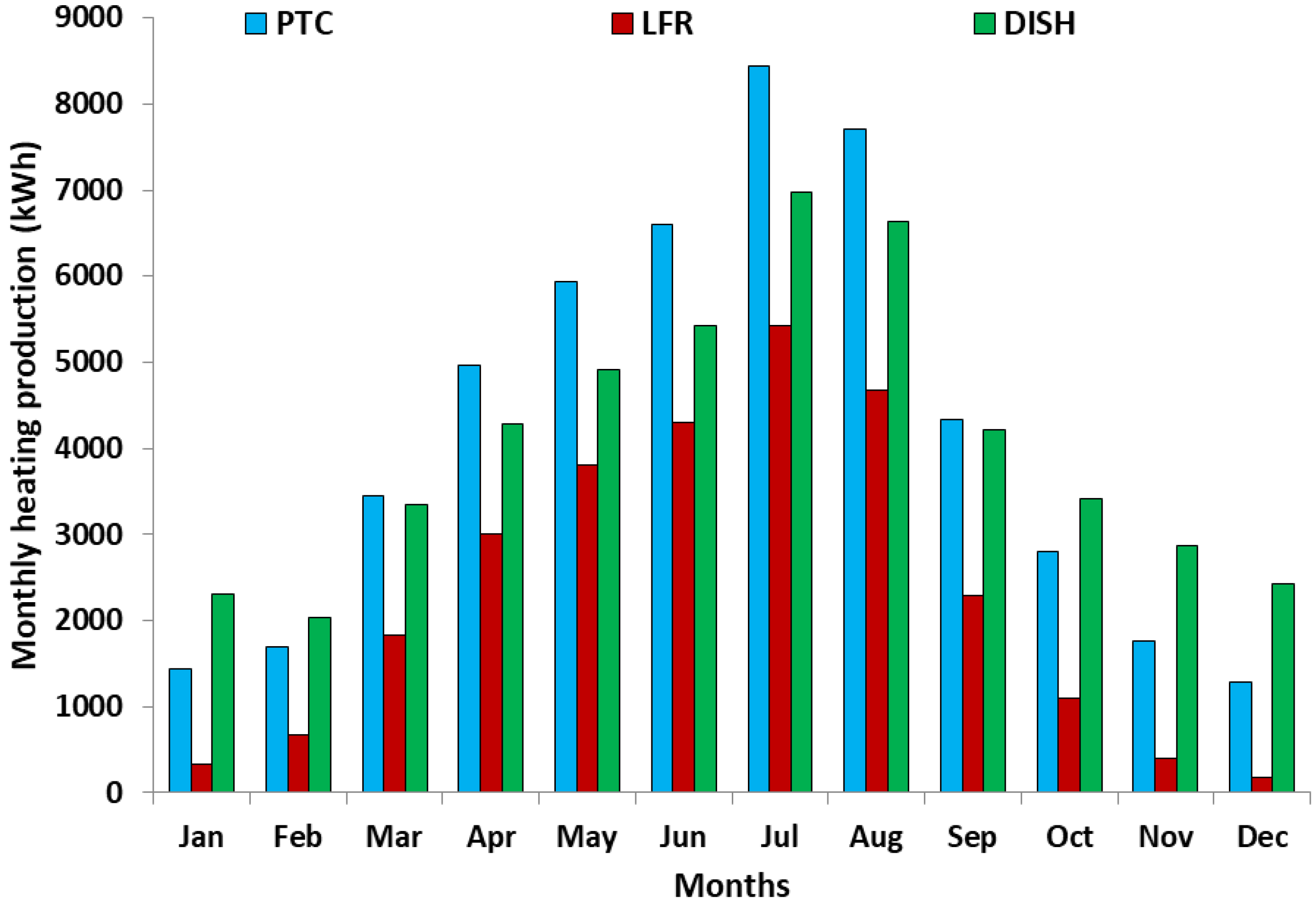
Figure 10 depicts the heating production of the examined cases for all the months. The results of Figure 10 are proportional to the electricity results that are given in Figure 9. The maximum heating production was found in July at 8447 kWh with the PTC, while 6982 kWh with the DISH and 5419 kWh with the LFR. On the other hand, the heating production in December was 1282 kWh, 2422 kWh and 180 kWh with the PTC, DISH and LFR, respectively.
Figure 11 illustrates the cooling production of the examined cases for all the months. The results of Figure 11 are proportional to the results of Figure 9 and Figure 10 of the electricity and the heating production, respectively. The maximum cooling production was found in July at 7814 kWh with the PTC, while 6459 kWh with the DISH and 5013 kWh with the LFR. On the other hand, the cooling production in December was 1186 kWh, 2241 kWh and 166 kWh with the PTC, DISH and LFR, respectively.
Figure 12 exhibits the system energy efficiency during the months. This parameter follows similar trends with the collector thermal efficiency, as in Figure 8. The maximum energy efficiency was found in June at 76.61% with the PTC, while 49.88% with the LFR and 62.96% with the DISH. In December, the system energy efficiency was 31.86%, 4.47% and 60.20% with the PTC, LFR and DISH, respectively. The system performance with the LFR was extremely low during the winter, something that makes its application face important limitations in Greece during the winter period.
At the end of the results section, Table 4 summarizes the yearly results of the system performance. The yearly energy performance was found to be 64.40%, 35.78% and 62.41% with the PTC, LFR and DISH, respectively. The yearly exergy performance was found to be 16.63%, 9.24% and 16.12% with the PTC, LFR and DISH, respectively. The investment simple payback period was found to be 6.25, 10.92 and 6.95 years with the PTC, LFR and DISH, respectively.
The results indicate that the most effective technologies for the trigeneration system are the PTC and the solar dish. The LFR was found to be the least efficient system and the system which led to the maximum payback period, thus it is better not to be selected for driving trigeneration configurations. The PTC was the best system, and the dish led to slightly lower performance results. So, both these technologies could be selected for feeding trigeneration systems with heat. In the future, there is a need for performing similar comparative works for other locations with different weather data and especially different latitudes. An interesting question for future work is associated with the best solar technology at higher altitudes than Athens, which is 38°, in order to check if the PTC remains the best choice or not. The higher latitude may introduce higher optical losses in the PTC which is a linear concentrating technology, and this is the reason for investigating this issue further. Moreover, it must be stated that the solar-driven trigeneration systems are viable in locations with relatively high solar potentials in order to produce high amounts of useful output and to have a high yearly income.
Lastly, regarding the LFR, there is a need to develop an advanced design with lower optical losses in order to make it a more competitive technology energetically. More specifically, there are ideas with rotating platforms, extended receivers and inclined receivers which can lead to higher optical and consequently thermal performance. In any case, the respective increase in the cost has to be taken into consideration in every case.

4. Conclusions

The goal of this analysis is the investigation of three different solar concentrating technologies in a trigeneration system. Parabolic trough collectors, linear Fresnel reflectors and solar dishes are compared in energetic, exergetic and financial terms. The trigeneration unit consists of an ORC and an H2O/LiBr absorption chiller for producing cooling and heating. The present investigation is conducted for the weather data of Athens in Greece. The main conclusions of the present paper are included in the next bullets:
  • The PTC is found to be the best technology from an energy and financial point of view. The solar dish is second, with a small difference to the PTC, while the LFR is the least efficient technology.
  • The solar dish is able to provide a more uniform production profile throughout the year compared to the other systems.
  • The performance of the LFR is extremely low during the winter and it is not recommended to be used in winter applications in Greece.
  • The yearly energy performance is found to be 64.40%, 35.78% and 62.41% with the PTC, LFR and dish, respectively.
  • The yearly exergy performance is found to be 16.63%, 9.24% and 16.12% with the PTC, LFR and dish, respectively.
  • The investment simple payback period is found to be 6.25, 10.92 and 6.95 years with the PTC, LFR and dish, respectively. These results indicate that all cases lead to viable systems.

Author Contributions

Conceptualization, E.B.; methodology, E.B.; software, E.B.; formal analysis, E.B.; investigation, E.B.; writing—original draft preparation, E.B. and C.T.; writing—review and editing, E.B. and C.T.; supervision, C.T. All authors have read and agreed to the published version of the manuscript.

Funding

This research is co-financed by Greece and the European Union (European Social Fund—ESF) through the Operational Programme «Human Resources Development, Education and Lifelong Learning» in the context of the project “Reinforcement of Postdoctoral Researchers—2nd Cycle” (MIS-5033021), implemented by the State Scholarships Foundation (ΙΚΥ).
Applsci 10 04492 i001

Acknowledgments

Evangelos Bellos would like to thanks the State Scholarships Foundation (ΙΚΥ) for its financial support (MIS-5033021).

Conflicts of Interest

The authors declare no conflict of interest.

Nomenclature

AcolSolar field area, m2
C0Investment cost, €
CFCash flow on a yearly basis, €
EEnergy amount, kWh
GbSolar direct beam irradiation, W m−2
hSpecific enthalpy, kJ kg−1
KCollector incident angle modifier, -
mrRefrigerant mass flow rate, kg s−1
PelElectricity power, kW
QHeat/energy rate, kW
SPPInvestments simple payback period, years
TTemperature level, °C
WpPumping work, kW
WTTurbine work, kW

Greek Symbols

ηEfficiency, -
θIncident angle of the sun, o
θLProjection of the sun angle along the longitudinal direction, °
θtProjection of the sun angle along the transversal direction, °

Subscripts and Superscripts

amambient
availavailable
con,incondenser inlet
con,outcondenser outlet
colcollector
coolcooling
DISHSolar dish
elelectricity
enenergy
evap,inevaporator inlet
evap,outevaporator outlet
exexergy
ffluid
heatheating
LFR Linear Fresnel reflector
lossstorage tank losses
mgelectromechanical
PTC Parabolic trough collector
solsolar
ststorage
sunsun
ththermal
uuseful

Abbreviations

EES Engineering Equation Solver
HRS Heat Recovery System
IAM Incident angle modifier
LFR Linear Fresnel Reflector
ORC Organic Rankine Cycle
PTC Parabolic Trough Collector
SD Solar Dish

References

  1. Ayou, D.S.; Coronas, A. New Developments and Progress in Absorption Chillers for Solar Cooling Applications. Appl. Sci. 2020, 10, 4073. [Google Scholar] [CrossRef]
  2. Sun, L.; Wang, Y.; Wang, D.; Xie, Y. Parametrized Analysis and Multi-Objective Optimization of Supercritical CO2 (S-CO2) Power Cycles Coupled with Parabolic Trough Collectors. Appl. Sci. 2020, 10, 3123. [Google Scholar] [CrossRef]
  3. Fuqiang, W.; Ziming, C.; Jianyu, T.; Yuan, Y.; Yong, S.; Linhua, L. Progress in concentrated solar power technology with parabolic trough collector system: A comprehensive review. Renew. Sustain. Energy Rev. 2017, 79, 1314–1328. [Google Scholar] [CrossRef]
  4. Bellos, E.; Tzivanidis, C. Alternative designs of parabolic trough solar collectors. Prog. Energy Combust. Sci. 2019, 71, 81–117. [Google Scholar] [CrossRef]
  5. Nathan, G.J.; Jafarian, M.; Dally, B.B.; Saw, W.L.; Ashman, P.J.; Hu, E.; Steinfeld, A. Solar thermal hybrids for combustion power plant: A growing opportunity. Prog. Energy Combust. Sci. 2018, 64, 4–28. [Google Scholar] [CrossRef]
  6. Kasaeian, A.; Nouri, G.; Ranjbaran, P.; Wen, D. Solar collectors and photovoltaics as combined heat and power systems: A critical review. Energy Convers. Manag. 2018, 156, 688–705. [Google Scholar] [CrossRef] [Green Version]
  7. Wu, D.W.; Wang, R.Z. Combined cooling, heating and power: A review. Prog. Energy Combust. Sci. 2006, 32, 459–495. [Google Scholar] [CrossRef]
  8. Daneshazarian, R.; Cuce, E.; Cuce, P.M.; Sher, F. Concentrating photovoltaic thermal (CPVT) collectors and systems: Theory, performance assessment and applications. Renew. Sustain. Energy Rev. 2018, 81, 473–492. [Google Scholar] [CrossRef]
  9. Sher, F.; Kawai, A.; Güleç, F.; Sadiq, H. Sustainable energy saving alternatives in small buildings. Sustain. Energy Technol. Assess. 2019, 32, 92–99. [Google Scholar] [CrossRef]
  10. Cuce, E.; Sher, F.; Sadiq, H.; Cuce, P.M.; Guclu, T.; Besir, A.B. Sustainable ventilation strategies in buildings: CFD research. Sustain. Energy Technol. Assess. 2019, 36, 100540. [Google Scholar] [CrossRef]
  11. Cuce, E.; Nachan, Z.; Cuce, P.M.; Sher, F.; Neighbour, G.B. Strategies for ideal indoor environments towards low/zero carbon buildings through a biomimetic approach. Int. J. Ambient Energy 2019, 40, 86–95. [Google Scholar] [CrossRef]
  12. Al-Sulaiman, F.A.; Dincer, I.; Hamdullahpur, F. Exergy modeling of a new solar driven trigeneration system. Sol. Energy 2011, 85, 2228–2243. [Google Scholar] [CrossRef]
  13. Bellos, E.; Tzivanidis, C. Parametric analysis and optimization of a solar driven trigeneration system based on ORC and absorption heat pump. J. Clean. Prod. 2017, 161, 493–509. [Google Scholar] [CrossRef]
  14. Eisavi, B.; Khalilarya, S.; Chitsaz, A.; Rosen, M.A. Thermodynamic analysis of a novel combined cooling, heating and power system driven by solar energy. Appl. Therm. Eng. 2018, 129, 1219–1229. [Google Scholar] [CrossRef]
  15. Zhao, L.; Zhang, Y.; Deng, S.; Ni, J.; Xu, W.; Ma, M.; Lin, S.; Yu, Z. Solar driven ORC-based CCHP: Comparative performance analysis between sequential and parallel system configurations. Appl. Therm. Eng. 2018, 131, 697–706. [Google Scholar] [CrossRef]
  16. Khalid, F.; Dincer, I.; Rosen, M.A. Techno-economic assessment of a renewable energy based integrated multigeneration system for green buildings. Appl. Therm. Eng. 2016, 99, 1286–1294. [Google Scholar] [CrossRef]
  17. Bellos, E.; Vellios, L.; Theodosiou, I.-C.; Tzivanidis, C. Investigation of a solar-biomass polygeneration system. Energy Convers. Manag. 2018, 173, 283–295. [Google Scholar] [CrossRef]
  18. Tzivanidis, C.; Bellos, E. A Comparative Study of Solar-Driven Trigeneration Systems for the Building Sector. Energies 2020, 13, 2074. [Google Scholar] [CrossRef] [Green Version]
  19. Dabwan, Y.N.; Gang, P.; Li, J.; Gao, G.; Feng, J. Development and assessment of integrating parabolic trough collectors with gas turbine trigeneration system for producing electricity, chilled water, and freshwater. Energy 2018, 162, 364–379. [Google Scholar] [CrossRef]
  20. Moaleman, A.; Kasaeian, A.; Aramesh, M.; Mahian, O.; Sahota, L.; Tiwari, G.N. Simulation of the performance of a solar concentrating photovoltaic-thermal collector, applied in a combined cooling heating and power generation system. Energy Convers. Manag. 2018, 160, 191–208. [Google Scholar] [CrossRef]
  21. Thomas, S.; Kumar, A.; Sahoo, S.; Varghese, S. Energy and Exergy Analysis of Solar Thermal Energy-based Polygeneration Processes for Applications in Rural India. Int. Energy J. 2018, 18, 243–256. [Google Scholar]
  22. Dabwan, Y.N.; Pei, G.; Gao, G.; Feng, J.; Li, J. A novel integrated solar tri-generation system for cooling, freshwater and electricity production purpose: Energy, economic and environmental performance analysis. Sol. Energy 2020, 198, 139–150. [Google Scholar] [CrossRef]
  23. Hogerwaard, J.; Dincer, I.; Naterer, G.F. Solar energy based integrated system for power generation, refrigeration and desalination. Appl. Therm. Eng. 2017, 121, 1059–1069. [Google Scholar] [CrossRef]
  24. El-Emam, R.S.; Dincer, I. Assessment and Evolutionary Based Multi-Objective Optimization of a Novel Renewable-Based Polygeneration Energy System. J. Energy Resour. Technol. 2016, 139, 012003. [Google Scholar] [CrossRef]
  25. Ullvius, N.C.; Rokni, M. A study on a polygeneration plant based on solar power and solid oxide cells. Int. J. Hydrog. Energy 2019, 44, 19206–19223. [Google Scholar] [CrossRef]
  26. Mohammadi, K.; McGowan, J.G. Thermodynamic analysis of hybrid cycles based on a regenerative steam Rankine cycle for cogeneration and trigeneration. Energy Convers. Manag. 2018, 158, 460–475. [Google Scholar] [CrossRef]
  27. Khalid, F.; Dincer, I.; Rosen, M.A. Energy and exergy analyses of a solar-biomass integrated cycle for multigeneration. Sol. Energy 2015, 112, 290–299. [Google Scholar] [CrossRef]
  28. F-Chart Software. Engineering Equation Solver (EES). 2015. Available online: http://www.fchart.com/ees (accessed on 5 March 2020).
  29. Bellos, E.; Tzivanidis, C.; Antonopoulos, K.A. Exergetic, energetic and financial evaluation of a solar driven absorption cooling system with various collector types. Appl. Therm. Eng. 2016, 102, 749–759. [Google Scholar] [CrossRef]
  30. Therminol VP1. Available online: https://www.therminol.com/products/Therminol-VP1 (accessed on 5 March 2020).
  31. Duffie, J.A.; Beckman, W.A. Solar Engineering of Thermal Processes, 2nd ed.; John Wiley & Sons Inc.: New York, NY, USA, 1991. [Google Scholar]
  32. Bellos, E.; Tzivanidis, C. Performance analysis and optimization of an absorption chiller driven by nanofluid based solar flat plate collector. J. Clean. Prod. 2018, 174, 256–272. [Google Scholar] [CrossRef]
  33. Petela, R. Exergy of undiluted thermal radiation. Sol. Energy 2003, 74, 469–488. [Google Scholar] [CrossRef]
  34. EuroTrough II: Extension, Test and Qualification of EUROTROUGH from 4 to 6 Segments at Plataforma Solar de Almeria; Project Cooordinator: Instalaciones Inabensa, S.A, Sevilla, Spain, 2003.
  35. Bellos, E.; Tzivanidis, C. Assessment of linear solar concentrating technologies for Greek climate. Energy Convers. Manag. 2018, 171, 1502–1513. [Google Scholar] [CrossRef]
  36. Bellos, E.; Pavlovic, S.; Stefanovic, V.; Tzivanidis, C.; Nakomcic-Smaradgakis, B.B. Parametric analysis and yearly performance of a trigeneration system driven by solar-dish collectors. Int. J. Energy Res. 2019, 43, 1534–1536. [Google Scholar] [CrossRef]
  37. Montes, M.J.; Abánades, A.; Martínez-Val, J.M.; Valdés, M. Solar multiple optimization for a solar-only thermal power plant, using oil as heat transfer fluid in the parabolic trough collectors. Sol. Energy 2009, 83, 2165–2176. [Google Scholar] [CrossRef] [Green Version]
  38. Bellos, E.; Tzivanidis, C. Parametric Investigation of a Trigeneration System with an Organic Rankine Cycle and Absorption Heat Pump Driven by Parabolic Trough Collectors for the Building Sector. Energies 2020, 13, 1800. [Google Scholar] [CrossRef] [Green Version]
  39. Kouremenos, D.A.; Antonopoulos, K.A.; Domazakis, E.S. Solar radiation correlations for the Athens, Greece, area. Sol. Energy 1985, 35, 259–269. [Google Scholar] [CrossRef]
  40. Bellos, E.; Tzivanidis, C.; Belessiotis, V. Daily performance of parabolic trough solar collectors. Sol. Energy 2017, 158, 663–678. [Google Scholar] [CrossRef]
  41. Bellos, E.; Tzivanidis, C.; Torosian, K. Energetic, exergetic and financial evaluation of a solar driven trigeneration system. Therm. Sci. Eng. Prog. 2018, 7, 99–106. [Google Scholar] [CrossRef]
Figure 1. The investigated solar-driven trigeneration unit of this work.
Applsci 10 04492 g001
Figure 2. The examined solar concentrating technologies.
Applsci 10 04492 g002
Figure 3. Daily variation of the incident angle modifier for the three collectors in June. PTC: parabolic trough collector; LFR: Linear Fresnel reflector; DISH: Solar dish.
Applsci 10 04492 g003
Figure 4. Daily variation of the collector thermal efficiency for the three collectors in June.
Applsci 10 04492 g004
Figure 5. Daily variation of the available solar irradiation for the three collectors in June.
Applsci 10 04492 g005
Figure 6. Daily variation of the useful heat production for the three collectors in June.
Applsci 10 04492 g006
Figure 7. Daily variation of the storage tank mean temperature for the three collectors in June.
Applsci 10 04492 g007
Figure 8. Monthly collector thermal efficiency for the three solar collectors.
Applsci 10 04492 g008
Figure 9. Monthly electricity production for the three solar collectors.
Applsci 10 04492 g009
Figure 10. Monthly heating production for the three solar collectors.
Applsci 10 04492 g010
Figure 11. Monthly cooling production for the three solar collectors.
Applsci 10 04492 g011
Figure 12. Monthly system energy efficiency for the three solar collectors.
Applsci 10 04492 g012
Table 1. Main data of the studied system.
ParametersValues
Solar field and storage tank
Solar field area100 m2
Collector mass flow rate2 kg s−1
Maximum operating temperature400 °C
Storage volume of the tank4 m3
Tank thermal loss coefficient 0.5 W m−2 K−1
Organic Rankine Cycle
Superheating in the turbine20 °C
Recuperator pinch point10 °C
HRS pinch point5 °C
Turbine isentropic efficiency85%
Electromechanical efficiency97%
Absorption machine
Cooling production temperature5 °C
Heating production temperature60 °C
Effectiveness of the solution heat exchanger 70%
Generator temperature115 °C
Absorber temperature40 °C
Table 2. Data of the system in the nominal design point.
ParametersValues
Nominal solar direct beam irradiation700 W m−2
Nominal incident sun angle30°
Nominal level of the ambient temperature 25 °C
Operating time during the year2500 h
Nominal electricity power7.72 kW
Nominal heating power20.14 kW
Nominal cooling power18.63 kW
Table 3. Economic input data of the present paper [36,41].
ParametersValues
Parabolic trough collector specific cost250 € m−2
Linear Fresnel reflector specific cost200 € m−2
Solar dish collector specific cost300 € m−2
Organic Rankine cycle specific cost3000 € kWel−1
Storage tank specific cost1000 € m−3
Absorption chiller specific cost1000 € kWcool−1
Cooling production cost0.067 € kWh−1
Electricity production cost0.2 € kWh−1
Heating production cost0.1 € kWh−1
Cost for operation and maintenance 1% of the C0
Table 4. The final comparative results of the present work.
ParametersPTCLFRDISH
Electricity production—Eel (kWh)19,32810,73718,730
Heating production—Eheat (kWh)50,41728,00848,858
Cooling production—Ecool (kWh)46,63625,90845,195
Collector heat production—Eu (kWh)93,36155,33190,622
Solar energy—Esol (kWh)180,705180,705180,705
Energy efficiency—ηen (-)64.40%35.78%62.41%
Exergy efficiency—ηex (-)16.63%9.24%16.12%
Simple payback period—SPP (years)6.2510.926.95