Abstract
Fabric core conveyor belt rubber bearing (CBRB) with low cost and a simple manufacturing process has been proposed to further popularize seismic isolation technology in low-rise buildings, and four samples of such bearings have been produced, including four-layer, five-layer, five-layer with inner pattern and six-layer fabric core CBRBs. The vertical compression and the compression shear test are carried out to evaluate the performances of the four bearings. Results show that the vertical stiffness of the CBRB increases as the number of fabric core layer increases, while the damping ratio decreases, and the bearings can withstand a vertical pressure of 10 MPa. In addition, these bearings work very well within 100% shear strain, and the horizontal stiffness of the bearings decreases with increasing shear strain. In the meantime, as the number of fabric core layer increases, the effective horizontal stiffness of the bearings increases under 4 MPa compressive stress, and the damping ratio coefficient of the bearing is about 15%, when bearing sliding does not occur. The ultimate shear strain reached up to 200% for the four-layer bearing with obvious interlayer cracks, which means that the bonding quality between layers is the key influencing factor on the ultimate shear strain. In short, the proposed low-cost bearing has low horizontal stiffness and good energy dissipation capacity, so it is suitable for low-rise buildings in economically underdeveloped, high intensity areas, which can significantly improve their earthquake resistance and reduce casualties and property losses.
1. Introduction
China is a country prone to earthquakes with a seismic of being 6 degrees and above, accounting for about 80% of the country’s total land area. During recent strong earthquakes, including the Wenchuan, Yushu and Lushan earthquakes, a large number of low-rise houses have collapsed and been destroyed (Figure 1). Unlike the commodity apartment, the majority of low-rise houses in China are built by local people lacking professional training; such houses are simple in structure and low in cost, but it is often seriously inadequate for earthquake resistance. Therefore, it is necessary to adopt efficient and low-cost measures to improve the anti-seismic capacities of low-rise buildings in high intensity areas.

Figure 1.
Damages of low-rise buildings during Yushu earthquake in China.
Since the 1960s, seismic isolation technology was introduced to structures, and has become the most mature technical measure in the field of vibration control. Its basic principle is to magnify the natural vibration period and increase the damping of structures, by setting a seismic isolation layer with relatively low stiffness and high damping between the foundation and the superstructure, thereby effectively reducing the structural seismic response [1]. For the devices used in the seismic isolation layer, the laminated rubber bearing is very suitable for urban high-rise buildings, hospitals and other public projects [2], due to its mature manufacturing technology and stable working performance. However, these bearings are expensive and rarely used in low-rise buildings. Therefore, it is meaningful to find a more economic isolation device to improve the seismic performance of low-rise houses.
In 1999, Kelly [3] suggested that the steel reinforcing plates in the laminated steel rubber bearing can be replaced with fiber reinforcement, and conducted theoretical derivation and experimental research on this fiber reinforced rubber bearing. Moon et al. [4] and Strauss et al. [5] compared the mechanical properties of steel-reinforced laminated rubber bearings and fiber-reinforced ones by experiment. Kang et al. [6] further studied the effect of adding lead plug in fiber reinforced elastomeric bearings. Toopchi-Nezhad et al. [7,8,9,10] studied the shear deformation features and mechanical properties of unbonded fiber-reinforced rubber bearings. By using the finite element method, Toopchi-Nezhad et al. [11] and Al-Anany et al. [12] compared the mechanical properties of unbonded and bonded fiber reinforced rubber bearings. Van Engelen et al. [13,14] has proposed partially bonded fiber-reinforced elastomeric isolators, in order to eliminate the defect whereby the unbonded bearings are not capable of resisting tensile forces and potentially slip. Mordini et al. [15], Das et al. [16], Thuyet et al. [17] and Al-anany et al. [18] studied the seismic isolation efficiency of applying the bearings to buildings and bridges. In addition to the above researches, in order to reduce the manufacturing cost and production difficulty of the bearing, some scholars studied the influence of changing the manufacturing method, the material and form of the fiber and the rubber material on the bearing. For example, Ashkezari et al. [19] studied the steel like fiber reinforced elastomeric seismic isolators through experiments; Dezfuli et al. [20,21] made carbon fiber reinforced rubber bearings by the cold vulcanization method; Naghshineh et al. [22,23] studied the mechanical properties of new types of fiber-mesh-reinforced seismic isolators; Spizzuoco et al. [24] introduced the recycled tire rubber as the reinforced fiber to replace steel; Ping et al. [25] and Hua et al. [26] used unsaturated polyester glass fiber reinforced plastic plates as the reinforcement layer. In addition to the above fiber-reinforced rubber bearings, Menga et al. [27] studied the performance of a rubber-layer roller bearing (RLRB), and determined the optimal sizes and dimensions to the component parts of the bearing. In general, the above rubber bearings suitable for low-rise buildings are developing towards a more economical and environmentally friendly future.
The conveyor belt is a common industrial belt used to carry and transport materials, composed generally of four parts: skeleton (fabric core), core rubber, upper and lower cover [28] (Figure 2a). The core of the fabric conveyor belt is mainly formed by alternate fiber layers and core rubber layers. There are usually four to six fabric fiber layers in the conveyor belt, and its material is generally nylon, polyester, aramid, etc. Unlike the previous fiber-reinforced rubber bearing [3,4,5,6,7,8,9,10,11,12,13,14,15,16,17,18,19,20,21,22,23,24,25,26], which is made of a fiber layer and a rubber layer laminated at a fixed interval (Figure 2b), the fabric core conveyor belt rubber bearing (CBRB) proposed in this paper (Figure 2c) is formed by directly stacking and bonding the fabric core conveyor belt with appropriate adhesive.
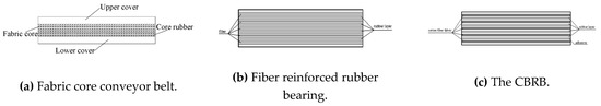
Figure 2.
Schematic diagram of different structures. (a) Fabric core conveyor belt; (b) Fiber reinforced rubber bearing; (c) The conveyor belt rubber bearing (CBRB).
In addition, the manufacturing method of the new type of bearing used a relatively simple and economical cold bonding technology. Applying this type of bearing to the isolation of low-rise houses can reduce the seismic response of structures and control the cost well. This paper conducted vertical compression and horizontal compression-shear tests on the CBRBs. The results obtained can provide a theoretical reference for its application in low-rise buildings.
2. Fabric Core Conveyor Belt Rubber Bearings
The plane size of the CBRB is 150 mm × 150 mm. According to the layers of the fabric core and the rubber shape in the conveyor belt, 4 layer, 5 layer, 6 layer and 5 layer with pattern CBRBs were manufactured, respectively represented by the numbers R1, R2, R4 and R3. According to the semi-empirical Equation (1) [29], the elastic modulus of the rubber whose Shore hardness (HA) is 70 degrees is 5.54 MPa. The shear modulus G is 1.85 MPa from Equation (2), where Poisson’s ratio μ1 is equal to 0.5. The thickness of the single-layer fiber fabric is assumed to be 0.25 mm. The specific parameters of each bearing are shown in Table 1. The shape factor S of a square shaped isolator is the ratio between the loaded area and the lateral surface free to bulge [30]. The shape factor S was calculated by the following Equation (3) [30]. In formula (3), A represents the area of the rectangular bearing; a represents the side length of the square bearing; tr represents the thickness of the single-layer rubber layer.

Table 1.
Parameters table of fabric core conveyor belt rubber bearing. R1 = 4 layers; R2 = 5 layers; R3 = 5 layer with pattern CBRBs; R4 = 6 layers.
2.1. Manufacturing Method of Bearings
The manufacturing process of CBRBs is as follows: (1) the conveyor belt is cut into square pieces of the same size by a cutting machine; (2) the surface of the cut conveyor belt pieces is coated with conveyor belt adhesive, and stack the pieces vertically; (3) place the stacked conveyor belt pieces on the press machine, apply 1 MPa surface pressure and keep it at room temperature for 8 h, the bearing can be finally formed [20]. Four samples of the bearing produced are shown in Figure 3.

Figure 3.
The sample of bearings. (a) Partially enlarged view of R1; (b) partially enlarged view of R2; (c) partially enlarged view of R4; (d) partially enlarged view of R3; (e) the side view of four bearings.
2.2. Uniaxial Tensile Test of Fabric Core Conveyor Belt
In order to understand the mechanical properties of the rubber and the effect of the increased fabric core layers in the rubber, the uniaxial tensile test was conducted on pure rubber specimen and five-layer fabric core conveyor belt, and some mechanical parameters, such as the tensile strength and elongation at break, were measured. The thickness of dumbbell-shaped specimen of the five-layer fabric core is 9 mm, and the thickness of the pure rubber is 3.8 mm. The planar dimensions of the dumbbell-shaped specimens are shown in Figure 4a. All the six test pieces were finally broken, as shown in Figure 4b. The maximum tensile force, tensile strength and elongation at break of the specimens are listed in Table 2. It can be seen from Table 2 that the mechanical properties of different specimens are less discrete. After the fabric core is added, the tensile strength of the material is greatly improved, and the elongation at break is controlled by the fabric layer, which is significantly reduced. It is worth noting that the elongation at break of the pure rubber cut from the fabric core conveyor belt in this study is significantly less than that of the rubber, in common laminated rubber bearings whose elongation at break are generally greater than 400%. This defect will be further considered in future research.
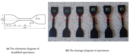
Figure 4.
The dumbbell specimens. (a) The schematic diagram of dumbbell specimens; (b) the damage diagram of specimens.
Table 2.
Parameter summary list for uniaxial tensile test of the dumbbell specimen.
3. Vertical Mechanical Properties Test of Rubber Bearing of Fabric Core Conveyor Belt
3.1. Vertical Tests Program
In this paper, vertical compressive cycle test and ultimate compressive test were carried out on the four bearings. As shown in Figure 5, specimens are slowly loaded up to 4 MPa vertical pressure, and then three fully reversed cycles with amplitude ±1.2 MPa (±30%) are exerted. The vertical stiffness of the bearings is calculated from the third hysteresis curve. The ultimate compressive test is carried out according to the load mode of 0–10 MPa (Figure 6), and finally the bearing is observed to establish whether there is any damage or other unusual phenomena.

Figure 5.
Variation of vertical pressure over time for design pressures.

Figure 6.
Variation of vertical pressure over time for over pressures.
The vertical stiffness Kv of the bearing and the equivalent damping ratio ζv,eq are calculated according to the following two equations. In the two formulas, Y2 and Y1 are horizontal maximum positive and negative displacement; F2 and F1 are horizontal shear force corresponding to Y2 and Y1, and ΔW is the envelope area of the hysteresis curve.
3.2. Vertical Compressive Test
Under the vertical pressure, the two sides of the bearing bulge outwards. Due to the constraint of the fabric core in rubber, the bearing has a relatively high compression stiffness. During the whole compression tests of the four bearings, no visible tear was found in the adhesive layer of the bearing. The vertical compression force-displacement curves of the four bearings are shown in Figure 7, Figure 8, Figure 9 and Figure 10.
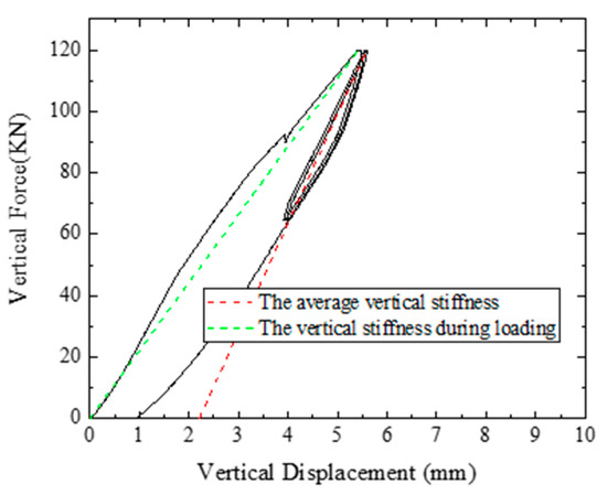
Figure 7.
The vertical compression force-displacement curve of R1.

Figure 8.
The vertical compression force-displacement curve of R2.

Figure 9.
The vertical compression force-displacement curve of R3.
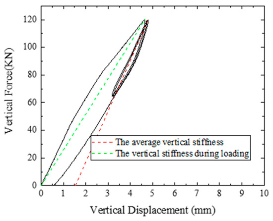
Figure 10.
The vertical compression force-displacement curve of R4.
As can be seen from Figure 7, Figure 8, Figure 9 and Figure 10, the bearings exhibit certain damping characteristics in the compression test, and the results show that the slope of the green secant in the loading stage is less than the slope of the red secant in the subsequent unloading stage, because of the so called run-in effect. The most likely reason of the effect is that the fiber fabrics are not straightened (as shown in Figure 11) during the manufacturing process of the conveyor belt, which means that the fiber fabrics cannot begin to limit the deformation of the rubber until they have been straightened by applying a certain vertical load [31]. In addition, in Figure 9, when the curve is at the beginning of the loading phase, the slope of the curve is significantly smaller than those of the other three bearings, which shows that there is a gap compaction process of the bearing, and also explains the residual displacement of R3 is larger than those of the other three bearings.
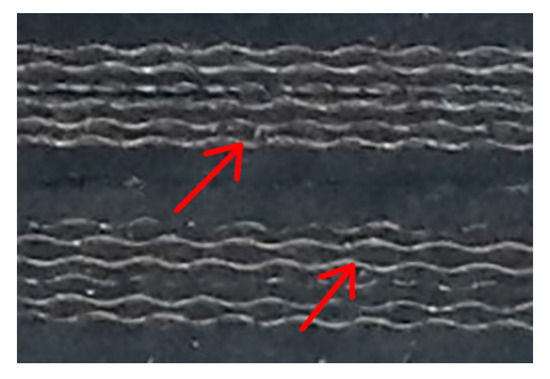
Figure 11.
Partially enlarged view of fabric core CBRB.
The effective vertical stiffness and damping of the four CBRBs are shown in Table 3. It can be seen that vertical stiffness of R3 is about 10% lower than that of R2, the vertical damping ratio is also slightly smaller than R2, due to the pattern rubber of R3. For the remaining three bearings, as the number of fabric core layer increases, the vertical stiffness also increases, and the effective damping ratio decreases continuously. Generally, the effective vertical damping ratio of the laminated steel plate rubber bearing is 2% to 4%, but the effective vertical damping ratio of the CBRBs is as high as 8%. The reasons may be as follows: (1) fabric core layers can produce a frictional damping, due to the interfacial slip between individual strands in the fiber core layers when the bearing is under vertical pressure; (2) according to formula (5), the lower vertical stiffness of the CBRBs compared with that of steel-reinforced laminated rubber bearings leads to the higher effective damping ratio.
Table 3.
Mechanical parameter of the fabric core CBRBs.
3.3. Overpressure Vertical Compressive Test
In this test, the vertical pressure of the four bearings is all loaded to 10 MPa, no visible interlayer splitting and pressure failure of the bearings was observed, and the corresponding overpressure force-displacement curves are shown in Figure 12.
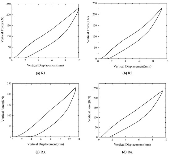
Figure 12.
Vertical compression curve of bearings: (a) R1; (b) R2; (c) R3; (d) R4.
It can be seen from Figure 12 that the rubber bearings of the fabric core conveyor belt work well under the pressure of 10 MPa, indicating that the vertical bearing capacity of this type of bearings is sufficient to meet the vertical bearing capacity requirements of low-rise buildings.
4. Horizontal Mechanical Properties Tests of CBRBs
4.1. Test Procedure and Setup for Horizontal Shear Test
As shown in Table 4, the horizontal performance test of the bearings includes horizontal cyclic compression-shear test and the ultimate compression-shear test. The horizontal cyclic tests were carried out on the four bearings mentioned above in sequence, and it was possible to observe whether the bearings have cracks or delamination during the test. Then, the ultimate horizontal shear test was carried out on the 4-layer CBRB, as an example to explore its ultimate shear strain. All the tests were conducted using displacement control with three fully reversed sinusoidal cycles for each shear strain, and the hysteresis curve of the third cycle is taken to calculate the mechanical parameters of bearings.
Table 4.
Test procedure for compression-shear test.
The effective horizontal stiffness of the bearing, Kh, and the equivalent damping ratio, ζeq, is calculated according to Equations (6) and (7), respectively.
where D2 and D1 are the peak lateral displacement, and Q2 and Q1 are the peak shear forces respectively. ΔW is the envelope area of the hysteresis curve.
The setup used in the horizontal shear test is shown in Figure 13. The main structure of the test setup is fixed on the base by four screws with a diameter of 30 mm. A vertical hydraulic jack is equipped to provide the vertical force with force control, and the load cells under the jack is used to measure the force. The horizontal loading system is performed as displacement control, and the displacement is applied by the hydraulic actuator. The bearing was located between the upper plate and the low plate. The upper plate is fixed by the left bracket, and the lower plate is attached to the horizontal actuator, which is fixed by the right bracket. Three steel rollers with a diameter of 20 mm are placed between the lower plate and the pad. During the test, it is necessary to ensure that the steel roller and the pad are smooth enough, and the dust on the pad should be cleaned in time.
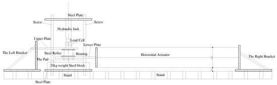
Figure 13.
General view of the compression- shear test equipment.
4.2. Horizontal Compression-Shear Cyclic Test
4.2.1. Description of the Test
During the compression-shear test, as the shear strain increases, the fabric core CBRB will exhibit the rollover deformation [7,8,9]. The rollover deformation means that the upper right (left) corner of the bearing curls downwards, and the lower left (right) corner curls upwards, as the shear displacement is towards right (left). This phenomenon will reduce the horizontal stiffness of the bearing and let the hysteresis curve exhibit bilinear characteristics, which enhances the energy dissipation capacity of the bearing. In this study, all bearings exhibited a rollover type of deformation.
In the test, the middle pointer can be neglected, since it has a slight tilt, due to the installation accuracy problem. As illustrated in Figure 14, taking the R2 bearing under 2 MPa compressive stress as representative, when the shear strain is 50%, the top and bottom rubber layers of R2 began to detach from the upper plate and the lower plate, which resulted in a slight curling; as the shear strain increased to 75%, the curling degree of the bearing increased and rollover deformation occurred; when the shear strain is 100%, the curl of the bearing continued to increase, and the side face of the bearing was totally inclined. At this time, no bonding problem was found in the bearing, which indicates that this new type of bearing works well under 100% shear deformation.

Figure 14.
Bearing R2 under compression-shear test with shear strains: (a) 0; (b) 50%; (c) 75%; (d) 100%.
4.2.2. Mechanical Properties Analyses
Figure 15, Figure 16, Figure 17 and Figure 18 show the hysteretic curves of the rubber bearings at different pressure levels (2 MPa, 4 MPa and 6 MPa) and shear strains (γ equal to 25%, 50%, 75% and 100%).

Figure 15.
Hysteretic curves of R1: (a) 2 MPa; (b) 4 MPa; (c) 6 MPa.
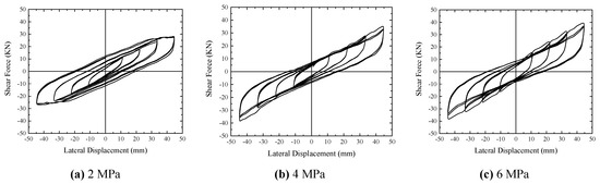
Figure 16.
Hysteretic curves of R2: (a) 2 MPa; (b) 4 MPa; (c) 6 MPa.
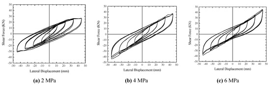
Figure 17.
Hysteretic curves of R3: (a) 2 MPa; (b) 4 MPa; (c) 6 MPa.

Figure 18.
Hysteretic curves of R4: (a) 2 MPa; (b) 4 MPa; (c) 6 MPa.
1. The hysteretic curves of the four bearings at different pressure levels are relatively full, symmetrical and smooth, which proves the horizontal performance of the new bearing is stable.
2. As the shear strain increases, the stiffness of the bearings gradually decreases and exhibits bilinear features, due to the rollover deformation.
3. When the shear strain of the bearing is 100% and the vertical pressure is 2 MPa, the shear stress of the bearings’ rubber layers (approximately τ = Gγ = 1.85 Mpa) is much greater than the friction stress (approximately τ = μN = 0.4 × 2 = 0.8 Mpa, where μ is the friction coefficient between the bearing and two steel plates, and μ is assumed 0.4 [32]), causing the bearing to slip, which makes the area of the hysteresis curve of 2 MPa obviously greater than that of 4 MPa and 6 MPa.
Figure 19 and Figure 20 illustrate the effective horizontal stiffness and damping ratio of R1, R2 and R4 at different shear strains and pressure levels. In Figure 19 and Figure 20, “2 MPa” represents the vertical pressure of 2 MPa, and “R1” represents the bearing label, other legends are similar.

Figure 19.
The effective horizontal stiffness of CBRB R1, R2 and R4.
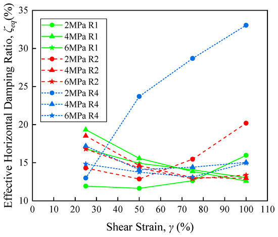
Figure 20.
The effective horizontal damping ratio of CBRB R1, R2 and R4.
As can be seen from Figure 19, the effective horizontal stiffness of the bearings decreases with increasing shear strain. In addition, the curves under a constant vertical pressure of 2 MPa (marked by circle) further decrease significantly, due to sliding of the bearing after the shear strain exceeding 50%. However, the reduction is not noticeable for the pressure of 4 MPa or 6 MPa (marked by triangle and pentagram, respectively). The effective horizontal stiffness of R2 increases with the increase of vertical pressure. When the vertical pressure of 4 MPa is applied, as the number of fabric layer increases, the effective horizontal stiffness of bearings also increases. Under the other two pressure levels, the above-mentioned conclusions cannot be obtained, and we will further study the specific reasons in the future research. As can be seen from Figure 20, when the shear strain is within 50%, its equivalent damping ratio decreases with increasing shear strain; as the shear strain is greater than 50%, its equivalent damping ratio changes without obvious rules, but the fluctuation is not large. However, the sliding of the bearing causes the effective horizontal damping ratio increase with increasing shear strain. In general, the effective horizontal damping ratio of this new type of bearings is about 15% without considering the sliding of the bearing.
Figure 21 and Figure 22 show the horizontal equivalent stiffness and the effective damping ratio of R2 and R3 at different shear strains and pressure levels. The legends in Figure 21 and Figure 22 have the same meaning as that in Figure 19 and Figure 20.
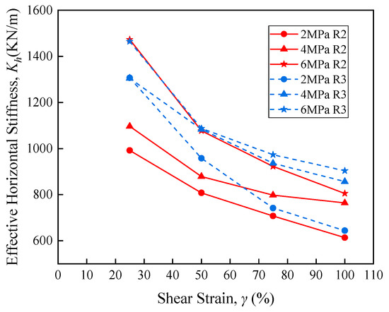
Figure 21.
The effective horizontal stiffness for Bearings R2 and R3.

Figure 22.
The effective horizontal damping ratio for Bearings R2 and R3.
Obviously, the effective horizontal stiffness and damping ratio of R3 are slightly larger than those of R2, but considering that the residual displacement of R3 during vertical compression is significantly larger, it is still not recommended for application in structures.
4.3. Ultimate Horizontal Shear Test
4.3.1. Description of the Test
After the horizontal compression-shear tests, the ultimate compression-shear test under a constant vertical pressure of 6 MPa was carried out on the bearing R1. Figure 23 shows the photographs of R1 taken from cyclic testing at different shear strains (γ = 50%, 100%, 150% and 200%). As the shear strain increased, the misalignment between the adjacent conveyor belts inside the bearing was obvious, and the bonding strength of the adhesive used for attaching gradually failed, until the test was terminated. When the shear strain is 150%, the side faces of the bearing were almost completely in contact with the upper and lower plates, and the interlayer dislocation was already obvious; when the second circle with 200% shear strain was applied, the restoring force of the bearing dropped by more than 20%, and the test was terminated. As can be seen from Figure 23, the quality of the cohesive is the key factor controlling the ultimate shear performance of this type of bearing.
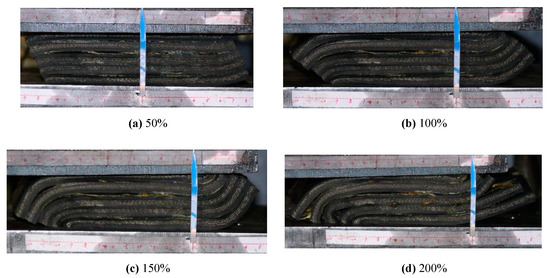
Figure 23.
Bearing R1 under limit horizontal shear test tests at different shear strains. (a) 50%; (b) 100%; (c) 150%; (d) 200%.
4.3.2. Mechanical Properties Analyses
The hysteretic curve, the effective horizontal stiffness and damping ratio of the R1 bearing under a constant vertical pressure of 6 MPa are shown in Figure 24, Figure 25 and Figure 26.
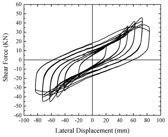
Figure 24.
Hysteretic curve of R1 in the ultimate compression-shear test.

Figure 25.
The effective horizontal stiffness of R1 in the ultimate compression-shear test.

Figure 26.
The effective horizontal damping ratio of R1 in the ultimate compression-shear test.
It can be seen from Figure 24 that the ultimate shear strain of this bearing is in the range from 150% to 200%. Figure 25 shows that, when shear strain γ is lower than 125%, the effective horizontal stiffness of the bearing decreases continuously, due to the rollover deformation; when the shear strain lies in the range from 125% to 150%, the side face of the bearing comes into contact with the upper and lower plates, the reduction in the stiffness slows down, and a hardening behavior is observed; unfortunately, as the shear strain is greater than 150%, the bonding strength of the cohesive gradually fails, which leads to a rapid decrease in the stiffness of the bearing, and failed to observe the further hardening behavior of the CBRB. Therefore, improving the bonding quality is an important target in the follow-up researches of this study. Figure 26 shows that the effective horizontal damping ratio of the bearing firstly decreases slowly with the increase of the horizontal shear strain, when the shear strain is greater than 150%, the bonding strength of the cohesive failed, causing a rapid growth in the damping ratio.
5. Conclusions
In this paper, fabric core conveyor belt rubber bearing (CBRB) with low cost and simple manufacturing process, and construction has been proposed, in order to improve anti-seismic capacities of low-rise buildings. The vertical compressive test and the horizontal compression shear test were carried out on four bearings, and the mechanical properties of each bearing obtained by the test were analyzed and compared. The concluding remarks are as follows:
- Under a vertical pressure of 4 Mpa, as the number of fabric core layer increases, the vertical stiffness of the bearings increases, while the damping ratio decreases. The minimum value of the vertical damping ratio is 6.3%. In the overpressure test, the vertical pressure of CBRB reached 10 MPa without damage.
- CBRB works very well within 100% shear strain. The horizontal stiffness of the bearings decreases with increasing shear strain. When the bearings do not slide, the effective horizontal damping ratio decreases with increasing shear strain, and the damping ratio is about 15%. The effective horizontal stiffness and damping ratio of the patterned bearing are slightly larger, but considering that its residual displacement during vertical compression is significantly larger, it is not recommended to be used in structures.
- In the ultimate horizontal shear test of CBRB, when the shear strain exceeds 150%, the interlayer dislocation within the bearing was already obvious. The reason is that the bonding quality between the conveyor belt layers limits the continued loading. The question of how to improve the bonding quality and the shear deformation capacity of CBRB will be the focus of subsequent researches.
- From the comprehensive view of the mechanical properties of CBRB, the bearing has low horizontal stiffness, good energy dissipation capacity, low cost and convenient production and construction. Therefore, it is very suitable for the earthquake-resistant construction of low-rise buildings in high intensity areas, to reduce the loss of life and improve property safety.
In the subsequent research, we will consider using the new bearing in a low-rise building through shaking table experiments and numerical simulations to further investigate the performance of the bearing in buildings.
Author Contributions
Y.W., Y.Z. and G.Z. conducted the experiment and writing, A.L. contributed to the discussion of the results. All authors discussed and agreed upon the idea and made scientific contributions. All authors have read and agreed to the published version of the manuscript.
Funding
This research was funded by the National Natural Science Foundation of China (grant No.51908024, No.51978033) and the Beijing Natural Science Foundation (grant No. 8194057). The APC was funded by the National Natural Science Foundation of China (grant No. 51908024).
Acknowledgments
This project is supported by the National Natural Science Foundation of China (Grant No.51908024, No.51978033), the Beijing Natural Science Foundation (grant No. 8194057). Finally, the authors would like to thank the two anonymous reviewers that helped to improve the final version of the article with their comments and suggestions.
Conflicts of Interest
The authors declare no conflict of interest.
References
- Chopra, A.K. Dynamics of Structures: Theory and Applications to Earthquake Engineering, 2nd ed.; Prentice-Hall: Upper Saddle River, NJ, USA, 2001; pp. 741–742. [Google Scholar]
- Van Engelen, N.C. Fiber-reinforced elastomeric isolators: A review. Soil Dyn. Earthq. Eng. 2019, 125, 105621. [Google Scholar] [CrossRef]
- Kelly, J.M. Analysis of fiber-reinforced elastomeric isolators. J. Seismol. Earthq. Eng. 1999, 2, 19–34. [Google Scholar]
- Moon, B.Y.; Kang, G.J.; Kang, B.S.; Kelly, J.M. Design and manufacturing of fiber reinforced elastomeric isolator for seismic isolation. J. Mater. Process. Tech. 2002, 130, 145–150. [Google Scholar] [CrossRef]
- Strauss, A.; Apostolidi, E.; Zimmermann, T.; Gerhaher, U.; Dritsos, S. Experimental investigations of fiber and steel reinforced elastomeric bearings: Shear modulus and damping coefficient. Eng. Struct. 2014, 75, 402–413. [Google Scholar] [CrossRef]
- Kang, B.S.; Kang, G.J.; Moon, B.Y. Hole and lead plug effect on fiber reinforced elastomeric isolator for seismic isolation. J. Mater. Process. Tech. 2003, 140, 592–597. [Google Scholar] [CrossRef]
- Toopchi-Nezhad, H.; Tait, M.J.; Drysdale, R.G. Testing and modeling of square carbon fiber-reinforced elastomeric seismic isolators. Struct. Contr. Health. Monit. 2008, 15, 876–900. [Google Scholar] [CrossRef]
- Toopchi-Nezhad, H.; Tait, M.J.; Drysdale, R.G. Lateral response evaluation of fiber-reinforced neoprene seismic isolators utilized in an unbonded application. J. Struct. Eng. 2008, 134, 1627–1637. [Google Scholar] [CrossRef]
- Toopchi-Nezhad, H.; Drysdale, R.G.; Tait, M.J. Parametric study on the response of stable unbonded-fiber reinforced elastomeric isolators (SU-FREIs). J. Compos. Mater. 2009, 43, 1569–1587. [Google Scholar] [CrossRef]
- Toopchi-Nezhad, H.; Tait, M.J.; Drysdale, R.G. Simplified analysis of a low-rise building seismically isolated with stable unbonded fiber reinforced elastomeric isolators. Can. J. Civ. Eng. 2009, 36, 1182–1194. [Google Scholar] [CrossRef]
- Toopchi-Nezhad, H.; Tait, M.J.; Drysdale, R.G. Bonded versus unbonded strip fiber reinforced elastomeric isolators: Finite element analysis. Compos. Struct. 2011, 93, 850–859. [Google Scholar] [CrossRef]
- Al-Anany, Y.M.; Tait, M.J. A numerical study on the compressive and rotational behaviour of fiber reinforced elastomeric isolators (FREI). Compos. Struct. 2015, 133, 1249–1266. [Google Scholar] [CrossRef]
- Van Engelen, N.C.; Osgooei, P.M.; Tait, M.J.; Konstantinidis, D. Partially bonded fiber-reinforced elastomeric isolators (PB-FREIs). Struct. Contr. Health Monit. 2015, 22, 417–432. [Google Scholar] [CrossRef]
- Van Engelen, N.C.; Tait, M.J.; Konstantinidis, D. Investigation of partially bonded fiber-reinforced elastomeric isolators (PB-FREIs) with nominal vertical tensile loads. Can. J. Civ. Eng. 2019, 46, 669–676. [Google Scholar] [CrossRef]
- Mordini, A.; Strauss, A. An innovative earthquake isolation system using fibre reinforced rubber bearings. Eng. Struct. 2008, 30, 2739–2751. [Google Scholar] [CrossRef]
- Das, A.; Deb, S.K.; Dutta, A. Shake table testing of un-reinforced brick masonry building test model isolated by U-FREI. Earthq. Eng. Struct. Dyn. 2016, 45, 253–272. [Google Scholar] [CrossRef]
- Thuyet, V.N.; Deb, S.K.; Dutta, A. Mitigation of seismic vulnerability of prototype low-rise masonry building using U-FREIs. J. Perform. Constr. Facil. 2017, 32, 04017136. [Google Scholar] [CrossRef]
- Al-Anany, Y.M.; Moustafa, M.A.; Tait, M.J. Modeling and evaluation of a seismically isolated bridge using unbonded fiber-reinforced elastomeric isolators. Earthq. Spectra. 2018, 34, 145–168. [Google Scholar] [CrossRef]
- Ashkezari, G.D.; Aghakouchak, A.A.; Kokabi, M. Design, manufacturing and evaluation of the performance of steel like fiber reinforced elastomeric seismic isolators. J. Mater. Process. Technol. 2008, 197, 140–150. [Google Scholar] [CrossRef]
- Dezfuli, F.H.; Alam, M.S. Performance of carbon fiber-reinforced elastomeric isolators manufactured in a simplified process: Experimental investigations. Struct. Contr. Health Monit. 2014, 21, 1347–1359. [Google Scholar] [CrossRef]
- Dezfuli, F.H.; Alam, M.S. Experiment-based sensitivity analysis of scaled carbon-fiber-reinforced elastomeric isolators in bonded applications. Fibers 2016, 4, 4. [Google Scholar] [CrossRef]
- Naghshineh, A.K.; Akyuz, U.; Caner, A. Lateral response comparison of unbonded elastomeric bearings reinforced with carbon fiber mesh and steel. Shock Vib. 2015, 1–10. [Google Scholar] [CrossRef]
- Naghshineh, A.K.; Akyuz, U.; Caner, A. Comparison of fundamental properties of new types of fiber-meshreinforced seismic isolators with conventional isolators. Earthq. Eng. Struct. Dyn. 2014, 43, 301–316. [Google Scholar] [CrossRef]
- Spizzuoco, M.; Calabrese, A.; Serino, G. Innovative low-cost recycled rubber-fiber reinforced isolator: Experimental test and finite element analyses. Eng. Struct. 2014, 76, 99–111. [Google Scholar] [CrossRef]
- Ping, T.; Kai, X.; Bin, W.; Fulin, Z. Performance study of isolated rural buildings using novel simple isolators. China Civ. Eng. J. 2013, 46, 64–70. [Google Scholar] [CrossRef]
- Hua, Z.; Tianbo, P.; Jianzhong, L.; Wenxiao, L. Experimental study of FRP rubber bearing. Adv. Mater. Res. 2011, 168, 1621–1624. [Google Scholar] [CrossRef]
- Menga, N.; Foti, D.; Carbone, G. Viscoelastic frictional properties of rubber-layer roller bearings (RLRB) seismic isolators. Meccanica 2017, 52, 2807–2817. [Google Scholar] [CrossRef]
- Shuai, C. Study on the Preparation and Properties of Cover Rubber Material for Ablation Resistant Conveyor Belt; Beijing University of Chemical Technology: Beijing, China, 2017; pp. 1–2. [Google Scholar]
- Gent, A.N. On the Relation between Indentation Hardness and Young’s Modulus. Rubber Chem. Technol. 1958, 31, 896–906. [Google Scholar] [CrossRef]
- Imbimbo, M.; De Luca, A.F.E. stress analysis of rubber bearings under axial loads. Comput. Struct. 1998, 68, 31–39. [Google Scholar] [CrossRef]
- Kelly, J.M. Analysis of the run-in effect in fiber-reinforced isolators under vertical load. J. Mech. Mater. Struct. 2008, 3, 1383–1401. [Google Scholar] [CrossRef][Green Version]
- Ministry of Transport of the People’s Republic of China. Code for Design of Highway Reinforced Concrete and Prestressed Concrete Bridges and Culverts; Ministry of Transport of the People’s Republic of China: Beijing, China, 2004; pp. 79–80.
© 2020 by the authors. Licensee MDPI, Basel, Switzerland. This article is an open access article distributed under the terms and conditions of the Creative Commons Attribution (CC BY) license (http://creativecommons.org/licenses/by/4.0/).