Article

Quasi-Static Characteristics and Vibration Responses Analysis of Helical Geared Rotor System with Random Cumulative Pitch Deviations

1
School of Mechanical Engineering, Xi’an Technological University, Xi’an 710021, China
2
School of Mechanical Engineering, Northwestern Polytechnical University, Xi’an 710072, China
*
Authors to whom correspondence should be addressed.
Appl. Sci. 2020, 10(12), 4403; https://doi.org/10.3390/app10124403
Submission received: 3 May 2020 / Revised: 22 June 2020 / Accepted: 24 June 2020 / Published: 26 June 2020
(This article belongs to the Section Mechanical Engineering)

Abstract

:
As one of the long period gear errors, the effects of random cumulative pitch deviations on mesh excitations and vibration responses of a helical geared rotor system (HGRS) are investigated. The long-period mesh stiffness (LPMS), static transmission error (STE), as well as composite mesh error (CMS), and load distributions of helical gears are calculated using an enhanced loaded tooth contact analysis (LTCA) model. A dynamic model with multi degrees of freedom (DOF) is employed to predict the vibration responses of HGRS. Mesh excitations and vibration responses analysis of unmodified HGRS are conducted in consideration of random cumulative pitch deviations. The results indicate that random cumulative pitch deviations have significant effects on mesh excitations and vibration responses of HGRS. The curve shapes of STE and CMS become irregular when the random characteristic of cumulative pitch deviations is considered, and the appearance of partial contact loss in some mesh cycles leads to decreased LPMS when load torque is relatively low. Vibration modulation phenomenon can be observed in dynamic responses of HGRS. In relatively light load conditions, the amplitudes of sideband frequencies become larger than that of mesh frequency and its harmonics (MFIHs) because of relatively high contact ratio. The influences of random cumulative pitch deviations on the vibration responses of modified HGRS are also discussed.

1. Introduction

Due to high power density, high reliability, as well as high transmission efficiency, gear transmission devices are widely applied to wind turbine, marine, automotive, and other industrial fields. Owing to manufacturing and heat treatment processes, which cause tooth displacement relative to its ideal position, manufacturing errors with various distribution forms and different magnitudes can be found in actual gears.
During the past several decades, a great deal of researchers have investigated the dynamic behaviors of spur/helical gear systems (in consideration of manufacturing errors) in published works. Gear errors consist of short and long period components. The short period gear errors were usually assumed as simple harmonic functions related to mesh frequency, the long period ones were regarded as a sine wave related to shaft frequency, and the time-varying mesh stiffness was regarded as a stiffness excitation which was independent with gear errors [1,2,3,4,5]. Moreover, when gear errors are introduced, the three-dimensional contact state of the tooth surface will differ under different load conditions. The phenomenon of partial contact loss may occur and lead to the changes of mesh stiffness and transmission error [6,7,8,9]. Hence, there is a nonlinear coupling relationship between mesh stiffness and gear errors because the contact patterns are dependent with load conditions.
The short period gear errors mainly include profile deviation, helix deviation, and gear modification. Mesh misalignment [10], which is caused by mounting errors and system deflection, is also regarded as a special short period gear error. Some scholars established the calculation models of load distribution [11,12,13,14], mesh stiffness, and transmission error [15,16,17,18] in consideration of short period gear errors, and further numerically and experimentally investigated the dynamic behaviors of gear system [19,20,21].
Cumulative pitch deviation is a very important and inevitable long period gear error. When introducing the long period gear error, the gear engagement processes will differ during different mesh cycles, and the system will be subjected to hybrid mesh excitations related to the mesh frequency and shaft frequency. In published works, considering cumulative pitch deviations, the determination of long period mesh excitations using three-dimensional contact analysis and dynamic behaviors analysis of gear system are rather rare. In recent years, few relevant research was conducted, and most of the research focused on the spur gear pair. Fernández [22] developed an enhanced model to study the influence of cumulative pitch deviation on load sharing ratio, as well as static transmission error (STE) and dynamic mesh forces of a spur gear pair. The results showed that index errors not only influence the vibration and noise, but also lead to high overloads. Talbot [23] and Inalpolat [24] employed a special test setup with transmission ratio of 1:1 to study the effect of tightly controlled intentional cumulative pitch deviations on the baseline vibration responses and vibration frequency spectrum of spur gear pairs. Moreover, Yuan [25] preliminarily investigated the influences of sinusoidal cumulative pitch deviations on mesh excitations and frequency spectrum of a helical gear pair.
In engineering practices, the pitch deviation values distributed over gear teeth usually has random characteristic because of manufacturing tolerance. For helical gear pairs, the number of teeth engaged at the same time is more than spur gear pairs. In addition, gear tooth flank is usually modified in order to reduce vibration. At this time, gear modification and cumulative pitch deviation have a comprehensive influence on tooth engagement process of helical gear pairs. Thus, the effects of cumulative pitch deviations on long period mesh excitations and vibration responses of the helical geared rotor system (HGRS) are much more complex. The relevant researches have not been reported in published works.
As the above analysis of the published research, the influence mechanism of cumulative pitch deviations on long period mesh excitations and vibration responses of the unmodified and modified HGRS is still unclear. It is necessary and important to investigate the changing law of long-period mesh stiffness (LPMS), STE, and composite mesh error (CMS) under the influence of random cumulative pitch deviations, and deeply explore the vibration spectrum characteristics of the unmodified and modified HGRS through introducing these long period mesh excitations, which are determined using three-dimensional contact analysis. The rest of this paper is organized as follows: Section 2 gives an enhanced loaded tooth contact analysis (LTCA) model of helical gear pairs with cumulative pitch deviations for determining LPMS, STE, and CMS, and establishes a multi degrees of freedom (DOF) dynamic model for HGRS using Timoshenko beam theory and finite element method. Section 3 gives some numerical results of mesh excitations and vibration responses of unmodified HGRS with random cumulative pitch deviations, and further analyzes the influence of random cumulative pitch deviations on the dynamic responses of modified HGRS. Section 4 draws some conclusions from the numerical results. The detailed flow chart of the study is given in Figure 1.

2. Description of the Models

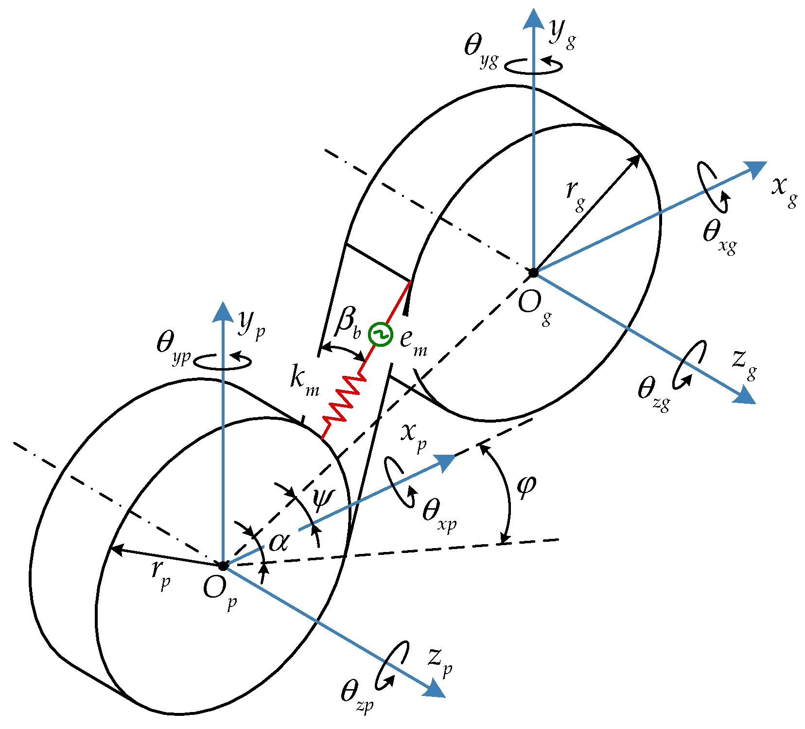
2.1. Calculation Model of Mesh Excitations for Helical Gears with Cumulative Pitch Deviations

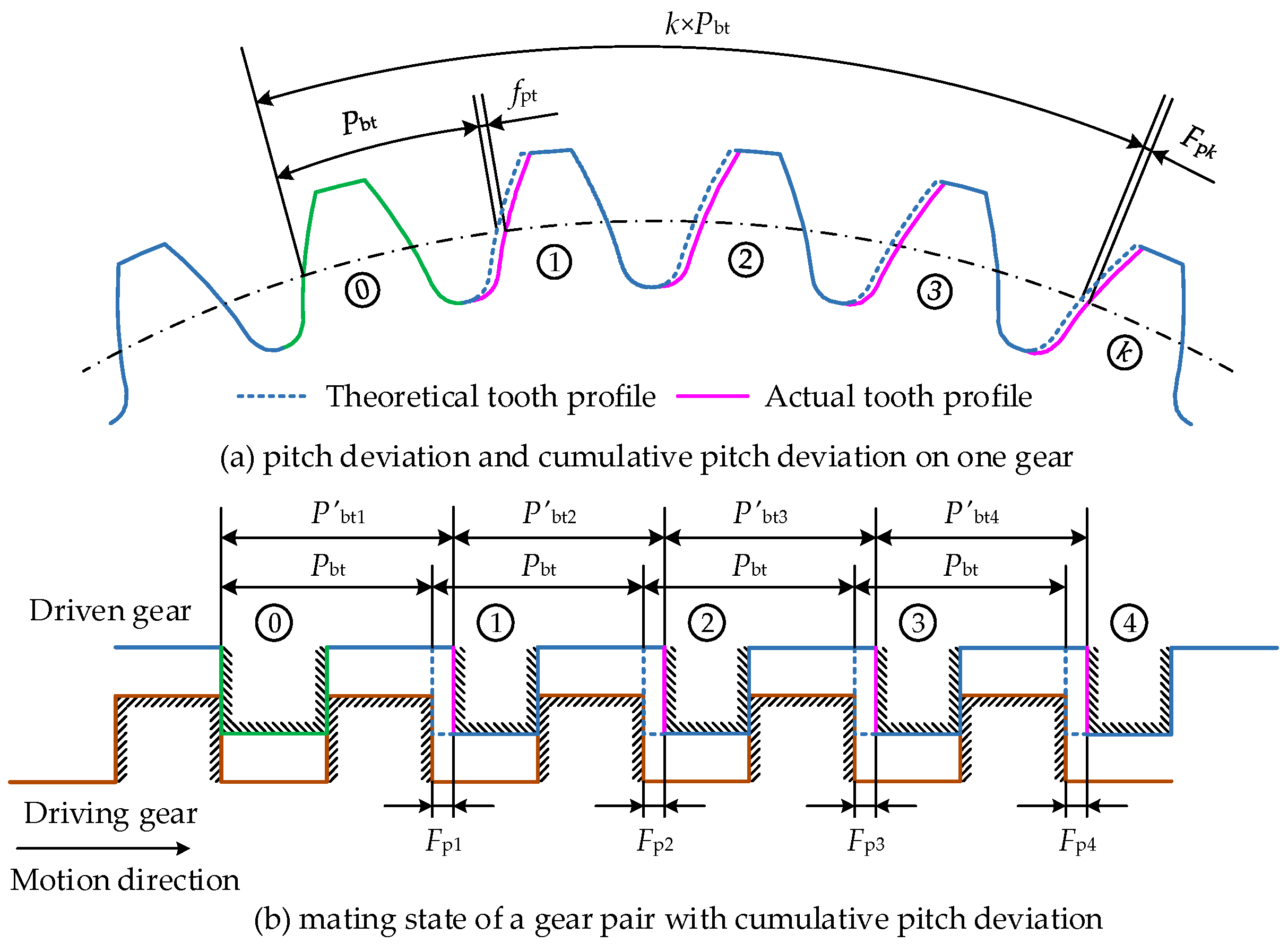
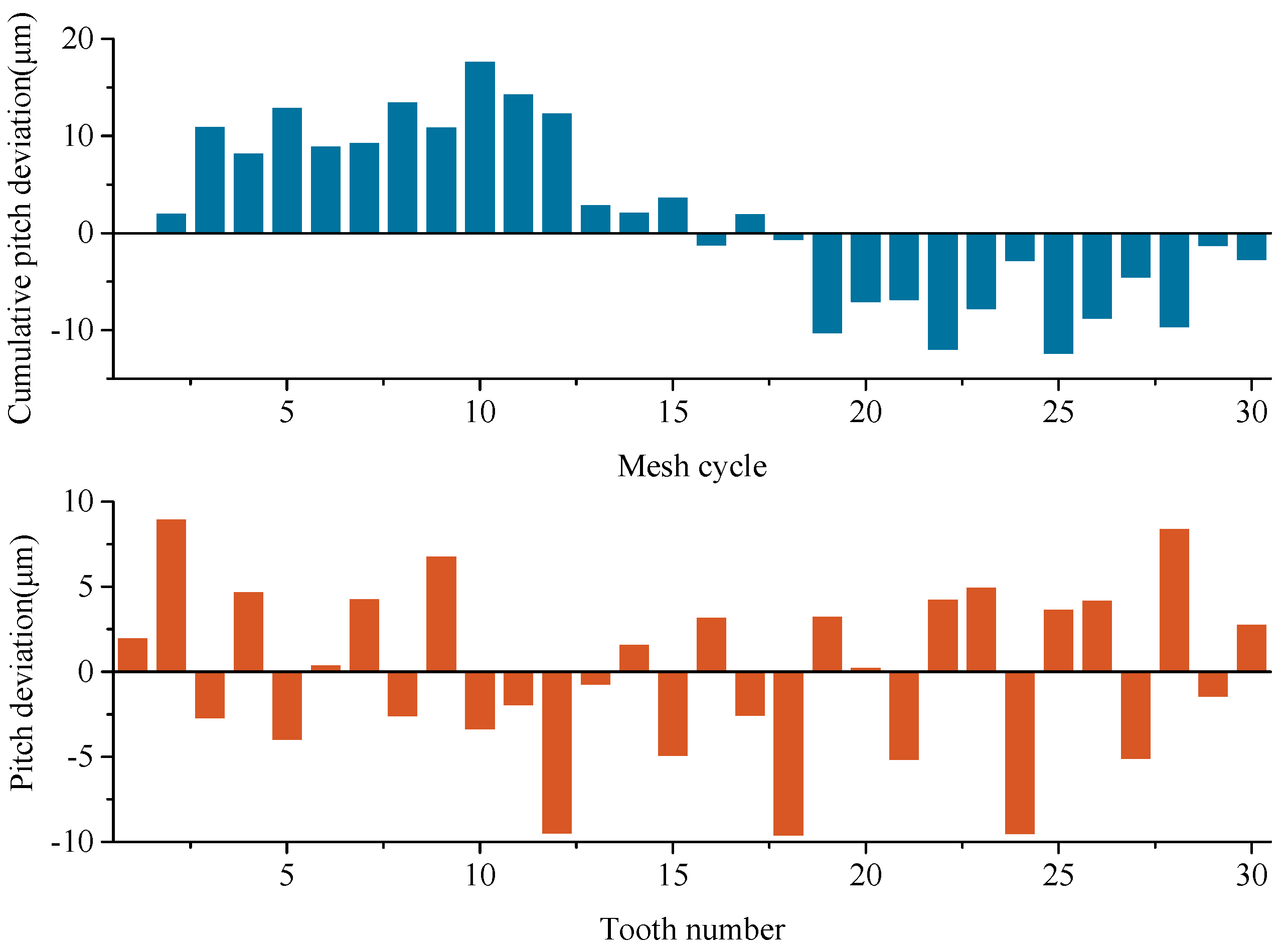
2.1.1. Description of Cumulative Pitch Deviations for Helical Gears

It is well known that cumulative pitch deviation and pitch deviation co-exist in actual gears. Pitch deviation denotes the circumferential position error of one tooth flank relative to the previous one. Cumulative pitch deviation refers to the algebraic difference between actual and theoretical arc length of any teeth spaces. Due to cumulative pitch deviations, the actual load sharing ratio between gear teeth is quite different from theoretical one. The phenomenon of overload or partial contact loss may occur in some potential contact region, and the actual contact ratio of the gear pair will be lower or higher than theoretical one.
Cumulative pitch deviation and pitch deviation are both measured along the tangential direction of standard pitch circle of gears. Figure 2a shows a helical gear with cumulative pitch deviations, and Figure 2b gives the mating state of the gear pair with cumulative pitch deviation when the contact tooth number is five in one engagement position. Here, the gear teeth numbered as zero is the reference tooth, P bt and f pt are theoretical tooth pitch and pitch deviation, respectively. P bt k and F p k are actual tooth pitch and cumulative pitch deviation for the gear tooth numbered as k, respectively. The pitch deviation f pt k of the k-th gear tooth is equal to the difference of two adjacent cumulative pitch deviations, it can be written as
f pt k = F p k F p ( k 1 )
In three-dimensional contact analysis model, the initial normal clearances between potential contact point pairs denote gear errors. The error values of cumulative pitch deviations and pitch deviations must be converted to the normal direction of tooth surface as follows
f pb n = f pt cos α t cos β b
where f pb n is the pitch deviation along the normal direction of gear tooth flank, α t is the transverse pressure angle, β b is the helix angle of helical gears.

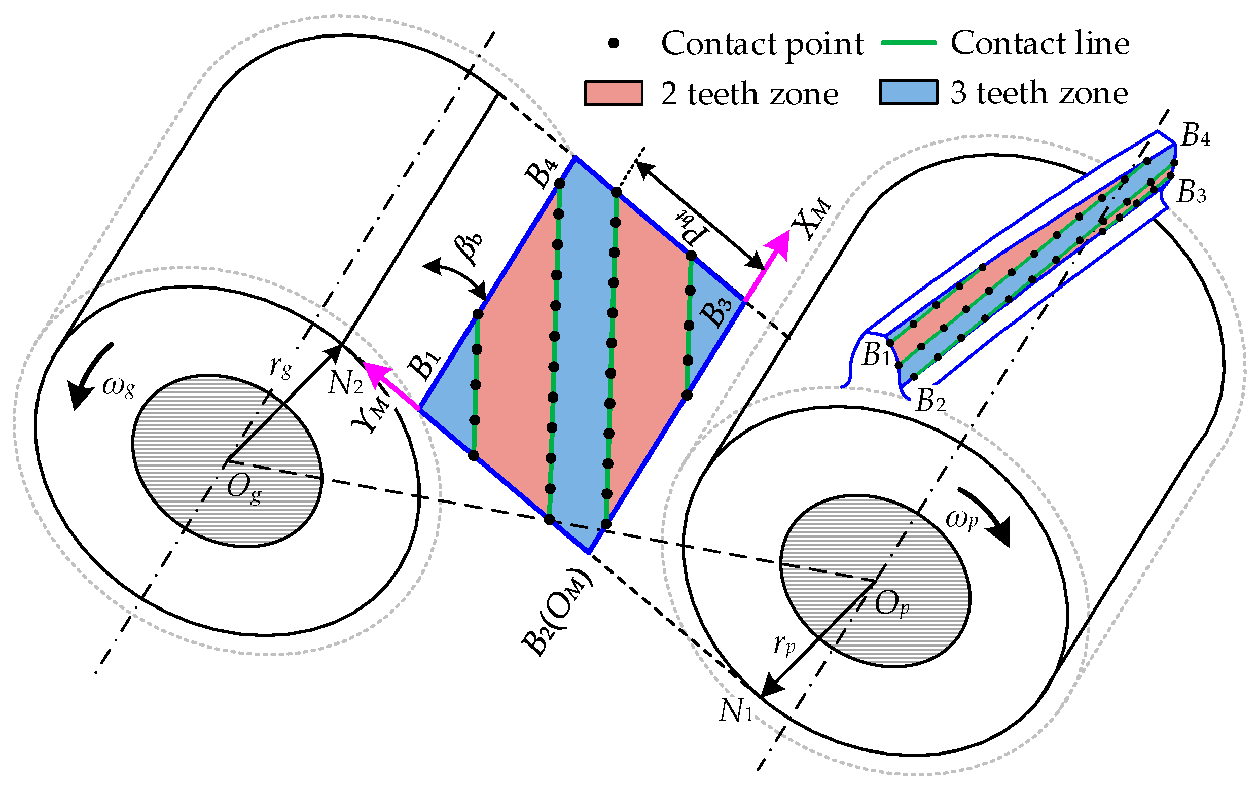
2.1.2. Determination of LPMS, STE, and CMS

In our previous work, a basic LTCA model with high computational efficiency has been developed [26]. It can be used to calculate the short period mesh stiffness and transmission error of a cylindrical gear pair with short period tooth flank errors. In this section, considering the difference of tooth engagement process in different mesh cycles and the actual engagement condition of each tooth pair, the basic LTCA model is extended to an enhanced LTCA model, which can be applied to the calculation of long period mesh excitations.
Figure 3 shows the enhanced LTCA model for a helical gear pair during one mesh cycle, and gives the arrangement of potential contact lines and contact points on plane of action (POA) B1B2B3B4. For a helical gear pair with total contact ratio of 2 to 3, it can be divided into 2 teeth and 3 teeth zone. rp and rg are the radius of base circle of driving and driven gear. Op and Og are the rotational center of the two gears. βb is helix angle of gear base circle. The rotational speeds of the two gears are denoted as ωp and ωg. The Cartesian coordinate system XMOMYM is defined for LTCA calculation. Figure 4 shows the initial contact condition of one contact line pair before load for unmodified and modified gear pairs in consideration of cumulative pitch deviations. fpbn1 and fpbn2 are the pitch deviations for driving and driven gear respectively, Mi1 and Mi2 are the modification values for contact point i on driving and driven gear.
In the LTCA model, the contact problem of gear tooth flanks in each engagement position is regarded as a line contact problem of two elastic bodies. Each contact line is evenly discretized into several contact points so that the line contact problem will be transformed into point contact problem. The gear errors on tooth flank will be introduced into potential contact point pairs as initial contact clearances. When the load torque is applied, the tooth flank of mating gear teeth will come into contact, and the gear deflections will occur.
Gear deflections consists of global deflections of mating gear teeth and local contact deformation of contact points. The global deflection changes linearly with the load, it can be determined using the flexibility matrix of contact points and loads on these contact points. The finite element substructure method can be employed to determine the global deflection flexibility of contact points [26]. The contact deformation of each contact point changes nonlinearly with the load, which can be calculated using analytical formula of contact deformation [15]. Introducing cumulative pitch deviations and tooth surface modifications into the initial clearances between contact point pairs, the contact condition of mating gear teeth in each engagement position can be expressed as [15]
{ [ δ G ] { F } + { χ C } + { ξ } S T E { ω } = 0 i = 1 n F i = P when   F i > 0 ,   ω i = 0 when   F i = 0 ,   ω i > 0
where [ δ G ] denotes the summation of flexibility matrix of the mating gear teeth, { F } refers to the load distribution vector on contact points after load, { χ C } is the contact deformations of contact points, { ω } is the residual clearances between contact point pairs after load, { ξ } is the initial clearances between contact point pairs before load. P is the normal force of gear pair.
For each engagement position, the nonlinear matrix Equation (3) can be solved using an iteration contact algorithm, which contains two control loops [26]. When the solutions in each engagement position of all mesh cycles are solved one by one, the long-period load distribution and STE will be determined.
The LPMS of helical gear pairs with cumulative pitch deviations can be determined using [15]
k m = i = 1 N k i = i = 1 N F i S T E ξ i
The CMS of helical gear pairs can be calculated using [15]
e m = 1 k m i = 1 N k i ξ i

2.2. Dynamic Model of HGRS

The research in this paper is aimed at cumulative pitch deviations, which have long periods, and the motivation is to study the influence mechanism of cumulative pitch deviations on the mesh excitations and vibration spectrum characteristics of HGRS. Thus, it is unnecessary to select complex gear transmission device, and a single stage gear system can satisfy the requirement. In the published researches, a single-stage gear transmission device with transmission ratio of 1:1 is used for several times [23,24,27,28,29]. In order to avoid too large s computational effort, according to those published works, a HGRS with transmission ratio of 1:1 is selected as the research object. Figure 5 shows the structure diagram of a HGRS. Shaft 1 and shaft 2 are solid shafts where the driving and driven gear are located. Both shafts are composed of several shaft segments with different diameters and lengths. The parameters of the helical gear pair are given in Table 1. Each shaft is composed of 5 shaft segments. The outer diameters of shaft segments of the two shafts from left to right are 70 mm, 90 mm, 110 mm, 90 mm, and 70 mm, respectively. For shaft 1, the length of shaft segments from left to right is 100 mm, 110 mm, 220 mm, 110 mm, and 60 mm, respectively. For shaft 2, the length of shaft segments from left to right is 60 mm, 110 mm, 220 mm, 110 mm, and 100 mm, respectively. Considering shaft structure, gear and bearing positions, each shaft is divided into 13 elements, as shown in Figure 5. Three basic elements (gear mesh element, shaft element, and bearing element) are used to build the dynamic model of HGRS.

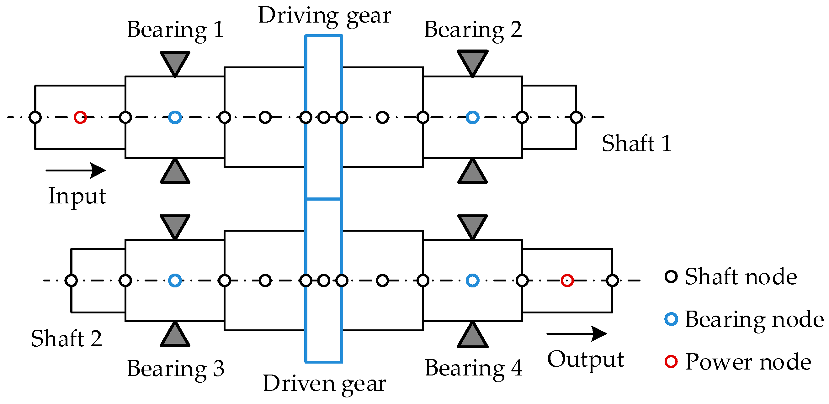
2.2.1. Element Models

Introducing spring and clearance, gear mesh element is used to simulate instantaneous engagement state of gear pairs. It consists of two nodes, each node has 6 DOF, as shown in Figure 6. The spring stiffness km refers to the LPMS, and the clearance em denotes the CMS. The two gears rotate around Op and Og. βb and α are the base helix angle and mesh angle. ψ is the phase angle.
The generalized coordinate vector of gear mesh element can be defined as
u m = { x p , y p , z p , θ x p , θ y p , θ z p , x g , y g , z g , θ x g , θ y g , θ z g } T
The relative displacement of driving and driven gear along normal line of action can be calculated using
τ m = T u m
where T can be expressed as
T = [ cos β b sin φ , cos β b cos φ , sin β b ,   r p sin β b sin φ , r p sin β b cos φ , r p cos β b , cos β b sin φ , cos β b cos φ , sin β b ,   r g sin β b sin φ , r g sin β b cos φ , r g cos β b ]
Based on the Newton motion law, introducing LPMS and CMS, the motion equations for gear mesh element can be written as
{ m p x ¨ p + [ c m τ ˙ m + k m ( τ m e m ) ] cos β b sin φ = 0 m p y ¨ p + [ c m τ ˙ m + k m ( τ m e m ) ] cos β b cos φ = 0 m p z ¨ p [ c m τ ˙ m + k m ( τ m e m ) ] sin β b = 0 I x p θ ¨ x p + [ c m τ ˙ m + k m ( τ m e m ) ] r p sin β b sin φ = 0 I y p θ ¨ y p + [ c m τ ˙ m + k m ( τ m e m ) ] r p sin β b cos φ = 0 I z p θ ¨ z p + [ c m τ ˙ m + k m ( τ m e m ) ] r p cos β b = 0 m g x ¨ g [ c m τ ˙ m + k m ( τ m e m ) ] cos β b sin φ = 0 m g y ¨ g [ c m τ ˙ m + k m ( τ m e m ) ] cos β b cos φ = 0 m g z ¨ g + [ c m τ ˙ m + k m ( τ m e m ) ] sin β b = 0 I x g θ ¨ x g + [ c m τ ˙ m + k m ( τ m e m ) ] r g sin β b sin φ = 0 I y g θ ¨ y g + [ c m τ ˙ m + k m ( τ m e m ) ] r g sin β b cos φ = 0 I z g θ ¨ z g + [ c m τ ˙ m + k m ( τ m e m ) ] r g cos β b = 0
where φ = α ψ , K m = k m V T V and C m = c m V T V .
The matrix form of Equation (8) can be expressed as
M m u ¨ m ( t ) + C m u ˙ m ( t ) + K m ( t ) [ u m ( t ) e m ( t ) ] = 0
where M m and e m ( t ) are mass matrix and CMS vector, respectively.
Timoshenko beam element is used to establish the dynamic model of shaft element, which includes 2 nodes with 12 DOF [15]. Ignoring the housing flexibility, bearing element is established using bearing stiffness and damping which connects shaft with foundation. In general, owing to the number change of loaded rollers, the stiffness of rolling bearing is usually time-dependent, whereas the published work shows that the numerical simulation results of a geared rotor system agree well with the experimental results when constant bearing stiffness is used. Thus, the time-dependent characteristic of the rolling bearing is neglected in this study. The stiffness matrix, damping matrix, and motion equation of bearing element can be found in [15].

2.2.2. System Model

When the dynamic model for each element is established, the finite element method is employed to assemble the element models according to the system structural parameters, and the dynamic model of the HGRS can be obtained, as shown in Figure 7.
The matrix form of motion equations of the HGRS can be expressed as
M G q ¨ G ( t ) + C G q ˙ G ( t ) + K G ( t ) [ q G ( t ) e G ( t ) ] = F G
where q G is the generalized coordinates of HGRS, M G , C G , K G are mass matrix, damping matrix and stiffness matrix of HGRS, respectively, e G denotes the CMS vector of HGRS, F G refers to load vector of HGRS.
In the actual operating condition, the gear pair is subjected to dynamic mesh force. For a spur gear system, it is easy to observe the strong nonlinear dynamic behavior (“jump” phenomenon), which is caused by tooth separations under resonant condition. However, for a helical gear system, the fluctuation of dynamic mesh force is far less than that of spur gear pairs owing to the much higher contact ratio. The published experimental work shows that strong nonlinear phenomenon (“jump” phenomenon) caused by tooth separations usually does not occur even under resonant condition for a helical gear system [21,30]. Moreover, it is suggested that the dynamic responses of a helical gear system, which is calculated by using quasi-static mesh excitations, is very close to the experimental results in the published works [15,30]. The research in this paper focuses on cumulative pitch deviations, which have a long period, and the established dynamic model of HGRS has large DOF. Considering the huge computational effort of the three-dimensional dynamic contact model and the conclusions in the published works [15,21,30], the quasi-static mesh excitations obtained from the enhanced LTCA model are used to predict the vibration responses of the HGRS.

3. Numerical Results and Discussion

In engineering practices, the cumulative pitch deviations with sine wave, which are used in published works [22,31], rarely occurs because of manufacturing tolerances. It is more practical to have random cumulative pitch deviations on gear teeth during one period of shaft rotation. Owing to the similarity between involute gear and involute spline, the random cumulative pitch deviations can be defined as the superposition of sine wave and normal distribution according to the generation mode of tooth indexing errors in the published research about involute spline [32]. Here, the normal distribution is employed to simulate the random characteristic of cumulative pitch deviations, i.e., λ ~ ( μ , σ 2 ) , where the mean value of cumulative pitch deviations μ = 0 μm, and the standard deviation σ = 3 μm. The schematic diagram of random cumulative pitch deviations and the corresponding pitch deviations are given in Figure 8. The amplitude of random cumulative pitch deviations is set to 15 μm.

3.1. Effect of Random Cumulative Pitch Deviations on Unmodified HGRS

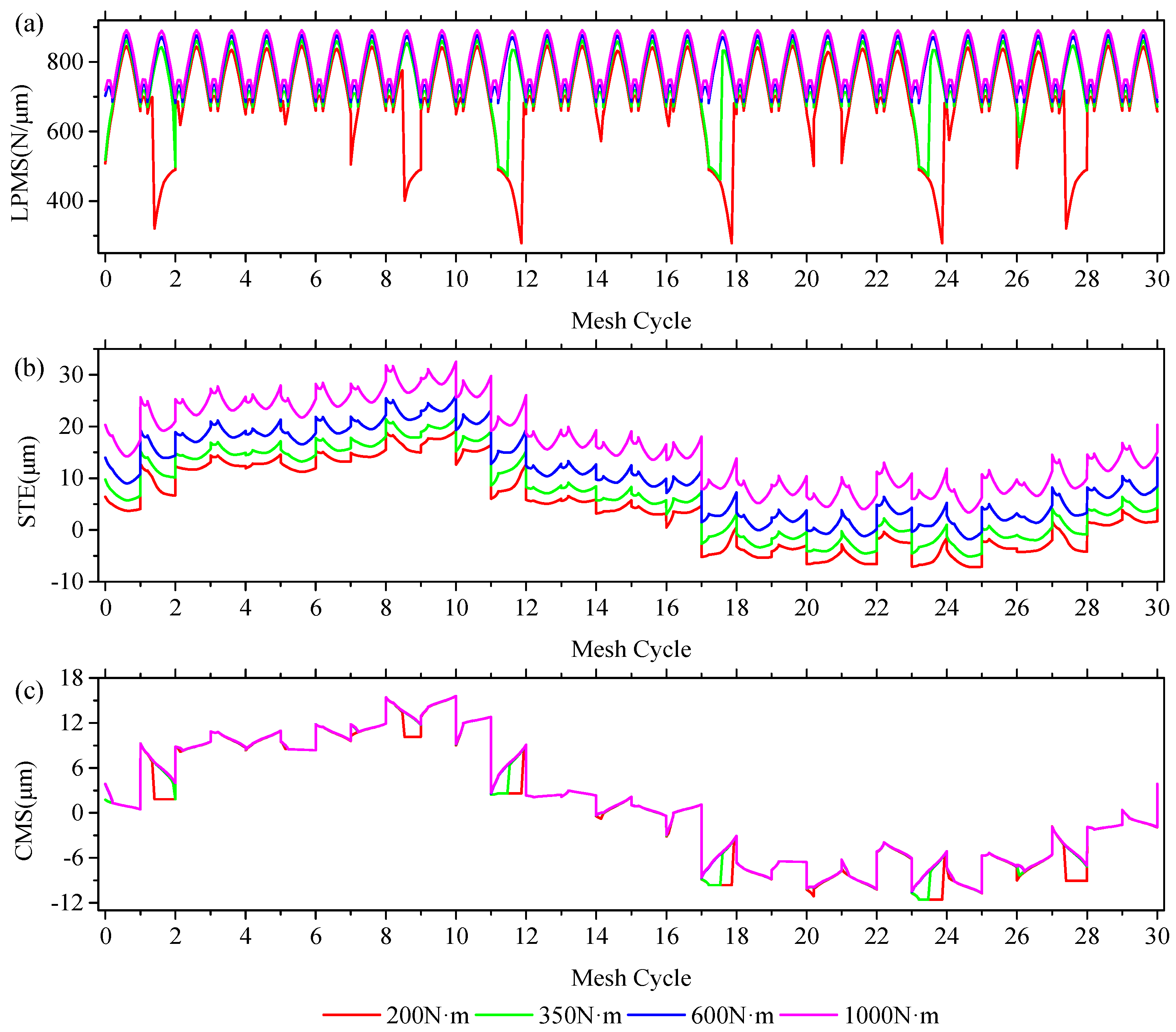
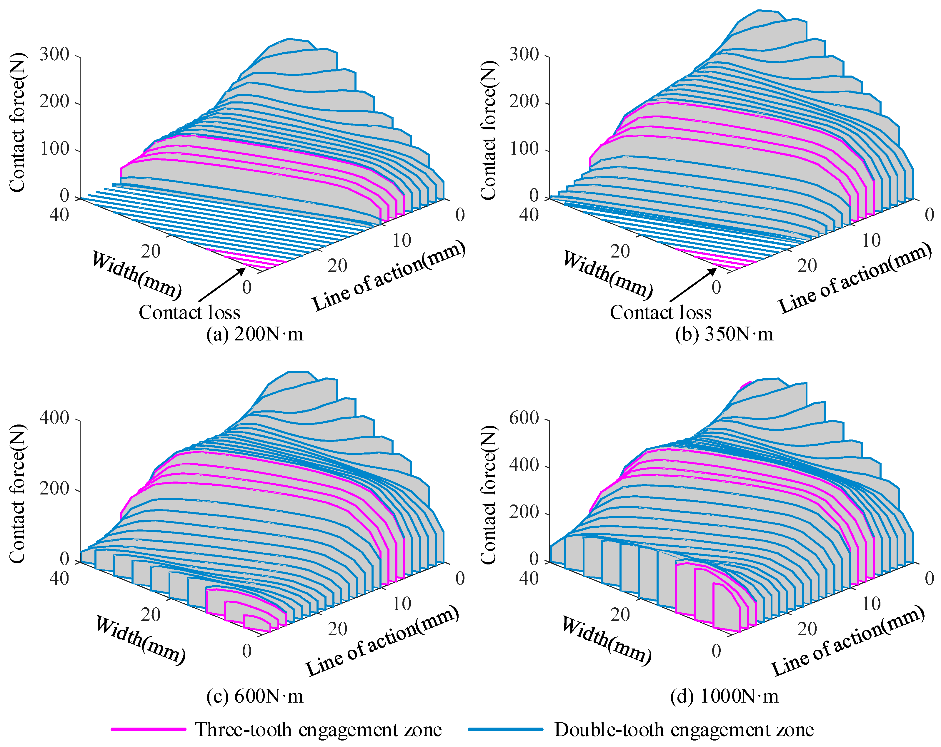
3.1.1. Quasi-Static Analysis

For a gear pair with manufacturing errors, the contact patterns will differ under different load conditions. The change of contact patterns will cause the changes of dynamic mesh excitations. In order to further analyze the vibration responses of the HGRS, the quasi-static mesh excitations of the helical gear pair with random cumulative pitch deviations are investigated in this section. LPMS, STE, and CMS of the helical gear pair with random cumulative pitch deviations under different load conditions are given in Figure 9. The load torques are 200 N·m, 350 N·m, 600 N·m, and 1000 N·m, respectively. It can be seen that the cumulative pitch deviations have significant influence on LPMS, STE, and CMS. From Figure 9a, it can be found that the values of LPMS under light load conditions in some mesh cycles are obviously smaller than that under heavy load conditions, and the corresponding curve shapes are notably different from each other. This is because partial contact loss occurs in these mesh cycles under relatively light load conditions. In Figure 9b, the shapes of STE curves under different load conditions are always consistent with each other, but the values become larger in each mesh cycle when the load torque increases. This is because the increased load torque results in larger tooth deflection which contributes to the STE values. From Figure 9c, it can be found that the CMS is related to the load condition. When the load torque is larger than 600 N·m, the curve of CMS remains constant. The changes of LPMS, STE, and CMS can be further explained from the remarkable change of corresponding load distribution. Figure 10 shows the load distributions in the twelfth mesh cycle at different load torques. It can be seen that partial contact loss occurs when the load torque is less than 600 N·m. Moreover, the contact loss region has a tendency to become smaller with the increase of load torque, and the mating gear teeth reaches full contact condition in each mesh cycle when load torque is larger than 600 N·m.

3.1.2. Dynamic Responses Analysis

Figure 11 shows the dynamic transmission errors (DTEs) of the helical gear pair with random cumulative pitch deviations under different load conditions. The load torques are also 200 N·m, 350 N·m, 600 N·m, and 1000 N·m, respectively. The input speed is 4000 r/min. It can be seen that the frequency spectrum becomes complex considering random cumulative pitch deviations. In frequency domain of DTEs, the amplitude of shaft frequency is the largest and the sideband frequencies around mesh frequency and its harmonics (MFIHs) appear. When the load torque is smaller than 600 N·m, the amplitudes of MFIHs are less than that of sideband frequencies f m ± i f s ( i = 1 , 2 , , n ) . With the increase of load torque, the amplitudes of MFIHs will be enhanced. The mesh frequency amplitude become larger than that of sideband frequencies when load torque is higher than 1000 N·m.
For bearing 1, the vibration acceleration along y direction at different load torques are shown in Figure 12. As similar as DTE, the frequency components of bearing vibration acceleration also become complex. The sideband frequencies f m ± i f s ( i = 1 , 2 , , n ) appear in the two sides of MFIHs. Some sideband frequencies are larger than mesh frequency when load torque is smaller than 600 N·m. As the load torque increases, mesh frequency amplitude will increase correspondingly. When the load torque is larger than 1000 N·m, the mesh frequency becomes the most predominant. Unlike DTEs, the shaft frequency is not the most predominant frequency in bearing vibration acceleration.

3.2. Effect of Random Cumulative Pitch Deviations on Modified HGRS

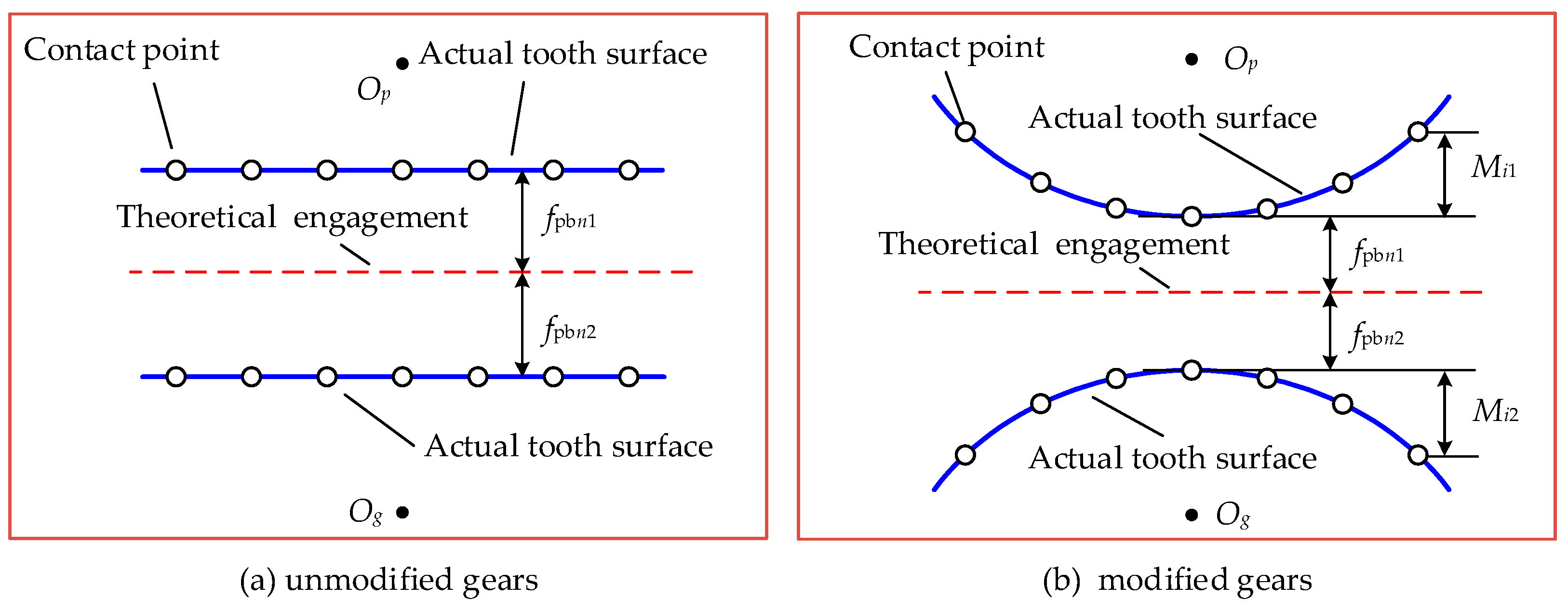
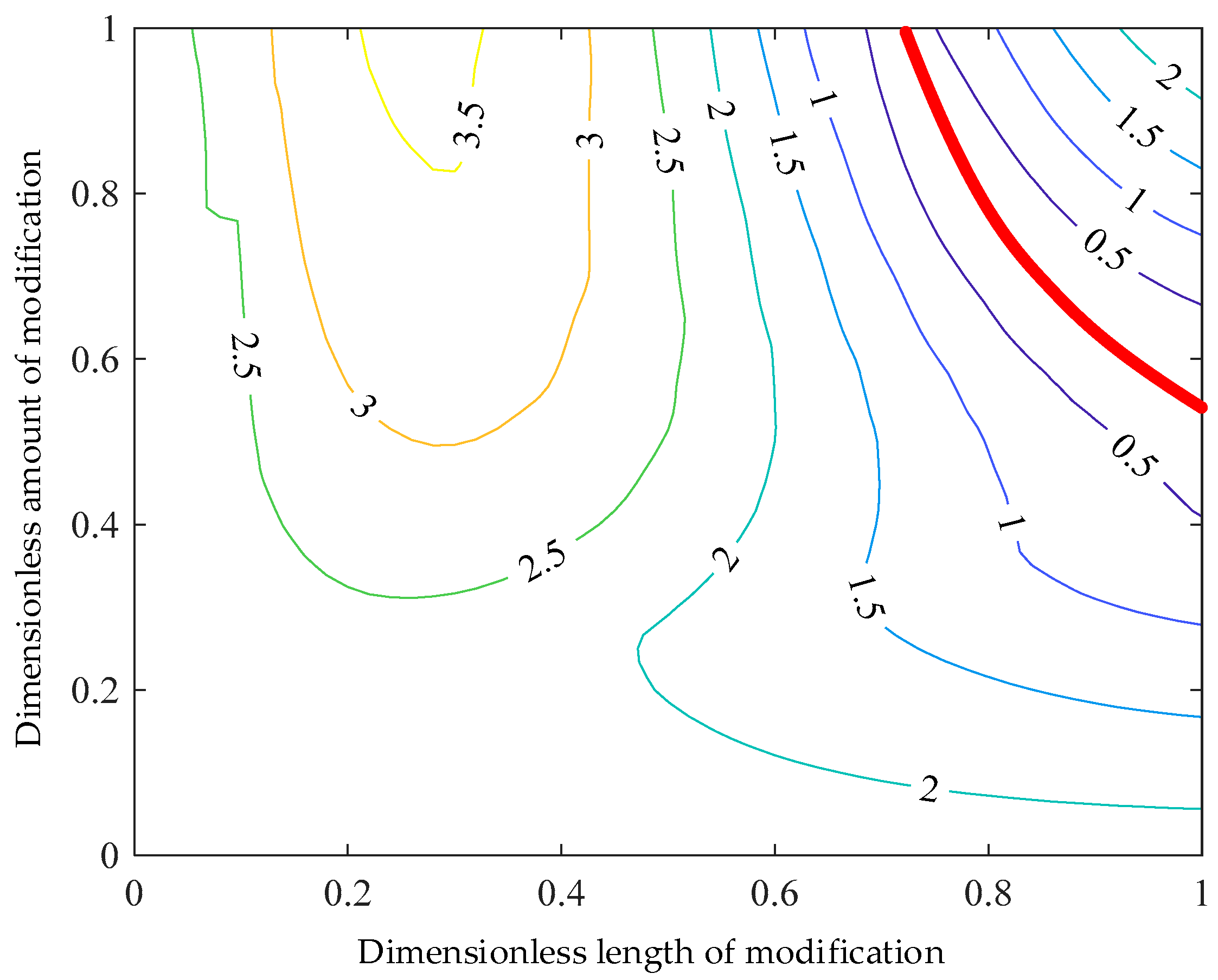
3.2.1. Design of Modification Parameters

It is generally known that the STE fluctuation is usually regarded as an effective standard to evaluate the vibration level of gear pairs. By reducing the material from the tooth top and tooth root, profile modification can change the curve shape and amplitude of transmission errors of a gear pair. When the amplitude of transmission errors is reduced, the vibration of the gear system will become weak. Profile modification has been widely used in the helical gear system [21,33,34]. Thus, it is necessary to understand the effect of random cumulative pitch deviations on the vibration responses of modified HGRS.
Figure 13 shows the design of profile modification for helical gears. Profile modification parameters include modification curve, amount of modification and length of modification. Both driving and driven gear are modified using tip relief. Based on POA, profile modification parameters are defined by the coordinate system XOY, and the potential maximum length of modification is B 1 B 2 , e max is the maximum amount of modification, L is the length of modification.
The modification curve adopts quadratic parabola. The equation of profile modification curve can be written as
{ e i = e max ( x i L L ) 2 , L x i 0 0 , W i d t h L > x i > L e i = e max ( x i Width + L L ) 2 , W i d t h x i W i d t h L
where x i is the distance from the contact point i to the starting position of profile modification, e i is the amount of modification for contact point i.
Because the enhanced LTCA model has very high efficiency, aiming to minimize the STE fluctuation, the optimal profile modification parameters can be obtained by brute global optimization method. This method can clearly show that the change law of STE fluctuation with the modification parameters [17]. The optimization scheme of profile modification is given in Figure 14. It can be observed that there is a narrow region for modification parameters (marked by red line) that reduce STE fluctuation significantly. The STE fluctuation in this region is less than 0.5 μm. From Figure 14, the optimal modification parameters can be obtained very conveniently.

3.2.2. Dynamic Responses Analysis

Considering random cumulative pitch deviations, the DTEs of the helical gear pair with and without profile modification are given in Figure 15. For the unmodified gear pair, the amplitude of shaft frequency in DTEs is the largest. Comparing Figure 15a with Figure 15b, it can be found that the amplitudes of MFIHs in DTEs decrease remarkably due to profile modification, but the corresponding sideband frequencies around MFIHs show a slight increasing trend. Considering random cumulative pitch deviations, for bearing 1, the vibration acceleration along y direction are given in Figure 16. As similar as DTEs, the amplitudes of MFIHs decrease significantly, but the amplitudes of sideband frequencies around MFIHs tend to be increased notably.
Considering different amplitudes of random cumulative pitch deviations, the root mean square (RMS) values of DTEs of the helical gear pair with and without profile modification are shown in Figure 17. The input speed changes from 25 r/min to 8000 r/min with a step of 25 r/min. For case 1 to case 4, the amplitudes of random cumulative pitch deviations are 0 μm, 5 μm, 10 μm, and 15 μm, respectively. From Figure 17a, it can be observed that the RMS values of DTEs of modified helical gear pair decrease significantly in all input speed conditions when compared with the unmodified gear pair. From Figure 17b, it can be found that profile modification shows a well effectiveness in reducing vibration of the HGRS when the input speed is less than about 5500 rpm, but the RMS values of DTEs of the modified gear pair are larger than that of unmodified one in some relatively higher input speed conditions. This is because the effects of random cumulative pitch deviations on dynamic responses are not the same in different input speeds due to natural frequencies of gear systems and frequency components of mesh excitations. As the amplitude of random cumulative pitch deviations increases, the influences of cumulative pitch deviations on the effectiveness of profile modification in reducing system vibration become more obvious. When the amplitude of random cumulative pitch deviations is larger than 10 μm, the vibration of the modified HGRS becomes stronger than that of the unmodified one in most input speed conditions, as shown in Figure 17c,d. Thus, as a long-period component of gear errors, cumulative pitch deviations not only affect the kinematic accuracy of gear pairs, but also have significant effect on vibration responses of HGRS.

4. Conclusions

In this paper, the influences of random cumulative pitch deviations on mesh excitations and vibration responses of HGRS are studied. The LPMS, STE, and CMS of helical gear pairs are determined using an enhanced LTCA model. A dynamic model with multi DOF is employed to predict the vibration responses of HGRS. The effect of random cumulative pitch deviations on vibration responses of modified HGRS in time and frequency domain are also investigated in detail. The main findings are summarized as follows:
(1)
considering random cumulative pitch deviations, the curve shapes of STE and CMS become irregular. When the load torque is relatively low, the LPMS in some mesh cycles will decrease due to partial contact loss. As the load torque increases, the actual contact region will become larger. When the contact patterns in each mesh cycle extend to full tooth surface, the curve shape of LPMS will become regular;
(2)
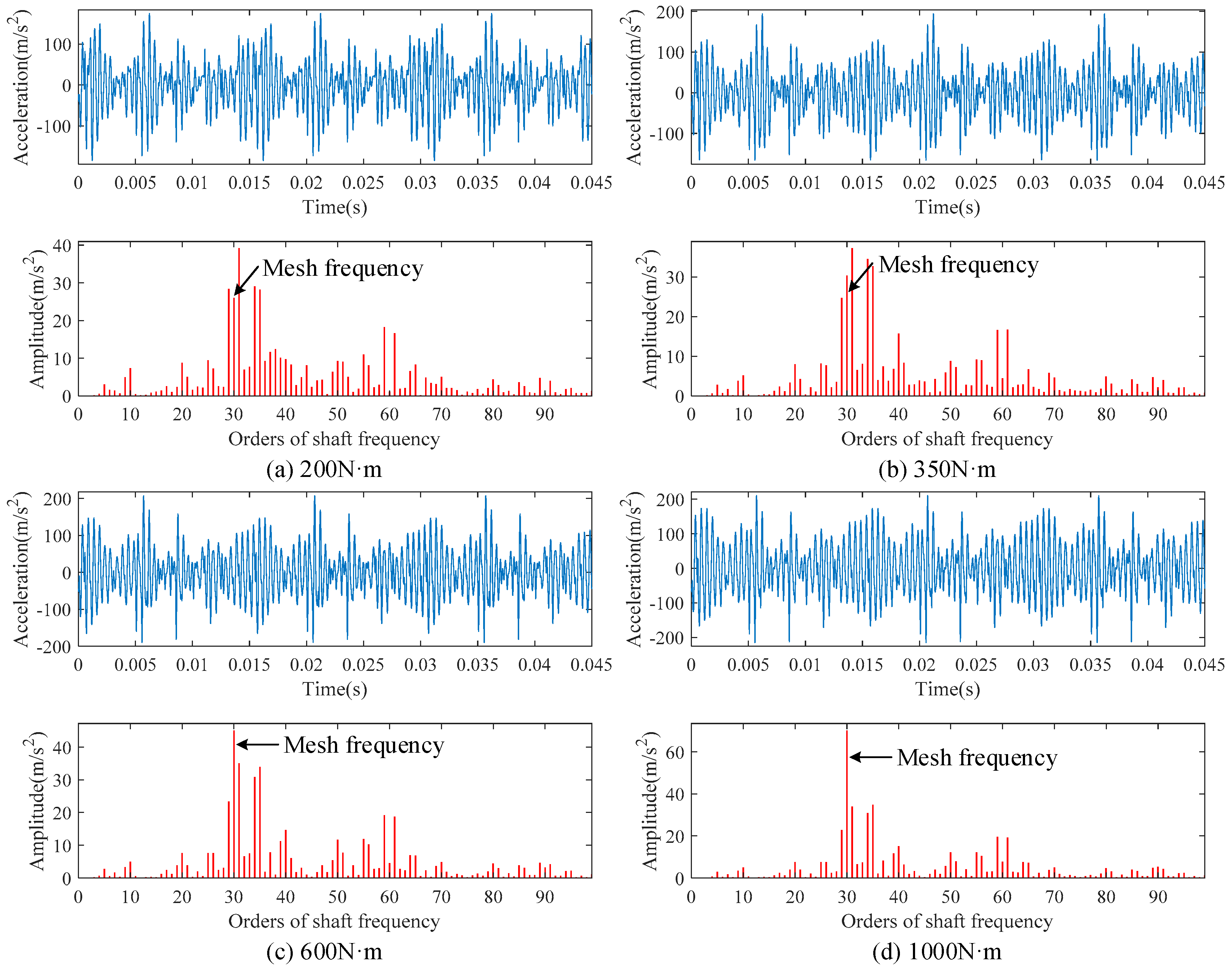
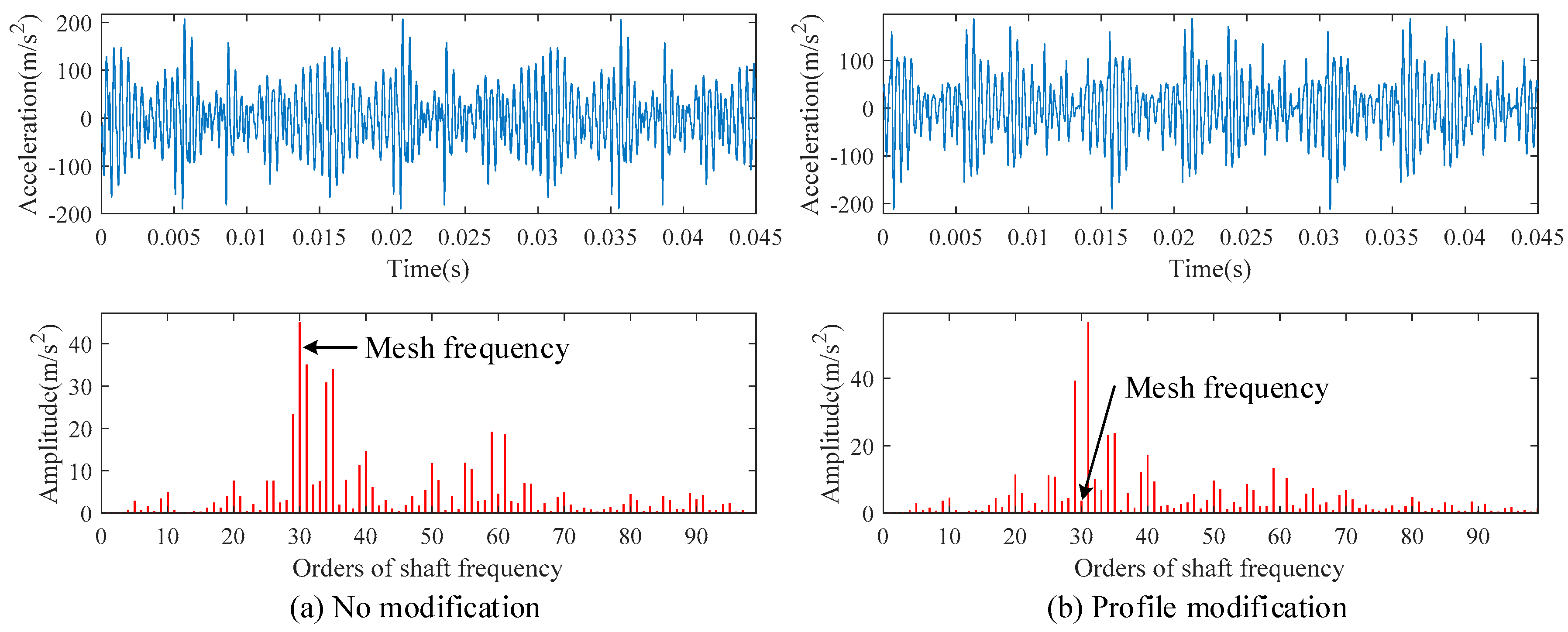
vibration modulation phenomenon can be observed in dynamic responses of HGRS with random cumulative pitch deviation, and the random characteristic of cumulative pitch deviations makes the vibration frequency spectrum complex. When HGRS is under light load conditions, the amplitudes of some sideband frequencies are larger than that of MFIHs because of relatively high contact ratio. With the increase of load torque, the amplitudes of MFIHs will increase and become larger than that of sideband frequencies;
(3)
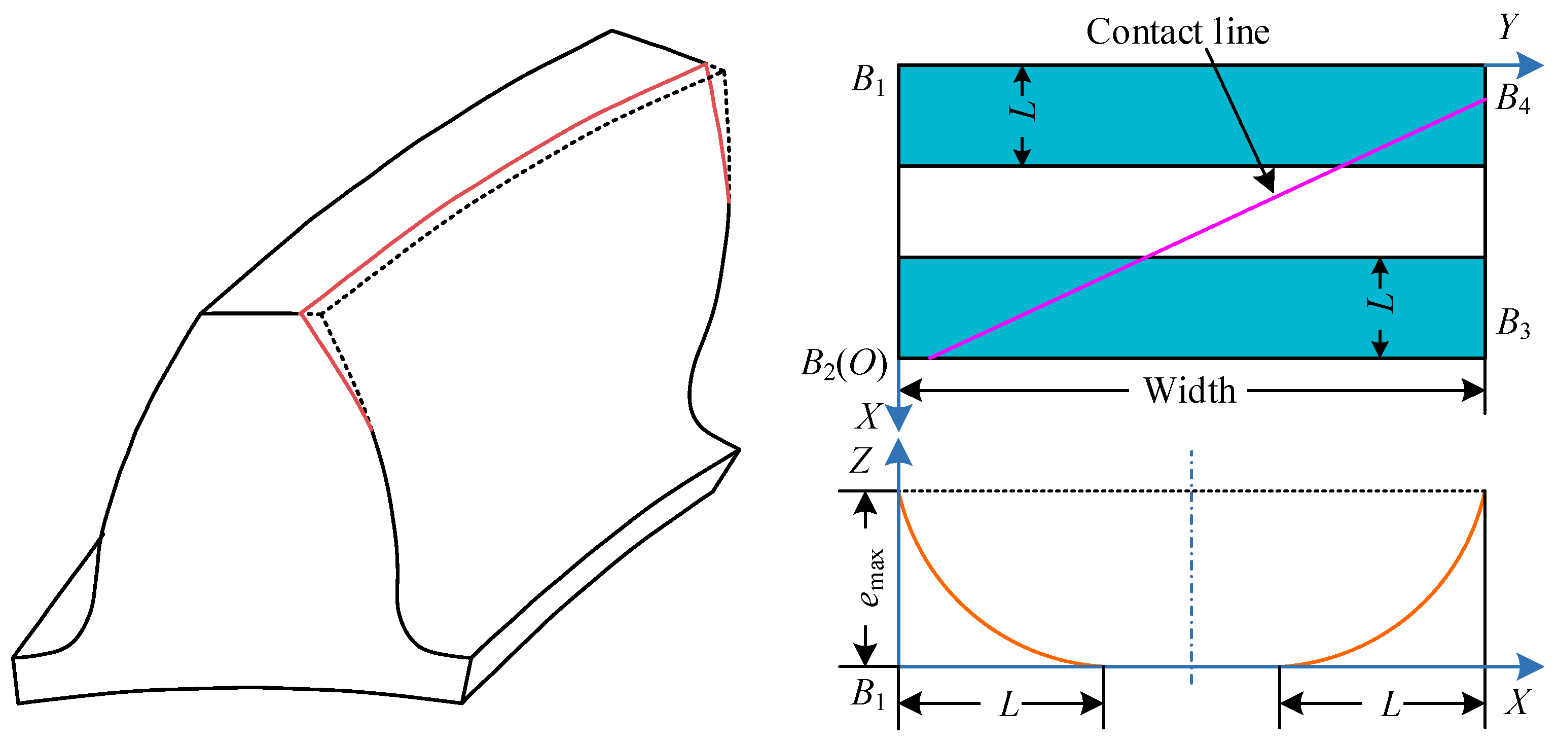
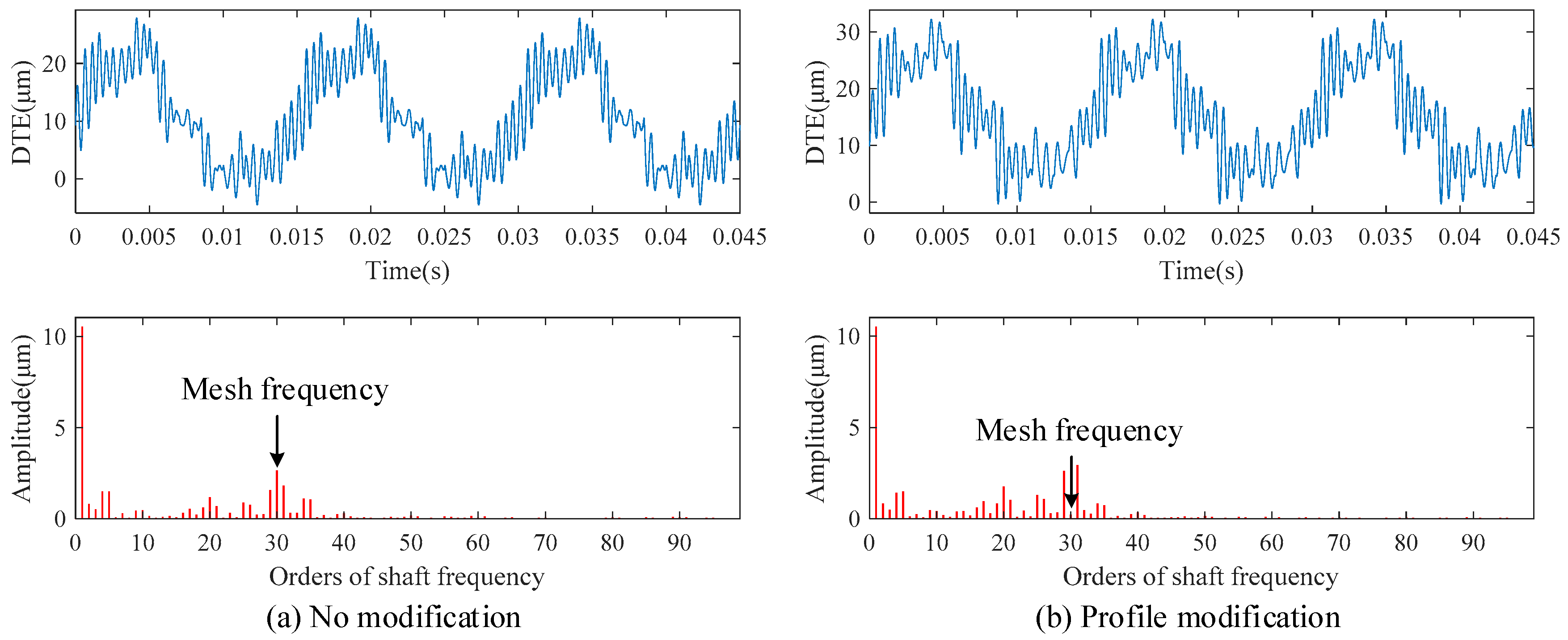
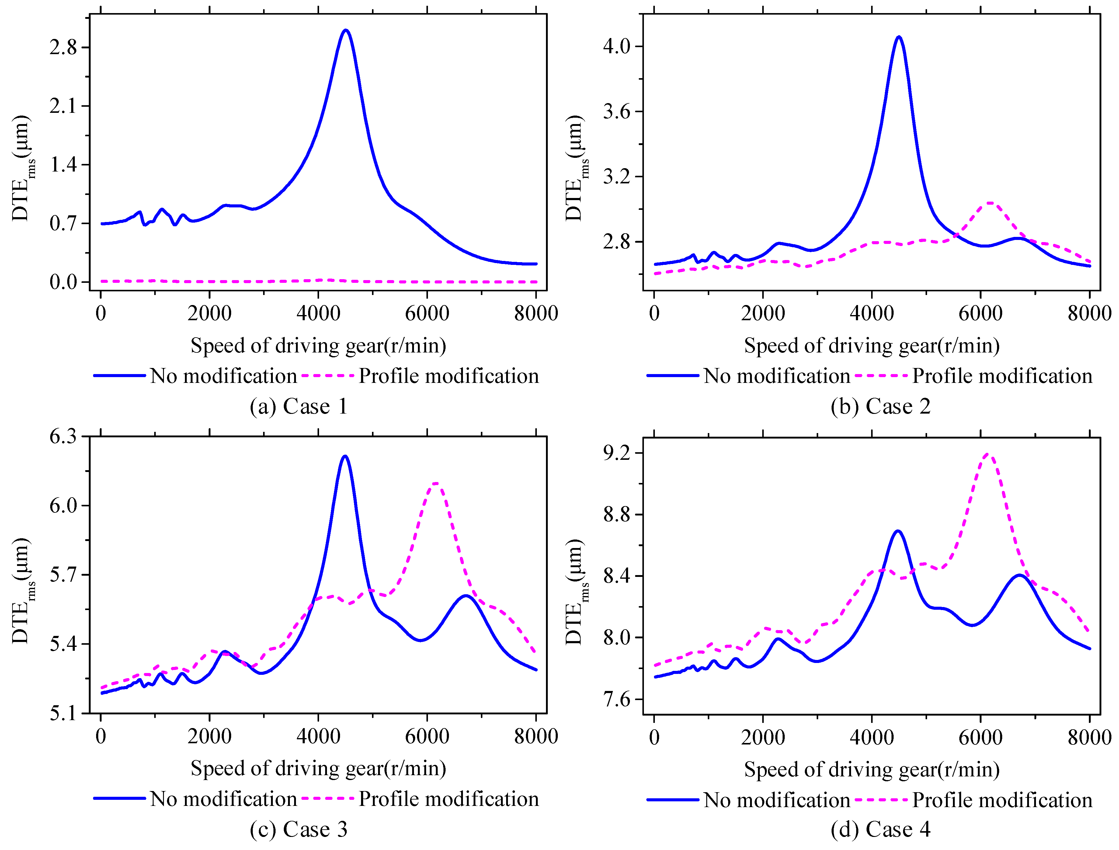
profile modification can reduce the amplitudes of MFIHs in DTEs and bear vibration acceleration. However, with the increase of the amplitude of cumulative pitch deviations, the effectiveness of profile modification in reducing system vibration will become weaker. In some working conditions, profile modification will lead to stronger system vibration for HGRS, owing to the increased amplitudes of sideband frequencies.

Author Contributions

Conceptualization, methodology, writing—original draft preparation, B.Y.; writing—review and editing, L.L.; funding acquisition, B.Y., G.L., and L.L. All authors have read and agreed to the published version of the manuscript.

Funding

This research was funded by National Natural Science Foundation of China (51535009), Natural Science Basic Research Program of Shaanxi (2020-JQ807), Scientific Research Program Funded by Shaanxi Provincial Education Department (20JK0677) and National Key R&D Program of China (2018YFB2001501).

Conflicts of Interest

The authors declare no conflict of interest.

References

  1. Byrtus, M.; Zeman, V. On modeling and vibration of gear drives influenced by nonlinear couplings. Mech. Mach. Theory 2011, 46, 375–397. [Google Scholar] [CrossRef]
  2. Yang, Y.; Cao, L.; Li, H.; Dai, Y. Nonlinear dynamic response of a spur gear pair based on the modeling of periodic mesh stiffness and static transmission error. Appl. Math. Model. 2019, 72, 444–469. [Google Scholar] [CrossRef]
  3. Chen, S.; Tang, J.; Luo, C.; Wang, Q. Nonlinear dynamic characteristics of geared rotor bearing systems with dynamic backlash and friction. Mech. Mach. Theory 2011, 46, 466–478. [Google Scholar]
  4. Yang, Y.; Xu, M.; Du, Y.; Zhao, P.; Dai, Y. Dynamic analysis of nonlinear time-varying spur gear system subjected to multi-frequency excitation. J. Vib. Control 2019, 25, 1210–1226. [Google Scholar] [CrossRef]
  5. Hu, Z.; Tang, J.; Zhong, J.; Chen, S. Frequency spectrum and vibration analysis of high speed gear-rotor system with tooth root crack considering transmission error excitation. Eng. Fail. Anal. 2015, 60, 405–441. [Google Scholar] [CrossRef]
  6. Ye, S.Y.; Tsai, S.J. A computerized method for loaded tooth contact analysis of high-contact-ratio spur gears with or without flank modification considering tip corner contact and shaft misalignment. Mech. Mach. Theory 2016, 97, 190–214. [Google Scholar] [CrossRef]
  7. Fernández-del-Rincón, A.; Iglesias, M.; de-Juan, A.; García, P.; Sancibrián, R.; Viadero, F. Gear transmission dynamic: Effects of tooth profile deviations and support flexibility. Appl. Acoust. 2014, 77, 138–149. [Google Scholar] [CrossRef]
  8. Li, S. Effects of misalignment error, tooth modifications and transmitted torque on tooth engagements of a pair of spur gears. Mech. Mach. Theory 2015, 83, 125–136. [Google Scholar] [CrossRef]
  9. Sánchez, M.B.; Pleguezuelos, M.; Pedrero, J.I. Influence of profile modifications on meshing stiffness, load sharing, and transmission error of involute spur gears. Mech. Mach. Theory 2019, 139, 506–525. [Google Scholar] [CrossRef]
  10. Kim, J.; Gang, G.A.; Cho, S.; Lee, G.H.; Park, Y.-J. Dynamic stiffness effect of mechanical components on gear mesh misalignment. Appl. Sci. 2018, 8, 844. [Google Scholar] [CrossRef] [Green Version]
  11. Wei, J.; Sun, W.; Wang, L. Effects of flank deviation on load distributions for helical gear. J. Mech. Sci. Technol. 2011, 25, 1781–1789. [Google Scholar] [CrossRef]
  12. Velex, P.; Maatar, M. A mathematical model for analyzing the influence of shape deviations and mounting errors on gear dynamic behaviour. J. Sound Vib. 1996, 191, 629–660. [Google Scholar] [CrossRef]
  13. Peng, Y.; Zhao, N.; Qiu, P.; Zhang, M.; Li, W.; Zhou, R. An efficient model of load distribution for helical gears with modification and misalignment. Mech. Mach. Theory 2018, 121, 151–168. [Google Scholar] [CrossRef]
  14. Shehata, A.; Adnan, M.A.; Mohammed, O.D. Modeling the effect of misalignment and tooth microgeometry on helical gear pair in mesh. Eng. Fail. Anal. 2019, 106, 104190. [Google Scholar] [CrossRef]
  15. Chang, L.; Cao, X.; He, Z.; Liu, G. Load-related dynamic behaviors of a helical gear pair with tooth flank errors. J. Mech. Sci. Technol. 2018, 32, 1473–1487. [Google Scholar] [CrossRef]
  16. Wang, Q.; Zhang, Y. A model for analyzing stiffness and stress in a helical gear pair with tooth profile errors. J. Vib. Control 2017, 23, 272–289. [Google Scholar] [CrossRef]
  17. Chen, Z.; Shao, Y. Mesh stiffness calculation of a spur gear pair with tooth profile modification and tooth root crack. Mech. Mach. Theory 2013, 62, 63–74. [Google Scholar] [CrossRef]
  18. Sun, Y.; Ma, H.; Huangfu, Y.; Chen, K.; Che, L.; Wen, B. A revised time-varying mesh stiffness model of spur gear pairs with tooth modifications. Mech. Mach. Theory 2018, 129, 261–278. [Google Scholar] [CrossRef]
  19. Wang, Q.; Ma, H.; Kong, X.; Zhang, Y. A distributed dynamic mesh model of a helical gear pair with tooth profile errors. J. Cent. South Univ. 2018, 25, 287–303. [Google Scholar] [CrossRef]
  20. Yuan, B.; Chang, S.; Liu, G.; Chang, L.; Liu, L. Optimization of bias modification and dynamic behavior analysis of helical gear system. Adv. Mech. Eng. 2017, 9, 3252. [Google Scholar] [CrossRef] [Green Version]
  21. Benatar, M.; Handschuh, M.; Kahraman, A.; Talbot, D. Static and dynamic transmission error measurements of helical gear pairs with various tooth modifications. J. Mech. Des. 2019, 141, 103301. [Google Scholar] [CrossRef]
  22. Fernández-del-Rincón, A.; Iglesias, M.; de-Juan, A.; Diez-Ibarbia, A.; García, P.; Viadero, F. Gear transmission dynamics: Effects of index and run out errors. Appl. Acoust. 2016, 108, 63–83. [Google Scholar] [CrossRef] [Green Version]
  23. Talbot, D.; Sum, A.; Kahraman, A. Impact of tooth indexing errors on dynamic factors of spur gears: Experiments and model simulations. J. Mech. Des. 2016, 138, 093302. [Google Scholar] [CrossRef]
  24. Inalpolat, M.; Handschuh, M.; Kahraman, A. Influence of indexing errors on dynamic response of spur gear pairs. Mech. Syst. Signal Process. 2015, 60–61, 391–405. [Google Scholar] [CrossRef]
  25. Yuan, B.; Chang, S.; Liu, G.; Wu, L. Quasi-static and dynamic behaviors of helical gear system with manufacturing errors. Chin. J. Mech. Eng. 2018, 31, 1–9. [Google Scholar] [CrossRef] [Green Version]
  26. Chang, L.H.; Liu, G.; Wu, L.Y. A robust model for determining the mesh stiffness of cylindrical gears. Mech. Mach. Theory 2015, 87, 93–114. [Google Scholar] [CrossRef]
  27. Zhang, Y.; Wang, Q.; Ma, H.; Huang, J.; Zhao, C. Dynamic analysis of three-dimensional helical geared rotor system with geometric eccentricity. J. Mech. Sci. Technol. 2013, 27, 3231–3242. [Google Scholar] [CrossRef]
  28. Handschuh, M.J.; Kahraman, A.; Milliren, M.R. Impact of tooth spacing errors on the root stresses of spur gear pairs. J. Mech. Des. 2014, 136, 061010. [Google Scholar] [CrossRef]
  29. Chen, Y. Time-varying dynamic analysis of a helical-geared rotor-bearing system with three-dimensional motion due to shaft deformation. Appl. Sci. 2020, 10, 1542. [Google Scholar] [CrossRef] [Green Version]
  30. Kubur, M.; Kahraman, A.; Zini, D.M.; Kienzle, K. Dynamic analysis of a multi-shaft helical gear transmission by finite elements: Model and experiment. J. Mech. Des. 2004, 126, 398–406. [Google Scholar] [CrossRef]
  31. Hu, Z.H.; Tang, J.Y.; Zhong, J.; Chen, S. Effects of tooth profile modification on dynamic responses of a high speed gear-rotor-bearing system. Mech. Syst. Signal Process. 2016, 76, 294–318. [Google Scholar] [CrossRef]
  32. Hong, J.; Talbot, D.; Kahraman, A. Effects of tooth indexing errors on load distribution and tooth load sharing of splines under combined loading conditions. J. Mech. Des. 2015, 137, 032601. [Google Scholar] [CrossRef]
  33. Wei, J.; Zhang, A.; Wang, G.; Qin, D.; Lim, T.C.; Wang, Y.; Lin, T. A study of nonlinear excitation modeling of helical gears with modification: Theoretical analysis and experiments. Mech. Mach. Theory 2018, 128, 314–335. [Google Scholar] [CrossRef]
  34. Bruyère, J.; Velex, P.; Guilbert, B.; Houser, D.R. An analytical study on the combination of profile relief and lead crown minimizing transmission error in narrow-faced helical gears. Mech. Mach. Theory 2019, 136, 224–243. [Google Scholar] [CrossRef]
Figure 1. Flow chart of the research framework and analysis process.
Applsci 10 04403 g001
Figure 2. End-side view and mating state of helical gear pair with cumulative pitch deviations.
Applsci 10 04403 g002
Figure 3. Enhanced loaded tooth contact analysis (LTCA) model of a helical gear pair during one mesh cycle.
Applsci 10 04403 g003
Figure 4. Initial contact condition before load in consideration of cumulative pitch deviations.
Applsci 10 04403 g004
Figure 5. Schematic diagram of HGRS.
Applsci 10 04403 g005
Figure 6. Dynamic model of gear mesh element.
Applsci 10 04403 g006
Figure 7. Dynamic model of HGRS.
Applsci 10 04403 g007
Figure 8. Definition of random cumulative pitch deviations and pitch deviations.
Applsci 10 04403 g008
Figure 9. Long-period mesh stiffness (LPMS), static transmission error (STE), and composite mesh (CMS) at different load torques considering random cumulative pitch deviations.
Applsci 10 04403 g009
Figure 10. Load distributions in the twelfth mesh cycle considering random cumulative pitch deviations.
Applsci 10 04403 g010
Figure 11. DTEs at different load torques considering random cumulative pitch deviations.
Applsci 10 04403 g011
Figure 12. Bearing vibration acceleration at different load torques considering random cumulative pitch deviations.
Applsci 10 04403 g012
Figure 13. Schematic diagram of profile modification for helical gears.
Applsci 10 04403 g013
Figure 14. Brute global optimization of profile modification (unit: μm).
Applsci 10 04403 g014
Figure 15. DTEs of modified and unmodified helical gear pair considering random cumulative pitch deviations.
Applsci 10 04403 g015
Figure 16. Bearing vibration acceleration along y direction considering random cumulative pitch deviations.
Applsci 10 04403 g016
Figure 17. DTEs versus input speeds under different random cumulative pitch deviations conditions.
Applsci 10 04403 g017
Table 1. Parameters of helical gear pair.
Number of Teeth30/30Addendum Coefficient1
Normal module/mm6Bottom clearance coefficient0.25
Pressure angle/°20Width/mm40
Helix angle/°±18

