Article

Performance and Modeling of a Two-Stage Light Gas Gun Driven by Gaseous Detonation

1
Key Laboratory of Microgravity (National Microgravity Laboratory), Institute of Mechanics, Chinese Academy of Sciences, Beijing 100190, China
2
School of Engineering Science, University of Chinese Academy of Sciences, Beijing 100049, China
3
State Key Laboratory of High Temperature Gas Dynamics, Institute of Mechanics, Chinese Academy of Sciences, Beijing 100190, China
4
Center of Materials Science and Optoelectronics Engineering, University of Chinese Academy of Sciences, Beijing 100049, China
*
Authors to whom correspondence should be addressed.
Appl. Sci. 2020, 10(12), 4383; https://doi.org/10.3390/app10124383
Submission received: 14 May 2020 / Revised: 20 June 2020 / Accepted: 23 June 2020 / Published: 25 June 2020
(This article belongs to the Special Issue The Advances in Fluid Mechanics)

Abstract

:
A two-stage light gas gun driven by gaseous detonation was newly constructed, which can make up for the disadvantages of the insufficient driving capability of high-pressure gas and the constraints of gunpowder. The performance of the gas gun was investigated through experiments and a quasi-one-dimensional modeling of it was also developed and described in detail. The model accounts for the friction and heat transfer to the tube wall for gases by adding a source term. An improved model has been established to consider the inertial loads in the piston or projectile and model the friction force with the tube wall. Besides, the effects of pump tube pressure on the performance of the gas gun are also investigated numerically. Simulations of the pressure histories in the pump tube and the piston and projectile velocities were conducted. A good agreement was observed between the computational predictions and experimental results. The results showed that the friction between the piston and wall had only small influence on the piston velocity. The proposed numerical approach is suitable for the development of two-stage light gas guns and tests of the operating conditions.

1. Introduction

A gasdynamic gun is a kind of test facility in which the test models or projectiles are launched at desired velocities and the aerodynamic properties of the flying models are measured during its flight, or shock and damage of the targets are measured upon the projectile impact [1]. With the invention of two-stage light gas gun by Crozier in 1946 and Hume in 1950s [2], especially hypervelocity ballistic range, was widely used in the fields of hypervelocity aerothermodynamics and hypervelocity impact effects as the results of development of hypervelocity reentry vehicles, protection of structures/shields against space debris, and kinetic energy weapons [3,4,5,6,7,8]. Although there are several other kinds of hypervelocity launchers, such as the electro-magnetic rail gun and coil gun, the two-stage light gas gun remains the most reliable and frequently used device in laboratories. Relative to other launchers, the two-stage light gas gun has advantages in considerable versatility, maturity of technology, low cost, and capability of launching test models of different shapes at hypervelocity.
Regardless of the driving method, the energy of the projectile depends on the energy that is stored in the driver section. Therefore, the driving method is of critical significance to the two-stage light gas gun. The simplest method is to utilize the high-pressure gas filled in driver section as the driver gas directly [9]. However, the driving capability of this method is not often sufficient, i.e., the available speed or energy of projectile is often not high enough to meet the experimental requirements within the range of operable pressure. This driving method is therefore mainly limited to situations requiring relatively low speed or energy for the projectile. To improve the driving capability, gunpowder is often used. Owing to the release of chemical energy, the driving capability of gunpowder is much more powerful than that of high-pressure gas. For example, the largest two-stage light gas gun in the world, the Arnold Engineering Development Complex (AEDC) Range-G, is capable of launching a projectile of 10 kg to speeds higher than 4 km/s [10]. Many studies of this driving method have been conducted, and relevant theories and numerical methods have been developed [6,11,12,13].
Although most large-scale two-stage light gas guns are currently driven by gunpowder, this driving method also has disadvantages. First, the transport, storage, and use of gunpowder are highly specialized activities and are restricted to strictly qualified organizations; therefore, the use of gunpowder is often out of reach for many research institutes. Second, it is a cumbersome task to clean the gunpowder residue after each run. Therefore, it is necessary to develop an alternative driving method that not only makes up the deficiency of driving capability of the high-pressure gas but also is more available and convenient compared to methods requiring gunpowder.
Gas guns driven by the combustion of flammable and explosive gases have been investigated as an alternative driving method. The combustion light gas gun that uses H2, O2, and He mixture gas as the driving gas was first developed by the UTRON Company [14]. It is capable of launching a projectile of 0.2 kg to speeds higher than 2.8 km/s. The China Aerodynamics Research and Development Center (CARDC) and McGill University also developed combustion two-stage light gas guns capable of a speed of 5.6 km/s [15]. Deng has developed an interior ballistics model of combustion light gas gun and found that the combustion process could be successfully controlled by adding the proper quantity of diluents. Pressure oscillation and average temperature of the chamber were also reduced [16,17,18]. However, the combustion light gas gun has difficulty in getting uniform and predictable ignition or muzzle velocities.
The detonation, a rapid and violent form of combustion, could serve as a high performance driver due to its rapid energy release in explosions. The detonation driver, which was first proposed by Bird [19] and has been applied to shock tunnels successfully [20], has also been suggested as the concept of “detonation products gun” [21]. The combustion products behind the detonation wave have much higher pressure and temperature than those of the initial state of the combustible mixture because of the strong compression produced by the leading shock wave with a Mach number range of 4 to 7. Subsequently, a single-stage gas gun driven by gaseous detonation was developed by Batchelor; the gas gun achieved velocities exceeding 3 km/s [22]. Li [23] discussed the internal ballistic process of a single-stage gas gun and verified its practical feasibility through experiments. Li also estimated the driving capability of a detonation driver for a two-stage light gas gun by solving the quasi-one-dimensional Euler equations; it was found that the detonation driver was sufficient to obtain projectile velocities of up to 8 km/s in a two-stage light gas gun. Unfortunately, experimental demonstrations and discussion of a two-stage gas gun driven by gaseous detonation are limited to date, nor its detailed numerical modeling. Obviously, numerical simulation is a simple method for the identification and assessment of new operating parameters of the test conditions without risk to the facility and hardware, as well as for the validation of new design concepts. It is also important for a detonation facility operating under the conditions of high temperature, high pressure, and presence of flammable and explosive gases.
In the present research, a two-stage light gas gun driven by gaseous detonation was newly constructed and is described in detail, including its piston and projectile measurements. A quasi-one-dimensional code is also developed to simulate the internal ballistics process. Viscous effects are incorporated by the well-known skin friction correlations for pipe flow. The friction force between the tube wall and the piston or projectile is considered by establishing an improved model that accounts for the inertial loads of the piston or projectile. Typical experiments are performed to validate the numerical method. Good agreements are obtained between the experimental and simulation results, including the piston/projectile velocity and pressure histories. The effect of parameters such as the pump tubes pressures on performance of the gun is also evaluated numerically.

2. Facility Description

2.1. Facility

This paper concerns the modeling and simulation of a particular newly built facility, namely the DBR30 two-stage light gas gun facility at the Institute of Mechanics Chinese Academy of Sciences (CAS). The facility consists of a detonation tube, a pump tube, a launch tube, and a target chamber, as shown in Figure 1. These components have inner diameters of 150 mm, 108 mm, 30 mm, and 1800 mm, respectively. The lengths of each section are shown in Figure 1.
Diaphragm I separates the detonation tube and the pump tube, and diaphragm II separates the pump tube and the launch tube; both are scored steel diaphragm. The grooves in the form of a cross with different depths are designed to adjust the critical rupture pressure of the diaphragm and minimize fragmentation. Diaphragm II is designed to have a rupture pressure of 45 MPa or 75 MPa in the present study. An ignition tube is placed at the upstream end wall of the drive tube. The mixture in the ignition tube is initially ignited by electrical sparks. A high-temperature jet is formed and propagating into the driving section, thereby igniting the detonable gas directly. This will lead to a stable detonation wave traveling downstream in the detonation tube, behind which a Taylor wave follows and the products are at high temperature and pressure.
Piezoelectric pressure transducers (CY-YD-211, made by SINOCERA PIEZOTRONICS, INC (Yangzhou, Jiangsu, China)), with a resonant frequency of more than 100 kHz, are mounted on the tube sidewall to record the pressure histories. The signals from the sensors are acquired by a signal conditioner and are processed on a PC-based data acquisition system at a sampling rate of 2 MHz. The transducers are labeled as P1 to P9 in the present study. P1 is located in the detonation tube and the others are placed in the pump tube. The origin of the coordinate system is located on the left side of the facility, and x-axis is in the longitudinal direction of the device. Thus, the coordinates of P1–P9 are x1 = 8.21 m, x2 = 10.55 m, x3 = 12.65 m, x4 = 18.65 m, x5 = 24.65 m, x6 = 28.25 m, x7 = 28.54 m, x8 = 30.54 m, and x9 = 30.83 m, respectively.

2.2. Piston and Projectile

The schematic drawing of the piston is shown in Figure 2. The front and rear part are made of polytetrafluoroethene (PTFE), which can prevent abrasion of the pump tube and minimize friction losses. The diameter of the piston at positions a, b, and c in Figure 2 is 108 + (0.1–0.2) mm at room temperature before the experiments. The diameter at position d is manufactured to be 108 + (0.5–0.9) mm, which can prevent gas leakage from the pump tube to the detonation tube and make full use of the compressed light gas. Although the piston will freeze before the experiments, the diameter at position d can still satisfy a close fit with the pump tube. To further minimize friction losses, the diameter of the piston is locally reduced as shown in Figure 2. The deformable front and rear parts of the piston have a weight of 4.114 kg and 0.774 kg, respectively, and they are replaced after each test. The PTFE surrounds a steel metallic weight, with a diameter of 105 mm. The length of the steel weight is selected in order to change the weight of the piston and influence the compression process. In the present study, a steel weight of 5.552 kg is selected. Thus, the total weight of the piston is 10.44 kg, with a total length of 680 mm.
Due to the geometric variation in the longitudinal direction as the piston moves past the piezoelectric transducers, the pressure around the sensors and the voltage of the piezoelectric transducers change. Typical pressure periods as the piston move past the sensors P3 and P8 are shown in Figure 3. Points d, e, and f in Figure 3 represent time when the corresponding point on the piston passes the sensor. In Figure 3a, the rising of the pressure at point d indicates the passing of the piston, as well as the arrival of the high pressure detonation gas. For the pressure sensors at the right section of the pump tube, they are already exposed to the high pressure light gas at the arrival of the piston. There are significant pressure changes due to the geometric variation in the longitudinal direction of the piston, as shown in Figure 3b. Thus, the pressure histories can be used to calculate the piston velocities at different positions.
Different shapes and weights of projectile can be used in the gas gun. However, only the muzzle velocity value and the measuring method are described here. A laser diagnostic system and high-speed photography were used to measure the projectile velocity. The laser diagnostic system can measure the projectile muzzle velocity directly, while the high-speed photography is an auxiliary method to verify the accuracy of the results of the laser diagnostic system results. The photography optical window is 3320 mm away from the launch tube exit. The snapshots in Figure 4 demonstrate the high-speed photography results processed by a script written in Python that incorporates edge detection and shape fitting methods. The velocity of the projectile is calculated using Equation (1):
v p r o = Δ d Δ t R p r o R r e d
where Δd is the distance between the center of the red circle in two images, Δt is the time interval between two sequential frames, i.e., 13.3 μs in the present case; Rpro and Rred are the radius of the actual projectile and the radius of the red circle in the image, respectively. Rred and Δd have the unit of pixel and their values are related to the resolution of the high-speed camera. However, their values are detected from the images and have no influence to the actual projectile velocity calculation. The projectile in the present is a cylinder with a spherical head, as shown in Figure 4, and the diameter of the sphere is 30 mm.

3. Numerical Modeling

3.1. Governing Equations

Numerical simulations are necessary to understand the gas-dynamic processes and piston or projectile movement, and they are straightforward and provide detailed information. A simulation is also a simple method to identify and assess new operating parameters of the test conditions without risk to the facility and hardware, as well as for the validation of new design concepts. The two-stage gas gun driven by detonation involves detonation, flow of gas, motion of the piston and projectile, energy dissipation, and other complex chemical and physical phenomena. A two-dimensional axisymmetric investigation of the tube flows by solving the unsteady Navier-Stokes equation coupled with the heat conduction equation would be a more appropriate method. However, modeling all phenomena in detail is unrealistic in this method. For example, it is challenging to simulate the strong interactions between the detonation waves and the main diaphragm. In addition, the computer resources and simulation time are extensive, even for simple shock tube cases, not to mention the detonation tubes where complicated chemical reactions occur. Thus, a quasi-one-dimensional code is more attractive for the engineering design in the present study.
The flow of gas is modeled by the quasi-one-dimensional equations, and the detonation process in the drive gas is described by the two-step chemical reaction model modified by Sichel et al. [24]. The equations, written in conservation form, are
A U t + A F x A x H S c A S w = 0
where the state vector U = (ρ, ρu, e, ρα, ρβ)T, the flux vector F = (ρu, ρu2 + p, (e + p)u, ραu, ρβu)T, the chemical reaction source term Sc = (0, 0, 0, ω ˙ α , ω ˙ β )T, the wall pressure source term H = (0, p, 0, 0, 0)T, and the wall-friction and heat-transfer source term Sw = (0, τ, q, 0, 0)T; where ρ, u, e, p, and A are the density, velocity, total energy, and pressure of the gas, and the cross-sectional area, respectively. τ is the wall shear stress and q is the wall heat flux. α and β, which are associated with the two-step chemical reaction model describing the detonation process, are the process parameter of the chemical induction and the chemical transformation, respectively; ω ˙ α and ω ˙ β are the rates of the chemical induction and the chemical transformation, respectively. For the details of this model, please refer to Ref. [24]. For the oxyhydrogen detonation, eight components, H2, O2, HO, H2O, H2O2, HO2, O, and H, are taken into account in the computations, and for the methane-oxygen detonation, CH4, CO2, and CO are added. Based on this chemical reaction model and the dispersion controlled dissipation scheme proposed by Jiang [25], a code has been developed and successfully applied to the simulations of detonation-driven shock tubes [26].
The situation of the two-stage gas gun differs from that of the shock tube due to the presence of the piston and projectile. To account for the effect of the piston or projectile on the gas flow, the motion of it is treated as the moving boundary conditions for the governing Equation (2). The acceleration of the piston or projectile is calculated from its mass and the applied force. Since the acceleration of the gas at the base and front of the piston or projectile is the same as the piston or projectile itself, and the disturbance resulting from the motion of the piston or projectile to the gas is isentropic if the displacement of the piston or projectile is small enough within each time step, the equations along characteristics and isentropic process still hold [11]. Thus, the sound speeds and pressures at these locations are obtained. The other state quantities are calculated in terms of the equations of state and of sound speed. Provided that the boundary condition is determined, Equation (2) can be solved as routinely as that for the detonation-driven shock tube.
The piston or projectile is assumed to have a fixed mass, length, and cross-section area. Their states are given by a flag whether they are constrained, its tail positions xp, xm, and velocities vp, vm. Subscript “p” represents the piston, and “m” represents the projectile throughout this paper. Since the process of the piston and projectile are described using the same method, only the governing differential equations are displayed here.
d v p d t = 1 m p ( A p ( p B p F ) F f )
d x p d t = v p
where pB and pF are the pressures acting on the back and front faces of the piston, respectively.

3.2. Gas-Phase: Friction and Heat Transfer Terms

Although the boundary layer along the tube wall is not completely modeled in the formulation of the gasdynamic equations, its effects are modeled by the addition of a wall shear stress in the momentum equation and heat transfer in the energy equation.
The wall-skin stress on the gas is given by: τ = −0.5πu|u|D. The skin friction coefficient for the pipe flow is then computed as [12]:
{ f = 0.049 ( Re D ) 0.2 Re D 5507 f = 0.00875 5507 Re D 1828 f = 16 Re D 1828 Re D
f = f T T is evaluated at the reference temperature as follows: T = 0.9 T + 0.03 M 2 T + 0.46 T w , where T is the cell temperature and Tw is the specified wall temperature, M is the Mach number. The Reynolds number is calculated as: Re D = ρ u D μ , where u is the cell velocity and D is the tube diameter of the cell. ρ and μ are evaluated at the reference conditions: ρ = ρ T T , μ = μ ( T , ρ ) .
The heat transfer from the gas to the walls is given by: q = h π D ( T w T ) , where the heat transfer coefficient is h = ρCp|u|St and the Stanton number is given by the modified Reynolds analogy for pipe flows [27]:
S t = f 8 Pr 2 3
In the treatment of the viscous gas mixture, Wilke’s mixture rule is applied with Maxwell’s Power Law to calculate the dynamic viscosity of the gas [28]:
μ = μ 0 ( T T r e f ) n       n = 0.76   ( air )   or   0.83   ( detonation   gas )
According to Ref. [27], the Prandtl number is given approximately as:
Pr = 20 γ 39 γ 15
where γ is the ratio of the specific heat for gases.

3.3. Friction between Piston and Wall

The implementations in the L1d code assume that the friction force is simply proportional to the pressure exerted either at the back or the front of the piston, and that the piston is a perfectly elastic body [27]. However, this method is specified not from physical considerations, but to produce the best agreement between the calculated and experimental values of object velocity or gas pressure. An improved model with a physical basis has been implemented for the Longshot by accounting for the inertia loads within the piston [29]. Since different types of pistons are used in different facilities; modifications were made based on the Longshot method to obtain a better agreement in the present study. Details are described below.
The longitudinal stresses σx of a moving piston are obtained by considering successive static stresses (due to equal pressures applied on both ends of the piston) and dynamic stresses (due to the remaining pressure difference and the corresponding acceleration of the piston). The longitudinal stresses within a piston in arbitrary motion are then obtained by summing the static contribution and the dynamic one, as expressed by Equation (9).
σ x = min ( p b , p f ) + 4 F i n e r t i a π D 2
where D is the diameter of the piston, Finertia = mp|ap| are the piston inertia forces during the acceleration.
According to Hook’s law generalized to cylindrical coordinates, the strain–stress relationship in an isotropic medium are:
ε r = 1 E ( σ r ν ( σ θ + σ x ) )
ε θ = 1 E ( σ θ ν ( σ r + σ x ) )
where E is Young’s modulus of the material, σx and εr are the radial stresses and strain, σθ and εθ are the azimuthal stresses and strain.
For the specific case where the piston is bounded by the tube, only axial and radial deformations are allowed. As long as the diameter of the piston is larger than that of the tube, differences in the diameter ∆r exist between the piston and tube, and then the radial and angular strains are obtained as follows:
ε r = u r r Δ r R p = 2 Δ r D p
ε θ = u r r + 1 r u θ θ Δ r R p = 2 Δ r D p
where Rp is the radius of the piston, and Dp is the diameter.
Thus, the radial stress can be obtained from Equations (9)–(13). Besides, an upper limit for the local stresses σr may be associated to the maximum stresses allowable before yield would take place.
σ r = min ( σ y i e l d , 2 E Δ r D p ( 1 ν ) + ν 1 ν ( min ( p b , p f ) + 4 F i n e r t i a π D t 2 ) )
The normal force FN corresponding to the radial stresses applied on all friction surfaces of the piston is defined as:
FN = σr πDpLf
where Lf is the length of the piston in contact with the tube. The friction force Ff is then assumed to be proportional to the normal force FN:
Ff = μf FN
The piston consists of PTFE and its Poisson’s ratio ν is 0.4; the sliding friction coefficient μf of steel-PTFE is in the range of 0.04–0.05. Young’s modulus is about 0.5 GPa, and the yield stress is about 20 MPa [30].
At room temperature, the diameter of the piston is manufactured to be larger than that of the tube. However, freezing of the piston at 0 °C for at least four hours before the experiments is required to be able to insert the piston into the tube. Since time is needed to pump the tubes and fill them with the initial gas, the experiments are usually finished 30 to 50 minutes after the piston has been inserted. Figure 5 shows the changes in the piston diameter during the thawing process at room temperature. Positions a to d on the piston are illustrated in Figure 2. A positive ∆r indicates a tight fit between the piston and pump tube, and a negative ∆r means a loose fit. Positions a, b, and c still have negative ∆r values after 60 minutes, while position d has positive values. Thus, only the rear end of the piston contacts with the pump tube; hence, Lf is set to 30 mm in the computation. Since the diameter of the rear part changes gradually, as shown in Figure 2, the diameter at its center position is used to deduce ∆r. The diameter at position d is 108 + (0.5–0.9) mm. Thus, ∆r is set to 0.25–0.45 mm in the calculation. It will become evident in the following discussion that these values do not have a significant influence on the modeling results.

4. Results and Discussion

Three particular test cases were selected from the available data, and the key parameters are listed in Table 1, including the projectile velocity from the experimental and computational fluid dynamics (CFD) results. Initial gas temperature was 293 K. However, in case 3, the system failed to capture the projectile velocity. The projectile velocity was measured at an optical window 3320 mm downstream of the launch tube exit. Since the pressure in the target chamber was usually set to a low pressure in the order of several kilo Pascal. It is assumed that the projectile speed has no significant attenuation.

4.1. Grid Independence Study

A grid convergence study was conducted using the above numerical method with three different grid resolutions (40,000, 60,000, and 80,000). The simulations were performed for Case 1. Figure 6 shows the velocity and pressure at the base of the piston over time for three grid resolutions. As shown in Figure 6, there are negligible differences for the piston base pressure and velocity between the three grid resolutions. Eventually, the resolution with 60000 grids was used in the present study.

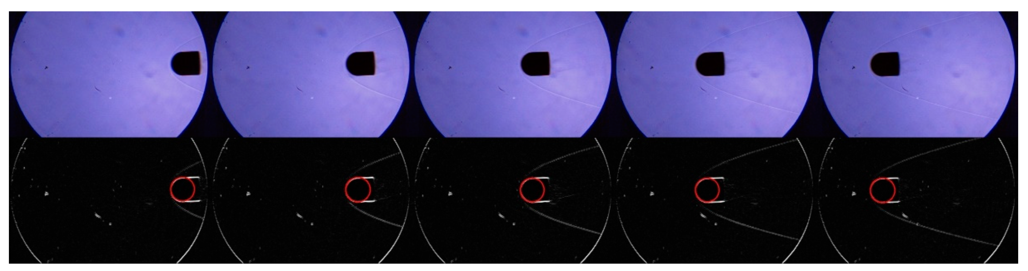
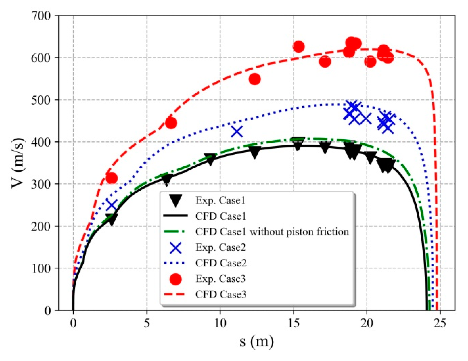
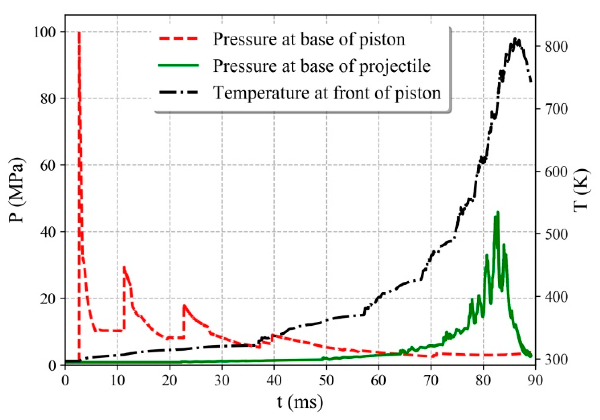
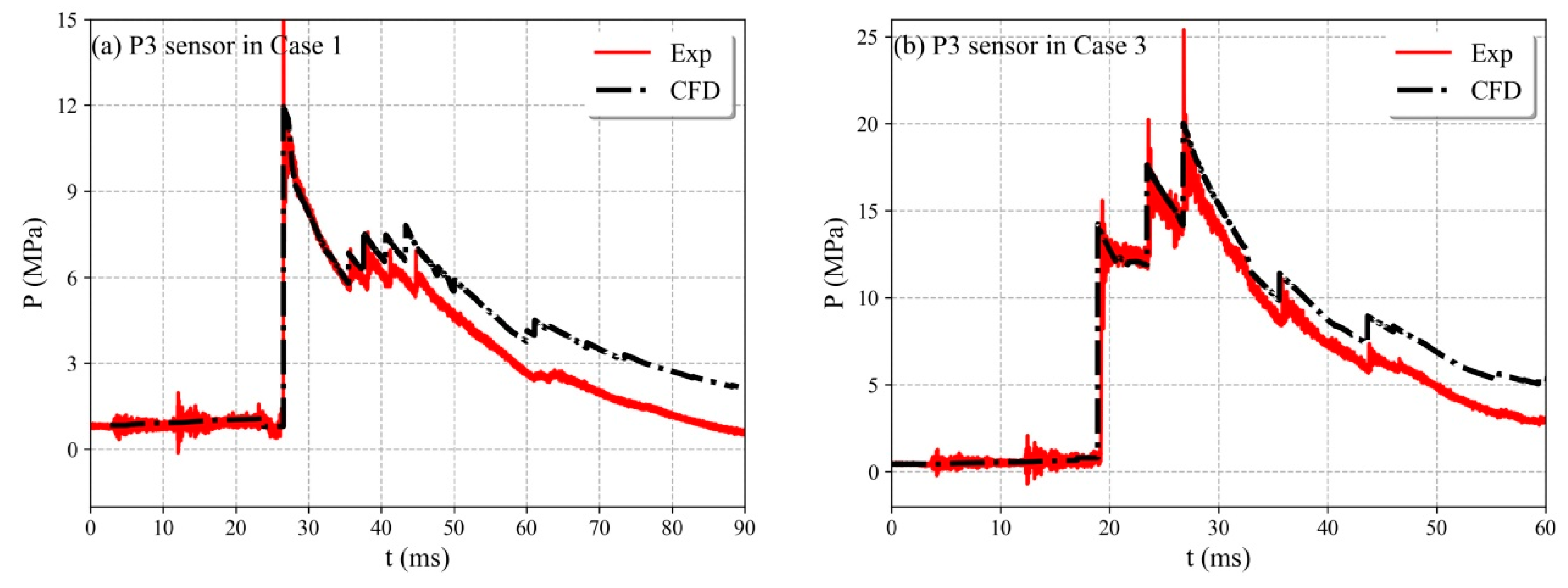
4.2. Comparison of Simulation and Experimental Results

Figure 7 shows the piston speed versus the travel distances for the three cases, including the experimental and numerical results. The numerical results agree well with the corresponding experimental ones using the above models; and the differences are within ± 10%, which is acceptable for the two-stage gas gun simulation. The numerical result without the piston-wall friction term for Case 1 is also shown in Figure 7. The results that include the piston friction are only 5% lower than those that do not include the piston friction. Thus, the values of Lf and ∆r (defined in Section 3.3) have only small influences on the piston speed in the simulation.
Unlike a gas gun that is driven by high-pressure gases, which results in smooth changes in the piston speed, the detonation-drive gas gun produces fluctuations in the piston speed, as shown in Figure 7. This result is attributed to the complex interior ballistic process in the gas gun driven by detonation. The direct ignition at the upstream end in the detonation tube leads to a stable detonation wave traveling downstream. The detonation wave reflects from the base of the piston, generating a shock wave, and the motion of the piston generates compression waves. This shock wave then reflects several times between the end of the detonation tube and the base of the piston, which subjects the piston to a series of impulse loads, leading to fluctuations in the piston speed. The pressure at the base of the piston and projectile are shown in Figure 8; fluctuations also exist due to the shock wave reflections. The fluctuations are extensive in the initial stage and gradually weakened over time. However, it should be noted that the pressure at the base of the projectile was actually the pressure on diaphragm II before 82.8 ms. Since the projectile was placed close to diaphragm II, we use this pressure to monitor the pressure on diaphragm II or the pressure histories at the base of the projectile at the same time.
In the simulation of Case 1, diaphragm II ruptures at 82.8 ms, and the projectile exits the launch tube at 88.2 ms; the corresponding times are 56.7 ms and 59.8 ms for Case 3, respectively. Thus, the pressure histories from 0 to 90 ms for Case 1 and 0 to 60 ms for Case 3 are chosen in the present discussion. Figure 9 and Figure 10 show the experimentally measured and computed pressure histories at the monitoring points in the pump tube. In Figure 9, the pressure histories of P3 are displayed for Case 1 and Case 3. The first significant pressure increase was due to the passing of the piston or the arrival of the high-pressure detonation gas. The pressure changes following the increase indicate the complicated gas-dynamic processes between the piston base and the left wall of the facility. The simulation results show a similar trend as the experimental results. Additionally, the pressure value of the experiment agrees well with that of the simulation in the initial stage. However, the differences increase over time. It is believed that this result is attributable to a transducer problem rather than a code problem and is related to the influence of the high-temperature gas on the piezoelectric pressure transducers, which are supposed to operate at a temperature of 353 K. However, the temperature of the detonation gas is higher than 3000 K, and the temperature of the light gas also increases as it is compressed, as shown in Figure 8. The temperature of the light gas at the front of the piston exceeds 400 K at 60 ms for Case 1, and the maximum temperature exceeds 800 K. The temperatures are even higher for Case 2 and Case 3 because of higher piston speeds. Thus, the pressure transducer is exposed to high-temperature gases. Pressure differences occur and increase after a specific time. This phenomenon is also observed in Figure 10. More suitable high-temperature pressure sensors will be used in the future to validate the numerical results.
The pressure changes due to the geometric variation in the longitudinal direction of the piston (see Figure 3b) are difficult to simulate. Thus, the pressure between the period of piston front and piston rear in the simulation is set equal to the initial pressure in the pump tube, i.e., 0.8 MPa for Case 1, as shown in Figure 10a between the time moment of 68.8 ms to 70.7 ms. However, they do not participate in the calculation and have no influence to the simulated results. Additionally, it can be found that there are larger discrepancy between CFD and Exp for P6 and P9 sensor after the passing of the piston. The reason may attribute to the inaccurate estimation of the energy exchange between the high temperature detonation gas (exceeds 3000 K) and the tube wall. This influence may go greater as time increases.
The launch tube has a relatively small diameter, and it would be complicated to measure the projectile velocity along the tube wall. Thus, only the muzzle velocity value is measured in the experiments; the results for Case 1 and 2 are listed in Table 1. However, in the simulation, we can obtain the projectile speed versus the projectile travel distance, as shown in Figure 11. The friction between the projectile and the wall is considered to be similar to that between the piston and the wall, as described in Section 3.3. The simulated projectile velocities at the exit of the launch tube are 2481 m/s, 2260 m/s, and 4854 m/s for Case 1, Case 2, and Case 3, respectively. The measured projectile velocities (Table 1) are 2481 m/s and 2260 m/s for Case 1 and Case 2, respectively. These values are about 14% lower than the numerical results. One reason for the difference is the rough estimate of the rupture pressure of diaphragm II. Scored diaphragms are used, and their rupture pressures are challenging to obtain experimentally under such a high pressure. The influence of the high-temperature light gas on the rupture pressure is also difficult to determine. Thus, only a semi-empirical formula is used to estimate the rupture pressure. The rupture pressure is 45 MPa for Case 1 and Case 2 and 75 MPa for Case 3. The influence of the rupture pressure on the projectile velocity is shown in Figure 12. Rupture pressures of 30 MPa, 45 MPa, and 75 MPa are considered for diaphragm II, and the other parameters are the same as in Case 1. A higher rupture pressure delays the rupture of diaphragm II, resulting in higher gas compression of the light gas; hence, the light gas provides a higher driving capability. The muzzle projectile velocities are 2553 m/s, 2601 m/s, and 2742 m/s for the three cases, respectively. In a future study, we will use simulations to model the rupture process of the diaphragm and improve the present method.
Other reasons for the differences may be the roughness of the launch tube wall, the melting of the landing surface of the projective, improper data on the high strain rate deflection and yielding behavior of the projectile material, and that the viscous dissipation term between the high temperature light gas and tube wall are not completely accurate. However, the present simulation is acceptable for the identification and assessment of new operating parameters of the test conditions.

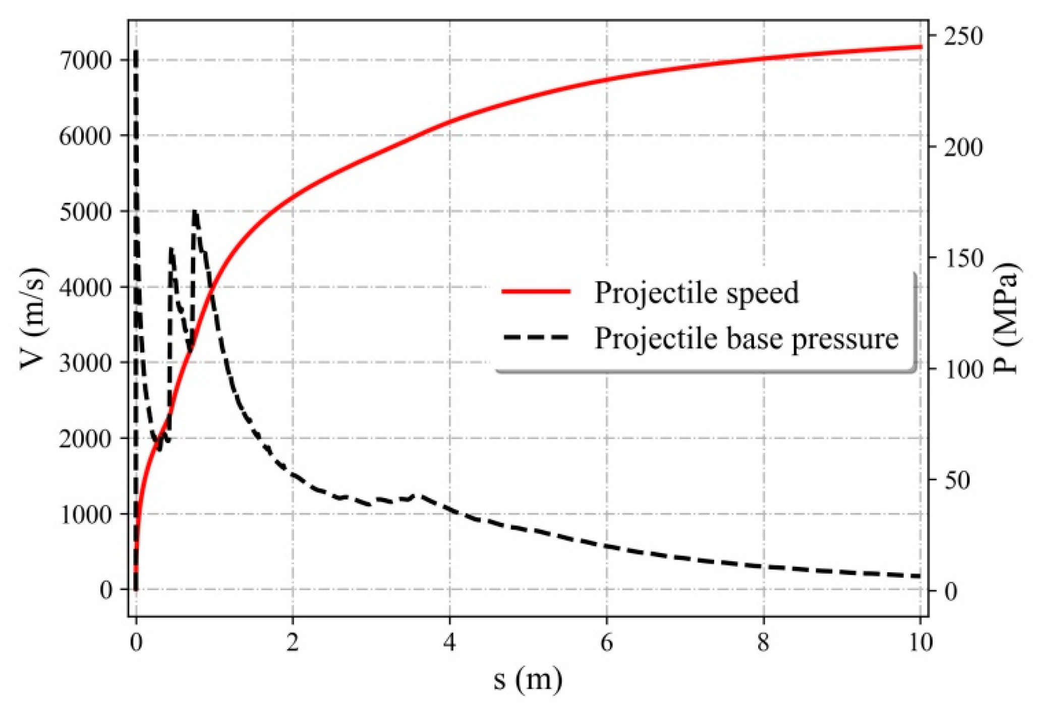
4.3. Effects of the Pump Tube Pressure

For any particular gun with a fixed geometry, the operating parameters or loading condition that can be adjusted to achieve the desired velocity include the initial gas conditions in the pump tube, the piston mass, the rupture pressure of diaphragm II, and the projectile mass. However, it is desirable to minimize the maximum base pressures to obtain the most uniform base pressure history and maintain gas reservoir pressures that are within the strength capabilities of the gun. Generally, the initial pressure of the pump tube and detonation tube is the easiest parameter to adjust.
The influence of the initial pump tube pressure on the gas gun was investigated; the operating conditions for Case 4 are listed in Table 2. Figure 13 shows the piston and projectile speed as a function of the pump tube pressure. Since the pump tube pressure tends to limit the acceleration of the piston, the piston speed decreases as the pump tube pressure increases at different detonation pressures. However, the pump tube pressure has little influence on the maximum piston speed, and the detonation pressure is the dominant influence. The projectile velocity has an optimal value at different pump tube pressures. For example, at a detonation pressure of 3.0 MPa, the maximum projectile speed occurs at a pressure of 0.4 MPa. The projectile base pressure in the launch tube is presented in Figure 14. When the initial pump tube pressure is lower than 0.4 MPa, the projectile has a relatively high base pressure of more than 130 MPa, indicating high acceleration in the early stages. However, the density decreases rapidly due to the lower initial pressure after the projectile has traveled about 2 m in the launch tube, leading to a significant decrease in the base pressure of the projectile. When the initial pump tube pressure is higher than 0.4 MPa, the peaks of the pressure of the projectile are much lower, and the curves are smooth due to stable acceleration. For the other different detonation pressures, the maximum projectile speed occurs at different initial pump tube pressure. At a detonation pressure of 1.5 MPa, an optimal projectile speed is not observed at the pump tube pressure range of 0.2 to 1.2 MPa.
We estimated the maximum capabilities of the gaseous detonation-driven two-stage light-gas gun. We increased the rupture pressure of diaphragm II to 150 MPa and maintained the maximum piston velocity at less than 900 m/s to protect the high-pressure section of the barrel. An appropriate set of calculation parameters was chosen (Case 5). The projectile velocity and base pressure are shown in Figure 15. The projectile muzzle velocity is more than 7100 m/s, and the maximum base pressure is close to 250 MPa, which is lower than the strength of the metal. Therefore, if we further optimize the launch parameters, the muzzle velocity of the projectile with a mass of less than 20 g can reach 6–8 km/s.

5. Conclusions

Due to strict controls of gunpowder, the use of traditional two-stage light-gas guns has limitations. Therefore, it is necessary to develop a new driving method for two-stage light-gas guns in laboratory conditions. In the present study, a two-stage light-gas gun driven by gaseous-detonation was developed, and its performance was evaluated. An accurate and rapid computational method was also implemented to simulate the flow or piston/projectile movement in the light-gas gun. The proposed method explains the wave propagation process in the tubes and provides a detailed piston/projectile trajectory. This type of model is required because different tests are conducted frequently in experimental facilities, and simulations are needed. The proposed quasi-one-dimensional model provides accurate simulation results of the internal ballistic process of the light-gas gun.
The results under different test conditions show that the quasi-one-dimensional modeling of the two-stage light-gas gun driven by gaseous detonation provides reliable performance data. The maximum muzzle velocity of the current design is 6–8 km/s. Although this study has focused on the DBR30 gas gun, the modeling is generic and may be applied to other facilities.

Author Contributions

Conceptualization, Q.W.; Data curation, J.S.; Formal analysis, J.L. (Jiwei Li) and J.L. (Jinping Li); Funding acquisition, K.Z.; Methodology, B.W. and W.Z.; Writing—original draft, W.T. All authors have read and agreed to the published version of the manuscript.

Funding

This research was funded by the Strategic Priority Research Program of the Chinese Academy of Sciences (Grant No. XDB22040303) and the National Natural Science Foundation of China (Grant No. 1197021407).

Acknowledgments

We thank Xijun Shi for his support in the experimental work.

Conflicts of Interest

The authors declare no conflict of interest.

References

  1. Seiler, F.; Igra, O. (Eds.) Hypervelocity Launchers; Springer: Berlin, Germany, 2016; Volume 10, pp. 23–52. [Google Scholar]
  2. Crozier, W.D.; Hume, W. High-Velocity, Light-Gas Gun. J. Appl. Phys. 1957, 28, 892–894. [Google Scholar] [CrossRef]
  3. Canning, T.N.; Seiff, A.; James, C.S. Ballistic-Range Technology; AGARD: Neuilly sur Seine, France, 1970. [Google Scholar]
  4. Lukasiewicz, J. Experimental Methods of Hypersonics; M. Dekker: New York, NY, USA, 1973; Volume 3. [Google Scholar]
  5. Reda, D.C. Correlation of nosetip boundary-layer transition data measured in ballistics-range experiments. AIAA J. 1981, 19, 329–339. [Google Scholar] [CrossRef]
  6. Strawa, A.W.; Chapman, G.T.; Canning, T.N.; Arnold, J.O. Ballistic range and aerothermodynamic testing. J. Aircr. 1991, 28, 443–449. [Google Scholar] [CrossRef]
  7. Chapman, G. The ballistic range—Its role and future in aerothermodynamic testing. In Proceedings of the 17th Aerospace Ground Testing Conference, Nashville, TN, USA, 6–8 July 1992; American Institute of Aeronautics and Astronautics: Reston, VA, USA, 1992; p. 3996. [Google Scholar]
  8. Marren, D.; Lu, F. Advanced Hypersonic Test Facilities; American Institute of Aeronautics and Astronautics: Reston, VA, USA, 2002; p. 138. [Google Scholar]
  9. Junde, L. An analysis of launching parameters for a two stage light gas gun not driven by powder. Explos. Shock Waves 1995, 3, 229–240. [Google Scholar]
  10. Carver, D.; Campbell, L.L.; Roebuck, B. Large-scale, hypervelocity, high-fidelity interceptor lethality development in AEDC’s range G. Int. J. Impact Eng. 2008, 35, 1459–1464. [Google Scholar] [CrossRef] [Green Version]
  11. Charters, A.C. Development of the high-velocity gas-dynamics gun. Int. J. Impact Eng. 1987, 5, 181–203. [Google Scholar] [CrossRef]
  12. Bogdanoff, D.W.; Miller, R.J. New Higher-Order Godunov Code for Modelling Performance of Two-Stage Light Gas Guns; NASA’s Ames Research Center: Mountain View, CA, USA, 1995. [Google Scholar]
  13. Liang, S.C.; Huang, J.; Li, Y.; Jian, H.X. Numerical research on interior ballistics of two-stage light-gas gun. Phys. Gases 2012, 7, 80–84. [Google Scholar]
  14. Kruczynski, D.; Massey, D.; Milligan, R.; Vigil, E.; Landers, B.; Meneguzzi, M. Combustion Light Gas Gun Technology Demonstration; UTRON Inc.: Manassas, VA, USA, 2007. [Google Scholar]
  15. Dong, S.; Meng, C.; Xiao, Y.; Mo, J.; Zhang, M.; Wang, X.; Shi, S. Preliminary Study of Two-Stage Light Gas Gun Using Reactive Gas as Driving Energy. Chin. J. High. Press. Phys. 2017, 31, 182–186. [Google Scholar]
  16. Deng, F.; Zhang, X.Y. Simulation of Hydrogen-Oxygen Combustion of Combustion Light Gas Gun Using Detailed Chemical Kinetics Model. Acta Armamentarii 2014, 19, 415–420. [Google Scholar]
  17. Deng, F.; Zhang, X.Y.; Liu, N. Influences of ignition process and initial conditions on interior ballistic characteristics of combustion light gas gun. Explos. Shock Waves 2013, 33, 551–555. [Google Scholar]
  18. Deng, F.; Liu, N.; Zhang, X.Y. Analysis on influence of propellant component on interior ballistics of combustion light gas gun. J. Ballist. 2012, 24, 90–93. [Google Scholar]
  19. Bird, G.A. A Note on Combustion Driven Tubes; Royal Aircraft Establishment: Farnborough, UK, 1957; Volume 146. [Google Scholar]
  20. Lu, F.K.; Wilson, D.R.; Bakos, R.J.; Erdos, J.I. Recent Advances in Detonation Techniques for High-Enthalpy Facilities. AIAA J. 2000, 38, 1676–1684. [Google Scholar] [CrossRef] [Green Version]
  21. Presles, H.N.; Bauer, P. Detonation products gun. Rev. Sci. Instrum. 1983, 54, 1511–1512. [Google Scholar] [CrossRef]
  22. Batchelor, P.L. Development of a gaseous detonation driven hypervelocity launcher. Master’s Thesis, University McGill, Montreal, QC, Canada, 2010. [Google Scholar]
  23. Li, J.P.; Chen, H.; Zhang, S.Z.; Zhang, X.Y.; Yu, H.R. A gasdynamic gun driven by gaseous detonation. Rev. Sci. Instrum. 2016, 87, 15112. [Google Scholar] [CrossRef] [PubMed] [Green Version]
  24. Sichel, M.; Tonello, N.A.; Oran, E.S.; Jones, D.A. A two–step kinetics model for numerical simulation of explosions and detonations in H2-O2 mixtures. Proc. Math. Phys. Eng. Sci. 2002, 458, 49–82. [Google Scholar] [CrossRef]
  25. Jiang, Z.L. Dispersion conditions for non-oscillatory shock capturing schemes and its applications. Comput. Fluid Dyn. J. 1995, 2, 137–150. [Google Scholar]
  26. Li, J.P.; Jiang, Z.L.; Chen, H.; Feng, H.; Yu, H.R. Numerical study on backward-forward double-detonation driver for high enthalpy shock tubes. Chin. J. Theor. Appl. Mech. 2007, 3, 343–349. [Google Scholar]
  27. Jacobs, P.A. Quasi-one-dimensional modeling of a free-piston shock tunnel. AIAA J. 1994, 32, 137–145. [Google Scholar] [CrossRef]
  28. Chue, R.S.M.; Tsai, C.Y.; Bakos, R.J. Driver gas contaminationin a detonation-driven reflected-shock tunnel. Shock Waves 2003, 13, 367–380. [Google Scholar] [CrossRef]
  29. Grossir, G.; Ilich, Z.; Chazot, O. Modeling of the VKI Longshot Gun Tunnel Compression Process Using a Quasi-1D Approach. In Proceedings of the 33rd AIAA Aerodynamic Measurement Technology and Ground Testing Conference, Denver, CO, USA, 5–9 June 2017; American Institute of Aeronautics and Astronautics: Reston, VA, USA, 2017; p. 3985. [Google Scholar]
  30. Ebnesajjad, S. Expanded PTFE Applications Handbook: Technology, Manufacturing and Applications; William Andrew: Norwich, NY, USA, 2016; pp. 163–170. [Google Scholar]
Figure 1. Schematic diagram of the two-stage light gas gun (not to scale, units in mm).
Applsci 10 04383 g001
Figure 2. Schematic diagram of the piston (not to scale, units in mm).
Applsci 10 04383 g002
Figure 3. Pressure periods in the pump tube during the piston movement passing through the sensor. (a) P3 sensor; (b) P8 sensor.
Applsci 10 04383 g003
Figure 4. Results of high-speed photography with a time interval of 13.3 μs; the projectile has a diameter of 30 mm and the velocity is 2481 m/s; the pressure in the target chamber is 5000 Pa. The optical window was 3320 mm away from the muzzle exit.
Applsci 10 04383 g004
Figure 5. Changes in the radius of the piston at different positions versus time after removing it from the freezer.
Applsci 10 04383 g005
Figure 6. Speed and pressure at the base of the piston for Case 1 and three grid resolutions.
Applsci 10 04383 g006
Figure 7. Piston speed versus piston travel distance.
Applsci 10 04383 g007
Figure 8. Simulated pressure and temperature at the base and front of the projectile or piston for Case 1.
Applsci 10 04383 g008
Figure 9. Pressure histories of the P3 sensor. (a) Case 1; (b) Case 3.
Applsci 10 04383 g009
Figure 10. Pressure histories for Case 1. (a) P6 sensor; (b) P9 sensor.
Applsci 10 04383 g010
Figure 11. Simulated projectile velocity versus projectile travel distance.
Applsci 10 04383 g011
Figure 12. Simulated projectile velocities versus projectile travel distance for different rupture pressure values of diaphragm II.
Applsci 10 04383 g012
Figure 13. Simulated results at different detonation pressures. (a) maximum piston speed versus the initial pump pressure; (b) muzzle projectile speed versus the initial pump pressure.
Applsci 10 04383 g013
Figure 14. Simulated projectile base pressure versus the projectile travel distance for different pump tube pressure at a detonation pressure of 3.0 MPa.
Applsci 10 04383 g014
Figure 15. Projectile speed and base pressure for Case 5.
Applsci 10 04383 g015
Table 1. Operating conditions in the experiments and simulation.
Case 123
Detonation tubeMixing molar ratio, H2:O23:1
Pressure (MPa)1.52.02.7
Pump tubeGasH2
Pressure (MPa)0.80.80.45
Piston mass (kg)10.44
Rupture pressure (MPa)454575
Launch tubeProjectile mass (g)1910031
Exp.Projectile velocity (m/s)24812260
CFD 283926014854
Relative error (%)14.415.1
Table 2. Operating conditions in the simulation of Case 4 and Case 5.
Case 45
Detonation tubeMixing molar ratio, H2:O23:1
Pressure (MPa)1.5, 2.0, 3.0, 5.05.0
Pump tubeGasH2
Pressure (MPa)0.2, 0.4, 0.6, 0.8, 1, 1.20.6
Piston mass (kg)1012.5
Rupture pressure (MPa)45150
Launch tubeProjectile mass (g)1910

