Abstract
Swing usually occurs in the maneuver process of a tethered combination, which is constituted of a platform, a tether and a target (i.e., space debris) for capture. Therefore, a dynamical model of the space tethered combination was established, based on the maneuver of the mission platform in a short time. The conditions for the three swing formations of the tethered combination were obtained according to the analysis of the dynamical model. In order to solve the swing problem, anti-swing control strategies, based on linear feedback control, approximate linearization control and variable structure control, were proposed, respectively. Furthermore, simulation results verified the correctness and effectiveness of the above strategies. To test the validity of the control strategies, a ground experiment setup was built according to the similarity of dynamics. The experimental results show that linear feedback control and approximate linearization control can suppress the in-plane and out-of-plane swing of the combination rapidly.
1. Introduction
With the increase of human aerospace activities, space debris problems become more and more pronounced. The space debris environment is seriously threatening the development of aerospace projects [1]. Especially in geostationary earth orbit (GEO), it has important military value and a strategic position in communication, navigation, meteorology and investigation. However, these orbital resources are quite limited. There is no extra energy to deorbit the space debris from GEO, so the space debris, which will be the cataloguing targets, increases steadily, with a rate of 30 per year. The severity and frequency of the disintegration events will increase with the mass and cross section area of the orbiting objects. Based on this situation, the active removal technology of non-cooperative targets, such as space debris, has become one of the hotspots in the field of space research [2,3,4]. In order to meet the requirements of non-cooperative target capture tasks, the concept of flexible capture has gradually entered human vision, which covers the target with flexible structures (e.g., net, cloth), and forms a reliable combination with the mission spacecraft through a flexible tether.
In recent years, many research teams have carried out a number of projects on flexible capture. The typical space flexible capture projects include the ROGER (Robotic Geostationary Orbit Restorer) of the ESA (European Space Agency) [5], the electric debris removal device EDDE (Electro Dynamic Debris Eliminator) of the American Star Company [6,7], the asteroid capture program ARM (Asteroid Retrieval Mission) of NASA [8,9], the Furoshiki satellite project of Japan [10,11] and so on. However, whatever the flexible capture system, in the maneuver process for the space tethered combination after target capture, the physical phenomena of collision, swing, tumbling and recombination between the flexible capture system and the targets can easily occur in a very weak gravity field, which will affect the measurement, and control and communication with the capturing platform. Hence, the above-mentioned problems must be analyzed and controlled.
There are some discussions on the maneuver dynamics and control of the space tethered combination, and the feedback tension control [12,13], optimal control [14], predictive control [15] input-shaping control [16,17] that are applied to the space tethered combination. In recent years, some research on the swing analysis and control of the space tethered combination has been conducted. Aslanov studied the dynamics of deorbiting large space debris by means of a tethered space-tug under the action of a space tug thruster [18,19]. Liu developed a sophisticated mathematical model, taking into account the system’s orbital motion, the relative motion of two spacecraft and spacecraft attitude motion, and the possible risks, such as tether slack, spacecraft collision, tether rupture, tether-tug intertwist and the destabilizing of the tug’s attitude [20]. Wang established the general nonlinear dynamics of the tethered combination system in the post-capture phase with the consideration of the attitudes of two spacecrafts and the quadratic nonlinear elasticity of the tether, and analyzed the inter resonance phenomenon of a simplified model [21]. Sun analyzed the librational and vibrational characteristics of the tethered system, and designed a sliding mode controller in the orbital plane [22,23]. Liu designed a tether tension control law for use during orbital transfer via the small-gain theorem, which can suppress the swing of the space tethered combination [24]. However, the out-of-plane motion was not taken into account, and the validity of the swing control strategies were not tested in the above research.
In this paper, we focus on the analysis and controller design of the swing. The purpose of this paper is to find some simple methods that are easy to implement in engineering. Firstly, a dynamical model of the space tethered combination, based on the maneuver of the mission platform, was established. Additionally, three formations of the swing of the tethered combination were analyzed according to the dynamical model. Secondly, in order to solve the swing problem, the anti-swing control strategies, such as linear feedback control, approximate linearization control and variable structure control, were proposed. Lastly, the ground experiment setup was built to test the control strategies.
2. Swing Dynamics and Analysis
2.1. Dynamical Model
The schematic diagram of the space tethered combination in the maneuver process after target capture is shown in Figure 1. The mass center of mission platform O0 is equivalent to the towing point, which can move freely. The mass of the target is m and the coordinate of the mass center is O1. The target is connected to the mission platform by a tether. The tether’s length is l, and the tension force of the tether is FT. The orbital reference frame O0XYZ is established, with its origin attached to the towing point O0, its X-axis pointing to the Earth’s center Oe, its Y-axis perpendicular to the x-axis in the orbital plane and contrary to the motion direction, and its Z-axis along the positive norm of the orbital plane. It is considered that the orbit motion of the mission platform is linear, along with the Z-axis when it runs on high orbit in a short time. Hence, the Earth-centered inertial reference frame Oexyz is established, with its origin attached to the Earth’s center, and the x-axis, y-axis and z-axis parallel to X-axis, Y-axis and Z-axis, respectively. The angles θ and φ are named ‘in-plane’ and ‘out-of-plane’, relative to the frame O0XYZ. For convenience of analysis, the spherical coordinate frame O0-αβl is defined. Let α and β be the apex angle and azimuth angle of the spherical coordinate frame. It is assumed that the mission platform is completely controllable by thrust force, and the acceleration components provided by the thrust force are ax, ay, az, respectively. The z acceleration component az is constant, in order to realize the maneuver of the tethered combination, and ax, ay are controllable in order to realize the in-plane and out-of-plane swing control of the tethered combination.
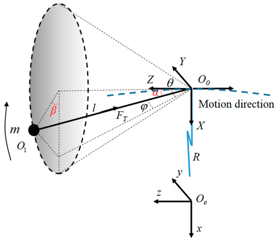
Figure 1.
Swing model of the space towing tethered combination.
The following assumptions are made:
- (1)
- The mission platform is completely controllable, so the influences of its mass and attitude motion are neglected.
- (2)
- The target is treated as a mass point, regardless of its attitude motion.
- (3)
- The tether is taut and straight at all times, regardless of its mass and elasticity.
- (4)
- There are no other external forces affecting the combination, such as atmospheric drag, solar light pressure and lunisolar perturbation, etc.
By a straightforward application of Lagrange’s equations, with the generalized coordinate vector q = {θ,φ,l}T∈Rn, substituting ax = into equations, the swinging dynamical model of the space tethered combination can be obtained as follows:
2.2. Swing Analysis
According to Equation (1), the in-plane swing angle θ and the out-of-plane swing angle φ are coupled with each other, and the motion of the space tethered combination in the maneuver process is a two-dimensional swing, generally. Furthermore, as shown in Figure 1, the target motion relative to O0 is distributed on the sphere, with O0 as the center and l as the radius, which is called ‘spherical swing’. This is the first swing form of the tethered combination, which is also the most common case. When , it can be obtained that , which means that the state can be kept infinitely. Therefore, it can be seen that the motion of the space tethered combination is in-plane swing if there is no out-of-plane swing disturbance at the initial time. This is the second swing form of the tethered combination. The target motion will evolve into a circular motion when the initial tangential velocity of the target satisfies certain conditions. This is the third swing form of the tethered combination, called conical swing, named according to the cone shape of the tether’s motion trajectory, which is another special case of spherical swing. In the conical swing form, the apex angle α is constant. The dynamic model of the space towing tethered combination is expressed in the spherical coordinate as follows:
When the tether length l is constant, the problem can be simplified as follows:
The notation α0 is the initial apex angle, l0 is the initial tether length and v0 is the initial tangential velocity during the conical swing. Hence, the apex angle is constant with the value α0, and the change rate of the apex angle and its second derivative yield .
By the integration of Equation (3), the angular velocity of the azimuth angle is obtained as follows:
Substituting Equation (4) into Equation (3), it can be obtained as follows:
Thus, the initial tangential velocity can be obtained:
It can be seen that the formation condition of the conical swing motion is related to the initial value of apex angle α0 and the initial tangential velocity v0 from Equation (6).
According to Equations (3) and (6), the swing of the space tethered combination was simulated. The system parameters were set up as follows: the initial tether length l0 = 3 m, the initial internal swing angle α0 = 30° = 0.52 rad, the acceleration az = −5 m/s2 and v0 = 2.08 m/s can be obtained by calculation from Equation (3). The simulation result of the target trajectory mapped to the XY-plane is shown in Figure 2a, which is a circle of 1.5 m radius. For comparison, the initial velocity of the target was set to v2 = 0.83 m/s; the simulation result of the target trajectory mapped to the XY-plane is shown in Figure 2b, which is composed of a series of precessional ellipses.
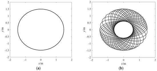
Figure 2.
The trajectory of the target mapped to the XY-plane. (a) Conical swing; (b) Elliptical swing.
3. Swing Control and Simulation Study
3.1. Feedback Linearization Control
The essence of feedback linearization control is the state of a closed-loop feedback. In the control strategy design process, the actual control law is obtained indirectly from the virtual control law, and the virtual control law can be obtained directly by the state differential equation constructed. The desired value of the in-plane swing angle and out-of-plane swing angle were set to θd = φd = 0; the stabilizing control strategy of the space tethered combination has been designed as follows.
Based on Equation (1), the virtual control law of the in-plane and out-of-plane swing angle is obtained:
where uθ is the virtual control of θ, uφ is the virtual control of φ and kij (i = 1,2; j = θ,φ) are the control parameters. This can be written as
where eθ is the in-plane swing angle error and eφ is the out-of-plane swing angle error.
The control parameters kij > 0 mean that the coefficients of the characteristic equation for the typical second-order system in Equation (8) are positive. Thus, the feedback linearization control system is stable according to the Routh criterion, and both the in-plane swing angle θ and out-of-plane swing angle φ are finally stable at the expected value θd.
According to Equations (2) and (7), the angle control law of the towing point (uαx1, uαy2) is obtained:
where ux and uy are the anti-swing control inputs of the towing point in the x direction and y direction, respectively.
Due to the integral relationship between the acceleration, velocity and displacement, the acceleration and deceleration processes will mean that the velocity and displacement of the towing point are stable at a certain constant value over time. The PID controller was used to realize the velocity and displacement control of the towing point. Based on the feedback linearization control, a triple closed-loop anti-swing control strategy that includes angle closed-loop, velocity closed-loop and displacement closed-loop was designed, as shown in Figure 3.
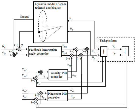
Figure 3.
Schematic diagram of the anti-swing control strategy, based on feedback linearization control.
Angle closed-loop: The swing angle error serves as the angle’s closed-loop input, and the control output (uαx1, uαy2) is obtained from the feedback linearization controller defined in Equation (9). The purpose of this loop is to stabilize the in-plane and out-of-plane swing angle.
Velocity closed-loop: The velocity error serves as the closed-loop input, and the feedback velocity value () is obtained from the integral of the towing point acceleration () = (ux,uy). The feedback velocity value is considered to be approximately equal to the actual measured velocity value in the simulation.
Displace closed-loop: The displacement error serves as the displacement closed-loop input, and the feedback displacement value (x, y) is obtained from the integral of the towing point velocity value (). The feedback displacement value is considered to be approximately equal to the actual measured displacement value in the simulation.
The complex control law (u’x, u’y) is obtained from the interaction of the angle closed-loop law (uαx, uαy), the velocity closed-loop law (uvx, uvy) and the displacement closed-loop law (usx, usy), which can control the swing angles of the target, and the velocity and displacement of the towing point. Assume that the initial state of the towing point is () = (x0, y0) = (0, 0), and the velocity is set at () = (xd, yd) = (0, 0). The control law (uvx, uvy) and the displacement control law (usx, usy) of the towing point are obtained by PID controller:
where ∆vx, and ∆vy are the velocity component errors of the towing point, and ∆x and ∆y are the displacement component errors of the towing point.
According to Equations (9) and (10), the complex control law (u’x, u’y) can be obtained:
The anti-swing control law expressed in Equation (11) is applied to the dynamical model of the space tethered combination in the maneuver process expressed in Equation (1). The tether length l is constant, and the case of short tether is considered. The physical parameters and initial conditions used in simulation are listed in Table 1.

Table 1.
Simulation initial parameters.
First, the case without control was studied as a comparison. With the initial parameters given in Table 1, the simulation results are shown in Figure 4. The trajectory of the target mapped to the XY-plane is composed of a series of precessional ellipses, as shown in Figure 4a. The precession angle of the elliptical trajectory is related to the major axis and minor axis of the ellipse, as follows:
where ∆θ is the angle between the major axes of adjacent elliptical trajectories, and a and b are respectively the major axis length and minor axis length of the elliptical trajectory. The time history of the in-plane swing angle and out-of-plane swing angle are shown in Figure 4b. When the swing elimination control is not applied, the response of the in-plane and out-of-plane swing is varied amplitude periodical vibration, and there is a phase difference between them.
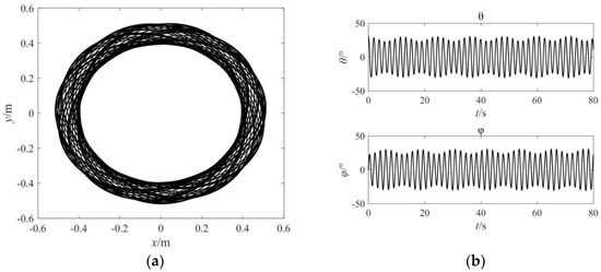
Figure 4.
Simulation results without control. (a) The trajectory of the target mapped to the XY-plane; (b) The response of in-plane and out-plane swing angle.
Under the same initial conditions, the anti-swing control of the space towing tethered combination was carried out. The expected velocity demand of the towing point was set to () = (0, 0) and the displacement of the towing point was set to (xd, yd) = (0, 0); the simulation results with triple closed-loop control are shown in Figure 5. It can be seen that the control inputs u range between −1 m/s2 and 1 m/s2. The towing point returns to the origin with zero speed after control, which can be seen from the velocity response and the displacement response. The tether is always taut with nonnegative tension, meaning that the anti-swing control is physically achievable. The in-plane swing angle and out-of-plane swing angle decay dramatically to 0° under the feedback linearization control strategy. For the short period swing in the case with the short tether, the swing elimination control Equation (12) can quickly stabilize the internal and external swing angle. This indicates that the feedback linearization swing control is effective, and can suppress the swing of the space towing tethered combination.
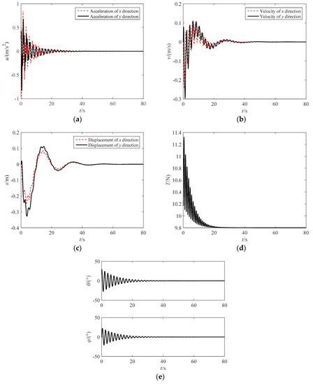
Figure 5.
Simulation results with feedback linearization control. (a) Acceleration of the towing point; (b) Velocity of the towing point; (c) Displacement of the towing point; (d) Tether tension; (e) In-plane and out-of-plane swing angle of the target.
3.2. Approximate Linearization Control
The nonlinear system can be degenerated into a second order gauge system by the linearization of the nonlinear terms. Based on the analysis of the second-order gauge system, the damping ratio and the frequency of the free oscillation were easily calculated, and a good transient response of the system was obtained. Compared with the exact linearization based on Li derivative analysis [25], the parameters of a nonlinear system model were required, and the Li derivative condition was satisfied. The approximate linearization control is widely used to deal with a class of state stability problems. In this section, an approximate linear control law is designed for the space towing tethered combination model, and the control effect is compared with the feedback linearization control in the previous section.
Approximate linearization ignores the higher order terms by Taylor approximation, and achieves decoupling. The trigonometric function can be expanded into a Taylor series near the stable position:
Ignoring the higher order items and truncating the first order item, the system’s dynamical equation is obtained after the approximate linearization according to the Equation (1):
where θ, φ, the angle less than 10 degrees can be satisfied.
Equation (14) is a typical specification system of the second-order, which can control swing based on a PD controller. The angle control law of the towing point (uαx2, uαy2) is obtained:
Substituting Equation (15) into Equation (14), we obtain:
Because of the parameters kij > 0, g > 0, l > 0, the coefficients of the characteristic equation for the typical second-order system in Equation (16) are positive. Thus, the approximate linearization control system is stable according to the Routh criterion.
In the same way, the compound control inputs (u′x, u′y) are obtained by the triple closed-loop control:
where kij(i = p, d;j = 1,2) are control parameters.
Setting control parameters as kp1 = 1, kd1 = 1, kp2 = 1, kd2 = 1, the simulation results with approximate linearization control are shown in Figure 6. Under the action of approximate linear control, the swing angle can finally be stable, and the velocity and displacement reach the demand value rapidly. The control process is closely related to parameters kij. Thus, the parameters’ optimization can be designed using the intelligent PID or parameter self-tuning PID control in the following research.
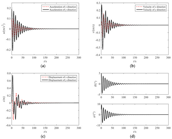
Figure 6.
Simulation results with approximate linearization control. (a) Acceleration of the towing point; (b) Velocity of the towing point; (c) Displacement of the towing point; (d) In-plane and out-of-plane swing angle of the target.
3.3. Variable Structure Control
Variable structure control (VSC) is a typical control strategy used in nonlinear systems for its various attractive features, such as its rapid response, good transient performance and robustness with respect to uncertainties and external disturbance.
The theoretical idea of the variable structure control is to construct the state hyperplane, such as by constructing the s = cTx about the state variable set x and designing the state approach law, which satisfies the derivative negative definite of the Lyapunov function V = 1/2 s2 and stabilizes the state variable set.
By applying the VSC to control the swing of the space towing tethered combination, the sliding mode control law is designed as two subsystems; and . As a usual method in VSC theory, the linear switching function is chosen as follows: and , and the approach law is , where λ, η are parameters of the sliding mode approach law.
Assuming that (ax, ay) = (uαx3, uαy3) and the tether length is a constant, the dynamics of the space towing tethered combination can be recast into the following state-space form:
where
, , , , .
The angle control inputs (uαx3, uαy3) are obtained:
The approach law of subsystem 1 is
and the Lyapunov function of subsystem 1 can be written as
We obtain:
because parameters λ, η are postive, therefore
Therefore, subsystem 1 is stable according to Lyapunov stability theory. The stability of subsystem 2 can be analysed in the same way.
Based on the design of the velocity closed-loop and the position closed-loop, the compound control inputs (u’x, u’y) are obtained:
Setting control parameters as λ = 1, η = 0.1, a1 = 0.7, a2 = 0.1, b1 = 0.7, b2 = 0.1, the simulation results are shown in Figure 7. Under the variable structure control, the swing angle can finally be stable, and the velocity and displacement reach the demand value slowly. Compared with the motion response of the two control strategies discussed above, the control inputs have obvious high-frequency oscillation after the stabilization of the swing angle, and the oscillation of the swing angle is more severe during the control process.
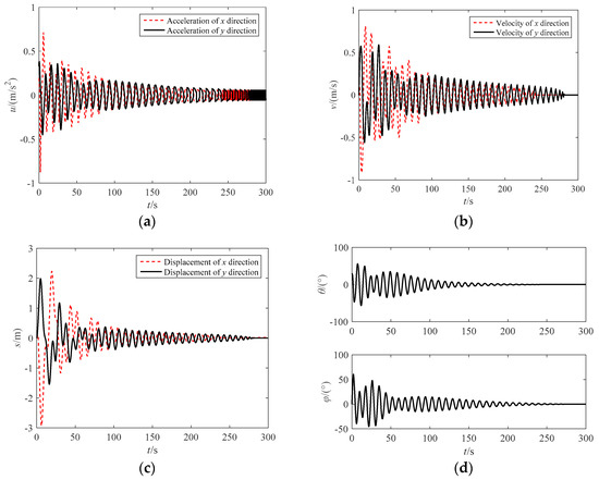
Figure 7.
Simulation results with VSC. (a) Acceleration of the towing point; (b) Velocity of the towing point; (c) Displacement of the towing point; (d) In-plane and out-of-plane swing angle of the target.
4. Experimental Study
The ground experiment system included two orthogonal linear guideways, two servo motors, a two-dimensional angle measuring mechanism, a flexible tether, a movable slider simulating the towing point and a weight simulating the target, as shown in Figure 8a. The movable slider could move on the XY-plane, which was driven by the two servo motors, as shown in Figure 8b. The weight was connected to the movable slider by a thin tether. The two swing angles were measured by the two-dimensional angle measuring mechanism. In the experiment, the starting position of the slider was close to the positive center of the XY-plane, which ensured that the movable distance of the slider in the direction of the two axes was not less than 0.4 m.
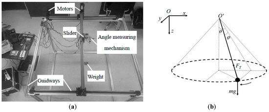
Figure 8.
Ground verification experiment of the anti-swing control. (a) Swing control ground experimental system; (b) Simplified Model.
The dynamical equation of the weight in the experimental system is obtained as follows:
It can be seen that Equations (25) and (1) have the same form. Hence, according to the dynamic similarity, the effectiveness of the control strategy can be verified by this ground experiment system. The anti-swing experiment was conducted with the feedback linearization controller. The experiment results are shown in Figure 9. The effectiveness of the triple closed-loop control strategy based on the feedback linearization control was verified. Because the input of the feedback linearization controller was independent in the X and Y direction, it can be known that the control strategy is effective for the swing motion caused by any initial swing angles.
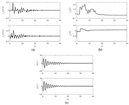
Figure 9.
Experiment results with the feedback linearation control. (a) Response of velocity; (b) Response of displacement; (c) Response of swing angles.
As analysed in Section 3.2, the dynamical equation can be approximated as a second-order specification system. Furthermore, based on approximate linearization control, the triple closed-loop control strategy can be used to stabilize the swing angles, velocity and displacement. The experimental results are shown in Figure 10. The in-plane and out-of-plane swing angles are stabilized in about 2°, and the velocity and displacement of the slider can be tracked steady.
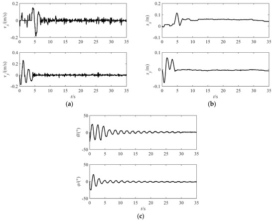
Figure 10.
Experiment results with the approximate linearation control. (a) Response of velocity; (b) Response of displacement; (c) Response of swing angles.
5. Conclusions
In this paper, the swing dynamical model of a space tethered combination in the maneuver process was established. The swing types of the space tethered combination were analyzed based on the dynamical model. Anti-swing control strategies based on linear feedback control, approximate linearization control and variable structure control were designed, based on the maneuver of the towing point. Compared with the feedback linearization control and approximate linearization control, there is a serious buffeting phenomenon in the variable structure control. The ground experiment system can simulate the swinging motion of the space tethered combination well, and the experimental results verified the effectiveness and the engineering feasibility of the feedback linearization control and the approximate swing control. In the future, adaptive PID and other intelligent control strategies can be used to suppress the swing of the space tethered combination.
Author Contributions
Funding
This research was funded by the National Natural Science Foundation of China, grant number 51805124, and the Zhejiang Provincial Natural Science Foundation of China, grant number LQ17E050011.
Acknowledgments
The authors would like to deliver their sincere thanks to the editors and anonymous reviewers.
Conflicts of Interest
The authors declare no conflict of interest.
References
- Liou, J.C.; Johnson, N.L. Planetary science-Risks in space from orbiting debris. Science 2006, 311, 340–341. [Google Scholar] [CrossRef] [PubMed]
- Flores-Abad, A.; Ma, O.; Pham, K.; Ulrich, S. A review of space robotics technologies for on-orbit servicing. Prog. Aerosp. Sci. 2014, 68, 1–26. [Google Scholar] [CrossRef]
- Xu, W.F.; Liang, B.; Xu, Y.S. Survey of modeling, planning, and ground verification of space robotic systems. Acta Astronaut. 2011, 68, 1629–1649. [Google Scholar] [CrossRef]
- Huang, P.F.; Zhang, F.; Cai, J.; Wang, D.K.; Meng, Z.J.; Guo, J. Dexterous tethered space robot: Design, measurement, control and experiment. IEEE Trans. Aerosp. Electron. Syst. 2017, 53, 1452–1468. [Google Scholar] [CrossRef]
- Bischof, B.; Kerstein, L. ROGER robotic geostationary orbit restorer. Sci. Technol. Ser. 2004, 109, 183–193. [Google Scholar]
- Pearson, J.; Carroll, J.; Levin, E.; Oldson, J.; Hausgen, P. Overview of the electrodynamic delivery expresses (EDDE). In Proceedings of the 39th AIAA/ASME/SAE/ASEE Joint Propulsion Conference & Exhibit, Huntsville, Alabama, 20–23 July 2003; AIAA: New York, NY, USA, 2003. [Google Scholar]
- Pearson, J.; Carroll, J.; Levin, E. Active debris removal: EDDE, the electrodynamic debris eliminator. In Proceedings of the 61st International Astronautical Congress, Prague, Czech Republic, 27 September–1 October 2010. SSI: 2010. [Google Scholar]
- Brophy, J.R.; Friedman, L.; Culick, F. Asteroid retrieval feasibility. In Proceedings of the 2012 IEEE Aerospace Conference, Big Sky, MT, USA, 3–10 March 2012. [Google Scholar]
- Brophy, J.R.; Culick, L.; Friedman, L. Asteroid Retrieval Feasibility Study; The University of Arizona Press: Tucson, AZ, USA, 2012. [Google Scholar]
- Nakasuka, S.; Funase, R.; Nakada, K.; Kaya, N.; Mankins, J.C. Large membrane “Furoshiki Satellite” applied to phased array antenna and its sounding rocket experiment. Acta Astronaut. 2006, 58, 395–400. [Google Scholar] [CrossRef]
- Nakasuka, S.; Aoki, T.; Ikeda, I.; Tsuda, Y.; Kawakatsu, Y. “Furoshiki satellite”-a large membrane structure as a novel space system. Acta Astronaut. 2001, 48, 461–468. [Google Scholar] [CrossRef]
- Wen, H.; Zhu, Z.H.; Jin, D.P.; Hu, H.Y. Constrained tension control of a tethered space-tug system with only length measurement. Acta Astronaut. 2016, 119, 110–117. [Google Scholar] [CrossRef]
- Wang, B.; Guo, J.F.; Yi, L.; Zhou, W.H. Anti-impact tension control strategy for the space-tethered combination after target capture. Aeronaut. J. 2018, 122, 1775–1787. [Google Scholar] [CrossRef]
- Williams, P. In-plane payload capture with an elastic tether. J. Guid. Control. Dyn. 2006, 29, 810–821. [Google Scholar] [CrossRef]
- Felisiak, P.A.; Sibilski, K.S.; Qin, K.; Li, G.; Wróblewski, W.A. Nonlinear model predictive control of spacecraft relative motion. Proc. Inst. Mech. Eng. Part. G J. Aerosp. Eng. 2019, 233, 3906–3919. [Google Scholar] [CrossRef]
- Jasper, L.; Schaub, H. Input shaped large thrust maneuver with a tethered debris object. Acta Astronaut. 2014, 96, 128–137. [Google Scholar] [CrossRef]
- Jasper, L.; Schaub, H. Tethered towing using open-loop input-shaping and discrete thrust levels. Acta Astronaut. 2014, 105, 373–384. [Google Scholar] [CrossRef]
- Aslanov, V.; Yudintsev, V. Dynamics of large space debris removal using tethered space tug. Acta Astronaut. 2013, 9, 149–156. [Google Scholar] [CrossRef]
- Aslanov, V.; Yudintsev, V. Dynamics of large debris connected to space tug by a tether. J. Guid. Control. Dyn. 2013, 36, 1654–1660. [Google Scholar] [CrossRef]
- Liu, H.T.; Zhang, Q.B.; Yang, L.P.; Zhu, Y.W.; Zhang, Y.W. Dynamics of tether-tugging reorbiting with net capture. Sci. China Technol. Sci. 2014, 57, 2407–2417. [Google Scholar] [CrossRef]
- Wang, B.; Guo, J.F.; Feng, J.G.; Wang, J. Nonlinear dynamics and coupling effect of libration and vibration of tethered space robot in deorbiting process. J. Cent. South. Univ. 2016, 23, 1095–1105. [Google Scholar] [CrossRef]
- Zhao, G.W.; Sun, L.; Tan, S.P.; Huang, H. Librational characteristics of a dumbbell modeled tethered satellite under small, continuous, constant thrust. Proc. Inst. Mech. Eng. Part. G J. Aerosp. Eng. 2012, 227, 857–872. [Google Scholar] [CrossRef]
- Sun, L.; Zhao, G.W.; Huang, H. Stability and control of tethered satellite with chemical propulsion in orbital plane. Nonlinear Dyn. 2013, 74, 1113–1131. [Google Scholar] [CrossRef]
- Liu, H.L.; He, Y.Z.; Yan, H.; Tan, S.P. Tether tension control law design during orbital transfer via small-gain theorem. Aerosp. Sci. Technol. 2017, 63, 191–202. [Google Scholar] [CrossRef]
- De Juan, D.P. Lie derivatives and structure Jacobi operator on real hypersurfaces in complex projective spaces. Differ. Geom. Appl. 2017, 50, 1–10. [Google Scholar]
© 2020 by the authors. Licensee MDPI, Basel, Switzerland. This article is an open access article distributed under the terms and conditions of the Creative Commons Attribution (CC BY) license (http://creativecommons.org/licenses/by/4.0/).