Article

A New Method of Contact Stress Measurement for Analyzing Internal Impingement Syndrome of the Shoulder: Potentials and Preliminary Evaluation

1
BioComputing Laboratory, Department of Computer Science and Engineering, Institute for Bioengineering Application Technology, Korea University of Technology and Education (KOREATECH), Cheonan 31253, Korea
2
Camp 9 Orthopedic Clinic, Hwaseong 18505, Korea
*
Author to whom correspondence should be addressed.
Appl. Sci. 2020, 10(12), 4165; https://doi.org/10.3390/app10124165
Submission received: 30 April 2020 / Revised: 13 June 2020 / Accepted: 15 June 2020 / Published: 17 June 2020
(This article belongs to the Special Issue Applied Biomechanics in Sport, Rehabilitation and Ergonomy)

Abstract

:
Shoulder impingement syndrome causes critical disorders such as rotator cuff tear or superior labrum anterior to posterior (SLAP) lesion in both the general public and in athletes whose sports involve throwing. Nevertheless, the biomechanics of the syndrome still have not been clarified. Contact stress measurement in vivo during shoulder motion is essential to identifying the biomechanics of the syndrome. There have been no reports to date regarding internal impingement syndrome among the syndrome studied by using the finite element method (FEM). The proposed method simulates the internal impingement syndrome according to shoulder motion using the FEM. The method solves the critical process zone error at the supraspinatus tendon insertion according to impingement of the 3D biomechanical model by relaxing the boundary condition for representation of shoulder motion. The simulation results confirmed that the proposed method allowed for the analysis of internal impingement syndrome by measuring contact stress (23.13 MPa) during shoulder motion. The performance of the proposed method was examined through the differential displacement (maximum 3.28 mm) in shoulder motion by boundary condition relaxation. The result of the simulation was consistent with the clinical findings.

1. Introduction

Shoulder impingement syndrome causes supraspinatus tendon injury to throwing athletes such as baseball players [1,2]. The syndrome is also present in the general public, including computer workers and the elderly, as well as elite athletes engaged in throwing activities [3,4,5]. Recently, studies are underway to identify the main causal factors in shoulder impingement syndrome and to develop appropriate prevention and treatment plans.
The clinical cause of shoulder impingement syndrome has been known as supraspinatus tendon injury, caused by contact between musculoskeletal tissues inside the joint (subacromial space) [6]. However, the biomechanical mechanism still has not been clarified [2,7,8]. This study, which aims to identify the biomechanical mechanism of shoulder impingement syndrome, is essential in that supraspinatus tendon injury can lead to additional critical disorders such as rotator cuff [9,10,11,12] or superior labrum anterior to posterior (SLAP) tears [13,14,15]. Typically, shoulder impingement syndrome consists of both external and internal impingement syndromes. External impingement syndrome involves a lesion or injury of the supraspinatus tendon caused by contact with the acromion at subacromial space. External impingement syndrome cannot explain posterior shoulder pain during shoulder motion. Internal impingement syndrome analyses are required to explain posterior shoulder pain. Internal impingement syndrome involves a lesion or injury of the supraspinatus tendon caused by contact between the labrum and humeral head during shoulder motion. Internal impingement syndrome is thought to be fundamentally complex and multifactorial in its explanation of posterior shoulder pain [2].
Traditional studies for internal impingement syndrome estimate the mechanism of shoulder impingement syndrome through various methods based on arthroscopic findings, image diagnoses, and cadaveric experiments. The arthroscopic finding-based method [16] involves invasive observations of the interactions between musculoskeletal tissues in vivo. This method has the disadvantage that it cannot be used to experiment for injuries of soft tissues because of ethical issues. The image diagnosis-based method [3,6] noninvasively analyzes soft tissues in vivo by using medical imaging information scanned from magnetic resonance imaging (MRI) results. However, this method has a low accuracy problem because it measures the three-dimensional (3D) shape of internal impingement syndrome on a two-dimensional (2D) image. The cadaveric experiment-based method [14,17] measures the deformation of musculoskeletal tissues by using a mechanical device. This method has a low reliability problem because it is difficult to obtain sufficient samples [18]. In other words, these methods are not suitable for the analysis of shoulder impingement syndrome because the arthroscopic finding-, image diagnosis-, and cadaveric experiment-based methods cannot measure the contact stress that occurred in vivo in the shoulder joint.
Conventional studies are underway to analyze the biomechanical mechanism of shoulder impingement syndrome through computer simulations by using the finite element method (i.e., FE simulations). The FE simulations allow us to analyze the injury of musculoskeletal tissue in vivo by using a 3D biometric model. This method measures the contact stress between musculoskeletal tissues in vivo.
As above, most of the previous studies have focused on external impingement syndrome among the shoulder impingement syndromes. Specifically, there were no reports found of internal impingement syndrome among the shoulder impingement syndromes studied by using the finite element method.
In this paper, we propose a new contact stress measurement method for analyzing internal impingement syndrome of the shoulder. The proposed method simulates internal impingement syndrome of the supraspinatus tendon between the humeral head and labrum based on the finite element method. This allows for the analysis of internal impingement syndrome by measuring contact stress during shoulder motion. The performance of the proposed method is examined through a differential displacement of the humerus according to shoulder motion.

2. Materials and Methods

2.1. Design and Setting

The proposed method is designed in the following four steps, as shown in Figure 1: (1) shoulder geometric data acquisition; (2) shoulder material property representation; (3) boundary and loading condition definition for humeral motion and supraspinatus tendon loading; (4) boundary condition relaxation for humeral motion. Steps 1–3 of the proposed method have referred to the traditional shoulder modeling method and are applied to FE simulation [19].
In the first step, the geometry of the shoulder model, including bones (humerus and scapula) and soft tissues (supraspinatus tendon and labrum), is reconstructed based on medical imaging information. Material properties of cartilage are considered as those of bone according to the assumption that it does not affect the simulation results [20,21]. Herein, the medical imaging information includes computerized tomography (CT), computerized tomography arthrogram (CTA), and magnetic resonance (MR) images. Bone models of the humerus and scapula are derived from the CT images. The soft tissue models of the supraspinatus tendon and labrum are derived from the CTA and MR images. The soft tissue models are constructed by stacking the contours extracted according to the consultation of orthopedic surgeons [22]. The medical imaging information is acquired in three planes (axial, coronal, and sagittal planes). The accuracy of the shoulder model is enhanced by combining the models represented based on three planes.
In the second step, the material properties are applied to the shoulder model to represent the deformation of in vivo properties. The material properties are included in vertices of the elements consisting of shoulder models. The humeral and scapular models are assumed to be rigid body material because bone has extremely high stiffness compared to soft tissues. The material property of the labrum is modeled as linear elasticity with isotropy and homogeneity, and that of the supraspinatus tendon is modeled as hyperelasticity considering the large deformations. The material properties used in the shoulder model were referenced from the conventional literature [23,24,25,26], and details are shown in Table 1.
In the third step, the boundary and load conditions are defined to represent shoulder motion, as shown in Figure 2. The boundary condition is humeral abduction, generated based on screw motion. Generally, the screw motion is used to represent the shoulder motion based on Chasles’ theorem [27]. Because actual shoulder motion is not rotated based on spherical coordinates, it is hard to represent humeral abduction among musculoskeletal tissue. To solve this, the humeral abduction is represented as a screw motion between two postures (neutral position and abducted position). The humeral model superimposed on the scapula model among bone models was derived based on CT images scanned from the two postures, and it was used in the screw motion of the humerus. The represented humeral abduction is achieved as rotation and translation on the basis of the screw axis. The load condition is pretension pulled from the distal to proximal side of the supraspinatus tendon, and this is performed simultaneously with humeral abduction.
Fine modeling and motion generation are important because FE simulations are affected by geometry and motion trajectory [28]. However, an error occurred in the critical process zone of the insertion site of the supraspinatus tendon in FE simulations based on the conventional method (steps 1 to 3), as shown in Figure 3a. The error is indicated when excessive distortion of the supraspinatus tendon model occurs because of specific rotational movements of the humeral model, as shown in Figure 3b. Furthermore, excessive distortion in the numerical analysis often interrupts calculations. This can be attributed to a computational stability problem caused by compression of the soft tissue model between the humeral and scapular models, along with the displacement boundary condition. This problem makes the volume of soft tissues approach zero, and thus, the accuracy decreases in FE simulations. According to the conventional study [10] that quantifies the injury caused by partial-thickness tears of the supraspinatus tendon, the injury begins at the insertion site. This supports that the error occurs on critical process zones.
In the fourth step, this problem can be solved by relaxing the displacement boundary condition of the humeral model to prevent excessive deformation. By using the Abaqus VUEL commercial computer program, we developed a method that enables relaxation of the boundary condition in accordance with the interactions of adjacent materials while adhering to the desired boundary condition. The method of the displacement boundary condition relaxation can be explained as a hybrid concept that combines the tie conditions for two nodes of the Abaqus *MPC (multi-point constraints) commands and elastic flexibility, as shown in Figure 4. The first step involved constructing a dummy identical to the object whose displacement boundary condition was to be monitored. The same boundary condition was then applied to this dummy model in the corresponding location. A line connecting the same location in the real humerus model (follower) and dummy model (guide) was established. This line was assumed to be a two-node truss element, whose property is defined as a “user element” (VUEL). The property of this user element is defined as follows. If the two endpoints show different displacement values, resistance is generated in proportion to the amount of difference by applying a penalty function. If the penalty function is sufficiently large, interactions between the adjacent materials do not interfere with the entered displacement boundary. However, if the penalty function is too weak, slight differences in displacement may occur between the two endpoints in cases of interaction.
The penalty function is assumed to have types of potential energy, including kinetic energy, with the following Hamilton principle.
Φ = T V = t 1 t 2 ( 1 2 m 1 u ˙ 1 · u ˙ 1 + 1 2 m 2 u ˙ 2 · u ˙ 2 ( ( P 1 · u 1 P 2 · u 2 + 0 u ( t ) f ( u 2 u 1 ) · d ( u 2 u 1 ) ) ) d t
Kinetic energy is denoted by T, and potential energy exerted by the external force and the strain energy are represented by V. The truss element has two nodes and the subscript denotes the node index. ( u 2 u 1 ) denotes the difference in the displacement vector of nodes 1 and 2 of the truss.
Along the equation of motion, the variation of the penalty function will vanish.
δ Φ = δ t 1 t 2 ( 1 2 m 1 u ˙ 1 · u ˙ 1 + 1 2 m 2 u ˙ 2 · u ˙ 2 ( P 1 · u 1 P 2 · u 2 + 0 u ( t ) f ( u 2 u 1 ) · d ( u 2 u 1 ) ) ) d t
After taking the variation on each term and using the integral by part, the following conditions can be established for each node:
P 1 f ( u 2 u 1 ) + m 1 u ¨ 1 = 0
P 2 + f ( u 2 u 1 ) + m 2 u ¨ 2 = 0
These equations imply that external, internal, and inertial forces are physically balanced in equilibrium. If acceleration can be ignored and the current position deviates from the position in equilibrium, Taylor expansion can be applied in the vicinity of the current position, which yields the following equation.
[ f ( u 2 u 1 ) 0 f ( u 2 u 1 ) 0 f ( u 2 u 1 ) 0 f ( u 2 u 1 ) 0 ] [ δ u 1 δ u 2 ] = [ P 1 + f ( u 2 u 1 ) 0 P 2 + f ( u 2 u 1 ) 0 ]
[ P 1 + f ( u 2 u 1 ) 0 P 2 f ( u 2 u 1 ) 0 ]   is the force in the initial position, and f ( u 2 u 1 ) 0 is the differential of the function in the initial position. If the function of internal force f ( u 2 u 1 ) is assumed to have a linear functional form, the strain energy relative to the x, y, z direction components of the displacement can be expressed by 1 2 K x ( x 2 x 1 ) 2 + 1 2 K y ( y 2 y 1 ) 2 + 1 2 K z ( z 2 z 1 ) 2 .
In this case,
[ K x 0 0 0 K y 0 0 0 K z K x 0 0 0 K y 0 0 0 K z K x 0 0 0 K y 0 0 0 K z K x 0 0 0 K y 0 0 0 K z ] [ δ u 1 x δ u 1 y δ u 1 z δ u 2 x δ u 2 y δ u 2 z ] = [ P 1 x + f x ( u 2 u 1 ) 0 P 1 y + f y ( u 2 u 1 ) 0 P 1 z + f z ( u 2 u 1 ) 0 P 2 x + f x ( u 2 u 1 ) 0 P 2 y + f y ( u 2 u 1 ) 0 P 2 z + f z ( u 2 u 1 ) 0 ]
or [ K ] [ δ u ] = [ F ] can be used as the matrix form. If a positive-definite system is used, changes in the penalty function relative to changes in δ u are negative or zero, as per Equation (2). In other words,
δ Φ = [ P 1 f ( u 2 u 1 ) P 2 + f ( u 2 u 1 ) ] [ δ u 1 δ u 2 ] = [ P 1 f ( u 2 u 1 ) P 2 + f ( u 2 u 1 ) ] [ K ] 1 [ P 1 + f ( u 2 u 1 ) P 2 f ( u 2 u 1 ) ] 0
If acceleration cannot be ignored in Equations (3) and (4), Equation (8) is solved by applying an explicit method.
[ m 1 0 0 m 2 ] [ u ¨ 1 u ¨ 2 ] = [ P 1 + f ( u 2 u 1 ) P 2 f ( u 2 u 1 ) ]
After obtaining the acceleration of nodes 1 and 2, the resulting value is integrated to obtain the displacement in the next time step [29,30].
In Abaqus/Explicit user element (VUEL) subroutines, a mass matrix and force matrix can be computed with the values entered. These values can include the initial positions of the nodes pertaining to an element, displacement relative to the initial position, and incremental displacement at the current time increment t . In this study, to ignore the inertial force generated by mass, the mass of the truss element was set to a low value. However, this value should have been sufficiently high to ensure a sufficient time increment because it was related to the frequency of the motion, according to the following Equation (9).
t = min ( L e ρ E ) = min ( M e K e )
The force matrix is calculated from the right term of Equation (8).

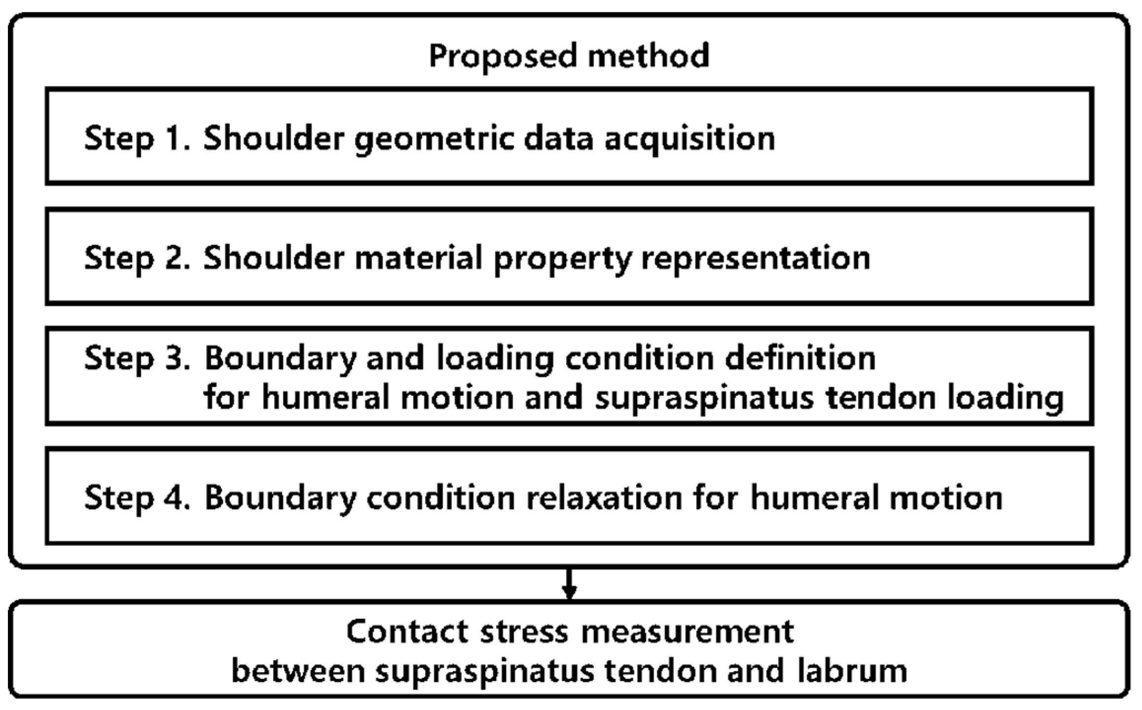
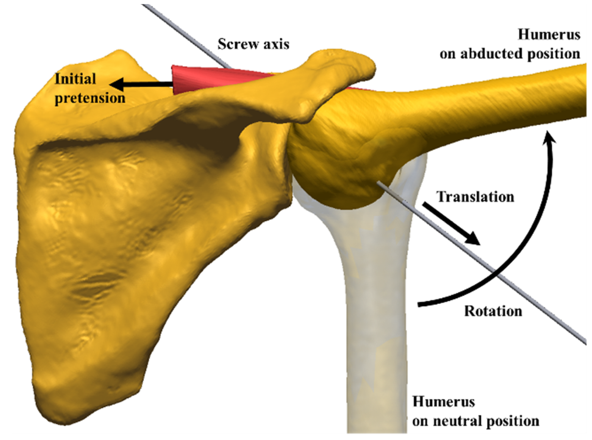
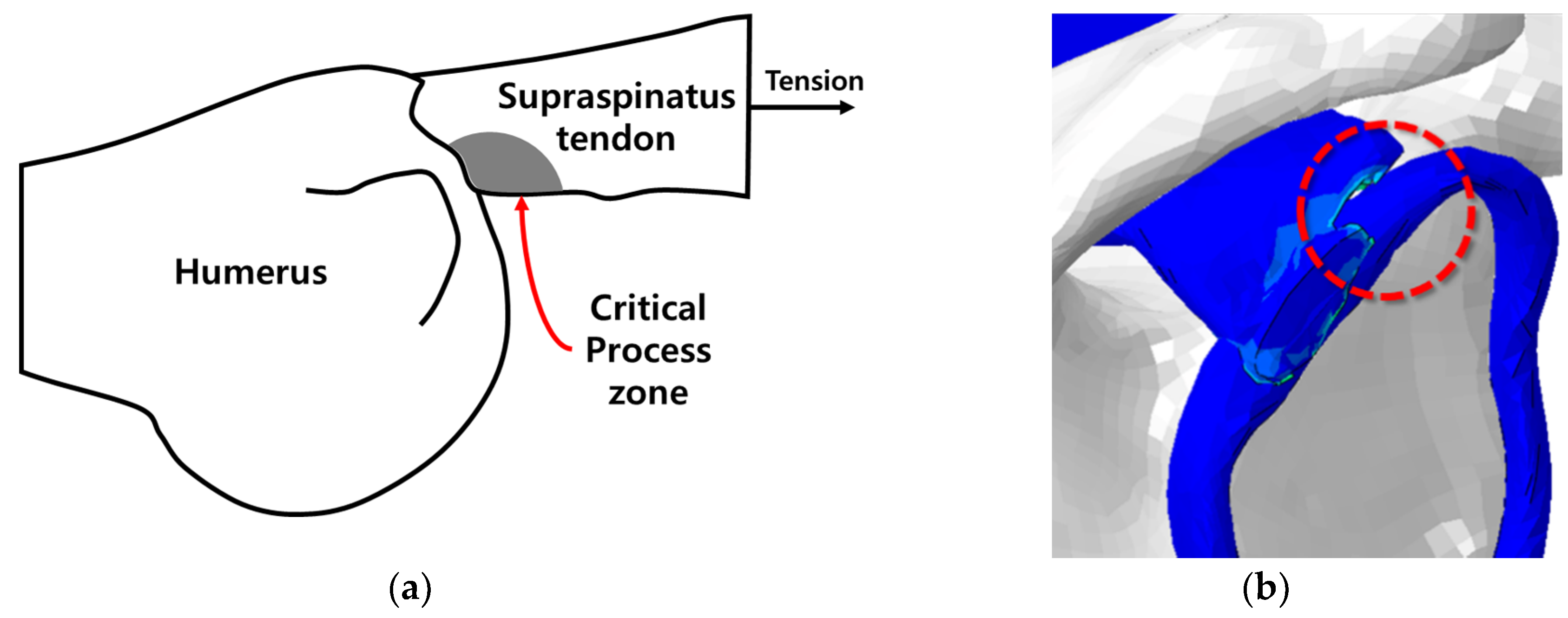
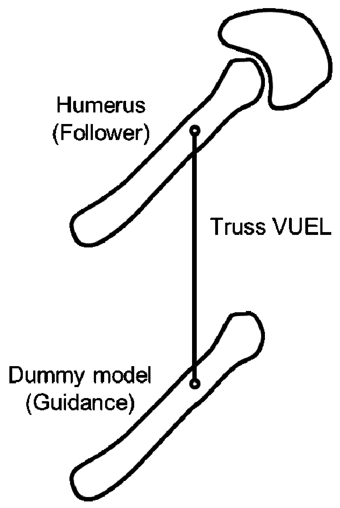
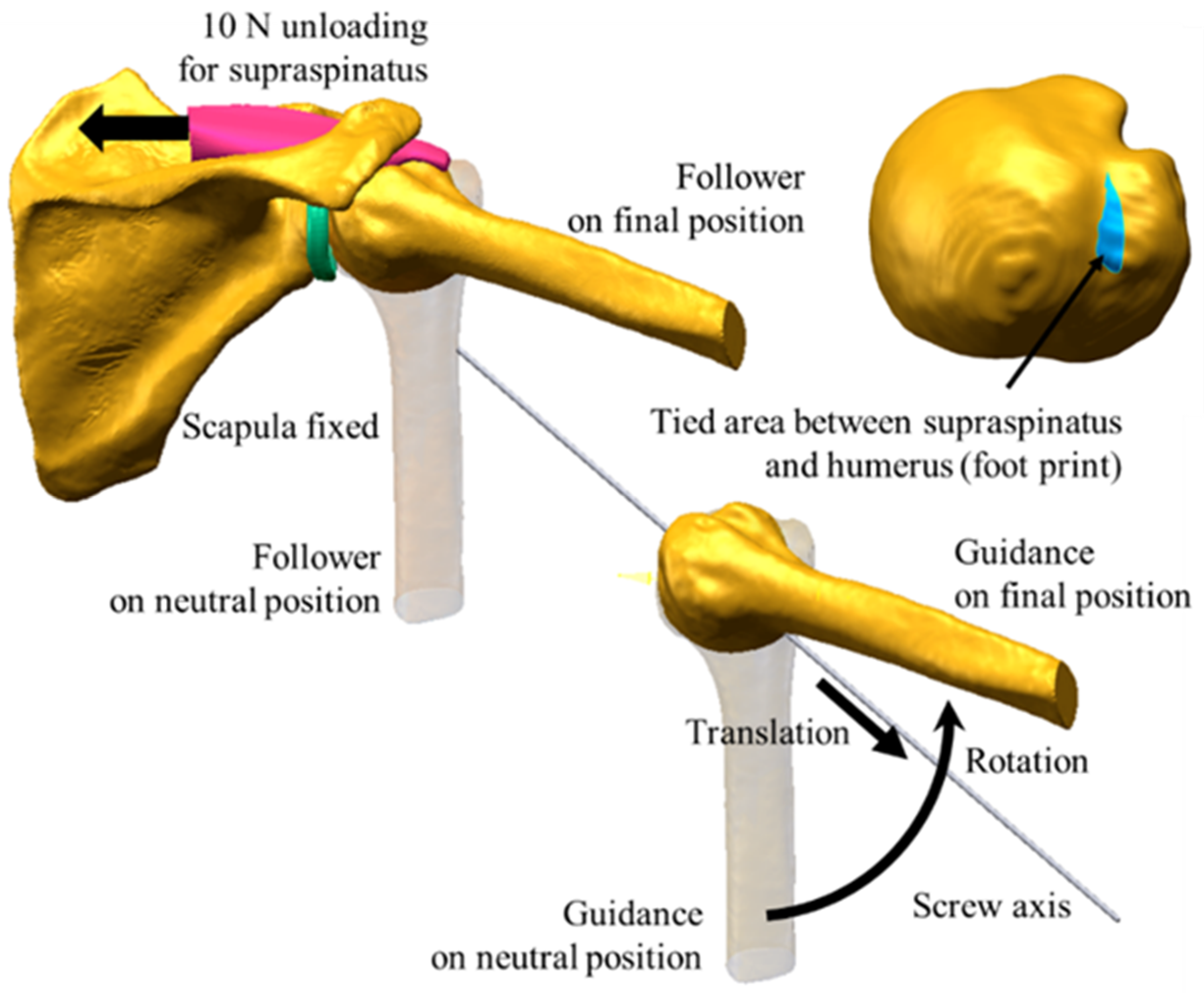
2.2. Finite Element Simulation
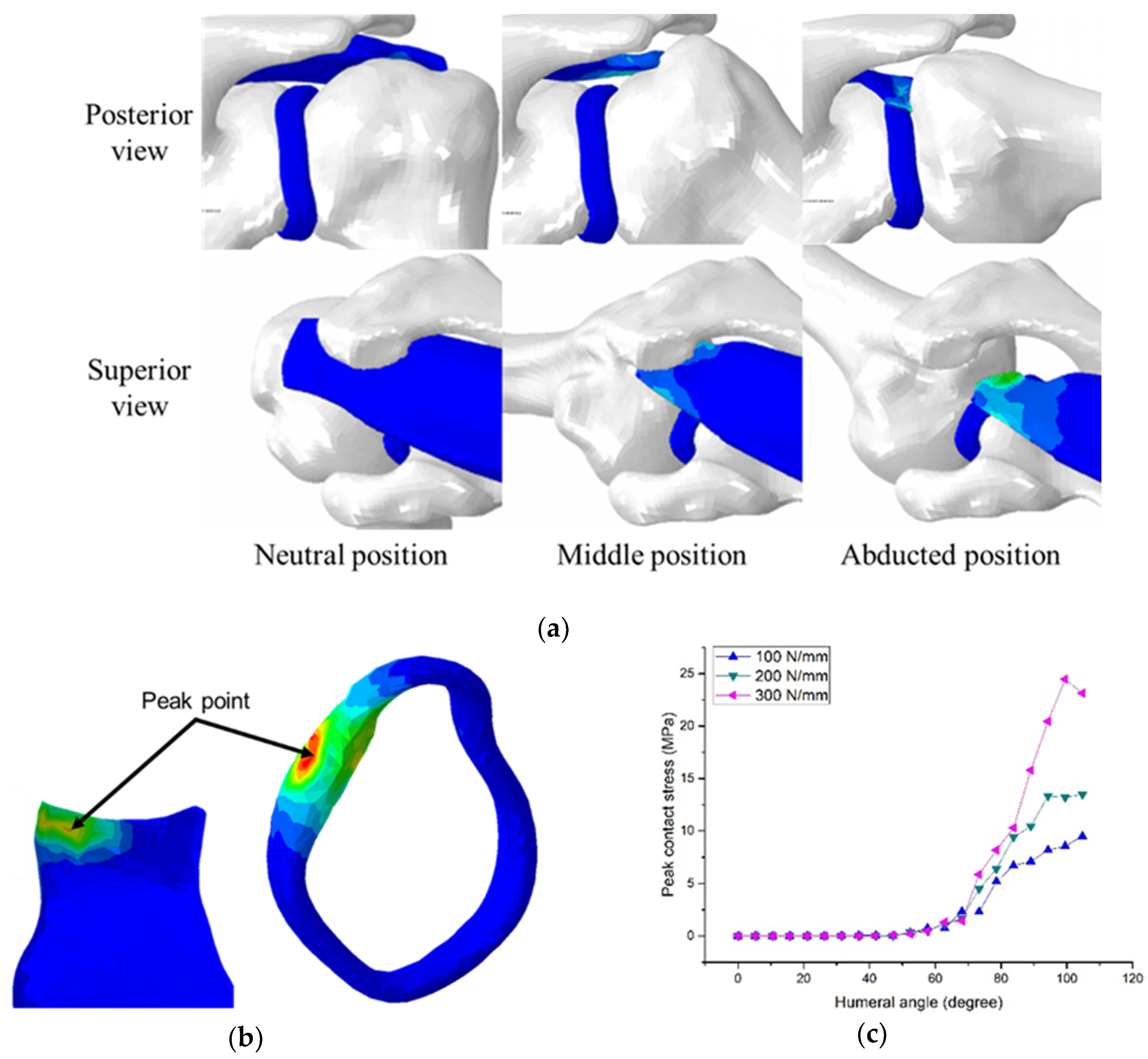
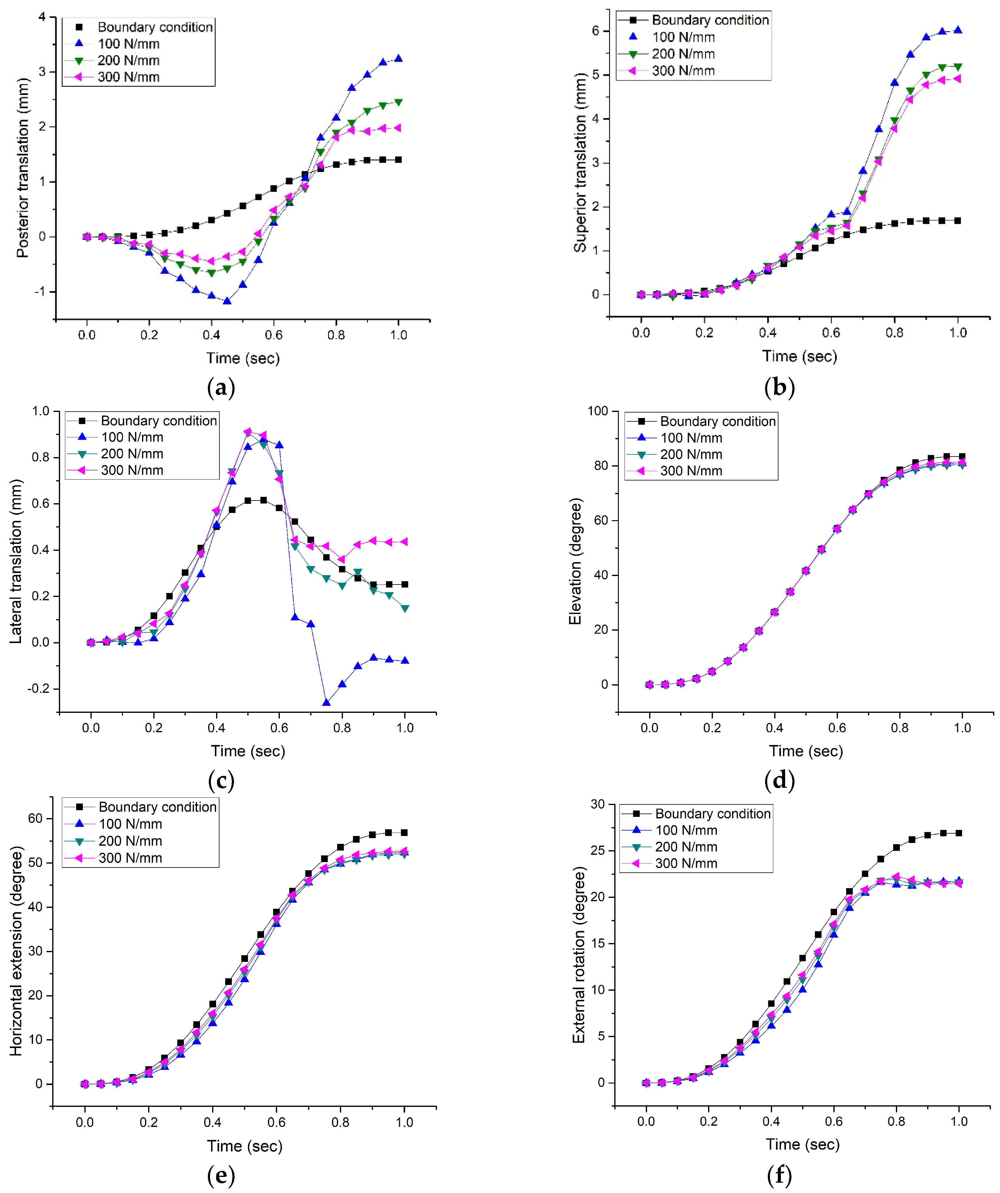
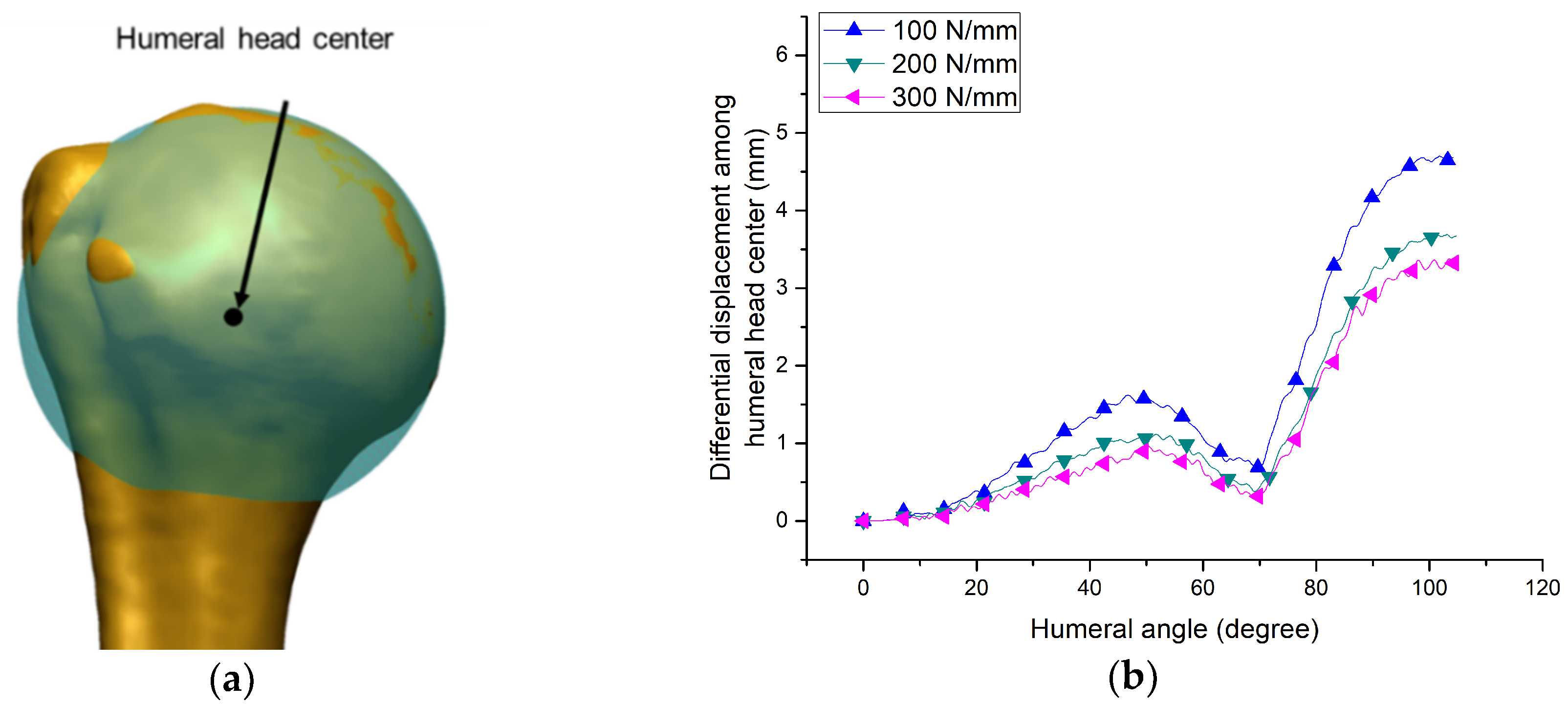
The FE simulations applied with the proposed method were performed in an environment, including humeral motion, pretension of the supraspinatus tendon, and miscellaneous conditions, as shown in Figure 5. The humeral motion is generated by screw motion with relaxation control of the boundary condition. The dummy model for the relaxation control of the displacement boundary condition in the FE modeling is defined as the guidance for humeral motion. The humeral model, the actual object of analysis, is defined as the follower. Additionally, the proximal end of the supraspinatus tendon is pulled constantly by a force of 10 N to maintain pretension [31]. The miscellaneous conditions include scapular fixation, a tie condition, and a contact condition. The scapular, which is the basis of humeral motion, is fixed at the initial position. The humerus and supraspinatus tendon are tied based on the footprint. In the contact condition between soft tissues, the applied coefficient of friction is 0 to represent slip caused by actual moisture. The bone models, defined as a rigid body, are modeled by linear quadrilateral elements, which are shell elements (S4), in order to reduce the computations. The soft tissue models, which are likely to come into contact with one another, are modeled by linear tetrahedron elements (C3D4).
Table 2 is pseudo-code of FE simulation applied with the proposed method. The spring constant (K) of truss is assumed to be K x = K y = K z , which is an isotropic feature, and be analyzed step by step. If spring constants are increased, the synchronization between the guidance model and follower model increases, and this can come close to the case where the displacement boundary condition is given directly to the analyzed model.

3. Results

We constructed the proposed method and successfully simulated it, as shown in Figure 6. If the displacement boundary condition is relaxed by a truss element, the excessive element destruction at the soft tissue can be prevented at the point where the binding force of truss and the reaction from the supraspinatus tendon and scapula reach a balance between one another.
Figure 6a shows the result of simulation, where the relaxation control of the displacement boundary condition is applied to the glenohumeral joint. The peak contact stresses were measured at the final position and at a peak point where the contact stress on the labrum was highest, as shown in Figure 6b. Figure 6c presents a peak stress change curve between the supraspinatus tendon and the labrum according to humeral motion. The peak contact stresses measured at final motion, with spring constants of 100, 200, and 300 N/mm, were 9.49, 13.47, and 23.13 MPa, respectively. As a result, the stress distribution is concentrated at the point where the posterosuperior labrum impinges on the supraspinatus tendon, and the measurements of peak stress showed that contact stress increases with the increase in the spring constant.
Figure 7 shows the comparison of the boundary condition (the guidance) and the humeral motion (the follower) by the proposed method: The boundary condition is the humeral motion of the 6-DOF (degree of freedom), including the translation (posterior, superior, lateral one) and rotation (elevation, horizontal extension, external rotation). The humeral motion of the 6-DOF was represented with reference to the joint coordinate system of ISB recommendation [32].
The performance of the proposed method was examined from the differential displacement. The differential displacement means that distance between the displacement of humeral head centers (the guidance and follower). We defined the humeral head center as the center of a sphere that fits the humeral head, as shown in Figure 8a. Figure 8b shows the change in the distance between the humeral head centers of the guidance and follower according to humeral angles. When the humeral angle is small, the distance between the humeral head centers is close to zero. However, after a certain degree of rotation is generated, the distance between the guidance and follower becomes clear because of the surrounding reaction. The distances between the centers measured at final motion, with spring constants of 100, 200, and 300 N/mm, were 4.68, 3.67, and 3.28 mm, respectively. This means that the proposed method allows for FE simulations of shoulder motion with a differential displacement of 3.28 mm.

4. Discussion

4.1. Principal Results

In this study, we proposed a new method of contact stress measurement for the analysis of shoulder internal impingement syndrome. The traditional FE simulations for shoulder motion consist of geometric data acquisition, material property representation, boundary and loading condition definition, and experimental validation [19]. The FE simulations (three steps), except for the experimental validation step, were problematic in that they could not simulate excessive distortion of the models such as that due to shoulder motion. Therefore, the proposed method focused on the control of shoulder motion to enable simulations with excessive distortion of the model.
The proposed method solved the critical process zone error of supraspinatus tendon insertion due to excessive distortion of the 3D biomechanical model by relaxing the boundary condition for shoulder motion representation. Boundary condition relaxation is useful for calculations when representing complex musculoskeletal structures, such as the human shoulder complex. Hereby, this allowed for contact stress measurements in vivo, which was impossible to do in conventional studies based on motion analysis and cadaveric experiments. The peak contact stress measured from the simulation results was 23.13 MPa, with spring constants of 300 N/mm. The measurement result was similar to ultimate stress (26.60 Mpa) of the supraspinatus tendon, which was measured in the cadaveric environment of Itoi et al. [33]. The performance of the proposed method was examined through the differential displacement (maximum 3.28 mm) in shoulder motion by boundary condition relaxation. The differential displacement was similar to the translation (3.73 mm) of the humeral head center, which Massimini et al. [33] measured using biaxial fluoroscopy. This means that it is possible to analyze internal impingement syndrome in the shoulder motion process. From the analysis results of internal impingement syndrome, strong contact was observed between posterosuperior labrum and undersurface of the posterior supraspinatus tendon. The analysis results are consistent with the findings of Jobe [6], who described the junction of the posterior supraspinatus and anterior infraspinatus tendons as a highly vulnerable area [22].

4.2. Limitations

The limitation of this study is that the proposed method has not been experimentally validated. Experimental verification for typical FE simulations would require the use a cadaver rather than a living body. However, cadaveric experiments have low reliability because a living body and cadavers have different material properties. Therefore, this study is more meaningful than the conventional method in that it simulates based on the motion of a living body from a new perspective. Moreover, the material properties are not accurate because a nonlinear hyperelastic model is used, which does not consider viscosity and shear force, and the precision of the FE simulation result is low because a shoulder model (case) of only one subject was used. Although the proposed method has a large error, it can be expected to provide basic data with high precision and accuracy if the number of cases is increased and the material model is improved.

5. Conclusions

In this study, we proposed a new contact stress measurement method for analyzing internal impingement syndrome of the shoulder. The proposed method simulates impingement syndrome of the supraspinatus tendon between the humeral head and labrum based on the finite element method. Inaccurate trajectory of shoulder motion causes impingement of the humerus and scapula, and this can influence the structure of soft tissues within the shoulder. To solve this problem, in this study, the humeral motion is given a degree of freedom through the connection of truss elements between the guidance and follower, which are based on user-defined elements. This allows for the analysis of internal impingement syndrome by measuring contact stress during shoulder motion. To date, there is no such study to our knowledge that utilizes FE simulations to analyze internal impingement syndrome. The proposed method is significant in that it opens the door for future researchers to explore the phenomenon of posterior shoulder pain more completely.

Author Contributions

Conceptualization, Y.-S.Y.; Formal analysis, Y.-S.Y.; Methodology, S.-w.J.; Supervision, Y.S.K.; Visualization, S.-w.J.; Writing—original draft, S.-w.J.; Writing—review and editing, Y.S.K. All authors have read and agree to the published version of the manuscript.

Funding

This research received no external funding.

Conflicts of Interest

The authors declare no conflict of interest.

References

  1. Ludewig, P.M.; Reynolds, J.F. The association of scapular kinematics and glenohumeral joint pathologies. J. Orthop. Sports Phys. Ther. 2009, 39, 90–104. [Google Scholar] [CrossRef] [PubMed] [Green Version]
  2. Heyworth, B.E.; Williams, R.J. Internal impingement of the shoulder. J. Sports Med. 2009, 37, 1024–1037. [Google Scholar] [CrossRef] [PubMed]
  3. Halbrecht, J.L.; Tirman, P.; Atkin, D. Internal impingement of the shoulder: Comparison of findings between the throwing and nonthrowing shoulders of college baseball players. Arthroscopy 1999, 15, 253–258. [Google Scholar] [CrossRef]
  4. Borsa, P.A.; Wilk, K.E.; Jacobson, J.A.; Scibek, J.S.; Dover, G.C.; Reinold, M.M.; Andrews, J.R. Correlation of range of motion and glenohumeral translation in professional baseball pitchers. J. Sports Med. 2005, 33, 1392–1399. [Google Scholar] [CrossRef]
  5. Ostrander, R.; Escamilla, R.F.; Hess, R.; Witte, K.; Wilcox, L.; Andrews, J.R. Glenohumeral rotation deficits in high school, college, and professional baseball pitchers with and without a medial ulnar collateral ligament injury. J. Shoulder Elb. Surg. 2019, 28, 423–429. [Google Scholar] [CrossRef]
  6. Jobe, C.M. Posterior superior glenoid impingement: Expanded spectrum. Arthroscopy 1995, 11, 530–536. [Google Scholar] [CrossRef]
  7. Spiegl, U.J.; Warth, R.J.; Millett, P.J. Symptomatic internal impingement of the shoulder in overhead athletes. Sports Med. Arthrosc. Rev. 2014, 22, 120–129. [Google Scholar] [CrossRef] [Green Version]
  8. Mackenzie, T.A.; Herrington, L.; Horlsey, I.; Cools, A. An evidence-based review of current perceptions with regard to the subacromial space in shoulder impingement syndromes: Is it important and what influences it? Clin. Biomech. 2015, 30, 641–648. [Google Scholar] [CrossRef]
  9. Seo, Y.J.; Yoo, Y.S.; Kim, D.Y.; Noh, K.C.; Shetty, N.S.; Lee, J.H. Trans-tendon arthroscopic repair for partial-thickness articular side tears of the rotator cuff. Knee Surg. Sports Traumatol. Arthrosc. 2011, 19, 1755–1759. [Google Scholar] [CrossRef]
  10. Engelhardt, C.; Ingram, D.; Müllhaupt, P.; Farron, A.; Becce, F.; Pioletti, D.; Terrier, A. Effect of partial-thickness tear on loading capacities of the supraspinatus tendon: A finite element analysis. Comput. Methods Biomech. Biomed. Eng. 2016, 19, 875–882. [Google Scholar] [CrossRef] [Green Version]
  11. Huang, C.Y.; Stankiewicz, A.; Ateshian, G.A.; Mow, V.C. Anisotropy in homogeneity and tension–compression nonlinearity of human glenohumeral cartilage in finite deformation. J. Biomech. 2005, 38, 799–809. [Google Scholar] [CrossRef] [PubMed] [Green Version]
  12. Thunes, J.; Miller, R.M.; Pal, S.; Damle, S.; Debski, R.E.; Maiti, S. The effect of size and location of tears in the supraspinatus tendon on potential tear propagation. J. Biomech. 2015, 137, 081012. [Google Scholar] [CrossRef] [PubMed]
  13. Sreehari, C.K.; Varshney, A.; Yoo, Y.S.; Lee, S.J. Arthroscopic intra-articular spinoglenoid cyst resection following SLAP repair. Arthrosc. Tech. 2017, 6, e1795–e1799. [Google Scholar]
  14. Jobe, C.M.; Sidles, J. Evidence for a Superior Glenoid Impingement upon the Rotator Cuff: Anatomic, Kinesiologic, MRI and Arthroscopic Findings. In Proceedings of the 5th International Conference on Surgery of the Shoulder, Paris, France, 12–15 July 1992. [Google Scholar]
  15. Burkhart, S.S. Internal impingement of the shoulder. Instr. Course Lect. 2006, 55, 29–34. [Google Scholar]
  16. Walch, G.; Boileau, P.; Noel, E.; Donell, S.T. Impingement of the deep surface of the supraspinatus tendon on the posterosuperior glenoid rim: An arthroscopic study. J. Shoulder Elb. Surg. 1992, 1, 238–245. [Google Scholar] [CrossRef]
  17. Mihata, T.; Gates, J.; McGarry, M.H.; Neo, M.; Lee, T.Q. Effect of posterior shoulder tightness on internal impingement in a cadaveric model of throwing. Knee Surg. Sports Traumatol. Arthrosc. 2015, 23, 548–554. [Google Scholar] [CrossRef]
  18. Decker, S.; Ford, J. Accuracy and reliability of soft tissue depth measurements from CT for forensic facial reconstruction. J. Forensic Radiol. Imaging 2013, 1, 82. [Google Scholar] [CrossRef]
  19. Zheng, M.; Zou, Z.; Bartolo, P.J.D.S.; Peach, C.; Ren, L. Finite element models of the human shoulder complex: A review of their clinical implications and modelling techniques. Int. J. Numer. Meth. Biomed. 2017, 33, e02777. [Google Scholar] [CrossRef]
  20. Adams, C.R.; Baldwin, M.A.; Laz, P.J.; Rullkoetter, P.J.; Langenderfer, J.E. Effects of rotator cuff tears on muscle moment arms: A computational study. J. Biomech. 2007, 40, 3373–3380. [Google Scholar] [CrossRef]
  21. Gatti, C.J.; Maratt, J.D.; Palmer, M.L.; Hughes, R.E.; Carpenter, J.E. Development and validation of a finite element model of the superior glenoid labrum. Ann. Biomed. Eng. 2010, 38, 3766–3776. [Google Scholar] [CrossRef]
  22. Jang, S.W.; Yoo, Y.S.; Lee, H.Y.; Kim, Y.S.; Srivastava, P.K.; Nair, A.V. Stress distribution in superior labral complex and rotator cuff during in vivo shoulder motion: A finite element analysis. Arthroscopy 2015, 31, 2073–2081. [Google Scholar] [CrossRef] [PubMed]
  23. Clavert, P.; Zerah, M.; Krier, J.; Mille, P.; Kempf, J.F.; Kahn, J.L. Finite element analysis of the strain distribution in the humeral head tubercles during abduction: Comparison of young and osteoporotic bone. Surg. Radiol. Anat. 2006, 28, 581–587. [Google Scholar] [CrossRef] [PubMed]
  24. Smith, C.D.; Masouros, S.D.; Hill, A.M.; Wallace, A.L.; Amis, A.A.; Bull, A.M.J. Tensile properties of the human glenoid labrum. J. Anat. 2008, 212, 49–54. [Google Scholar] [CrossRef]
  25. Itoi, E.; Berglund, L.J.; Grabowski, J.J.; Schultz, F.M.; Growney, E.S.; Morrey, B.F.; An, K.N. Tensile properties of the supraspinatus tendon. J. Orthop. Res. 1995, 13, 578–584. [Google Scholar] [CrossRef] [PubMed]
  26. Halder, A.M.; Kuhl, S.G.; Zobitz, M.E.; Larson, D.; An, K.N. Effects of the glenoid labrum and glenohumeral abduction on stability of the shoulder joint through concavity-compression: An in vitro study. J. Bone Joint Surg.-Am. Vol. 2001, 83, 1062–1069. [Google Scholar] [CrossRef] [PubMed]
  27. Sahara, W.; Sugamoto, K.; Murai, M.; Tanaka, H.; Yoshikawa, H. 3D kinematic analysis of the acromioclavicular joint during arm abduction using vertically open MRI. J. Orthop. Res. 2006, 24, 1823–1831. [Google Scholar] [CrossRef]
  28. Jang, S.W.; Seo, Y.J.; Yoo, Y.S.; Kim, Y.S. Computed tomographic image analysis based on FEM performance comparison of segmentation on knee joint reconstruction. Sci. World. J. 2014, 2014, 235858. [Google Scholar] [CrossRef]
  29. Belytschiko, T.; Liu, W.; Moran, B. Nonlinear Finite Element for Continua and Structures; John Wiley and Sons Ltd.: Chichester, UK, 2000. [Google Scholar]
  30. Yang, S. Conversion of ABAQUS user material subroutines. J. Comput. Struct. Eng. Inst. Korea 2010, 23, 635–640. [Google Scholar]
  31. Sano, H.; Wakabayashi, I.; Itoi, E. Stress distribution in the supraspinatus tendon with partial-thickness tears: Ananalys is using two-dimensional finite element model. J. Shoulder Elb. Surg. 2006, 15, 100–105. [Google Scholar] [CrossRef]
  32. Wu, G.; Van der Helm, F.C.; Veeger, H.D.; Makhsous, M.; Van Roy, P.; Anglin, C.; Werner, F.W. ISB recommendation on definitions of joint coordinate systems of various joints for the reporting of human joint motion—Part II: Shoulder, elbow, wrist and hand. J. Biomech. 2005, 38, 981–992. [Google Scholar] [CrossRef]
  33. Massimini, D.F.; Boyer, P.J.; Papannagari, R.; Gill, T.J.; Warner, J.P.; Li, G. In-vivo glenohumeral translation and ligament elongation during abduction and abduction with internal and external rotation. J. Orthop. Surg. Res. 2012, 7, 29. [Google Scholar] [CrossRef] [PubMed] [Green Version]
Figure 1. Block diagram of the proposed method.
Applsci 10 04165 g001
Figure 2. Humeral motion between neutral and abducted position.
Applsci 10 04165 g002
Figure 3. Excessive distortion on the critical process zone: (a) the critical process zone of supraspinatus tendon; (b) the excessive distortion on the supraspinatus tendon.
Applsci 10 04165 g003
Figure 4. Abaqus user element (VUEL) connecting the dummy and humerus model.
Applsci 10 04165 g004
Figure 5. Finite element simulation environment.
Applsci 10 04165 g005
Figure 6. The finite element simulation result by the proposed method: (a) Screenshot of the finite element simulation result; (b) The point for peak contact stress measurement on the labrum; (c) Stress change curve between supraspinatus and labrum according to humeral angle.
Applsci 10 04165 g006
Figure 7. The motion comparison of guidance and follower by the proposed method: (a) Posterior translation; (b) Superior translation; (c) Lateral translation; (d) Elevation; (e) Horizontal extension; (f) External rotation.
Applsci 10 04165 g007
Figure 8. The analysis of differential displacement among humeral head center of guidance and follower: (a) Definition of humeral head center; (b) Change of the differential displacement among humeral head center of guidance and follower according to humeral angles.
Applsci 10 04165 g008
Table 1. Parameters of material properties used in the proposed method.
FeatureTypeMechanical PropertiesNumber of Elements (Element Type)Reference
ScapulaRigid bodyE = 15,000 MPa, v = 0.312,967 (S4R)[23]
Humerus3482 (S4R)[23]
LabrumLinear elasticityE = 33 MPa, v = 0.4975622 (C3D8R)[24]
Supraspinatus tendonHyper-elasticity W = α exp [ β ( I 1 3 ) ] = α β 2 ( I 2 3 )
α = 0.12   MPa ,   β = 1.0
1775 (C3D8R)[25,26]
Table 2. Pseudo-code for FE simulations applied with the proposed method.
Data Finite element model by the acquired shoulder geometry
Result Shoulder motion without excessive distortion and its contact stress measurement result
For K x = 1 to n do
  Boundary condition generation for humeral motion based on screw axis
  Loading condition generation for initial pretension of supraspinatus tendon
  if not at excessive distortion of finite element then
   Displacement boundary condition relaxation by penalty function occurrence
   Contact stress measurement between supraspinatus tendon and labrum
  else
   close;
  end
end

