1. Introduction
Several types and models of sophisticated prostheses can be found in the international market, incorporating advanced technologies such as microprocessors, motors, and complex electronic circuits. However, as they are not produced on a large scale, access to these devices is restricted for those people who have a higher purchasing power.
Physical disability can be caused by traumatic consequences, diseases, infections, or congenital abnormalities causing damaging changes in body image regardless of its form of manifestation or cause. In this context, the development of orthopedic devices, such as prostheses and orthoses, become an important alternative when it comes to meeting the functional needs of the affected limb. Prostheses are medical devices characterized by being an artificial component applied externally to replace totally or partially a part of the body, absent or with changes in the structure, which aims to replace permanently a limb of the body that is not present in the body [
1]. The prosthesis can be functional or aesthetic, its main function, especially the hand, is to make a functional contribution to the user’s manipulation ability, that is, provide the execution of activities that if it were not for the use of the device would not be possible to be performed efficiently and usefully. In addition, the prostheses also meet an aesthetic aspect in order to give a good appearance in the region of the removed limb [
2,
3,
4,
5].
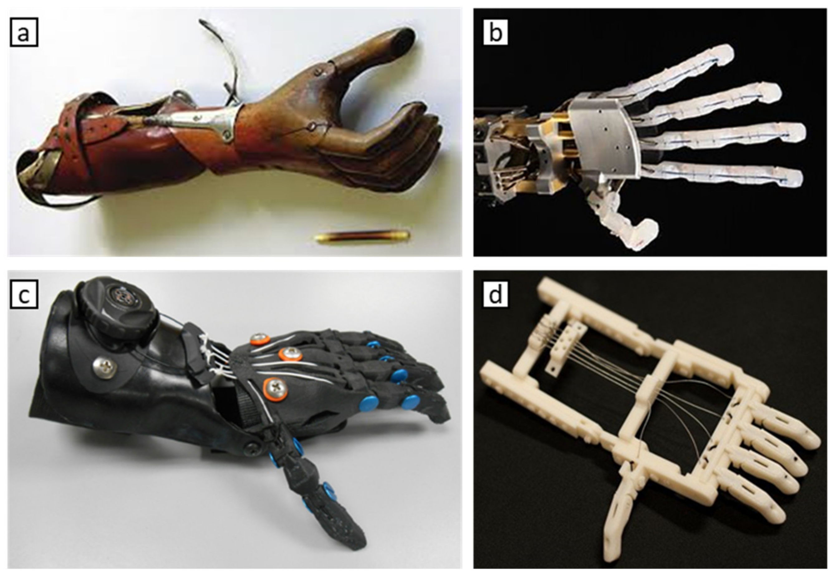
Figure 1 shows some existing prostheses.
Among the factors that lead to disability, amputation stands out because it is one of the oldest therapeutic resources of medicine and is characterized by surgical or traumatic removal, total or partial, of a limb or limb segment of the human body. Limb amputations, especially the hand, usually occur at an active age as a result of traumatic and physical causes, work-related thermal injuries, or due to injuries caused as a result of military combat. In addition, they may also occur for a variety of other reasons, the most common being congenital deficiencies, vascular disease, diabetes, cancer, or infections after injury [
6,
7,
8,
9,
10]. The loss of a limb, or part of it, in addition to reducing at first the productive capacity of the patient, can also trigger psychological and emotional impacts, because individuals who go through the amputation process see themselves as part of a special group, having difficulties with social participation focused on daily life, due to the feeling of disability, loss of independence, absence from work, pain due to surgical wound, among others. Thus, triggering factors that contribute to the emergence of psychological disorders such as depression and anxiety [
11,
12,
13]. One of the major goals of rehabilitation is to physically reintegrate an individual into their new reality, that is, in their new body state, preparing for the use of external devices such as, for example, the use of prostheses enabling greater use of its features and potentials by the user. Since an amputated or disabled person may experience difficulties during their daily lives, rehabilitation engineering becomes an important tool for persons with disabilities. Thus, favoring the interface of use and adaptation between user and orthopedic device [
14,
15]. Within this context, the main objective of this project is the development of human hand prosthesis mechanics made through additive manufacturing (AM), since, as custom hand prostheses, it has low level of customization, incorrect use, high production cost, as well as requiring constant maintenance and repairs, or how to become financially and geographically inaccessible to most people who have removed limbs.
Although the manufacture of prostheses using AM techniques is efficient in terms of use and comfort, preliminary tests are necessary to ensure the mechanical functionality of the device, especially in the clamp movement to grab objects. The biggest challenge is to establish the non-deformation of the prosthesis surface when holding and pressing massive objects. It has already been observed in previous studies, that the use of solid clamps manufactured by MA present adequate stiffness, supporting even pneumatic movements to actuate lifting jaws, as well as the precision to grasp sensitive objects and of different geometries [
16,
17].
Currently with the development of technologies such as AM and the creation of new plastic materials, mainly because they are easy-to-form materials, has led to wide customization possibilities and relatively low cost. Several studies have been and are being developed in the search for the construction of hand prostheses that are increasingly versatile, with electronic, electrical, and mechanical mechanisms, seeking to meet different levels and types of amputations of arm and hands, such as transmetacarpiana, metacarpophalangeal disarticulation, wrist disarticulation, phalangeal disarticulation, among others, arising from different causes, and in cases where the prosthesis, through the use of conventional prostheses, has difficulties in meeting the user’s needs. Therefore, it is through AM that the three-dimensional impression appears as a relevant alternative in seeking to meet the needs of an orthopedic patient, the wide aesthetic options used being available by the selection of different cores generating high degree of customization through textures and designs, weight reduction, and cost, allowing the development of a functional and personalized prosthesis available to the patient.
2. Methodology
For this work, four methodological steps were defined, as follows: (1) material characterization; (2) development and design of the virtual device model; (3) execution of computational simulations through Finite Element (FE study in the device; (4) printing and construction of the mechanical hand prosthesis through AM.
2.1. Material
The material studied was PETG (Polyethylene Glycol Terephthalate), obtained in filament form with 1.75 ± 0.5 mm in diameter, a material currently considered on the market as one of the filament types. High strength, hardness, non-brittle, has chemical resistance and neutral processing odor designed for FDM type 3D printers [
15,
18,
19].
2.2. Equipment
For the printing of Proof Bodies (PB) the printer used was the Sethi 3D of national manufacture, with the capacity to print objects with maximum dimensions of 220 mm in width (x), 210 in depth (y), and 200 mm in height (z), with nozzle diameter of 0.4 mm, filament diameter of 1.75 mm, with power consumption of approximately 0.2 kW/h, with working temperature of up to 260 °C in the nozzle, 110 °C of table heating, and power of 700 W [
20].
The experimental procedures of the tensile test were performed at the Laboratory of Strength of Materials of the Pontifical Catholic University of Minas Gerais (PUC-MG). For the experimental test, a Universal Testing Machine model 23-200 Series 23 EMIC was used with a maximum displacement speed of up to 500 mm/min with load cell with maximum capacity of 200 kN. The equipped machine is factory calibrated according to ABNT NM ISO 7500-1. The device of the machine is controlled by the Software Tesc version 3.04. In the test the displacement rate used was that defined by ASTM D638-14 being equal to 5 mm/min. Initially, an initial test was performed at 5 PB of consumption with the same rate of 5 mm/min for making a prior analysis of the equipment. The deformation of the Test Body (TB) was measured by means of a strain gauge to fix the equipment itself.
In order to evaluate the fractured region of the PETG samples with different levels of filling, from the five tests performed for each group samples with infills of 15%, 25%, 50%, 75%, and 100% were selected, one TB ruptured. For this, the samples were examined by the Jeol Electronic Scanning Microscope model JSM-IT300 with a program used to generate IT300 images. To generate the chemical analysis the gold metallizer Denton Vacuum model Desk V was used, of the Advanced Microscopy Laboratory of the Mechanical Engineering Department of PUC-MG.
2.3. Normalization
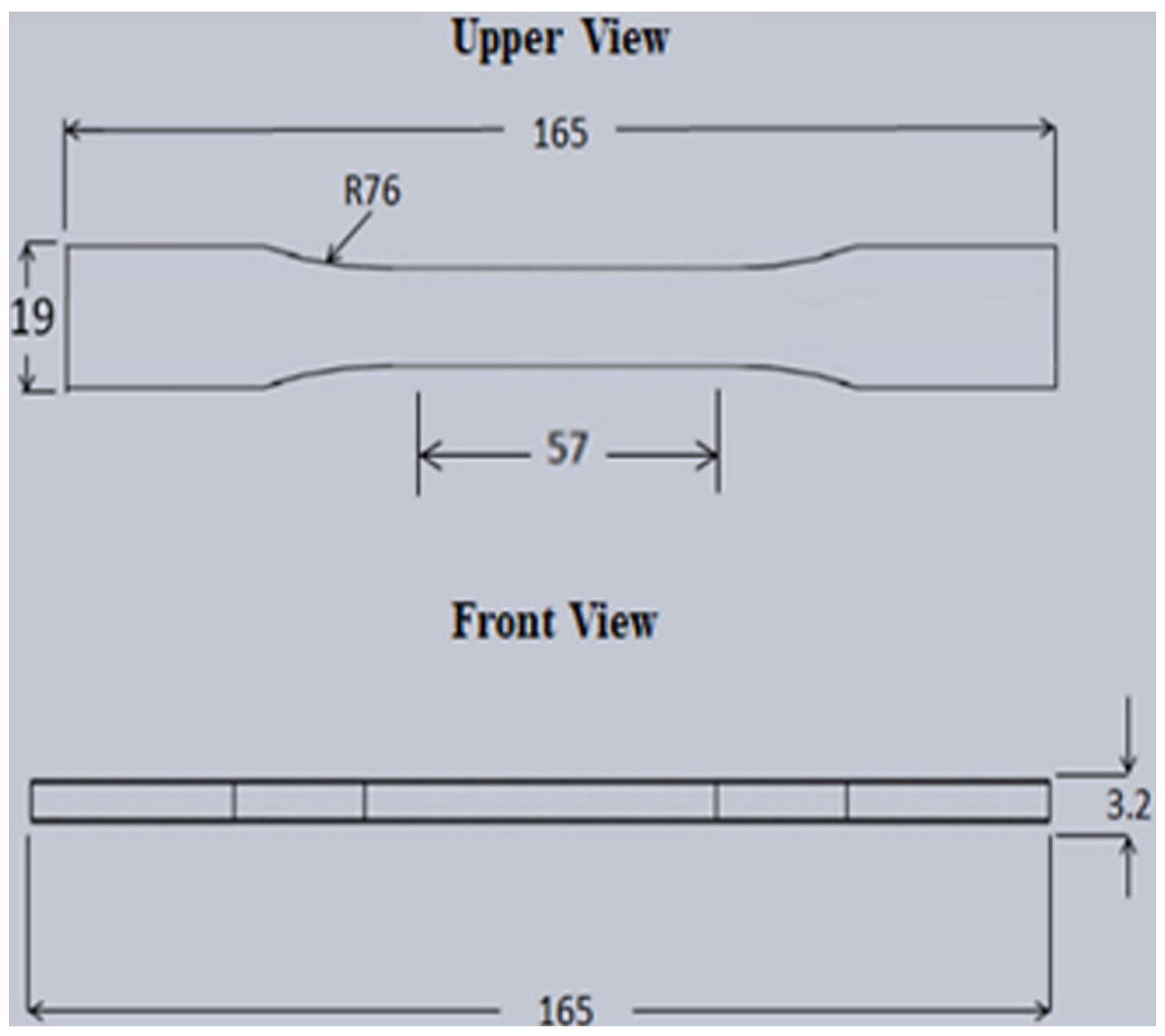
In order to manufacture and evaluate the material used for three-dimensional printing, ASTM (American Society for Testing and Materials) standards were used and ASTM D638 (Standard Test Method for Tensile Properties of Plastics) was used for the manufacture of PB (
Figure 2). The dimensions of the standardized test samples for the traction test are available in the referred standard, besides the methodological recommendation for the execution of the traction test. For the manufacture of PB, the dimensions of sample type I were considered [
21].
To design the TB design, from the values provided by ASTM D638 [
19] a Computer-Aided Design (CAD) software called Inventor Professional version 2020 was used, available from the American Company Autodesk.
The PB printing was done according to ASTM 52921 [
22] which includes terms and nomenclatures associated with systems, coordinates, and test methodologies for AM technologies establishing requirements for validation of the printing process, illustrating the location and orientation of the parts through the construction plans that can be followed during the three-dimensional printing process.
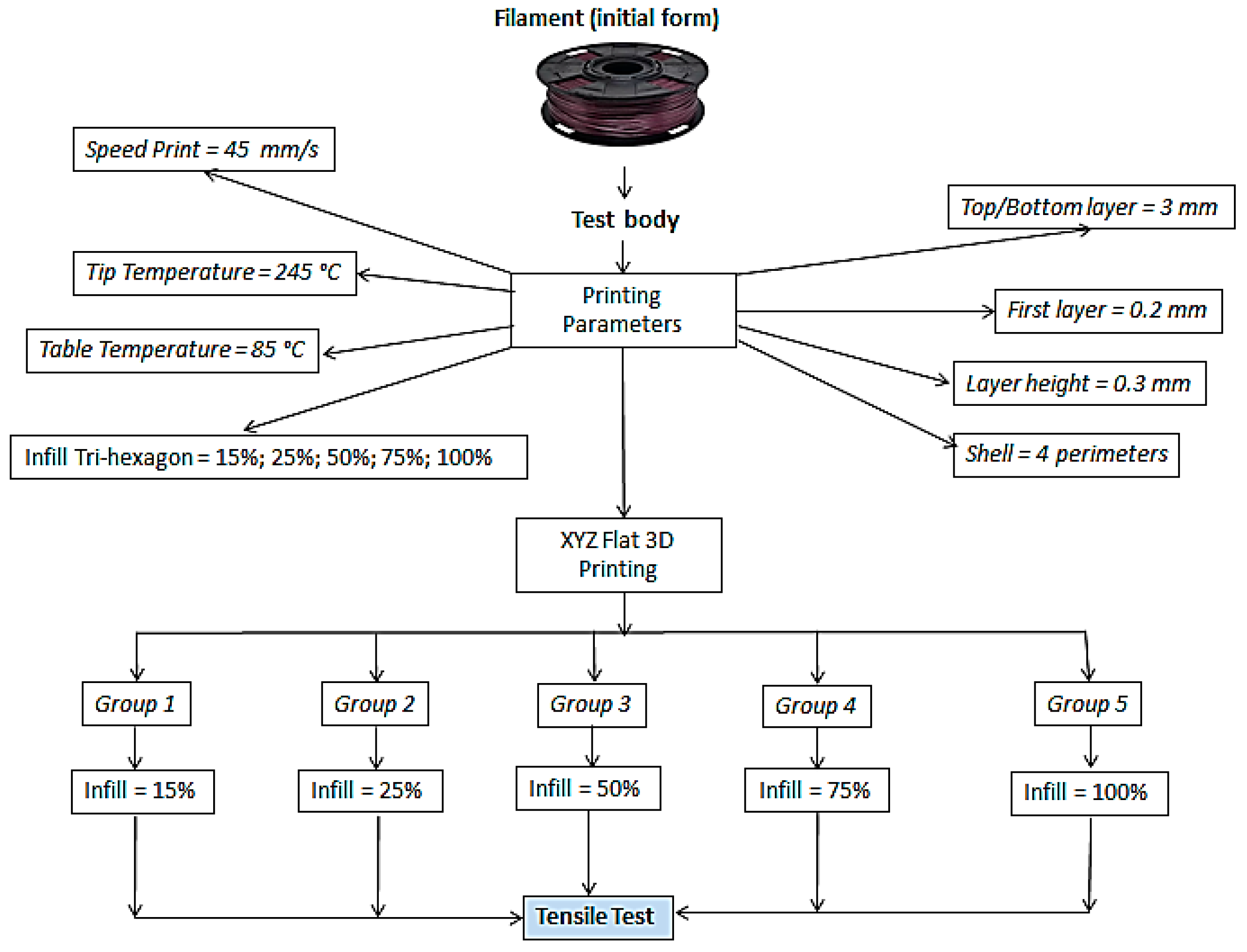
2.4. Printing Parameters
Regarding the manufacture of parts using 3D printing, since the type of material to be used in the three-dimensional printing process was defined, it is extremely important to define the main working parameters, defining the type of internal filling (infill) and density, in order to reduce printing time and material consumption. All printing parameters are shown in
Table 1.
The construction plan used for the PB manufacturing was the XYZ plan, represented in
Figure 3 below. Regarding the references of XYZ and YXZ print directions, better mechanical resistance and, at the end of the print, good dimensional precision in the printed body were achieved with FDM technology [
23,
24,
25].
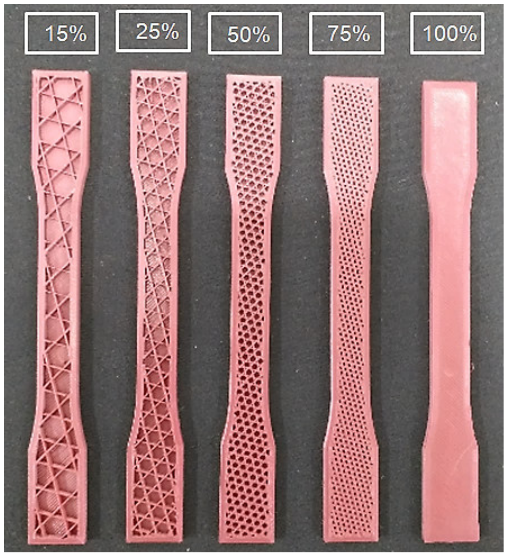
For the manufacture of PB and execution of the tensile test of this work, it was considered as a controlled parameter the density of infill in Tri-Hexagonal format, obtained by Cura Ultimaker software version 3.6.0. Since, this type of infill is considered as one of the fill patterns that gives greater mechanical resistance to the FDM technology printed part [
15,
19,
26,
27,
28].
Figure 3 shows a photo of the internal fill pattern for 15%, 25%, 50%, 75%, and 100% infill, respectively. As seen, the inner geometry is geometrically as defined by the software.
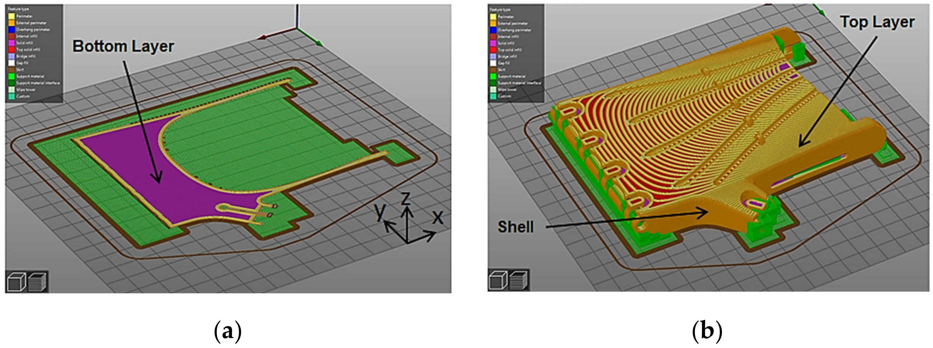
For the printing of PB, the following parameters were considered as fixed parameters: (1) shell: factor responsible for the outer “wall / shell” layer, directly influences the lateral protection and aesthetic aspect of the printed part; (2) top layer: refers to the upper closure layers aiming to make the top of the pieces, being responsible for the top closure of the piece; (3) bottom layer: is the parameter responsible for the lower closing layers, characterized by being the first printing layers giving support and protection at the base of the part; (4) speed: parameter related to printing time and adhesion between layers; (5) temperature: responsible for extruding the 3D print filament [
15,
19,
24,
29,
30].
Figure 4 illustrates some of the fixed parameters for this work.
2.5. Experimental Test
For a better understanding of the methodology for performing the tensile test,
Figure 5 shows a brief flowchart aiming to illustrate in general the methodological steps of analysis through the tensile test.
Thus, the material properties estimated in this experiment are (1) maximum stress (tensile strength), i.e., the maximum stress that the material can withstand when stretched or pulled without showing any trace of internal or external fracture in the body proof; (2) flow limit or stress (0.2%), point where the flow phenomenon begins, plastic strain starts, i.e., start of permanent TB strain; (3) elasticity modulus or Young’s modulus, mechanical property that measures the stiffness of a solid material, in the higher the modulus of elasticity, the less elastic deformation resulting from the application of a given stress; and (4) elongation at break [
31].
From the use of the initial form of the PETG Filament and after defining the printing parameters, a total of 25 PB were subdivided into five groups, with quintuples with 15%, 25%, 50%, 75%, and 100% infill.
2.6. D Development of The Hand Prosthesis
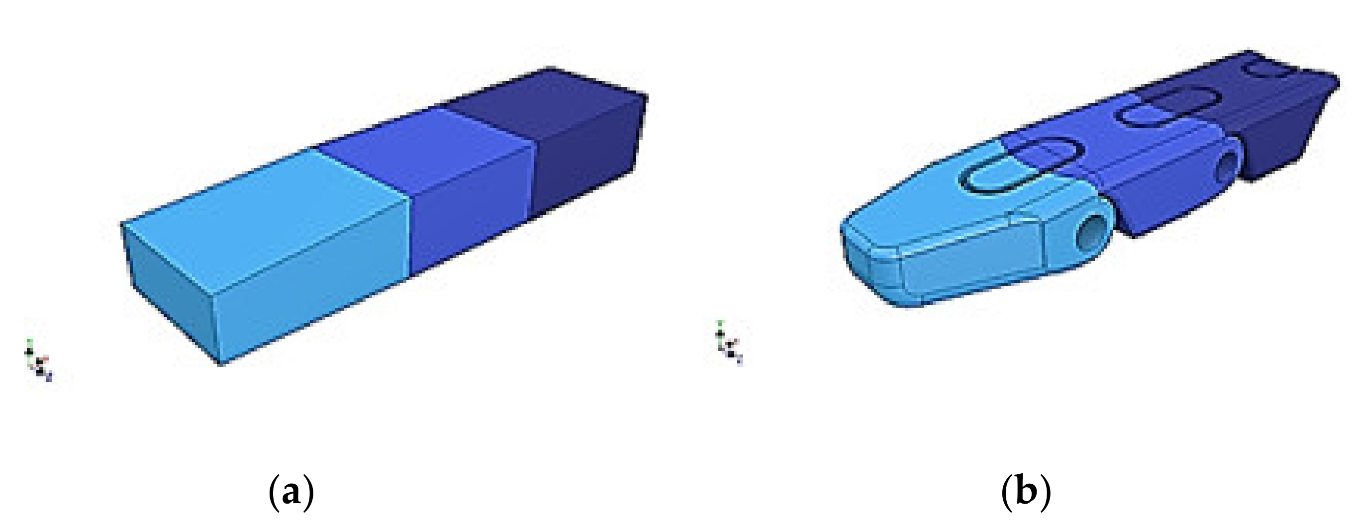
For the development of the hand prosthesis, similar modeling patterns were used to design a geometry close to a human hand, especially in relation to surface measurements and contours. A priori, the constituent parts of the device were constructed based on simple (rectangular) geometries and later remodeled according to the mobility needs for flexion movement and grip rotation.
For the development of the a priori phalanges, the fingers were constructed using a rectangular geometry as a base, and later remodeled according to the physical dimensions of the phalanges (
Figure 6), resulting in the execution of flexion and rotation movements for the gripping movement.
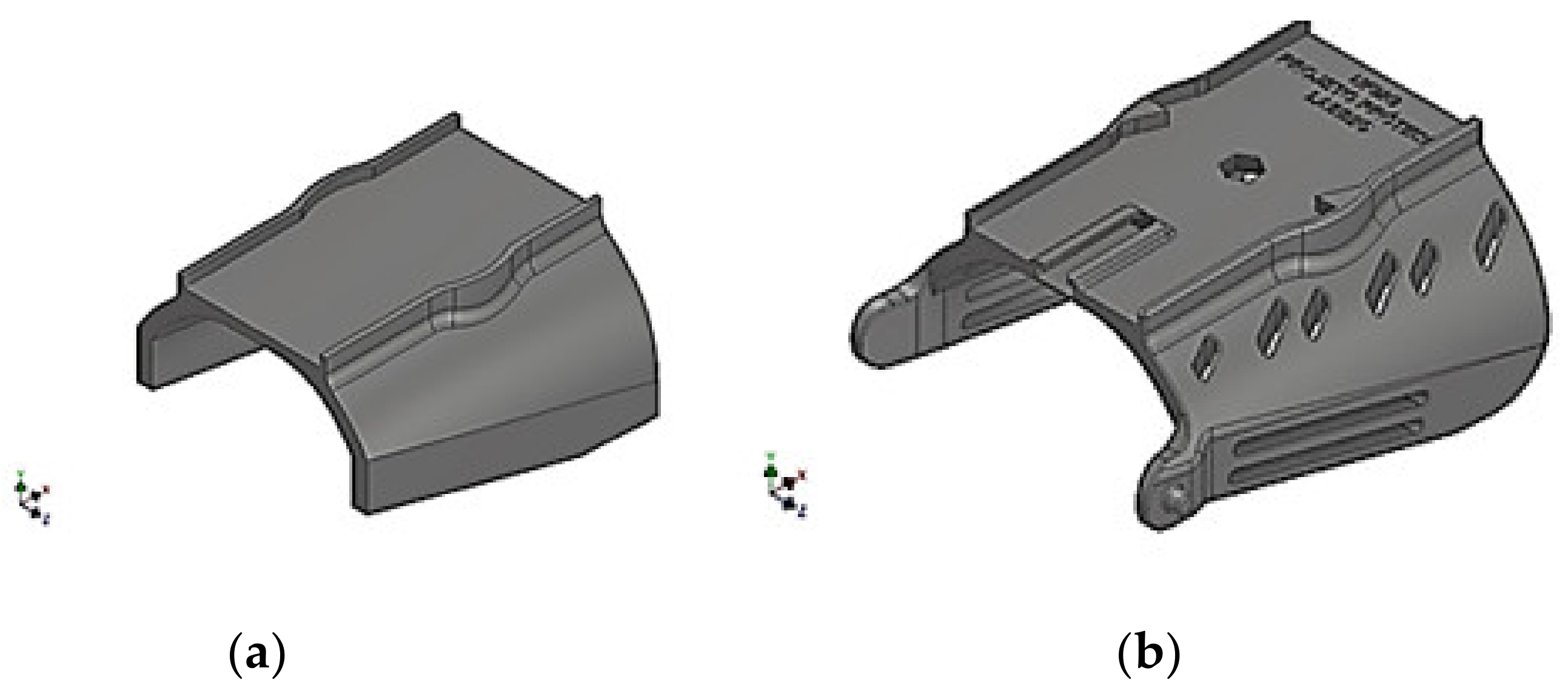
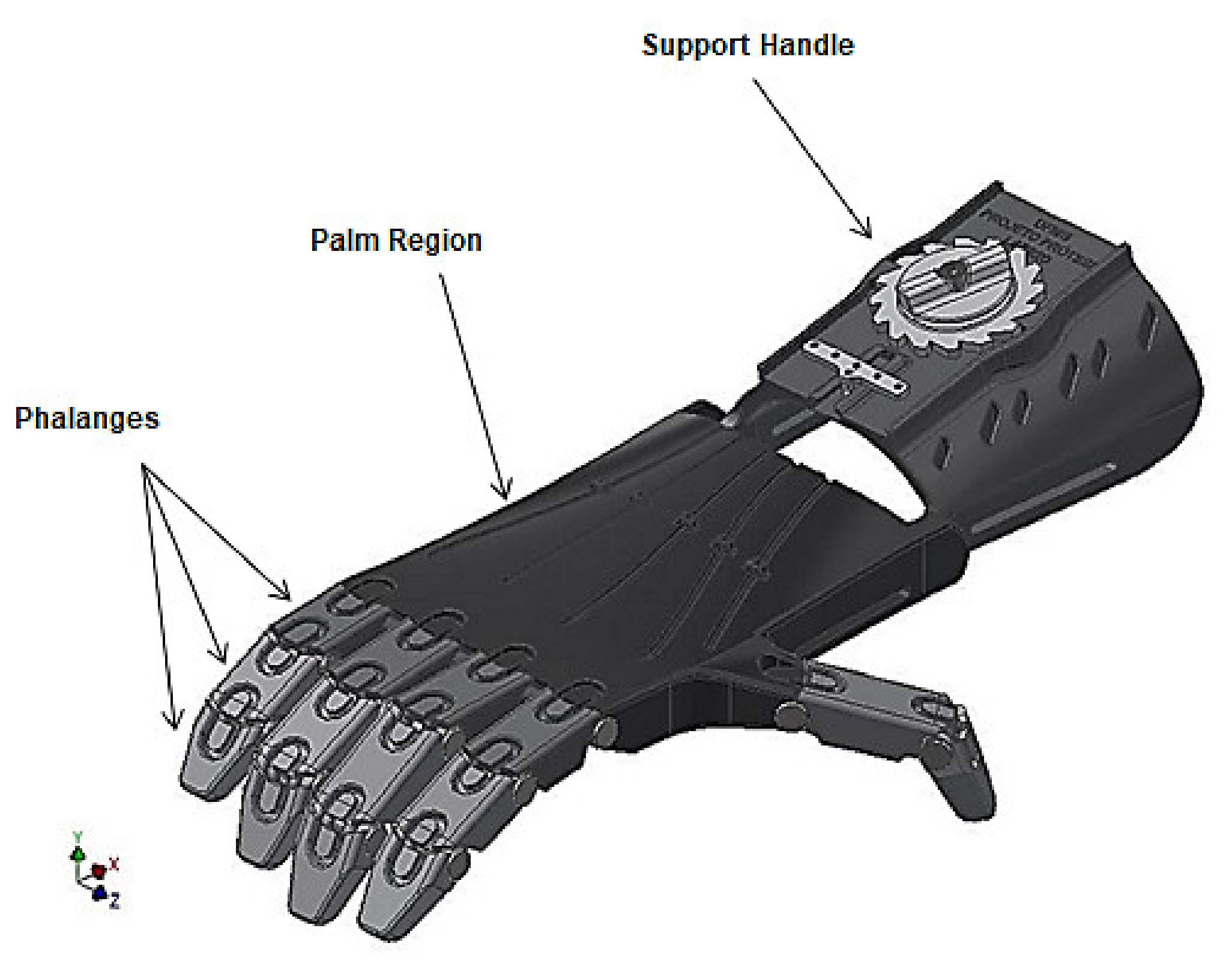
For the development of the palmar region and wrist support, some software modeling parameters were better explored for the adaptation and ergonomics of the region responsible for stabilizing the prosthesis user stump. Thus, starting from a simple geometry, the use of surfaces was employed in order to make the piece more organic, visually and anatomically, supported by splines (adaptive curves) for better modeling compliance, resulting in the geometry shown in
Figure 7 and
Figure 8.
2.7. Mechanical Feasibility Study
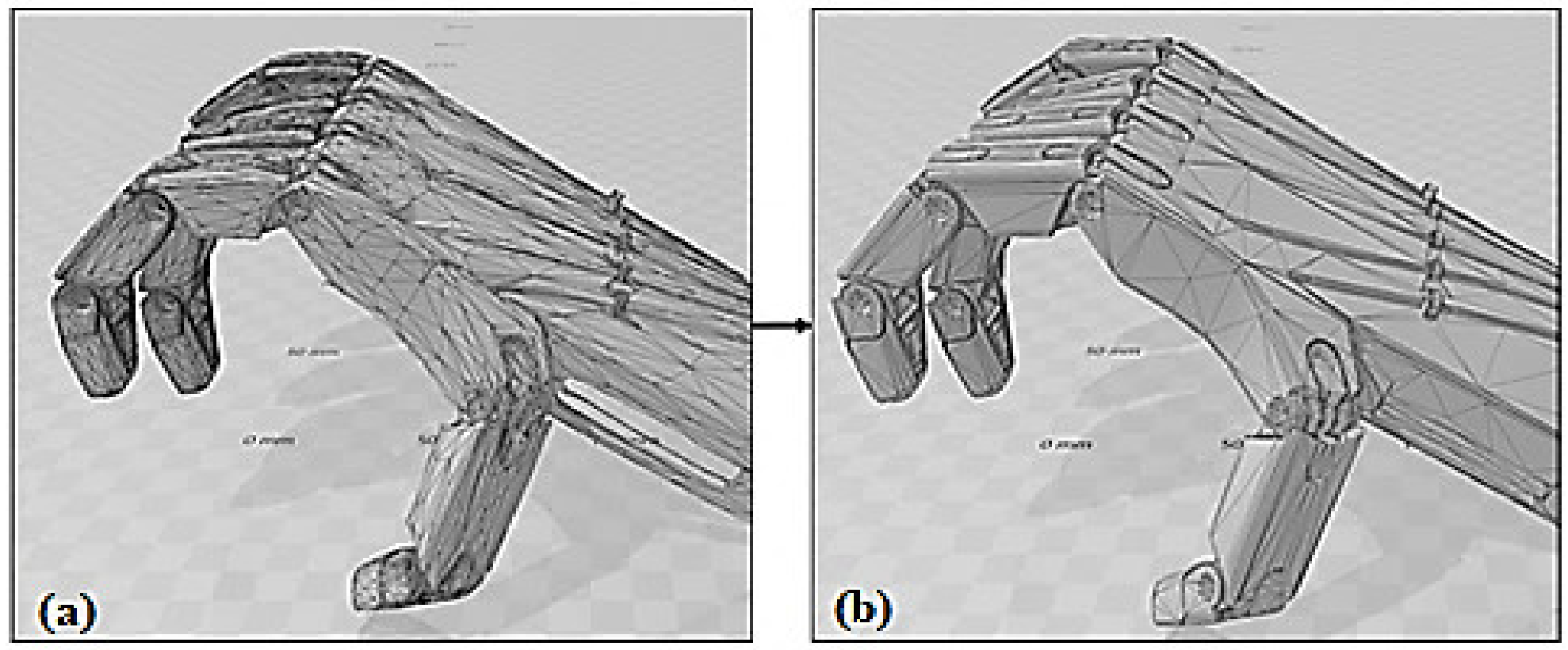
In agreement with the objectives proposed by this work, the computational simulation of stative stresses by finite element methods was performed to assess the mechanical responses of the prosthesis when subjected to compression forces when taking an object. To perform the simulations it was necessary to perform three main steps, namely: (1) the reduction and adaptation of the prosthesis model to the mesh of the object; (2) the definition of the prosthetic component materials; (3) the definition of the fixing constants of the acting forces and the definition of the acting forces on the object.
Step 1: This step consists of reducing the mesh, that is, the mesh complexity of the original prosthesis from model point cloud reduction methodologies in order to allow the mesh formation work by the study of finite elements. The model was reduced by 66.12% from an original count of 159,372 faces to 54,000 faces. The example of face reduction can be seen in
Figure 9.
Step 2: For the study, the 25% filled print configuration PETG material was used, mounting screws made of nickel-plated steel to join the prosthetic device phalanges and 0.70 mm diameter nylon line. The nylon material was chosen for the prosthesis activation line due to its resistance and elasticity characteristics [
32].
Figure 10 demonstrates the material arrangement used according to the described parts.
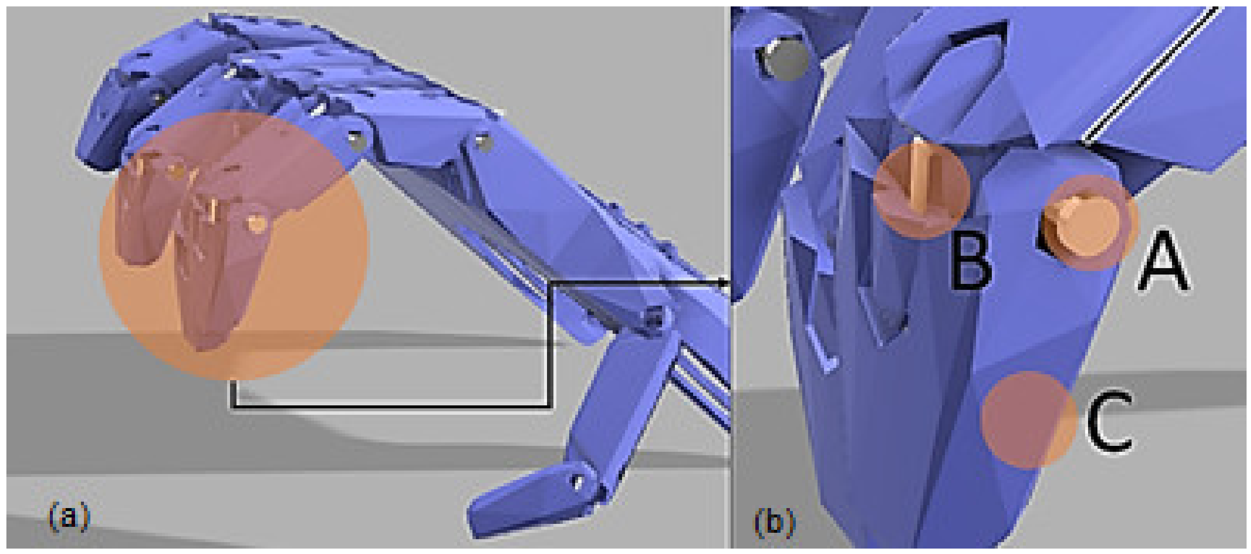
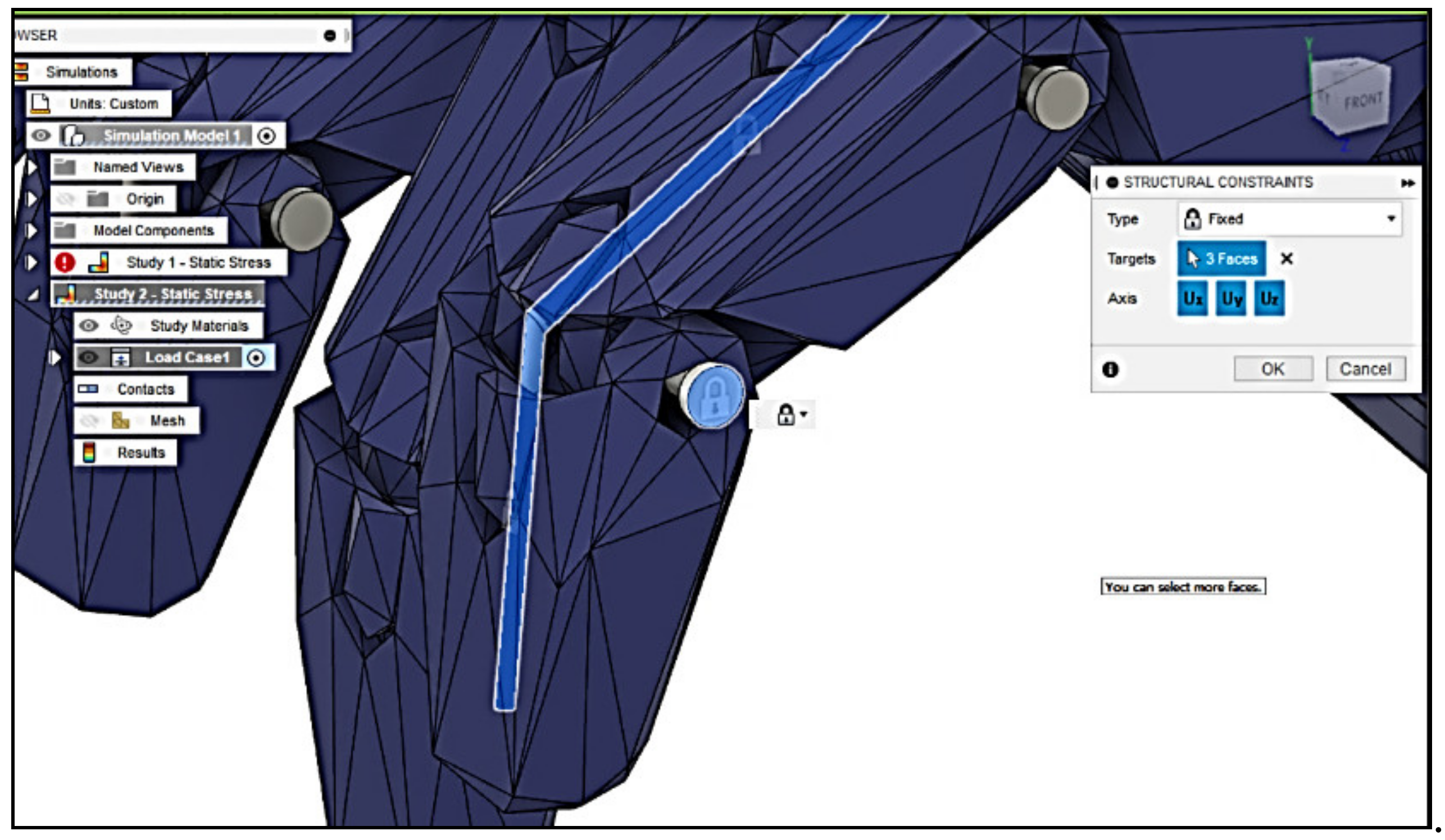
Step 3: For closer proximity to the practical reality of using the prosthesis, the fixation constants were allocated at the nylon line joints between the phalanges and over the nickel-plated steel pivot pins, as shown in
Figure 11 below.
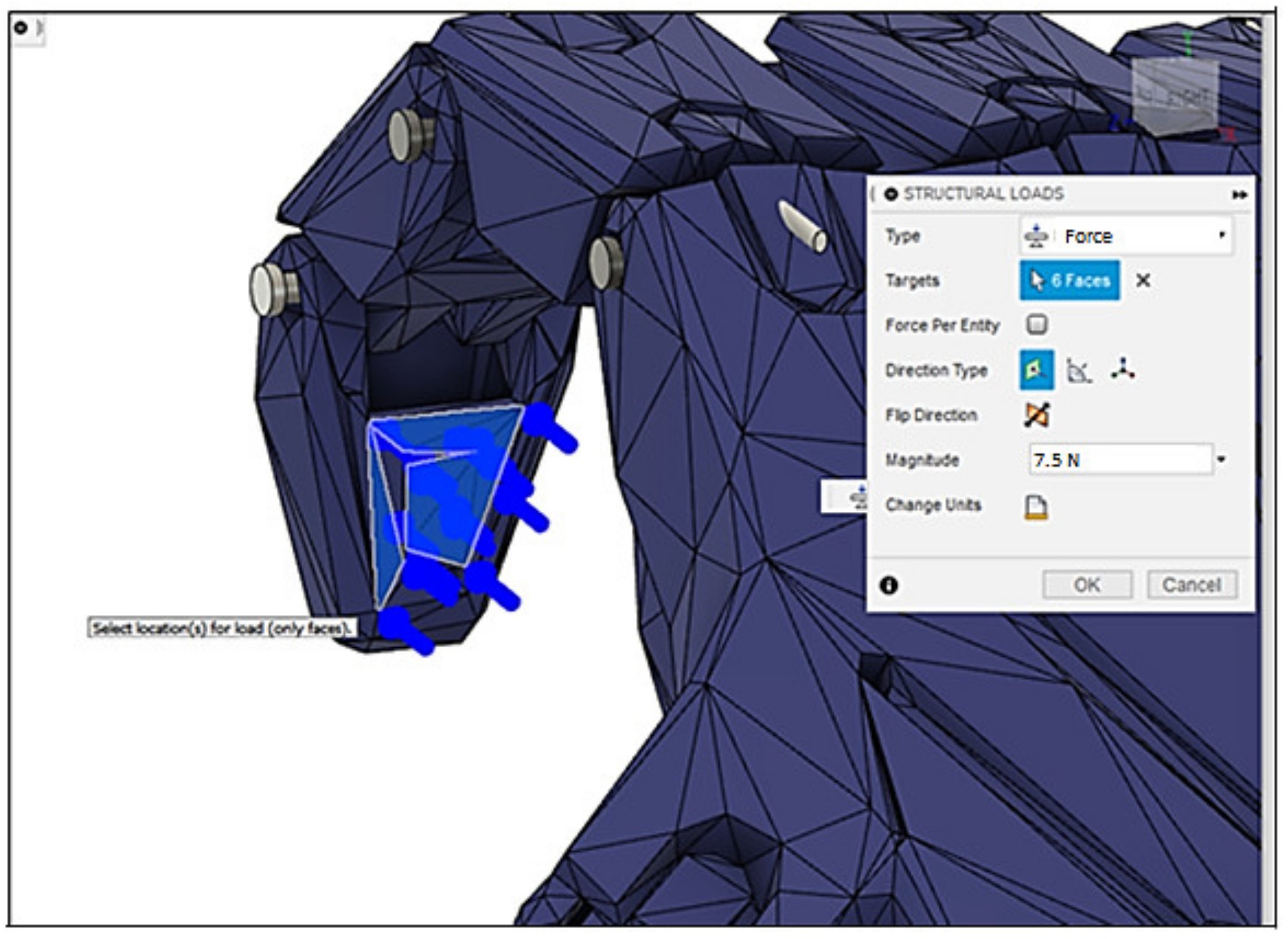
The acting forces on the object were allocated at the ends of the 7.5 Newton modulus phalanges, following orientation [
19,
20,
25] as shown in
Figure 12.
3. Results and Discussion
3.1. Specimens Measurements
Through the use of a measuring instrument called the micrometer with milesimal resolution (0.001 mm) of the brand DIGIMESS, the dimensions of the useful region of the printed PB were collected, with the purpose of verifying if they were within the defined dimensions for the width and thickness in the useful region as established by [
21]. The used width was 13 ± 0.5 mm and the thickness was 3.2 ± 0.4 mm. After collecting the five measurements in each direction, thickness and width were measured in the useful region. The measurement results and their respective averages and deviations are in accordance with the dimensions proposed by the standard.
3.2. Tensile Tests
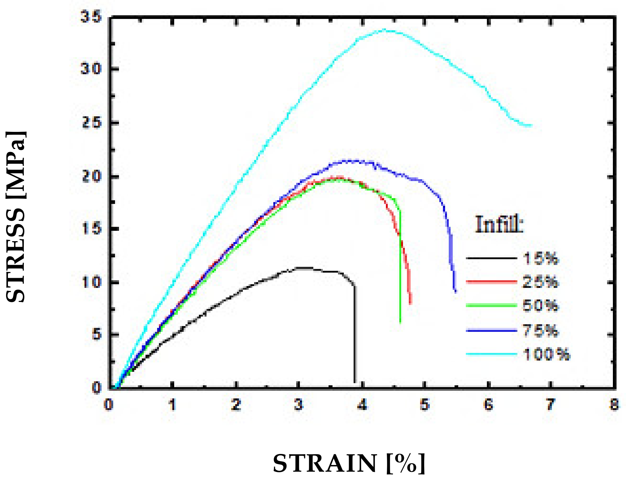
Of the five tests performed for each group of 15%, 25%, 50%, 75%, and 100% infill samples,
Figure 13 shows the results of the samples whose maximum stress values obtained in the assays were closer to the mean of the corresponding group.
Table 2 presents the synthesized results of the mechanical properties obtained through the tensile tests performed.
From the results presented, it is possible to perceive a positive correlation between the internal fill level of the PETG samples and their mechanical properties, increases in relative elongation, yield strength, tensile strength, and stiffness being observed. Importantly, the stiffness values obtained by the slope of the stress–strain curve in the elastic regime, for the present case, are not directly related to the elastic modulus of PETG (estimated at approximately 1 GPa in printed samples) due to the variation in the patterns filler employed when printing each sample group.
The observed values for yield strength and tensile strength are also a reflection of the internal structure generated in each sample group. Higher fill patterns have a higher effective cross-section and, consequently, higher tensile strength. The higher level of fill gives the samples a greater capacity for absorbing deformation energy, which can be seen by the increased tensile strength and maximum elongation.
3.3. Scanning Electron Microscopy
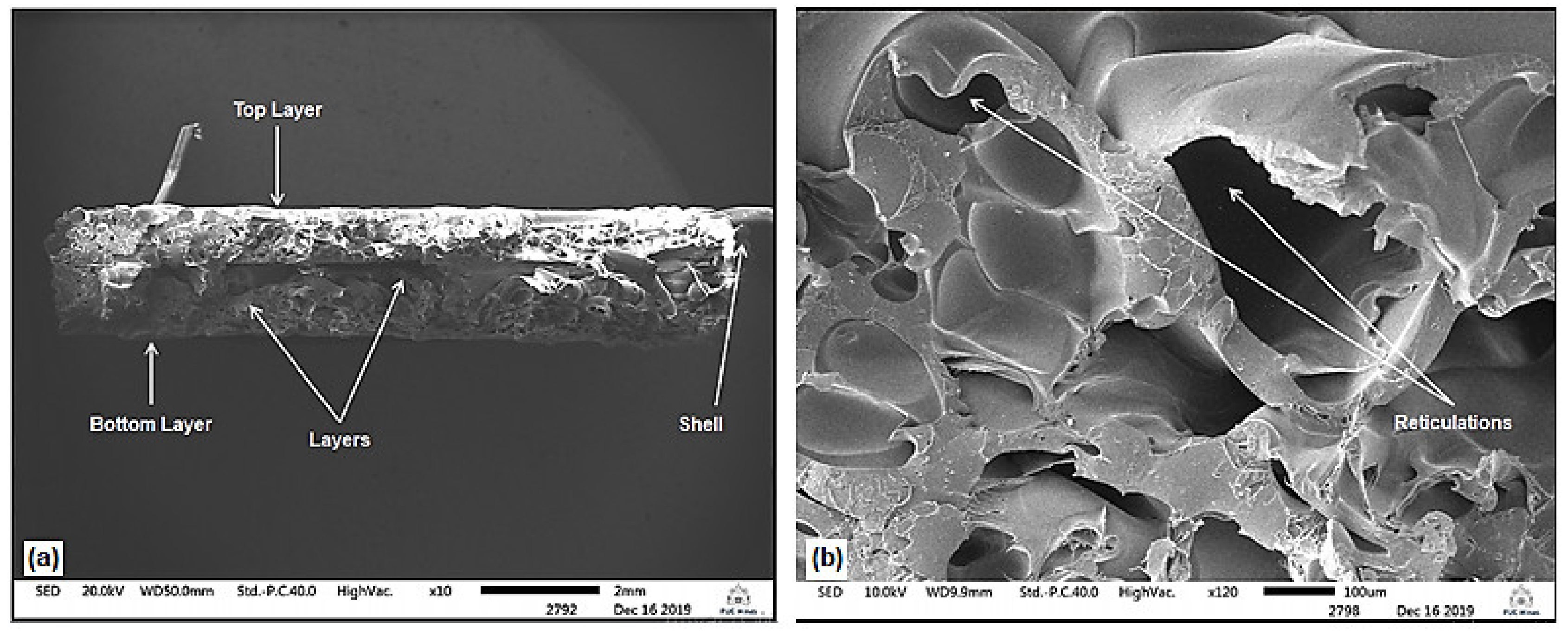
The first analysis of the ruptured cross-section of the samples after the tensile test is made is that for the different printing conditions there are smooth layer displacements regarding the material deposition. It is possible to notice in each of the individually selected PB of the five assays performed for samples with infills of 15%, 25%, 50%, 75%, and 100%, small displacements in the lines referring to the inner fill and shells after PB rupture, as shown in
Figure 14 for 15% and 25% of infill. Another difference is the final rupture region. For the samples with the highest percentage of infill this region is gently offset from the central region of the cross section. This differentiation of the final rupture region between the samples, besides being caused by the uniaxial load applied by the tensile testing equipment, may also be caused by the different internal fill percentages.
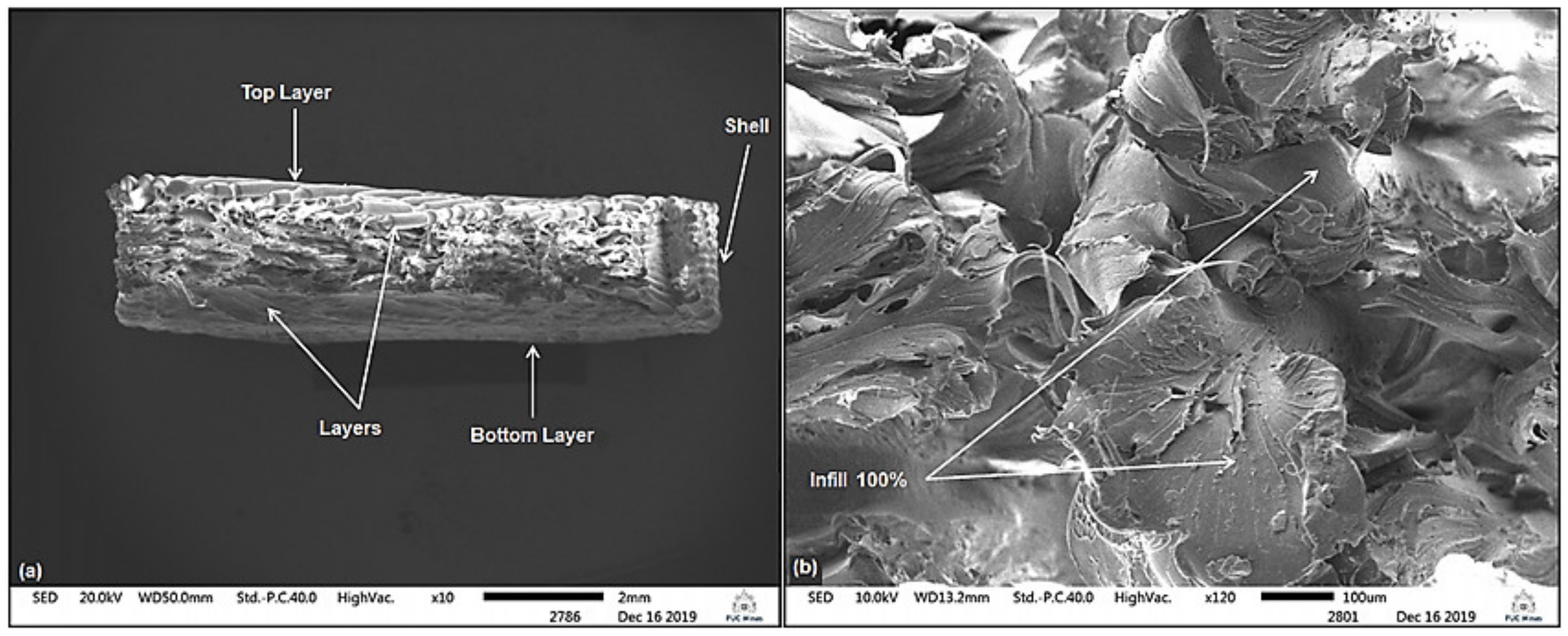
Moreover, it is possible to notice also, in the microstructure images, the internal lattices varying according to their concentrations. This is due to its internal fill density. Furthermore, it is possible to verify through the generated images the displacement of the lattices that constitute the internal region of the cross section, that is, due to the plastic deformation (permanent deformations) generated in the structure as a result of the axial load value applied by the test machine, as shown in
Figure 14,
Figure 15 and
Figure 16 for 15%, 25%, and 100% of infill.
Figure 16 shows the absence of reticulations because for infill equal to 100% fill the sample is printed as a fully solid part.
3.4. CAD Device Development
Using rectangular geometric bases and pattern-based remodeling based on anatomical geometries with dimensions close to that of an adult human male hand, it was possible to design the 3D CAD mechanical hand prosthesis model (
Figure 17) as shown below.
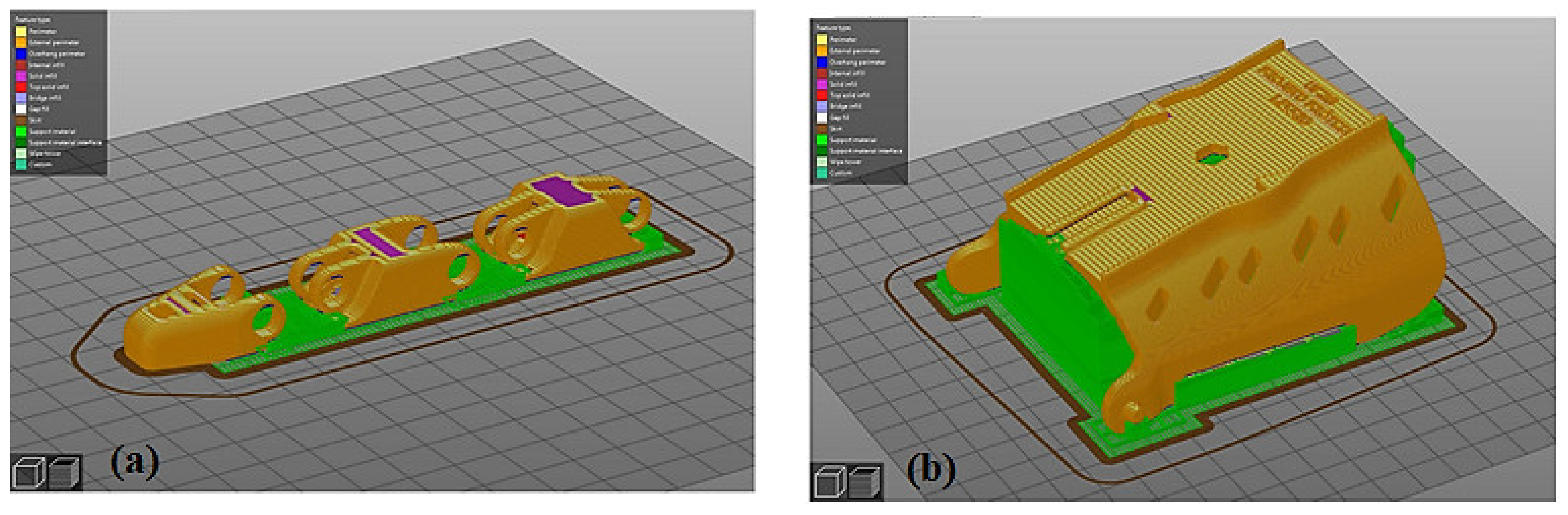
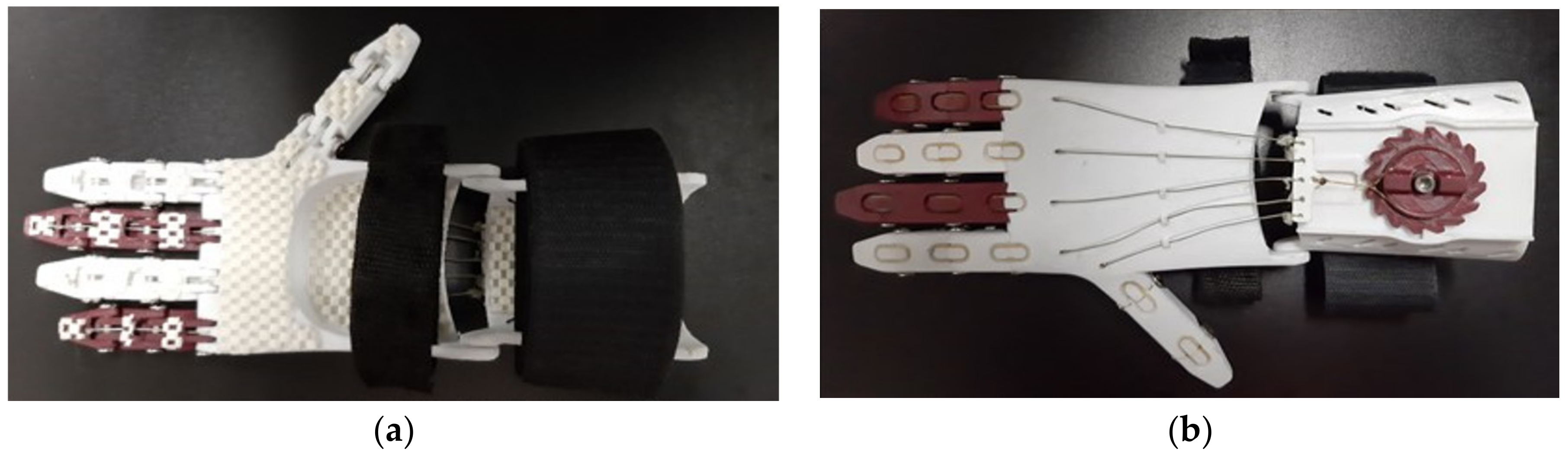
3.5. Device Printing
The prosthetic device developed and constructed presents an anthropomorphic appearance, employing the tenodesis effect to create the movement made through the wrist flexion movement and passive digital release via elastic components. The fingers and thumb are attached to a palm component by mounting screws and the palm region hinges with a stabilizing “glove” forearm support. Active flexion movement of the wrist is achieved through a line of high non-elastic resistance, and passive extension of the fingers occurs through elastic elements such as orthodontic elastics along the back of the fingers. It was FDM type with PETG polymeric material. With the projected 3D CAD project and the printing parameters set a priori in the project, it was possible to print the device with 25% infill.
Figure 18 illustrates the process of printing some of the device’s main components through the image generated by the printing software.
Parts made using three-dimensional printing have variable dimensions, as a result of the printing plane and the geometric elements. On the other hand, the components printed in the horizontal plane [
22], gives better dimensional accuracy to the printed body [
23,
24]. That is, when printing on the XYZ plane [
22], it was allowed to have the reliable dimensionally sized prosthesis parts with low R_a roughness values not exceeding 25 µm. In the case of the prosthesis, according to reports in the literature, after being made the device can be used by the user in a functional and comfortable way.
3.6. Device Building
The constructed prosthesis (
Figure 19) took approximately 8 h to have all of its constructive polymeric components printed. For assembly and finishing the average time consumed was 3 h. The final weight of the fully assembled device was 263.90 g. The estimated cost of the device is
$60.82, which is a low cost compared to the cost of conventional prostheses, with values ranging from
$316.30 to
$1408.75 [
33,
34]. In addition, in the global market, there are upper limb prostheses with sophisticated operating systems that cost between
$25,000 and
$58,000 per unit [
25,
35,
36].
Regarding the weight achieved in the prosthesis (less than 270 g) developed in this project, it is essential for the user in the adaptation process, to have prosthetic devices that have the ability to combine mechanical strength and low weight, being extremely important factors in the rehabilitation process. Thus, having a polymeric raw material for use in the three-dimensional printing process, such as PETG, which, despite being a light input, has values for printing with 25% infill, having density of 1.27 g/cm3, yield stress of 14.19 MPa, maximum tension of 20.68 MPa, and modulus of elasticity of 552.54 MPa.
Since through significant properties the material stiffness can be evaluated through the value of its modulus of elasticity, the value of the initial strain of the plastic deformation can be evaluated by the stress or yield strength. Therefore, values that show that it is possible to use Fused Deposition Modeling printing technology regarding the manufacture of hand prostheses, giving the orthopedic device good mechanical strength and lightness.
After the prosthetic device is built, it can be placed over the region of the amputated limb, the prosthesis stabilization in the deficient region may be done through the use of Velcro stabilizers of firm padded foam (medical grade), protective stockings for the skin and tension adjustment executed by the fixed directional coupling (ratchet), so that the prosthesis can have a stable, comfortable, and functional use during the execution of daily activities. It is important to highlight that, with regard to the ratchet, once the prosthesis is placed on the patient’s amputated region, it is possible to adjust the functional movement of the prosthesis, made by traction of the risers. High resistance lines the upper surface of the prosthesis, in order to allow the clamping and gripping movements performed by the device made from the angles 20°–30° degrees of the wrist flexion movement. This calibration can be done using an instrument capable of measuring angles called a goniometer, whose capacity allows to evaluate the angulations of the phalanxes and the wrist articulation.
The operation and activation of the prosthetic device is possible, since high density orthodontic elastics are placed on the upper part of the interphalangeal regions, which allows passive extension of the finger. The flexion movement of the fingers is carried out through high resistance cords placed along the external palmar and phalangeal surface of the hand and fingers, being activated through the wrist flexion movement made at an angle between 20° and 30° degrees, resulting in a composite wrist with the ability to flex the fingers towards the palm of the hand.
Thus, with this device it is possible through the handgrip movement, to pick up and hold objects with different geometries, such as a PET bottle with a volume of water equal to 500 mL, a Fuji apple with approximately 75 mm in diameter, a cubic body with 10 mm edge, cylindrical bases of different screwdrivers or screwdrivers, a marker brush for a whiteboard 125 mm long and 15 mm wide, among other items weighing no more than 1.5 kg.
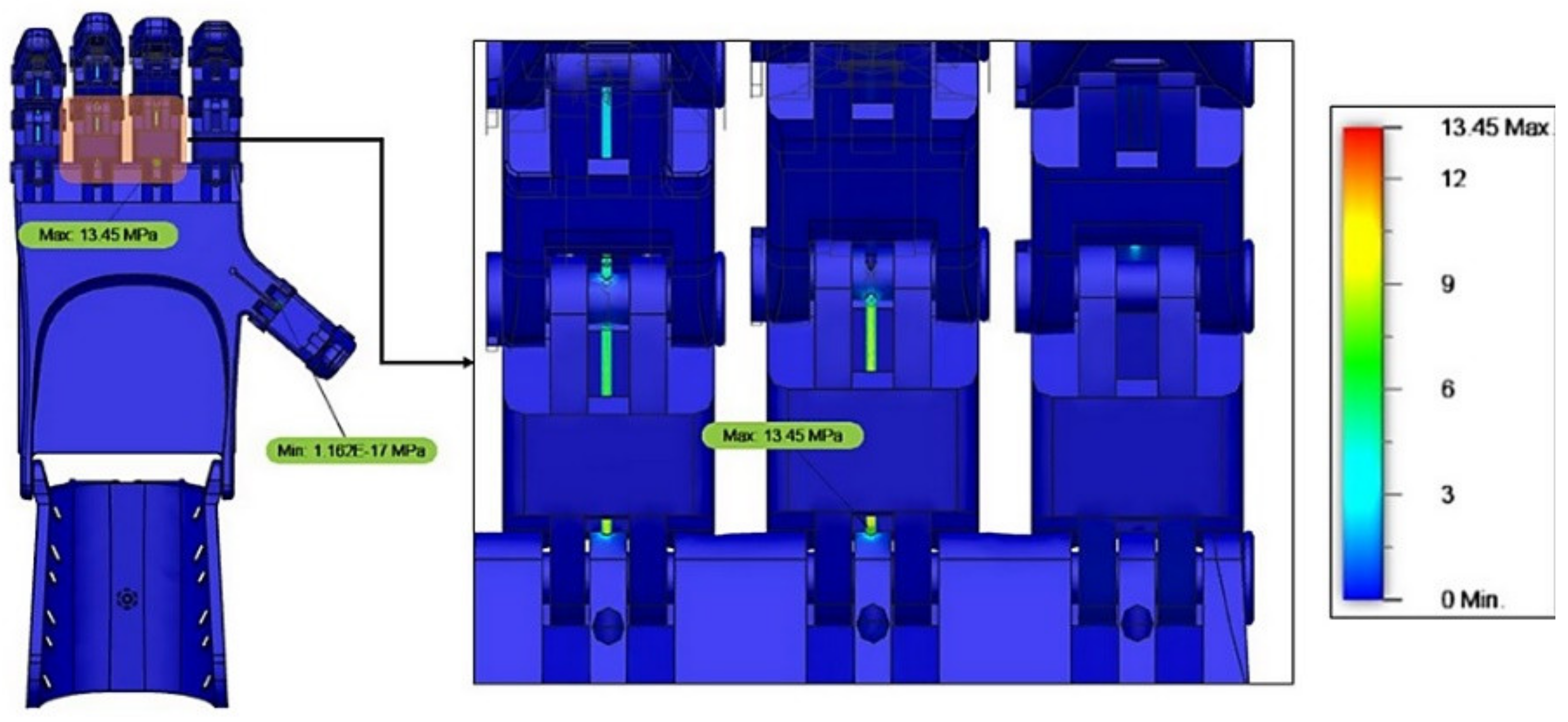
3.7. Mechanical Feasibility Study
For the development of the simulation finite element model to evaluate the stress concentration on the surface [
31,
37,
38,
39,
40], forces of 7.5 N were used in the distal region of the phalanges individually, according to the bibliographic orientation [
19,
20,
23,
25,
35,
36]. Responses to the proposed loads showed maximum stress of 13.45 MPa on the braided line near the proximal phalanges, as shown in
Figure 20.
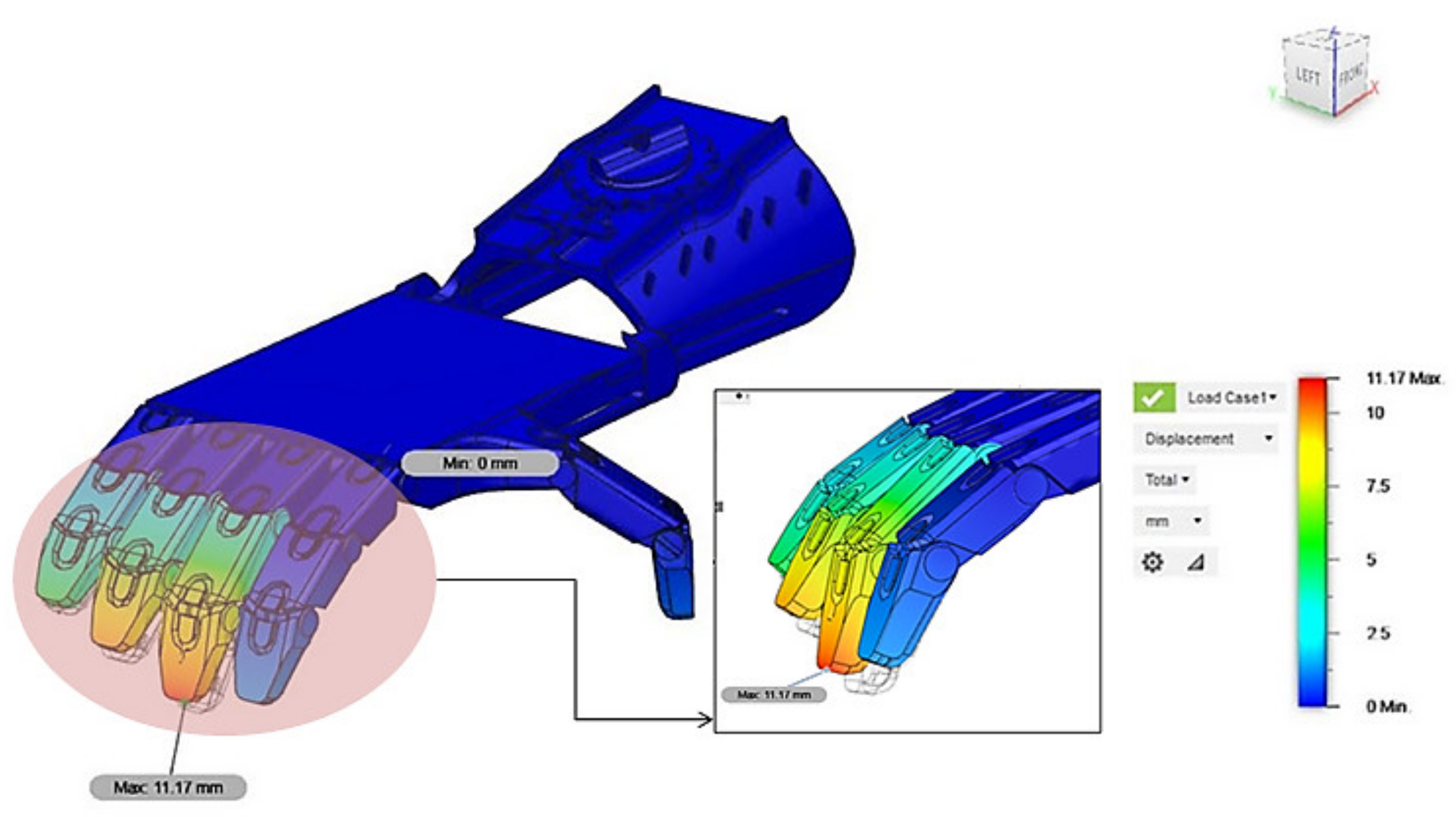
Relative surface displacement in response to loads showed a maximum observed value of 11.17 mm in the proximal region of the middle finger phalanges, as shown in
Figure 21. This is because the middle finger is farthest from the fulcrum point, or that is, the torque in this finger is higher than in the other fingers. The generated color map shows that the tensions in the index finger (region in blue tint) indicate that the tensile forces in this finger were not as significant as in the other fingers.
4. Conclusions
In the proposal of this work one can observe fundamental factors that influence the 3D printing process, mainly in relation to its printing parameters and mechanical properties.
Maximum stress, yield stress, modulus of elasticity, elongation, and hardness are the prominent properties that should be considered when choosing the polymeric FDM printing material as they are directly related to the chemical composition. Microstructural characteristics and the ability of the printed product to obtain good mechanical strength at the end of three-dimensional printing, which in the case of prostheses is essential to combine the low weight with the high mechanical strength of the device.
Regarding the finite element simulation, gauging the mechanical functionality of the device through static load simulations, using the gripping force of 7.5 N in the distal region of the phalanges, the proposed load responses present a maximum stress of 13.45 MPa on the plotted line. In the palmar and phalangeal region, a maximum value of 11.17 mm was found for the relative displacement of the surface in the proximal region of the middle finger phalanges. According to the simulation the surface of the device showed no plastic deformations and/or ruptures. Additionally, according to finite element studies, nylon thread was used for stress support simulation up to 31.19 N until its rupture.
The file with the prosthesis model developed in conjunction with the 25% infill printed additive manufacturing process and the Tri-hexagonal internal fill geometry after the 3D printing process showed good dimensional accuracy and good surface finish. It was a low weight device (263.90 g). The device features low assembly complexity and rapid construction.

 ,
, 


