Article

Integral Aircraft Wing Panels with Penetration Cracks: The Influence of Structural Parameters on the Stress Intensity Factor

1
College of Mechanical and Electrical Engineering, Central South University, Changsha 410083, China
2
Light Alloy Research Institute, Central South University, Changsha 410083, China
3
State Key Laboratory of High Performance Complex Manufacturing, Central South University, Changsha 410083, China
4
Avic The First Aircraft Institute, Xi’an 710000, China
5
School of Astronautics, Northwestern Polytechnical University, Xi’an 710072, China
*
Author to whom correspondence should be addressed.
Appl. Sci. 2020, 10(12), 4142; https://doi.org/10.3390/app10124142
Submission received: 7 May 2020 / Revised: 12 June 2020 / Accepted: 13 June 2020 / Published: 16 June 2020
(This article belongs to the Section Mechanical Engineering)

Abstract

:
The finite element model of integral wing panels with central penetration cracks under bending load was established, and the crack propagation process of the aircraft panel was simulated. The stress intensity factor (SIF) of the crack tip during crack propagation under varying conditions of crack length and panel structural parameters was determined. The effects of the panel structure parameters and crack size on the crack tip SIF were obtained. The regression analysis of the finite simulation element results has been performed and a regression model of SIF at the crack tip of the integral panel has been established, the determination coefficient of the regression model is 0.955.

1. Introduction

The panel is one of the main structural parts of the fuselage, wing and tail of the aircraft. Traditional aircraft panels are usually assembled from skin and internal stiffeners by riveting, screwing and welding [1]. The manufacturing and processing difficulty of the assembled panel structure is low, and the crack arrest performance is good. However, with the development of modern aircraft design, its rigidity, strength, fatigue performance, sealing performance and other aspects cannot meet the requirements of aircraft use [2]. The integral panel not only has obvious advantages in these aspects, but can also avoid defects and crack initiation caused by welding structure [3]. Therefore, in the design and manufacture of modern aircraft, the integrated design and manufacturing panel is gradually used to replace the assembled panel. The difference between the integral structure of the airframe and the assembled structure is shown in Figure 1. Replacing the traditional riveted assembly structure with the integral structure of large integrated aircraft has become a major trend of aircraft structure design, and the research on the integral structure has become an important research direction of aircraft structure design [4].
Although the performance of the integral panel is much better than that of the assembled panel, due to the lack of anti-crack components such as bolts and rivets holes, once microcracks appear, it still faces the problem of insufficient damage tolerance [5]. Therefore, the research on the fracture resistance of the whole structure with cracks has become an important part of the research on the damage tolerance of the integral structure. Huang Qiqing carried out a fatigue crack growth test on the whole ribbed panel, analyzed the basic characteristics and rules of the structure fatigue crack growth, and provided the basis for the damage tolerance evaluation and design of the whole ribbed panel [6]. Yan Xiaozhong used the finite element software ABAQUS to set up a parameterized model of cracks in the integral panel of a typical aircraft, and analyzed the changes of stress intensity factors of cracks in the boss and rib during the crack growth process and the crack arrest performance [7]. Taking the commuter aircraft as an example, J. Sedek analyzed the crack growth under the action of section by section load, and predicted the crack growth using the linear damage accumulation principle and FASTRAN delay model [8]. M. Fossati demonstrated the application of numerical methods to evaluate the behavior of the longitudinal cracked plate on the whole machined surface, introduced the different finite element methods for a single cracked plate, and proposed an “analytical cycle method for predicting crack growth and residual strength in integral structures” [9].
At the same time, many scholars have studied the repairing techniques of aircraft structural cracks based on the stress field at crack tip and damage tolerance. Boscolo M studied the performance of crack retarders bonded to integral metallic structures by a numerical simulation [10], Hoang-Ngoc C-T studied balanced single-lap bonded and hybrid (bolted/bonded) joints with flexible adhesives using finite element analysis [11], Yashi Liao studied the residual fatigue life of repair structures under different shapes, sizes, positions and stress levels [12]. Therefore, the study of the influence of structural parameters on the SIF at the crack tip can provide a basis for the structural optimization and the improvement of the fracture resistance of the integral panel.
The change of the structural parameters of the integral panel will affect its bearing capacity. Generally speaking, the structure size of the increase will improve its bearing capacity, but the internal space of the wing is limited. Thus, the weight of the wing cannot be too large, and the structural stability needs to be considered, so there are upper limit requirements on the structure size [13]. At the same time, the influence of structural parameters on the stress field is different. Therefore, the influence law of structural parameters on the stress field of crack tip can be used to optimize the structural parameters of the whole wainscot from the perspective of crack resistance performance.
In this study, the center through crack extension model of the t-shaped structure integral panel is established by using the Finite Element Method (FEM), the simulation flow of crack propagation is determined [14]. By controlling a single variable to calculate the SIF, the influence of three structural parameters of the whole panel on the crack tip SIF was analyzed. According to the results of the finite element analysis, the regression model of stress intensity factor prediction based on the structural parameters of the integral panel and the crack size is obtained [15]. The validity of the model is determined by comparing the predicted value of the regression model with the calculated value of the FEM.

2. Finite Element Model

2.1. Damage Tolerance and Stress Intensity Factor

Damage tolerance refers to the ability of a structure to resist damage caused by defects, cracks or other damages during specified unrepaired service life. In short, it refers to the initial defect in aircraft structure and the degree of defect development in use [16]. Therefore, the damage tolerance design concept involves acknowledging whether structures have initial defects before use. However, it must consider the defect or damage according to the method of design of the prescribed maintenance use during the period of growth control in a certain range. In the meantime, the structure should satisfy the requirement of the provisions of residual strength (including defect or crack structure bearing capacity) to ensure the safety and reliability of aircraft structure [17].
In order to determine a safe service life of components, it is necessary to be able to calculate the time at which the crack develops and breaks. Therefore, for damage tolerance analysis, it is necessary to provide information about the structural strength changes with the crack size and determine the crack propagation life [18]. The SIF describes the severity of the stress distribution around the crack tip. It is used as a fracture parameter to describe the crack growth in linear elastic fracture mechanics (LEFM), which is related to the size of the characteristic crack and load of the structure [19]. Only by determining the SIF correctly can the critical length and fatigue life of structural elements before failure be calculated accurately. According to the direction of load, the crack can be divided into type I crack, type II crack and type III crack. Among them, the load direction of type I crack is perpendicular to the crack surface. The loading direction of type II crack is parallel to the crack surface and perpendicular to the crack line. The load direction of the type III crack is parallel to the crack surface and crack line. M-Integral is used to calculate the stress intensity factor, and the expression of M-Integral energy is [20,21]
M ¯ ( 1 , 2 ) = Γ ( σ i j ( 1 ) u i ( 2 ) x 1 + σ i j ( 2 ) u i ( 1 ) x 1 W ( 1 , 2 ) δ 1 j ) q x j d s ,               i = 1 , 2 , 3 ; j = 1 , 2
    W ( 1 , 2 ) = σ i j ( 1 ) ε i j ( 2 ) = σ i j ( 2 ) ε i j ( 1 ) ,
where Γ is the integral loop around the crack tip; u i ( 1 ) , u i ( 2 ) is the component of the displacement vector; δ 1 j is the Kronecker delta and q is a function that is 1 at the stress intensity evaluation point and zero on the outer boundary of the domain of integration; W ( 1 , 2 ) is the strain energy density.
The form of M-integral is same as the form of interaction integral. The definition of M in terms of the crack tip field variables that can be obtained from an FEM analysis (superscript (1)) and from the theoretical expressions of KI, KII and KIII (superscript (2)).
K I = K I ( 1 ) + K I ( 2 ) ,         K I I = K I I ( 1 ) + K I I ( 2 ) ,         K I I I = K I I I ( 1 ) + K I I I ( 2 ) ,
The definition of M in terms of Ks and material properties is defined as [22]
M ( 1 , 2 ) = 2 ( 1 v 2 ) E K I ( 1 ) K I ( 2 ) + 2 ( 1 v 2 ) E K I I ( 1 ) K I I ( 2 ) + 2 ( 1 v 2 ) E K I I I ( 1 ) K I I I ( 2 ) ,
and two definitions for M-Integral are equal.
Γ ( σ i j ( 1 ) u i ( 2 ) x 1 + σ i j ( 2 ) u i ( 1 ) x 1 W ( 1 , 2 ) δ 1 j ) q x j d s A q = 2 ( 1 v 2 ) E K I ( 1 ) K I ( 2 ) + 2 ( 1 v 2 ) E K I I ( 1 ) K I I ( 2 ) + 2 ( 1 v 2 ) E K I I I ( 1 ) K I I I ( 2 ) ,
Then the stress intensity factors can be calculated according to Equation (4) in FEM analysis.

2.2. ABAQUS-FRANC3D Co-Modeling

In this paper, FEM was used to study the stress field at the crack tip. Finite element analysis software ABAQUS and crack analysis software FRANC3D were selected as simulation platforms. Among them, ABAQUS was used as modeling tool and solver, and FRANC3D was used as crack treatment tool [23].
The ABAQUS is a nonlinear finite element analysis software from Dassault SIMULIA, which is used for finite element modeling, model segmentation, and solution analysis and post-processing of stress-strain results [24]. FRANC3D is a new generation of crack analysis software developed by American FAC company, which is used for crack implantation, mesh repartition, model splicing and transformation of stress field results to fracture parameters. This joint simulation method combines the characteristics of the two software, has the advantages of free modeling and free crack addition, and can directly obtain the SIF J integral and other fracture parameters of the whole crack tip [25].
The workflow is shown in Figure 2. The specific operation steps are as follows:
  • Build the finite element model in ABAQUS, and define the corresponding model size, material properties, assembly form and grid division;
  • In ABAQUS, the model is divided into the regions to implant cracks and the complementary remaining regions;
  • In FRANC3D, the area to implant the crack is imported, and the corresponding crack is implanted at the predetermined position. The appropriate mesh refinement parameters are selected.
  • Import the splicing new model into ABAQUS, define contact properties, apply bending load and boundary conditions, create a calculation file, add necessary keywords and submit the calculation;
  • The calculation results were extracted in ABAQUS to obtain the stress-strain field of the finite element model, and the fracture parameter report of the crack tip could be obtained in FRANC3D.
The finite element model of the simplified structure of the wing integral panel is shown in Figure 3. Due to its high strength and good fatigue strength, 2024 aluminum alloy [26] is widely used in aircraft structure, especially where the wing and fuselage structure are subject to tension. The integral underside panel of the wing is mainly subjected to tension due to bending load. Therefore, the panel was made of 2024 aluminum alloy. The material properties of 2024 aluminum alloy are shown in Table 1. The total length and width of the integration panel are L = 160 mm and W = 100 mm, and the thickness of the skin is tm = 5 mm. The rib spacing, rib height and rib thickness of the integral panel are d = 80 mm, h = 30 mm and t = 4 mm, respectively.
The main internal forces on the wing are vertical shear, vertical bending moment and torque. In the analysis of the opening crack in the integral lower panel of the wing, the shear stress on the crack surface plays a small role, while the tensile stress on the crack surface caused by bending moment is the main force for the initiation and propagation of the crack. Thus, in this paper, the stress field at the crack tip of the wing under bending load was taken as the focus of analysis. The finite element model of integral panel under bending load is shown in Figure 3. One side of the panel, which is the parallel plane of YOZ at the farthest direction along X, was limited by three degrees of freedom. On the other side the bending moment M which is around the Y-axis was loaded.
The through crack is directly related to the damage tolerance of the component, so in this paper, the through crack is taken as the object to study the influence of the structural parameters of the integral panel on the stress intensity factor at the crack tip [17]. In the model, the integral panel model is a three-dimensional solid unit, and the material is 2024. Before dividing the grid, the whole model is divided into crack propagation region and other parts. The structural division strategy was adopted to refine the grid in the crack growth area, with the cell size of 1 mm and the rest of the grid size of 5 mm. Globally, the grid was divided by the quadratic reduced-integration hexahedral element C3D20R. As shown in Figure 4, it is a 1/2 model of integral panel with central through crack. A double leading edge through crack was implanted on the central surface of the integral panel (parallel to the YOZ plane) by using FRANC3D. The crack started from the middle of the central surface and extended to both sides at the same time [2]. By comparing the SIF distribution at the crack tip with different crack sizes, the SIF variation at the crack tip during the crack growth process of the integral panel was studied.

3. Results and Discussion

3.1. Influence of Rib Spacing on SIF of Crack Tip

In order to control the quality of the integral wall panel and the complexity of assembly, the spacing of the ribs on the panel must be reasonable, which is usually in the range of 70 mm to 140 mm [27]. The influence of rib spacing on SIF at the crack tip was analyzed by using a finite element model of integral panel with center penetration crack. Using the method of controlling a single variable, keep the dimensions of other parameters (W = 100 mm, tm = 5 mm, h = 30 mm, t = 4 mm) of the panel unchanged, and set the ribbed spacing d as 60 mm, 70 mm, 80 mm, 90 mm and 100 mm respectively. The specific parameters are shown in Table 2. The bending moment of the integral wall plate in unit mm length is M0 = 4.88 × 10⁴ N·mm, and the bending load of the integral wall plate model under different length is shown in Table 3.
The SIFs at the crack tip of different length under each group of parameters were obtained by finite element calculation, data were normalized along the Z direction of the skin thickness, and positions of ‘0’ and ‘1’ are indicated in Figure 4. In particular, ‘0’ in Figure 5 represents the point is the intersection of the crack tip and the outer surface, and ‘1’ represents the point is the intersection of the crack tip and the inner surface of the integral panel. The ordinate is the SIF value at the crack tip, in MPa·mm1/2.
It can be seen from Figure 5a that when the crack length is 5 mm, the change trend of SIF with skin thickness under different rib spacing are relatively similar, and the change trend of stress intensity factor with thickness is approximately linear. With the increase of rib spacing, the slope of the curves increases gradually, the curves tend to be steep. The KI value of the area below the skin thickness center increases, while the KI of the area around the skin thickness center almost remains the same, and the KI of the area above the skin thickness center decreases. The result shows that the minimum KI value of the crack tip decreases with the increase of the rib spacing, while the maximum KI value of the crack tip increases with the increase of the rib spacing.
By comparing and observing the six figures in Figure 5, it can be found that KI value of the crack tip increases as a whole with the crack propagation, and the ratio of increase is close to each other, and the shape and slope of the curves change very little. The above results show that the effect of rib spacing on the change velocity and amplitude of KI value at each point is consistent during the crack propagation.
The above analysis shows that the KI value at the crack tip increases with the crack propagation and the increase of rib spacing, and the crack resistance of the integral panel decreases. When a = 5 mm and ribbed spacing d increased from 60 mm to 100 mm, KI value increased by 16%, indicating that ribbed spacing has a great impact on SIF at the crack tip of components. However, this effect tends to be stable with the increase of intercostal spacing. When a = 5 mm, rib spacing increases from 60 mm to 70 mm, KI value increases by 4.5%, while when intercostal spacing increases from 90 mm to 100 mm, KI value increases by 3%. When the crack size was unchanged, the SIF curves tended to coincide with the increase of rib spacing to more than 100 mm.

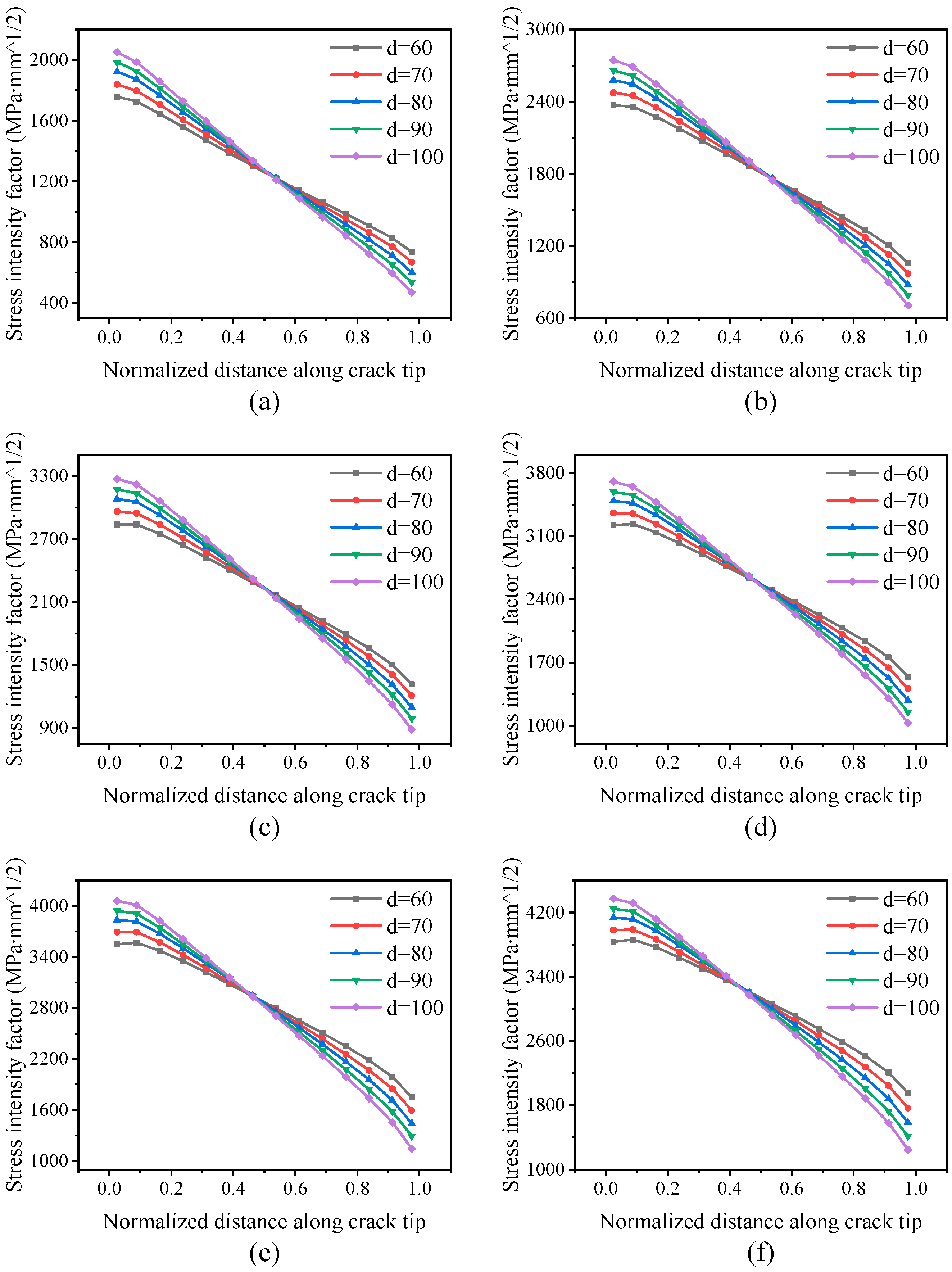
3.2. Influence of Rib Height on SIF of Crack Tip

The bending capacity, weight, dimension space and bearing capacity of the integral panel are directly affected by the rib height, so the reasonable rib height is very important, which is usually in the range of 25 mm–60 mm. The influence of rib height on the SIF at the crack tip was analyzed by using the integral plate finite element model with central through crack. Using the method of controlling a single variable, keep the dimensions of other parameters (L = 120, W = 100, tm = 5, d = 80, t = 4) of the panel unchanged, and set the ribbed height h as 10 mm, 20 mm, 30 mm, 40 mm and 50 mm respectively. The load on the model is M = 7.81 × 10⁶ N·mm. The specific parameters are shown in Table 4.
The SIFs at the crack tip under each group of parameters with different rib heights were obtained by finite element calculation, as shown in Figure 6.
It can be seen from Figure 6a that the trend of SIF with crack depth under different rib heights are relatively similar, with the SIF increases approximately linearly with the change of skin thickness. With the increase of the rib height, the slope of the curves decreases sharply, the curves tend to be flat, and the KI value at the crack tip decreases as a whole. It can also be seen from the figure that the curves of h10 and h20 are particularly steep and when the corresponding normalized distance of h10 curve is 0.65, the KI value even reaches 0, indicating that at this point, the crack tip is under compressive stress in the direction perpendicular to the crack surface. When the rib height reaches 30 mm, the slope of the curve becomes smaller, and continues to increase the rib height, the slope of the curves changes little. The above result shows that when the rib height is small, both the crack tip KI value and the maximum KI value decrease rapidly with the increase of rib height. However, when the rib height increases to a certain height, the effect of increasing the rib height on reducing the KI value of the crack tip is no longer obvious.
By comparing the six figures in Figure 6, it can be found that KI value of the crack tip increases as a whole with the crack propagation, and the ratio of increase is close to each other, and the shape and slope of the curve are almost the same. The above results show that the effect of rib height on the change velocity and amplitude of KI value at each point is consistent during the crack propagation.
The above analysis shows that when the rib height is small, the increase of the rib height can significantly reduce the integral crack tip KI value, and the integral panel’s fracture resistance can be enhanced. Figure 7 shows the comparison between the curve of the maximum SIF at the crack tip with rib height when the crack length is 5 mm and the influence of rib height on the SIF of the integral plate structure in the literature. The left ordinate is the SIF value of the FEM result, in MPa·mm^1/2. the right ordinate is the SIF value of the reference result, in MPa·m^1/2. Although the units of the two curves are not consistent, the comparison of the two curves shows that the influence of rib height on the stress intensity factor in this study is consistent with the conclusion in the literature. As you can see from Figure 7 and Figure 6, when the crack length a = 5 mm and rib height h increases from 10 mm to 30 mm, KI value decreases by 80%. When the rib height is large, the effect of increasing the rib height on the decrease of the crack tip KI value is weak, when h increases from 30 mm to 50 mm, KI value only decreases by 50%, and this effect does not change with the crack propagation. The change of rib height has a significant effect on the change of SIF at the crack tip of the integral panel. In order to ensure the fracture resistance of the integral panel, the height of the rib should be within a reasonable range, usually more than 30 mm.

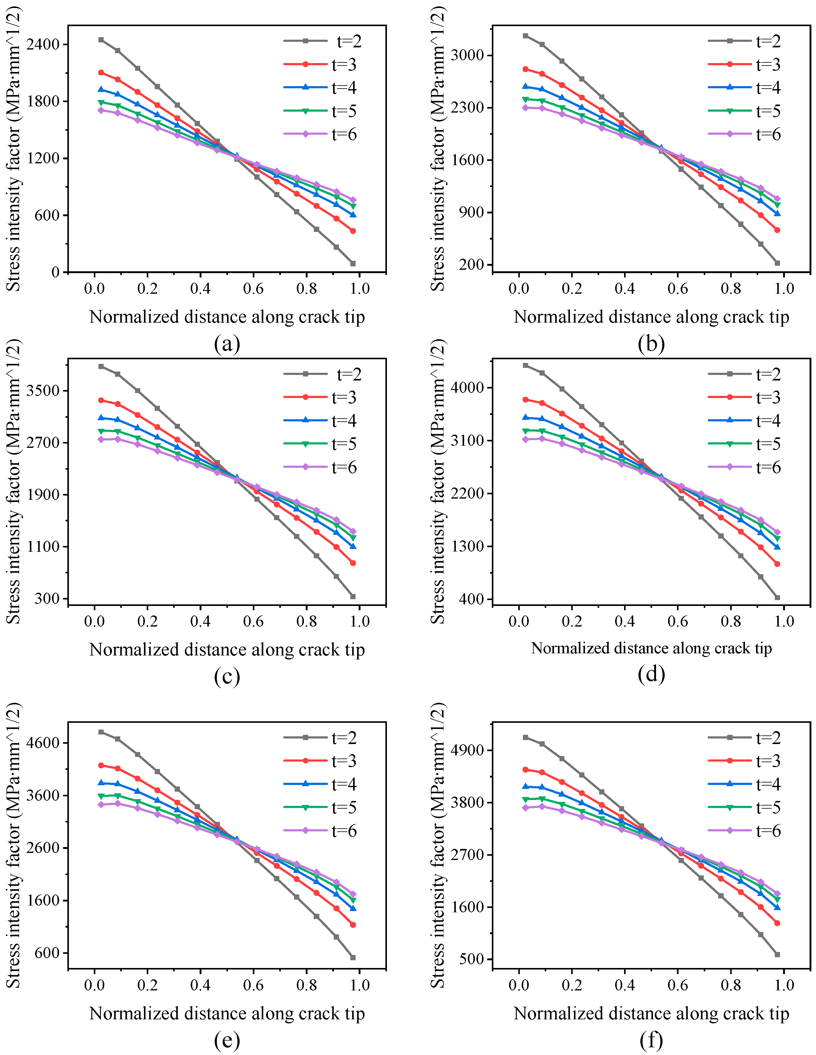
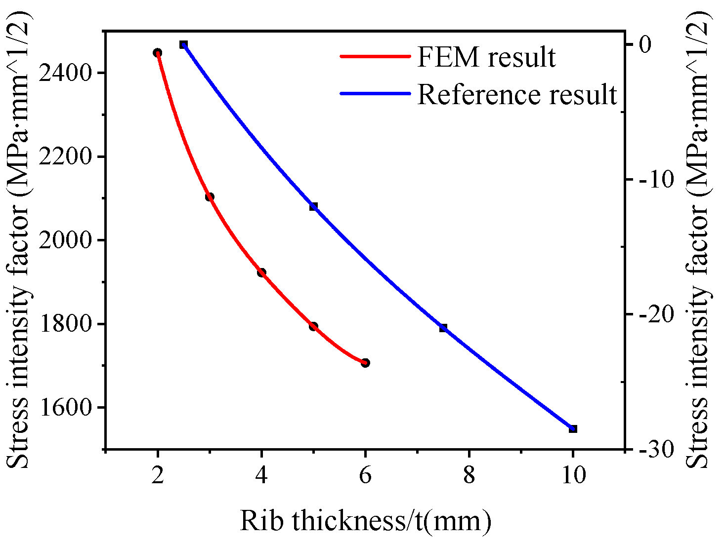
3.3. Influence of Rib Thickness on SIF of Crack Tip

The bearing capacity, ability to delay crack propagation and the weight of the integral panel are directly influenced by the rib thickness. The rib of the integral wall panel can not only bear the load, but also plays a certain role in preventing crack. The thicker the rib is, the stronger its ability to delay the crack propagation is. Therefore, it is necessary to study the effect of the rib thickness on the stress field of the wall panel crack tip. Similarly, the thicker the rib, the stronger its bearing capacity, but also increase the weight of the rib, thus a reasonable rib thickness of the rib is very important, which is usually in the range of 2.5 mm–7 mm. The influence of rib thickness on SIF at the crack tip was analyzed by using a finite element model of integral panel with center penetration crack. Using the method of controlling a single variable, keep the dimensions of other parameters (L = 120, W = 100, tm = 5, d = 80, h = 30) of the panel unchanged, and set the ribbed height t as 2 mm, 3 mm, 4 mm, 5 mm and 6 mm respectively. The load on the model is M = 7.81 × 10⁶ N·mm. The specific parameters are shown in Table 5.
The SIFs at the crack tip under each group of parameters with different rib thickness were obtained by finite element calculation, as shown in Figure 8.
It can be seen from Figure 8a that, when the crack length is 5 mm, the trend of SIF with skin thickness under different rib heights are relatively similar, with the SIF decreases approximately linearly with the change of thickness. With the increase of rib thickness, the slope of the curves decreases gradually, the curves tend to be flat. KI value of the area below the skin thickness center decreases, while KI of the area around the skin thickness center almost remains the same, and KI of the area above the skin thickness center increases. The above result shows that the minimum KI value of the crack tip increases with the increase of the rib thickness, while the maximum KI value of the crack tip decreases with the increase of the rib thickness. In a certain range, the rib thickness has a certain influence on the stress field at the crack tip of the whole wall plate, but this effect weakens with the increase of the rib height.
By comparing the six figures in Figure 8, it can be found that KI value of the crack tip increases as a whole with the crack propagation, and the ratio of increase is close to each other, and the shape and slope of the curves change very little. The above results show that the effect of rib thickness on the change velocity of KI value at each point is consistent during the crack propagation.
The above analysis shows that when the rib thickness is small, the increase of the rib thickness can significantly reduce the overall crack tip KI value, and the integral panel’s fracture resistance can be enhanced. The Figure 9 shows the comparison between the curve of the maximum SIF at the crack tip with rib thickness when the crack length is 5 mm and the influence of rib thickness on the SIF of the integral plate structure in the literature. The comparison of the two curves shows that the influence of rib thickness on the stress intensity factor in this study is consistent with the conclusion in the literature. As you can see from Figure 9 and Figure 8, when the crack length a = 5 mm and the rib thickness t increases from 2 mm to 4 mm, KI value decreases by 20%. When the rib thickness is large, the effect of increasing the rib thickness on the decrease of the crack tip KI value is weak, when t increases from 4 mm to 6 mm, KI value only decreases by 10%, and this effect does not change with the crack propagation. The change of rib thickness has a certain effect on the change of SIF at the crack tip of the integral panel. In order to ensure the fracture resistance of the integral panel, the thickness of the rib should be within a reasonable range, usually more than 4 mm.

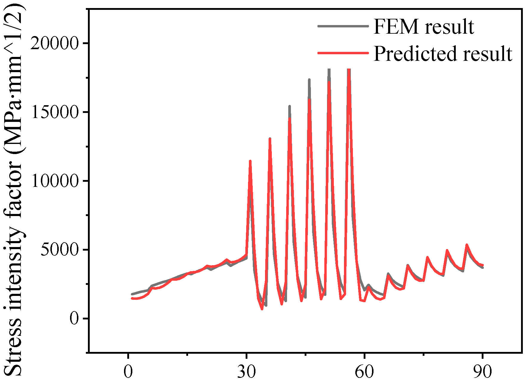
3.4. Prediction Model of SIF at Crack Tip of Integral Panel

In the above sections, taking the spacing, height and thickness of ribs as a single variable respectively, the influence of which on the SIFs of the integral panel was studied [28]. In this section, regression analysis was used to analyze the comprehensive influence of various parameters of rib structure on the SIFs of the integral panes in the process of crack propagation [29].
Based on the Taylor expansion method and the data of finite element results, taking the panel spacing of 80 mm, panel height of 70 mm, panel thickness of 4 mm and crack size of 5 mm as the starting point, the corresponding SIF as the starting value of the function, and considering the quadratic term of the expansion formula, the stress intensity of the integral panel was calculated by a multivariate nonlinear regression model taking the rib spacing, height, thickness and crack size as the function variables. The derivation model is as follows [15]:
K Ι ( d , h , t , a ) = K Ι 0 + c 1 d + c 2 h + c 3 t + c 4 a + c 11 d 2 + c 22 h 2 + c 33 t 2 c 44 a 2 + c 21 h d + c 31 t d + c 41 a d + c 32 t h + c 42 a h + c 43 a t + ε ,
where, K Ι ( d , h , t , a ) is the objective function, d is the rib spacing, h is the rib height, t is the rib thickness, a is the crack size, KI0 is the SIF at the starting point of expansion, c1 to c43 are various coefficients, and ε ( d , h , t , a ) is the higher order term of expansion error.
According to the simulation results, the coefficient of the regression model was solved, and the multi-element nonlinear relationship between the SIF and the rib spacing, rib height, rib thickness and crack size was obtained as follows:
K Ι = 109689.688 3210.940 d 9678.911 h + 83623.491 t + 443.002 a + 0.363 d 2 + 13.962 h 2 + 101.811 t 2 2.163 a 2 + 177.303 h d 539.879 t d + 0.237 a d 1380.146 t h 8.294 a h 7.048 a t ,
The established regression equation can be used to predict the crack tip SIF of the integral wall panel with different structural parameters in the process of penetrating crack propagation. The comparison between the FEM results and the predicted results is shown in Figure 10, in which the predicted values are obtained by the regression equation above.
The determination coefficient R2 was used to measure the accuracy of the model, the value range of coefficient R2 is 0 to 1. The closer the determinable coefficient is to 1, the better the goodness of fit of the model is, and its calculation formula is shown as follows:
R 2 = 1 ( y y ^ ) 2 ( y y ¯ ) 2 ,
where, y is the FEM value, y ^ is the predicted value, y ¯ is the mean value of the FEM, ( y y ^ ) 2 is the sum of the squared residuals of the regression model, and ( y y ¯ ) 2 is the sum of the squared total deviations of the model. Substitute the model prediction results and finite element results into Equation (7), the determination coefficient R2 of the regression model can be obtained to be 0.955. By determining the coefficient R and the high fitting of the two curves in Figure 10, we show that the predicted value of the model has a high degree of fit with the FEM value, and the prediction effect of the model is good.

4. Conclusions

In this paper, the influence law of integral panel structure parameters and crack size on SIF at crack tip is studied, the influence degree and trend of integral panel structure parameters on SIF are given, and the regression model of SIF at crack tip of integral panel is established. Through this study, the following conclusions can be drawn:
(1) among the integral panel structure parameters, rib height has the most obvious influence on the SIF at the crack tip, followed by rib thickness, and rib spacing has the least influence on the SIF, and this sequence does not change with the crack growth;
(2) increasing the height and thickness of the integral panel is conducive to improving the crack resistance of the entire wall plate, slowing down the crack growth rate and improving the damage tolerance. However, this lifting is limited; when the height and thickness of the panel increased to a certain size, the crack resistance of integral plate cannot continue to be improved.
(3) The predicted regression model result of SIF based on the integral plate structure parameters and crack size shows an acceptable agreement with the finite element results, with the determination coefficient of 0.955, indicating that the established regression model had a high prediction accuracy for this problem.

Author Contributions

Conceptualization, G.H., Y.B., W.Y. and L.Z.; Formal analysis, G.H., Y.B., W.Y., L.Y. and D.F.; Investigation, G.H., Y.B., L.Z., L.Y. and D.F.; Supervision, W.Y.; Validation, G.H., Y.B., L.Z., L.Y. and D.F.; Writing—review & editing, G.H., Y.B. and L.Z. All authors have read and agreed to the published version of the manuscript.

Funding

This research was funded by the National Natural Science Foundation of China (Grant Number 51327902, U1637601).

Conflicts of Interest

The authors declare no conflict of interest.

References

  1. Munroe, J.; Wilkins, K.; Gruber, M.; Domack, M. Integral Airframe Structures (IAS): Validated Feasibility Study of Integrally Stiffened Metallic Fuselage Panels for Reducing Manufacturing Costs. Available online: https://dl.acm.org/doi/book/10.5555/888417 (accessed on 16 June 2020).
  2. Zhang, X.; Boscolo, M.; Figueroa-Gordon, D.; Allegri, G.; Irving, P.E. Fail-Safe Design of Integral Metallic Aircraft Structures Reinforced by Bonded Crack Retarders. Eng. Fract. Mech. 2009, 76, 114–133. [Google Scholar] [CrossRef] [Green Version]
  3. Grbović, A.; Sedmak, A.; Kastratović, G.; Petrašinović, D.; Vidanović, N.; Sghayer, A. Effect of laser beam welded reinforcement on integral skin panel fatigue life. Eng. Fail. Anal. 2019, 101, 383–393. [Google Scholar] [CrossRef]
  4. Moreira, P.; Castro, P. Fractographic analysis of fatigue crack growth in lightweight integral stiffened panels. Int. J. of Struct. Integr. 2010, 1, 233–258. [Google Scholar] [CrossRef]
  5. Arrieta, A.J.; Striz, A.G. Optimal design of aircraft structures with damage tolerance requirements. Struct. Multidiscip. Optim. 2005, 30, 155–163. [Google Scholar] [CrossRef]
  6. Qi-qing, H.; Liu, J.; Yin, Z. Fracture Characteristics Analysis Method and Study of Wing-Beam Integrated structure. Aeronaut. Comput. Tech. 2006, 36, 114–116. [Google Scholar]
  7. Yan, X.; Wang, S.; Yi, S. Research and Analysis on Methods of Three-dimensional Crack Stress Intensity Factor for Integral Panel. Adv. Aeronaut. Sci. Eng. 2011, 2, 205–209. [Google Scholar]
  8. Šedek, J.; Růžek, R.; Raška, J.; Běhal, J. Comparative Study of Prediction Methods for Fatigue Life Evaluation of an Integral Skin-Stringer Panel under Variable Amplitude Loading. Procedia Eng. 2015, 114, 124–131. [Google Scholar] [CrossRef] [Green Version]
  9. Fossati, M.; Colombo, D.; Manes, A.; Giglio, M. Numerical modelling of crack growth profiles in integral skin-stringer panels. Eng. Fract. Mech. 2011, 78, 1341–1352. [Google Scholar] [CrossRef]
  10. Boscolo, M.; Allegri, G.; Zhang, X. Design and Modelling of Selective Reinforcements for Integral Aircraft Structures. Aiaa J. 2008, 46, 2323–2331. [Google Scholar] [CrossRef] [Green Version]
  11. Hoang-Ngoc, C.-T.; Paroissien, E. Simulation of single-lap bonded and hybrid (bolted/bonded) joints with flexible adhesive. Int. J. Adhes. Adhes. 2010, 30, 117–129. [Google Scholar] [CrossRef] [Green Version]
  12. Liao, Y.; Li, Y.; Pan, Q.; Huang, M.; Zhou, C. Residual fatigue life analysis and comparison of an aluminum lithium alloy structural repair for aviation applications. Eng. Fract. Mech. 2018, 194, 262–280. [Google Scholar] [CrossRef]
  13. Liao, Y.; Li, Y.; Huang, M.; Wang, B.; Yang, Y.; Pei, S. Effect of hole relative size and position on crack deflection angle of repaired structure. Theor. Appl. Fract. Mech. 2019, 101, 92–102. [Google Scholar] [CrossRef]
  14. Sun, Z.; Huang, M. Fatigue crack propagation of new aluminum lithium alloy bonded with titanium alloy strap. Chin. J. Aeronaut. 2013, 26, 601–605. [Google Scholar] [CrossRef] [Green Version]
  15. Heidari Shabestari, S.S.; Kayran, A. Development of a regression model for the life assessment of open-hole specimens with double through cracks utilizing stress intensity factor calculations via XFEM. Procedia Struct. Integr. 2019, 21, 154–165. [Google Scholar] [CrossRef]
  16. Narasimhachary, S.B.; Bhachu, K.S.; Shinde, S.R.; Gravett, P.W.; Newman, J.C. A single edge notch specimen for fatigue, creep-fatigue and thermo-mechanical fatigue crack growth testing. Eng. Fract. Mech. 2018, 199, 760–772. [Google Scholar] [CrossRef]
  17. Siegl, J.; Nedbal, I.; Kunz, J. Fatigue crack growth history in damage tolerance design of aircraft structures. Int. J. Fatigue 2009, 31, 1062–1067. [Google Scholar] [CrossRef]
  18. Bang, D.J.; Ince, A.; Noban, M. Modeling approach for a unified crack growth model in short and long fatigue crack regimes. Int. J. Fatigue 2019, 128, 105182. [Google Scholar] [CrossRef]
  19. Atroshchenko, E.; Potapenko, S.; Glinka, G. Stress intensity factor for a semi-elliptical crack subjected to an arbitrary mode I loading. Math. Mech. Solids 2014, 3. [Google Scholar] [CrossRef]
  20. Warzynek, P.A.; Carter, B.J.; Banks-Sills, L. The M-Integral for Computing Stress Intensity Factors in Generally Anisotropic Materials; NASA Technical Report Server: Ithaca, NY, USA, 2005.
  21. Newman, J.C.; Raju, I.S. An empirical stress-intensity factor equation for the surface crack. Eng. Fract. Mech. 1981, 15, 185–192. [Google Scholar] [CrossRef]
  22. Lv, F.; Zhou, C.-Y.; Cheng, R.-J.; Miao, X.-T.; He, X.-H. A numerical analysis based on M-integral about the interaction of parallel surface cracks in an infinite plate. Theor. Appl. Fract. Mech. 2018, 96, 370–379. [Google Scholar] [CrossRef]
  23. Sukumar, N.; Moes, N.; Moran, B.; Belytschko, T. Extended Finite Element Method for three-dimensional crack modelling. Int. J. Numer. Methods Eng. 2000, 48, 1549–1570. [Google Scholar] [CrossRef]
  24. Dhia, H.B.; Jamond, O. On the use of XFEM within the Arlequin framework for the simulation of crack propagation. Comput. Methods Appl. Mech. Eng. 2010, 199, 1403–1414. [Google Scholar] [CrossRef] [Green Version]
  25. Patil, V.; Chouhan, V.; Pandya, Y. Geometrical complexity and crack trajectory based fatigue life prediction for a spur gear having tooth root crack. Eng. Fail. Anal. 2019, 105, 444–465. [Google Scholar] [CrossRef]
  26. Lin, G.; Lin, H.; Zhao, Y. Aluminium Alloy Application Manual; China Machine Press: Beijing, China, 2006. [Google Scholar]
  27. Niu, C.; Feng, Z.; Cheng, X.; Zhang, J. Structural Stress Analysis and Dimension Design of Practical Aircraft; Aviation industry press: Beijing, China, 2009. [Google Scholar]
  28. Lima, M.M.; Godoy, C.; Avelar-Batista, J.C.; Modenesi, P.J. Toughness evaluation of HVOF WC–Co coatings using non-linear regression analysis. Mater. Sci. Eng. A 2003, 357, 337–345. [Google Scholar] [CrossRef]
  29. Geng, J.; Xu, J.; Nie, W.; Peng, S.; Zhang, C.; Luo, X. Regression analysis of major parameters affecting the intensity of coal and gas outbursts in laboratory. Int. J. Min. Sci. Technol. 2017, 27, 327–332. [Google Scholar] [CrossRef]
Figure 1. Comparison of assembled panel and integral panel.
Applsci 10 04142 g001
Figure 2. ABAQUS-FRANC3D co-modeling process.
Applsci 10 04142 g002
Figure 3. Finite element model of integral panel under bending load.
Applsci 10 04142 g003
Figure 4. Integral plate with initial through crack.
Applsci 10 04142 g004
Figure 5. Stress intensity factor (SIF) curves for crack lengths of (a) 5 mm, (b) 10 mm, (c) 15 mm, (d) 20 mm, (e) 25 mm, and (f) 30 mm.
Applsci 10 04142 g005
Figure 6. SIF curves for crack lengths of (a) 5 mm, (b) 10 mm, (c) 15 mm, (d) 20 mm, (e) 25 mm, and (f) 30 mm.
Applsci 10 04142 g006
Figure 7. Comparison of the effect of rib height on SIF between FEM result and reference result.
Applsci 10 04142 g007
Figure 8. SIF curves for crack lengths of (a) 5 mm, (b) 10 mm, (c) 15 mm, (d) 20 mm, (e) 25 mm, and (f) 30 mm.
Applsci 10 04142 g008
Figure 9. Comparison of the effect of rib thickness on SIF between FEM result and reference result.
Applsci 10 04142 g009
Figure 10. Comparison between the FEM results and the predicted results.
Applsci 10 04142 g010
Table 1. Material properties of 2024 aluminum alloy.
Material TypeTensile Strength
σb/MPa
Yield Strength
σ0.2/MPa
Elongation
%
Young’s Modulus
E/GPa
Poisson’s Ratio
ν
Fracture Toughness
Kc/MPa·mm1/2
202447032520720.334017
Table 2. Structural parameters of integral wall panels with different rib spacing.
GroupsModel Length L(mm)Model Width W(mm)Skin Thickness tm(mm)Rib Spacing d(mm)Rib Height h(mm)Rib Thickness t(mm)
1120100560304
2140100570304
3160100580304
4180100590304
52001005100304
Table 3. Bending loads of the model at different rib spacing.
Model Length L (mm)120140160180200
Bending load M (N·mm)5.86 × 1066.83 × 1067.81 × 1068.78 × 1069.76 × 106
Table 4. Structural parameters of integral wall panels at different rib heights.
GroupsModel Length L(mm)Model Width W(mm)Skin Thickness tm(mm)Rib Spacing d(mm)Rib Height h(mm)Rib Thickness t(mm)
1160100580104
2160100580204
3160100580304
4160100580404
5160100580504
Table 5. Structural parameters of integral wall panels with different rib thickness.
GroupsModel Length L(mm)Model Width W(mm)Skin Thickness tm(mm)Rib Spacing d(mm)Rib Height h(mm)Rib Thickness t(mm)
1160100580302
2160100580303
3160100580304
4160100580305
5160100580306

