1. Introduction
After the advent of the laser chirped pulse amplification (CPA) technique [
1] giving rise to high peak power femtosecond pulses, the laser wake field acceleration (LWFA) concept [
2] has become a routinely used experimental technique to generate electron beams by means of such ultrashort laser pulses [
3]. The main advantage in LWFA is represented by the presence of ultrahigh electric fields (GV/m–TV/m) generated by a plasma-wave, known as “wakefield”, which is a result of ponderomotive forces generated by a driving short laser pulse during its propagation into a pre-formed under-dense plasma. Electrons injected in such a wave can easily reach relativistic energies by being in phase with the wakefield and propagating behind the laser pulse, thus be accelerated to multi-GeV energies until the process is sustained.
In recent decades, various methods have been proposed and experimentally tested to extend maximum plasma length over which the acceleration process takes place [
4,
5,
6,
7,
8,
9]. In fact, as it is well known, a focused laser pulse can sustain its peak intensity only within the “Rayleigh length” determined by the given focusing optics, thus such a length limits the maximum distance over which an efficient acceleration occurs and, as a consequence the maximum energy gain of the accelerated electrons. Guiding a short laser pulse well beyond its Rayleigh length is possible by using plasma densities that allow laser self-focusing in the ionized gas. However, such a process is sensitive to plasma instabilities [
3].
On the other hand, stable plasma guiding methods have been demonstrated experimentally, and allowed to accelerate electron bunches up to 8 GeV, as described in [
10,
11]. This experimental technique is based on the use of a capillary–discharge gas target in combination with a laser heater, which allows the generation of a parabolic plasma-channel used, in turn, to guide an additional driving high peak-power laser pulse over a distance of about 10 cm. Nevertheless, a disadvantage of such a discharge capillary target is represented by the experimental limitation in terms of optical probing of the plasma and bunch dynamics, due to the presence of the capillary walls. Additionally, the capillary input region can rapidly deteriorate due to the incoming high intensity laser pulse, even if such an effect is mitigated by the use of the laser heater. Various studies focus on peculiar aspects of such capillary–discharge based approaches [
12,
13,
14]. The basic idea is that, by means of the electric discharge, energy is released on the main cylindrical axis of the capillary–discharge-target to produce a cylindrical expansion that generates a lower density profile in proximity of the plasma axis.
A different approach consists in using an axicon lens and a femtosecond laser beam to release energy into the cylindrical plasma axis and produce plasma-channels, as reported in the literature [
15]. The advantages of using all-optical techniques for generating the required plasma-channel characteristics are absence of target deterioration effects, and possibility of optical probing of the plasma density evolution during laser-plasma interaction. Moreover, the all-optical approach allows for a more sophisticated release of the energy in time, in principle up to the femtosecond scale, by using different laser pulses or a time-modulated one. The time dependence of the energy release is of high importance for the hydrodynamic plasma evolution to explore new parameter ranges. The experimental approach presented here investigates the possibility of generating plasma-channels in an all-optical geometry by using a cylindrical lens and a nanosecond laser pulse with moderate intensity. In future experiments, time-modulated nanosecond laser pulse may be considered. The cylindrical lens is used to release the energy into the main plasma axis, similarly to the discharge-capillary target. The nanosecond energy release produces a cylindrical expansion with a hydrodynamic evolution potentially favorable for femtosecond laser guiding and LWFA. Ad-hoc numerical modeling confirming this concept and discussing its limitations are reported in the literature [
16]. For instance, a clear challenge of this approach for future LWFA setups is the generation of plasma channels with cylindrical symmetry in the transverse plane with respect to the femtosecond laser propagation axis. Such symmetry is intrinsic in the case of a capillary–discharge-target. This pilot experiment aims to investigate on the parameters required to overcome such asymmetrization effects in a realistic scenario. In such a setup an elongated focus or knife-like focus (high-aspect-ratio), having the same length of the required plasma-channel is produced. Such method has been proposed as an additional guiding solution for the high repetition-rate user experimental platform High-energy electrons by laser light (HELL) at ELI-Beamlines (Extreme Light Infrastructure in the Czech Republic) [
17].
2. Concept of Elongated Focus for Plasma-Channel Generation
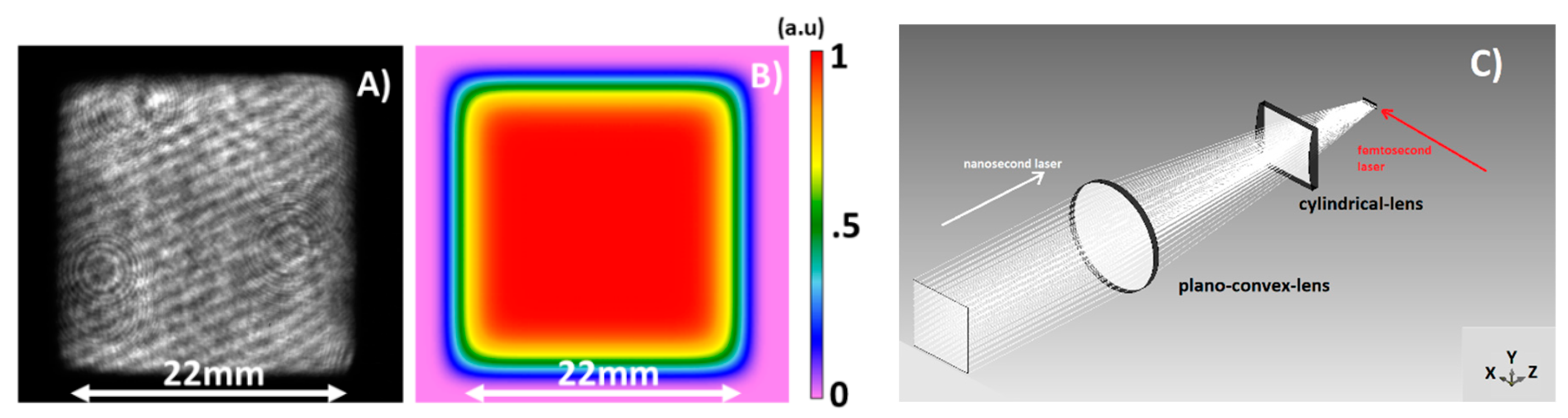
The idea of using a cylindrical lens to generate an elongated laser focus is applied to generate a high-aspect-ratio in the transverse focal plane (shown as x-y plane, see
Figure 1C) with respect to the longitudinal nanosecond laser optical axis (shown as z-axis, see
Figure 1C). For the use of a plasma channel in LWFA a femtosecond laser traveling on the x-axis needs to be focused into the plasma channel for guiding over the entire channel length.
Figure 1C illustrates this concept. The femtosecond laser interaction is not considered here.
Considering the available laser parameters of 5 J, 10 ns, 22 × 22 mm
2 beam size, and a desired plasma-channel length of about 5 mm, it was necessary to use a 200-mm plano-convex lens in combination with the cylindrical lens (100-mm focal length), in order to increase the laser intensity up to 10
12 W/cm
2. The optical scheme used for the elongated focus generation (shown in
Figure 1C), also called “knife-like” focus, was already considered and reported for an ad-hoc numerical study on plasma hydrodynamic effects [
16]. The measured spatial distribution of the Bivoj nanosecond laser is shown in
Figure 1A, and the simulated one in
Figure 1B. The resulting simulated high-aspect-ratio shape of the laser focus is shown in
Figure 2. Corresponding measurements performed at low laser power are shown in
Figure 3. Numerical simulations performed by the Virtual Lab Fusion software show a peak intensity of 1.7 × 10
12 W/cm
2 sustained over 5 mm [
18]. The simulated diameter of the focus along the y-axis was 6 µm full-width-half-maximum (FWHM) and the measured one 7 µm FWHM, calculated by averaging it over 100 µm of the x-axis, as shown in
Figure 3-bottom. The measured full length of the focal distribution along the x-axis was 5.3 mm (10% variations of the intensity value). An example of the spatial profile, measured in a limited region of 2 mm due to field-of-view limit, is shown in
Figure 3-top.
In general, an optimal guiding process requires a symmetric plasma channel in the z-y plane. This is an important feature of the intensity distribution on the z-y plane, i.e., the transverse plane with respect to the propagation direction (x-axis) of a subsequent femtosecond laser beam.
Figure 4 illustrates such a geometry (
Figure 4a) and the corresponding numerical simulation (
Figure 4b). As clearly shown by numerical simulations, the region of high laser intensity is strongly asymmetric for the given optical configuration: the focus width is about 6 µm FWHM along the y-axis and 200 µm FWHM along the z-axis. A shorter focal-length of the cylindrical lens would be required if one wanted to improve the symmetry of the focus in the z-y plane. As an example, reducing by a factor of 2 the focal lengths of the two lenses would give a FWHM along the z-axis of about 120 µm. Additional improvement can be reached using a telescope to increase the laser beam transverse dimensions. In this case reducing the f/number of the system would improve the symmetry without any reduction of the focal length of the cylindrical lens, thus maintaining a reasonable distance from the plasma source and preventing potential deterioration. However, in a first approximation, a certain degree of asymmetry (or unwanted optical artifacts) will remain compared to the ideal configuration of perfectly cylindrical symmetry laser fields. Additionally, considering laser intensity distribution and phase front fluctuations, even an ideal cylindrical laser field geometry could fail to generate shot-to-shot reproducible symmetric plasma channels. In principle, all these unwanted effects can be mitigated by a proper control of the nanosecond laser intensity range (upper and lower limits) within a confined radial region around the cylindrical axis, which is smaller than the desired channel diameter resulting from the hydrodynamic cylindrical expansion.
The main goal of the experiment was to investigate such laser intensity threshold and proper range (upper and lower limits) for the future generation and control of symmetric plasma channels in gas targets of interest for LWFA. In the following, we will refer to the term significant-intensity-threshold. Such threshold can be estimated generating simpler elongated plasma structures (asymmetric channels). This experimental threshold depends critically on the gas atomic species and on the operational backing pressure of the gas target (i.e., gas density). The present experimental work was focused on investigation of the conditions for reproducible elongated plasma structures using various gases and pressures. The laser significant-intensity-threshold was estimated without any attempt to generate symmetric plasma channels.
The laser significant-intensity-threshold required to generate a shot-to-shot reproducible plasma from a gas target is a key parameter, also if one aims to extend the plasma channel length over tens of centimeters and beyond. From this point of view, in our experimental conditions, gases with higher atomic species are favorable due to a required lower laser energy per unit length of the channel and to a lower plasma radial expansion velocity. Consequently, we have used Ar and N having the same specific heat ratio with respect to He and H gases (key parameter from a gas dynamic point of view), which are more frequently used in LWFA. It is worth mentioning that estimation of the significant-intensity-thresholds for given gas species and pressure conditions provide a rough indication of the behavior of different gas species based on ionization potentials and laser absorption processes, if the ultimate goal remains to confine the nanosecond laser energy within a certain volume, thus leading to the generation of a symmetric cylindrical plasma expansion.
Standard laser-target experimental conditions were used in the experiment: 10 ns, 5-J laser pulse with gas target pressure in the range 20–60 bar. A relatively high pressure was used for two reasons. First, the hydrodynamic expansion generates a density drop of 1–2 order of magnitudes in proximity of the axis. Second, a low gas neutral density would lead to an excessively high plasma expansion velocity, thus limiting the future scalability of this experimental concept to longer plasma channels. In fact, future availability of the 100-J beamline of the Bivoj laser at the HiLASE (High average power pulsed LASErs) research center is considered to extend this work to formation of plasma channels with lengths of several tens of cm [
19,
20]. This study is limited to the generation of ns-plasma elongated structures and no investigation of fs-laser pulse propagation is presented.
3. Experimental Setup
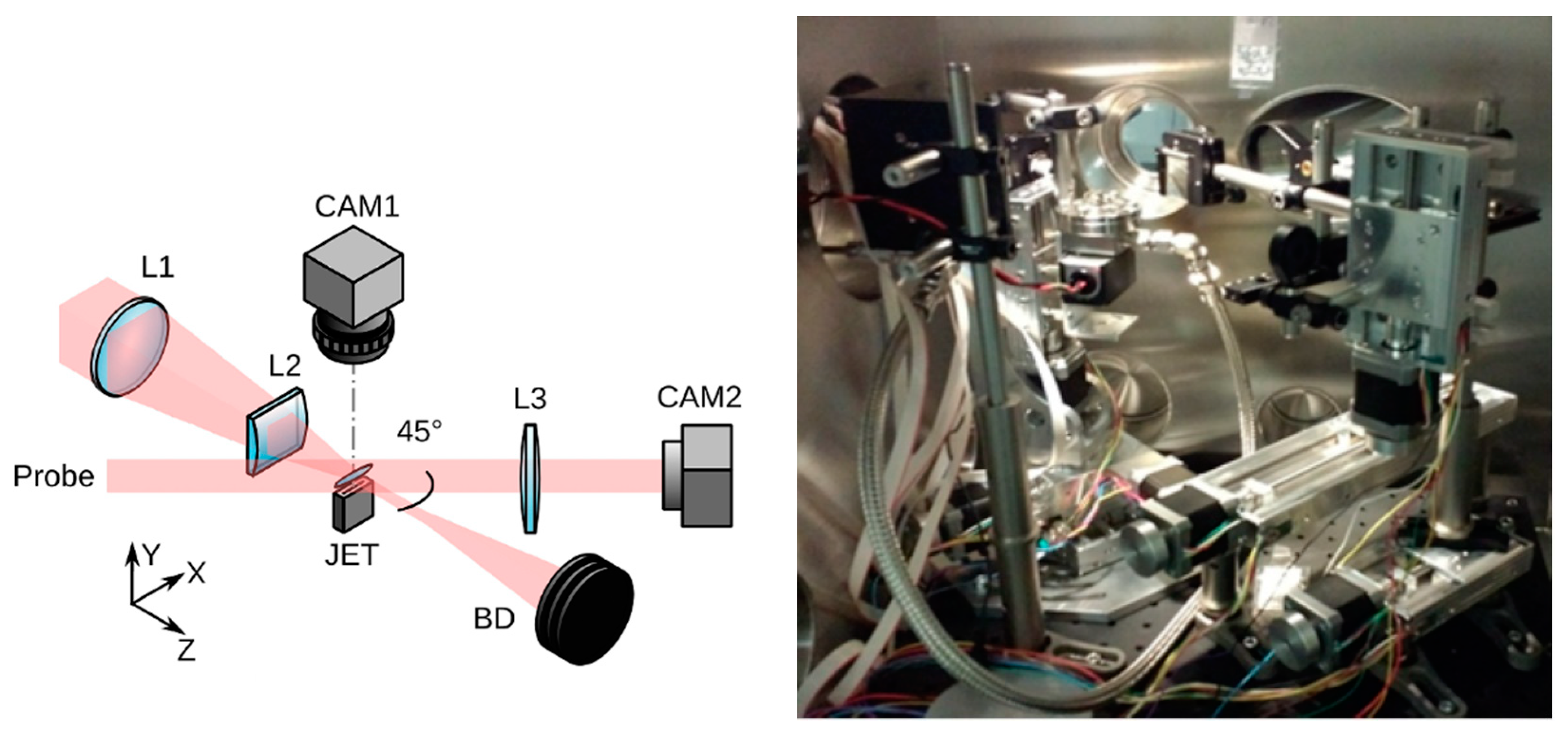
As sketched in
Figure 5, a 10-ns laser pulse operating at a wavelength of 1030 nm with variable energy in the range 1–5 J was focused into a gas-jet target. The laser focus was located 1 mm above the 6.8 mm × 1.26 mm rectangular pulsed supersonic gas nozzle. The nozzle was operated with Nitrogen (N) or Argon (Ar) gas. The valve backing pressure was varied in the range of 20–64 bar, corresponding to a gas density in the range 2–6 × 10
19 atoms/cm
3 (1 mm above the nozzle). The gas density profile was measured experimentally and simulated using the FLUENT code (details are available in [
21]). The gas density profile was uniform along the 1.26-mm side (or z-axis) for the Ar case, while for the N case two peaks were present at the boundaries with density increase of 1.15 times the density at the center. Along the 6.8-mm side (or x-axis), two large peaks on the boundaries were present for the Ar case with a density increase of a factor 2 with respect the center, while for the N case a similar profile was present with a factor of 1.4. As already mentioned, Ar and N have a specific heat ratio equivalent to helium (He) and hydrogen (H) (1.66 for Argon and Helium and 1.4 for Nitrogen and Hydrogen), thus producing very similar neutral gas density profiles. In order to characterize the generated plasma during laser irradiation, a portion of the main laser beam (a leak from one of the turning mirrors) was used as optical probe beam (45°-incidence angle with respect to the optical axis). A shadowgraphy technique was used, as shown in
Figure 5 (CAM2). Additionally, a top-view imaging system was setup to provide complementary information on plasma generation through emission of plasma light in the optical window as sketched in
Figure 5 (CAM1), integrated over 10 µs, hence, also collecting the late phase of the plasma light emission.
A proper delay between the main and the probe beam was chosen to optimize the plasma shadowgraphy raw images. The laser energy level was gradually reduced to determine the minimum value of energy required to generate a fully continuous plasma column along the gas-jet length, as well as a fully continuous optical emission. These results were used to estimate as the above mentioned laser significant-intensity-threshold. These values can be considered as a laser intensity upper threshold (overestimation) for local plasma formation (ionization threshold).
Measurements of the elongated focus carried out in the experimental campaign demonstrated that the main laser beam was focused approximately into a 7 µm × 5.3 mm elongated structure, as shown in
Figure 3. This was in good agreement with the optical simulations presented in
Figure 2. In the conditions of minimum laser intensity for uniform plasma formation (the significant-intensity-threshold), the elongated plasma structure inner diameter was measured experimentally both for Ar and N targets (see
Section 4) in the x-y plane. Since the hydrodynamic evolution of the plasma structure was not constant during the 10 ns laser probe duration, the inner radius measurement must be considered an average value and is presented here only for a quantitative estimation of the significant-intensity-threshold. This cannot be considered for an absolute estimation of the inner plasma structure dimensions. In fact, the latter could be measured only using an optical probe with a shorter pulse duration, along with an interferometric method to estimate the channel inner density profile that is out of the scope of the present work.
It is worth mentioning that the optical probe beam propagated through the plasma channel on the same plane of the main laser axis, i.e., through the elongated focus (45° incidence angle). Consequently, shadowgraphy images could provide only an averaged estimation of the channel inner diameter, which was transverse to such a plane (x-y plane). Thus, any channel asymmetry occurring along the longitudinal direction (z-axis) could not be measured. In fact, as mentioned above, estimation of the significant-intensity-thresholds was the main aim of this experimental work and no additional shadowgraphy line was setup.
4. Experimental Results and Discussion
Various high-aspect-ratio plasma structures were produced.
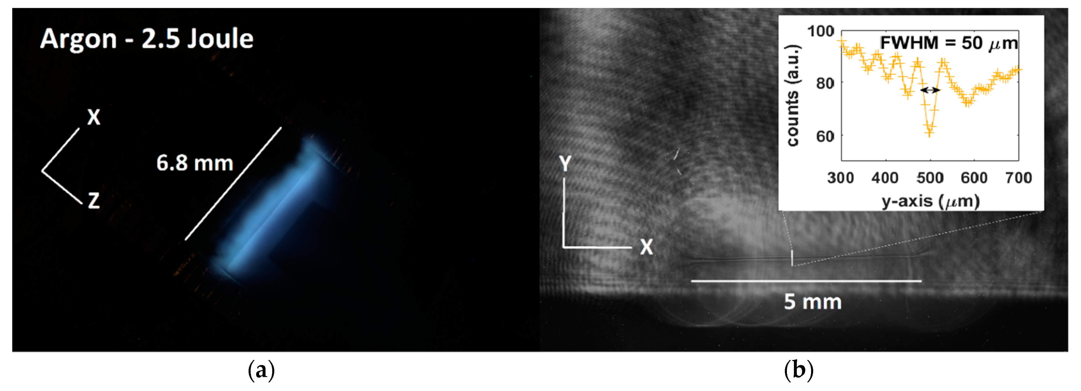
Figure 6b shows the structure of the elongated plasma in the shadowgraphy image.
Figure 6a shows the top-view of the optical plasma emission for the same shot in Ar at a baking pressure of 51.2 bar and a laser energy of about 2.5 J. In these experimental conditions, a fully continuous elongated plasma structure and optical plasma emission is clearly visible along the entire long focus.
Figure 7 summarizes results obtained in Ar at 51.2 bar and different laser energies.
Figure 7a shows the shadowgraphy profiles along the y-axis, averaged over 1 mm of the structure in the x-axis.
Figure 7b shows the optical plasma emission averaged along the entire z-axis. At 0.9 J, no plasma is generated. In the 1.67-J case a plasma is generated, however the entire elongated plasma structure is not uniform, but roughly reproduces the gas-jet density profile, as detected by optical plasma emission. In this specific case, a similar profile is present in the shadowgraphy. At the value of 2.5 J an entirely formed elongated plasma structure, with an improved degree of uniformity, is present both in the shadowgraphy and in the optical plasma emission.
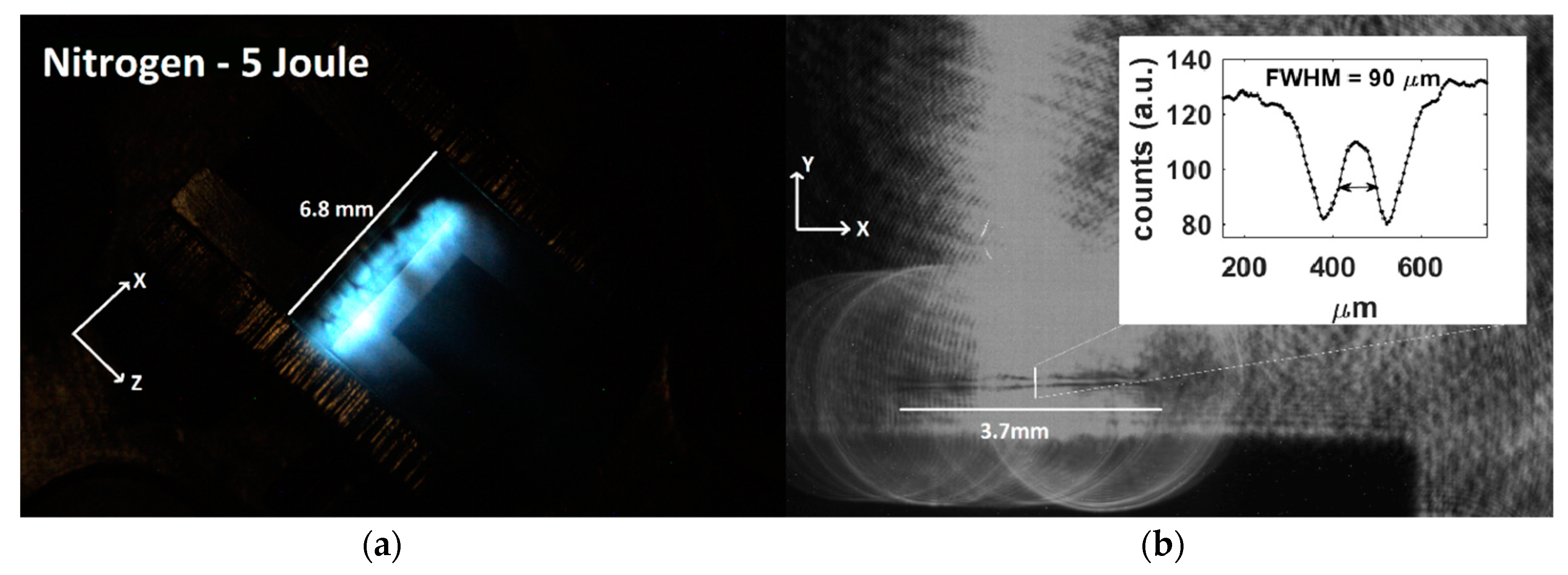
Figure 8b shows the structure of the elongated plasma in the shadowgraphy image.
Figure 8a shows the top-view of the optical plasma emission for the same shot in N at a backing pressure of 64 bar and a laser energy of about 5 J. In these experimental conditions, a fully continuous elongated plasma structure and optical plasma emission is clearly visible along the entire long focus.
Figure 9 summarizes the results obtained with Nitrogen at a backing pressure of 64 bar for different laser energy.
Figure 9a shows the shadowgraphy profiles along the y-axis, averaged over 1 mm of the structure in the x-axis.
Figure 9b shows optical plasma emission averaged along the entire z-axis.
In the 4.2-J case a plasma channel is created, but this presents a low degree of uniformity through its entire length, as detected by optical plasma emission. In the 3.3-J case, no plasma is generated, as confirmed by the absence of optical plasma emission. Based on shadowgraphy images and plasma optical emission, various kinds of uniformities can be seen. This information is taken into account for an estimation of the laser-significant intensity-threshold—and for considerations of the best laser focusing conditions—with the aim to localize the incoming laser energy within a region that evolves symmetrically during the hydrodynamic expansion.
In summary, elongated plasma structures of about 5-mm long and 50-µm wide were measured in Argon, while 3.7-mm long and 90-µm wide were estimated in the Nitrogen case. Such quantities were measured after 10 ns from the arrival of the laser pulse by using a probe beam which was 10 ns long and using an integration time of 10 µs for the cameras.
The significant-intensity-threshold estimation is a conservative estimation (upper threshold) of the laser intensity for localized plasma formation. In fact, the plasma ionization threshold can occur in localized region where local laser intensity or local gas density levels are favorable for plasma formation, but this does not occur along the entire elongated plasma structure.
For a quantitative estimation of the significant-intensity-threshold upper and lower bound, we studied the optical plasma emission dependence on the laser energy. The optical plasma emission is measured by calculating the blue-channel value integrated over the gas-jet area in the plasma top-view images. The minimum energy value allowing an optical plasma emission is recorded when a small localized plasma is generated. Increasing the laser energy, the optical plasma emission signal increases, until it reaches a saturation level. Such saturation value resulted to be higher than the energy level corresponding to the generation of an entirely elongated plasma structure in the shadowgraphy images. Consequently, one can deduce that the significant-intensity-threshold, in a first approximation not considering density profile modulations, is confined within such an optical emission dynamic range. A simple threshold model was used to fit the experimental data in the following form:
where
Elaser is the laser energy,
Es.i.t. is the energy corresponding to the upper boundary of the significant-intensity-threshold range,
a,
k and
cost are the other free parameters of the fit.
Figure 10 shows the dependence of the plasma optical emission (blue-channel) on the laser energy for both Ar (52.1 bar pressure) and N(64 bar) gas targets.
The laser energy range for plasma generation is 3.5–5 J in the case of N gas target and 0.9–2.5 J in the Ar case. The lower boundary corresponds to a local plasma formation (plasma ionization threshold). The upper boundary corresponds to the formation of an entirely elongated plasma structure, both in the optical and in the shadowgraphy images, thus independently from the gas-jet density profile variations. It is worth mentioning that to avoid an excessive radial plasma extension from the cylindrical axis, beyond the radial extension required to have a symmetric hydrodynamic expansion, such density variations will be important in future, thus a lower boundary level is preferable for our considerations. For this reason, we rely on the Es.i.t. value obtained from the data fit, i.e., 1.7 J for Ar and 4.2 J for N. Moreover, to determine the significant-intensity-threshold, it is important to take into account the variations of plasma generation coming from laser energy fluctuations (total energy fluctuations or longitudinally local variations) or from gas density fluctuations. Such variations can be mitigated more easily if one operates in a laser/energy intensity range where the curves shown in Fig.10 present a smaller slope.
Based on these considerations, we can conclude that the laser significant-intensity-threshold falls in the energy range of 3–4 J (corresponding to a peak intensity 5–6.7 × 10
11 W/cm
2) for a N-gas at the backing pressure of 64 bar (6 × 10
19 atoms/cm
3 neutral density) and 0.9–1.5 J (corresponding to 1.4–2.7 × 10
11 W/cm
2) for an Ar-gas at the backing pressure of 51.2 bar (5 × 10
19 cm
3 atomic density). Such estimations are in agreement with similar estimations present in literature [
22,
23].
5. Conclusions
The use of a nanosecond laser pulse for generation of 5-mm long and tens of microns wide elongated plasma structures in a gas-jet was demonstrated experimentally. Estimation of the significant intensity threshold formation useful for a future symmetrization of the plasma channel is reported for Ar and N. The results indicate that further investigation is needed for the symmetrization of the channels and that such laser-plasma interaction conditions are accessible with joule-class, nanosecond lasers. Moreover, such results establish an optimal energy/intensity working range for future studies focused on symmetrization issues, along with a preliminary assessment on needed adjustment of the focusing optics, as well as use of additional plasma diagnostics. In particular, this experimental technique will require a second probe beam to measure the degree of symmetry of the plasma channel. Additionally, a shorter laser probe pulse will be required to measure the instantaneous density profile inside the plasma channel, as well as monitoring its expansion velocity. This approach allows to use time-modulated energy release (temporally shaped laser pulse) with additional control of the cylindrical hydrodynamic evolution over a wider space of parameters.
This work represents an important step towards future implementation of such potentially innovative experimental approach for generation of symmetric plasma-channels with required lengths, both in a single stage and in a multi-stage LFWA scheme, thus potentially promising for implementation of future compact accelerators aimed to produce high-energy electrons by laser light.


 ,
, 


