Abstract
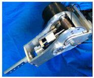
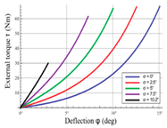
Robots are gaining a foothold day-by-day in different areas of people’s lives. Collaborative robots (cobots) need to display human-like dynamic performance. Thus, the question of safety during physical human–robot interaction (pHRI) arises. Herein, we propose making serial cobots intrinsically compliant to guarantee safe pHRI via our novel designed device, V2SOM (variable stiffness safety-oriented mechanism). Integrating this new device at each rotary joint of the serial cobot ensures a safe pHRI and reduces the drawbacks of making robots compliant. Thanks to its two continuously linked functional modes—high and low stiffness—V2SOM presents a high inertia decoupling capacity, which is a necessary condition for safe pHRI. The high stiffness mode eases the control without disturbing the safety aspect. Once a human–robot (HR) collision occurs, a spontaneous and smooth shift to low stiffness mode is passively triggered to safely absorb the impact. To highlight V2SOM’s effect in safety terms, we consider two complementary safety criteria: impact force (ImpF) criterion and head injury criterion (HIC) for external and internal damage evaluation of blunt shocks, respectively. A pre-established HR collision model is built in Matlab/Simulink (v2018, MathWorks, France) in order to evaluate the latter criterion. This paper presents the first V2SOM prototype, with quasi-static and dynamic experimental evaluations.
1. Introduction
The currently emerging manufacturing paradigm, known as Industry 4.0, is behind the rethinking of how industrial processes are designed in order to increase their efficiency and flexibility, together with higher levels of automatization [1]. To this end, Industry 4.0 integrates multiple technologies such as the Internet of Things (IoT) [1], artificial intelligence (AI) [1], and cyber-physical systems. Accordingly, robotics researchers are proposing new solutions [2,3] whereby collaborative robots, known as cobots, physically collaborate with well-qualified operators to achieve the goals of this revolution. Hence, the problem of the human subject’s safety vs. the robot’s high dynamic performances arises. This means that the next generation of widely used cobots should manifest human-friendly attributes. In the literature, two main approaches were proposed to tackle this problem: active impedance control (AIC) and passive compliance (PC). In the former, the impedance [4] is controlled to display safe behavior vis-à-vis the robot’s environment, including the humans within it. In the case of a fast human–robot (HR) collision, this approach, because it cannot respond as quickly as within 200 ms [5,6], can allow severe damage to the impacted human [7]. As a result, the PC approach attracted interest due to its instantaneous reaction to any potential impact. This latter, potential impact is defined as a quantification of the maximum impact force a robot can exert in a collision with a stationary object [8]. To emphasize, it is the combination of high mobile inertia and high velocity (i.e., the high kinetic energy) that makes robots dangerous [7,9]. With this in mind, achieving safety without compromising the desired dynamics boils down to reducing the reflected inertia, which is the key feature of the PC approach. Indeed, from a dynamic perspective, integrating passive mechanisms in robot joints decouples a certain colliding inertia from the rest of the robot. This reduces the overall kinetic energy absorbed by the impacted human. In line with this, the series elastic actuator [10] is among the first solutions that has a constant stiffness profile. A passive compliance system composed of purely mechanical elements often provides faster and more reliable responses to dynamic collisions [11]. To enhance the latter’s design capacity to react to load variation, a series parallel elastic actuator was introduced by Mathijssen and co-workers [12]. To improve the safety of physical human–robot interaction (pHRI), Zinn et al. presented [13] a distributed macro-mini (DM [2]) actuation system that puts forward low-inertia actuators to interact with the human subject. This allows for both safety and a fast control reaction via the low inertia actuated part. In order to deal with any unsupervised collision while handling variable loads, the concept of the variable stiffness actuator (VSA) emerged. Through the years, several VSAs have been proposed, as discussed in previous studies [3,14]. Their design concepts resulted in different structural paradigms (e.g., serial or antagonistic), different stiffness profiles, and a wide range of power to mass ratios. Herein, a great emphasis is placed on a VSA’s stiffness profile vs. the safety aspect. The proposed approach, leading to prototype V2SOM (variable stiffness safety-oriented mechanism) [1], presents the following novelties compared to the literature:
- The stiffness behavior, in the vicinity of zero deflection, is smoothened via a cam follower mechanism.
- The stiffness sharply sinks to maintain, theoretically, as discussed in Section 2, a constant torque threshold in case of a collision.
- The torque threshold, , is tunable according to the load variation.
This paper presents the V2SOM design as well as a simulation and experimental validations. V2SOM is primarily conceived to enhance safety in normal working routines, as well as in the case of uncontrolled HR collisions. In Section 2, this aspect is discussed in light of a comparative study between several stiffness profiles. Then, V2SOM’s working principle and mechanical structure are illustrated. In Section 3, the impact of V2SOM on human safety is studied in terms of two complementary safety criteria: the head injury criterion (HIC) and impact force criterion (ImpF). The study is carried out via a HR collision model simulation found in previous works [15,16]. The experimental validation of the V2SOM is presented in Section 4. This section includes the quasi-static characterizations as well as the HR collision tests. Section 5 summarizes the outcomes of the present study and gives some future perspectives.
2. Materials and Methods
The VSA’s design concept aims to make load-adjustable compliant robots by implementing a variable stiffness mechanism (VSM) in series with the actuation system, as depicted in Figure 1. However, a VSM can simply be described as a tunable spring with a basic nonlinear stiffness profile. With this in mind, we will discuss the properties of the different existing basic stiffness curves and highlight the V2SOM profile that we propose in this work.
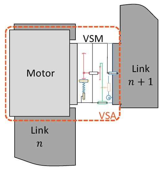
Figure 1.
Variable stiffness actuator (VSA) including the variable stiffness safety-oriented mechanism (V2SOM).
2.1. Different VSMs’ Basic Stiffness Curves
Previous works on VSAs resulted in design concepts that differ in several aspects, such as mass to volume ratio, elastic energy to mass or volume ratios, working principal, etc. (see [13,17,18,19,20] for more details). Herein, we focus on the VSA’s stiffness profile. The VSAs mentioned in other studies (see [14,17,18,19,20], representative of the current state-of-the-art) can be classified into one of the three categories illustrated in Table 1.

Table 1.
The three main categories of VSAs according to their stiffness characteristic.
The stiffness profiles of VSAs might be viewed singularly as a tunable basic stiffness profile. These basic stiffness profiles are shown in Figure 2:

Figure 2.
Different basic torque curves and V2SOM stiffness curves: (a) Constant stiffness, (b) Biomimetically inspired stiffness, (c,d) V2SOM basic curves.
- Constant stiffness: this basic stiffness profile is shown in Figure 2a and exemplified in the second column of Table 1 by an actuator with adjustable stiffness (AwAS-II) [19]. At each curve of the AwAS-II characteristic, the stiffness remains practically constant. To adapt this mechanism to a variable load, the torque’s slope is tuned via a small motor.
- Biomimetically inspired stiffness, shown in Figure 2b, represents different VSAs, such as the ones developed at the German Aerospace Center (DLR) Institute of Robotics and Mechatronics, the floating spring joint (FSJ) [20], QA-joint (Quasi-Antagonistic Joint) [21], FAS (Flexible Antagonistic Spring) [22] or the one presented by Ayoubi et al. [23]. The third column of Table 1 shows the floating spring joint (FJS) prototype with a stiffness that increases along with the deflection, the same as in biological muscles [23].
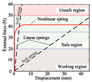
- Torque limiter: Park introduced [24,25] the safe joint mechanism (SJM) (see fourth column of Table 1), which is based on a slider-crank mechanism. Its basic stiffness curve corresponds to the one in Figure 2c. This mechanism is supposed to remain stiff under a certain torque level . Upon exceeding it, the stiffness rapidly drops to maintain the torque at level, which represents the safety threshold. As the SJM is a slider-crank-based mechanism that is well known for its sensitivity to friction in the vicinity of zero deflection, the safety threshold may be easily exceeded in the case of blunt shocks, as shown by Park and colleagues [26]. For this reason, we introduced the V2SOM basic curve (see Figure 2c,d). In the next section, the full V2SOM characteristic, which allows for coping with load variation, unlike the SJM, is shown. The latter curve presents a finite value stiffness near zero deflection, which continuously drops to display a constant torque threshold . The following equation depicts the desired behavior:where s is a positive constant and the elastic deflection angle is in the range of 0 to .
To compare the three stiffness profiles, we adopted the following factors:
- Factor 1. The maximal stored elastic energy in “normal working conditions,” (i.e., not during collision scenarios). This quantifies how much elastic energy is stored in the VSM that can be unleashed as collision kinetic energy, hence increasing the damaging effect of a potential collision.
- Factor 2. Passive torque limitation: in the case of a fast HR collision, it is more convenient to instantaneously contain the exerted torque with the VSM rather than as a control-based reaction [5,6].
- Factor 3. Gravity-induced elastic deflection: this criterion quantifies the VSM’s ability to passively limit this elastic deflection, which reduces the controller’s compensation action.
Based on the three factors, we ranked the stiffness profiles in Figure 2 accordingly, where the number of ‘+’ reflects the factor’s qualitative value. The results are given in Table 2, which shows that the V2SOM basic curve displays better features in normal working conditions (i.e., factors 1 and 3), and in a collision scenario based on factor 2.

Table 2.
Results of a comparative analysis of different VSAs’ basic torque curves.
2.2. Working Principle of V2SOM
V2SOM contains two functional blocks, as depicted in Figure 3a: a nonlinear stiffness generator block (SGB) and a stiffness adjusting block (SAB). To simplify the understanding of the V2SOM kinematic scheme, Figure 3b represents its cross section, which is symmetrical to the rotation axis . The SGB is based on a cam follower mechanism, whereby the cam’s rotation about the axis, between −90° and 90°, induces the translation of its follower according to the slider . Then the follower extends its attached spring. At this level, a deflection angle corresponds to a torque value exerted on the cam. The wide range of this elastic deflection needs to be reduced to a lower range of , as is widely considered in most VSAs [21,27].
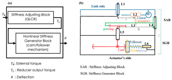
Figure 3.
Block representation of the V2SOM, (a) Two functional blocks of V2SOM (b) V2SOM kinematic scheme.
Figure 4 shows various simplified diagrams necessary to understand the functioning principle of this block. In Figure 4a, the cam follower system is in the resting position, meaning that the springs are relaxed and the cam’s applied torque about its rotation axis is . Applying a torque generates a deflection angle 𝛾 and the translation of the sliders supporting the followers, which results in the compression of the springs (Figure 3b).
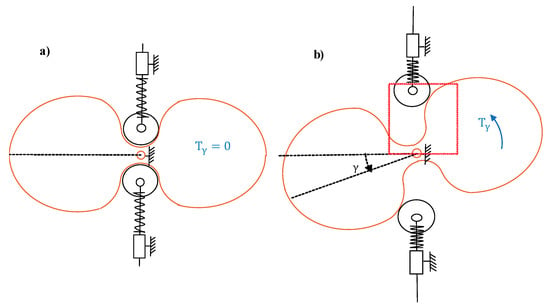
Figure 4.
Stiffness generator block: (a) at rest ( = 0); (b) at deflection ().
The stiffness adjusting block (SAB) acts as a reducer by using a gear ring system, which is considered to be made up of gear mechanisms commonly used to transform the rotary motion into either rotary or linear motion [28]. Furthermore, the SAB serves as a variable reducer thanks to the linear actuator M, which controls the distance r while driving the gears in a lever-like configuration. The reduction ratio of SAB is continuously tunable, allowing V2SOM to cope with the external load , where the link side makes a deflection angle relative to the actuator side.
Figure 5 shows the symmetrical two ring gears (in blue and green in Figure 5a) geared to a central spur gear (in red). These two ring gears are driven by a symmetrical double lever arm system via two rods (in yellow). These rods, which are part of the lever arm , as illustrated in Figure 4, slide freely along the pocket of the ring gear, creating the prismatic joint shown in Figure 5b. Adjusting the position of the rods along the lever arm via linear actuator M changes the transmission ratio of the lever arm system, and hence the reduction ratio of the SAB. The gears’ rotation induces a variation of the rods’ position along the pockets, which is characterized by the distance 𝑥 in Figure 5b.
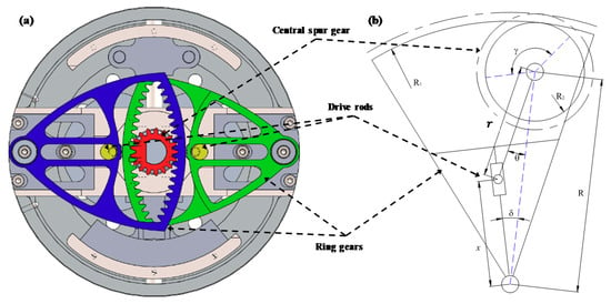
Figure 5.
Stiffness adjusting block (SAB) illustration of (a) cross section of CAD (computer aided design) model and (b) half scheme with a single ring gear.
The V2SOM CAD (computer aided design) model is presented in Figure 6. More details are given in the V2SOM patent [29,30]. Figure 6a shows the two blocks, the stiffness adjustable block and the generator block, with a zoomed-in view. Each block is depicted by additional views of their mechanical parts (Figure 6b–d) with correspondence to the kinematic sketch in Figure 3b. One can identify the linear actuators, the gearing, and cam follower system with its actuation side.
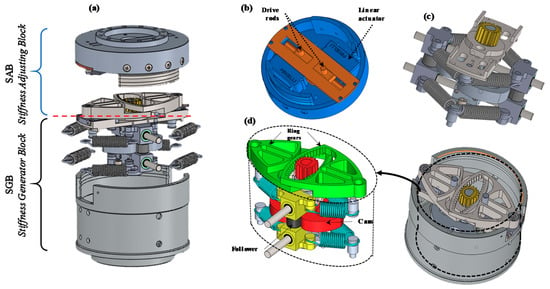
Figure 6.
The V2SOM prototype (a) Exploded view of V2SOM (b) CAD model of SAB (c) CAD model of the cam follower mechanism with springs (d) CAD model of SGB.
The V2SOM blocks, as shown in Figure 4, are connected rigidly to fulfill separate dedicated tasks:
- The SGB is characterized by the curve of the torque vs. deflection angle . This curve is obtained through the cam profile, the followers, and other design parameters. The basic torque curve leading to the torque characteristic of the V2SOM is depicted in Figure 6a. This basic curve is elaborated with a torque threshold equal to .
- The SAB is considered a quasi-linear continuous reducer (QLCR) and defined by its ratio expression given in Figure 6b. The ratio is a function of the NL (Nonlinear) factor, the deflection angle , and the reducer’s tuning parameter . The NL (Nonlinear) factor is linked to the SAB’s internal parameters and can be approximated with a constant when the deflection range is between and ; this process is discussed in the next section.
Figure 7c shows the V2SOM characteristics resulting from Figure 7a, with seven increasing reduction ratio settings (seven values of torque tuning). Thanks to the QLCR behavior of the SAB, the curves in Figure 7c follow a formula similar to Equation (1), with the specific tunable constant s and a deflection range.
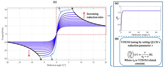
Figure 7.
(a) Example of V2SOM basic torque curve with (b) quasi-linear continuous reducer (QLCR); (c) illustration of the V2SOM torque characteristic with seven QLCR settings.
In general, V2SOM has two working modes, between which a transition smoothly takes place in the case of blunt shock, as illustrated in Figure 8. The normal working mode of the V2SOM is the one with linear region, mode (I), which allows the system to avoid a loss of control if the load exceeds the maximum. In case of a collision, mode (II), with the quasi-linear region, is activated. A high stiffness mode (I) is defined within the deflection range and the torque range . The value defines the torque in normal working conditions. Exceeding this torque value means that the shock absorbing mode is triggered, characterized by a low stiffness that leads to the torque threshold . The torque value, which limits the normal working mode of V2SOM, is an online tunable value. Adjusting this value allows us to cope with possible load variations due to the robot’s dynamics.
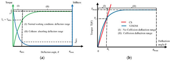
Figure 8.
(a) V2SOM working modes; (b) statically equivalent V2SOM and constant stiffness (CS) profiles.
2.3. Understanding Stiffness and Adjusting the Block’s Behavior
The QLCR behavior is exemplified in Figure 9, where two kinds of curves are shown:
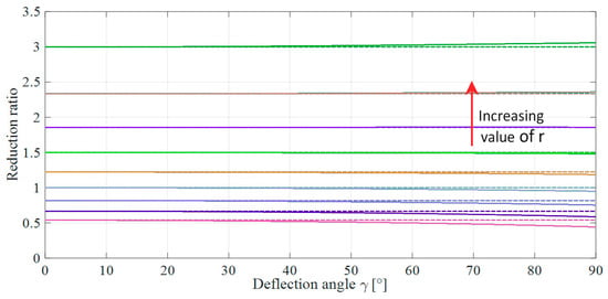
Figure 9.
Reduction ratio: QLCR in solid lines: and ideally equivalent reducer (IR) in dotted lines: .
- Solid curves represent the QLCR reduction ratio, multiplied by a constant C related to the mechanism’s parameters.
- Dotted line curves represent an ideally equivalent reducer (), where the reduction ratio is constant while the deflection angle changes. The following equation describes this ideal approximation:
Both curves present the same reduction ratio in the vicinity of zero deflection. This means that QLCR can be considered as an ideal tunable reducer near zero deflection (i.e., not during a collision scenario). Thereupon, QLCR can be tuned using Equation (2). When a collision takes place, the QLCR reduction ratio starts to diverge slightly from the corresponding curves. This slight change is not problematic because the function of V2SOM in this phase is to absorb shock energy rather than to precisely set a safety threshold.
At each torque vs. deflection curve of Figure 7 (i.e., for a given reduction ratio r), the stiffness passively varies from a high stiffness value near zero deflection to a practically null stiffness for which the torque attains its threshold; for example, see Figure 10b at the setting .
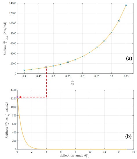
Figure 10.
(a) Stiffness variation range of the V2SOM; (b) stiffness vs. deflection at the setting .
As for the stiffness modulation in the vicinity of zero deflection angle , Figure 10a shows the variation range of the presented prototype. As can be seen, the V2SOM’s stiffness near zero deflection allows for a wide modulation range that varies from to for . From a theoretical viewpoint, the setting at gives an infinite stiffness value. However, practically, V2SOM’s stiffness is limited by the stiffness of its components. It should be mentioned that the main goal of the V2SOM stiffness profile is to provide a high stiffness in the smaller range to handle a robot’s dynamics upon collision (i.e., when it exceeds the tunable threshold, the stiffness drops rapidly and passively to guarantee safe collision absorption).
3. Safety Criteria: V2SOM vs. Constant Stiffness
The safety of pHRI is quite problematic in terms of quantification as well as its application to the whole body. However, the abbreviated injury scale (AIS) [31] presents a simple mapping system, from a medical perspective, of different safety criteria, with a unified scale with values ranging from 0 (no injury) to 6 (severe injury or death).
3.1. Safety Criteria
To achieve safe HR collaboration, a level 1 in AIS must be respected. In this work, we consider 0 in AIS as an ergonomic threshold for making human-friendly cobots. ISO/TS-15066 and Newman [32] adopted the most widely considered safety criteria, namely:
- G: The generalized model for brain injury threshold was introduced by Newman (see [33,34]). This index considers both the direction of the impact and the angular accelerations. The G index is valid for 50% of probability of AIS ≥ 3, which does not help to evaluate safe and human-friendly HR collisions, where AIS ≤ 1.
- NIR (new safety index): This index is quite similar to the HIC formulation. While HIC is generic, NIR is specific to the robot’s technical data, which are provided in the manufacturer catalogs [34,35]. In our case, HIC is used to include the cover’s effect on safety.
- HIC quantifies high accelerations of the brain (concussion) during blunt shocks even for a short amount of time; for example, less than 15 ms can cause severe, irreversible health effects [35].
- ImpF (also known as contact force) is quite interesting as it can be applied to the whole body. This value is considered for a specific contact surface with a minimum area.
- Compression criterion (CC) reflects the damaging effect of human–robot (HR) collisions by means of deformation depth, mainly adopted for the naturally compliant chest and belly regions.
Regarding the data in Table 3, the head region is the most critical part of the human body compared to the trunk region, which is more naturally resilient, as indicated by the CC column. The CC criterion is not relevant to the head region as the skull is quite rigid. In contrast, HIC and ImpF are considered for their complementary aspect of HR shock evaluation. HIC is suitable for internal damage evaluation as it quantifies dangerous brain concussions. ImpF is suitable for external damage evaluation. Note that the HIC is only valid in the case of nonclamped head collision scenarios. On the other hand, a constrained head is a dangerous scenario, as shown by Heinzmann and Zelinsky [8]. Thus, a collaborative workspace should be designed, as note ISO/TS15066 permits, in such a way that free head motion is not compromised; this is the first step to guaranteeing safe pHRI.

Table 3.
Safety criteria thresholds for most critical body regions from ISO/TS15066 and Payne [31]. ImpF = impact force; AIS = abbreviated injury scale; CC = compression criterion; HIC = head injury criterion.
3.2. Human–Robot Collision Model
The human head is the most critical body region when dealing with the safety problems of pHRI. Indeed, some previous works [13,14] have investigated this issue. Furthermore, they proceeded with theoretical modeling of dummy head hardware in crash tests. The resulting model (see Figure 11) has been well-tuned experimentally and validated.
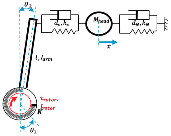
Figure 11.
Mechanical model of dummy head hardware collision against a robot arm. Simulation results of human-robot collision.
The model in Figure 11 is parameterized according to Wolf et al. [14], with:
- Neck viscoelastic parameters , .
- Head’s mass and linear displacement x.
- The contact surface viscoelastic parameters , .
- Robot arm contact position l and inertia .
- Rotor inertia , torque , and angular position .
- VSM’s stiffness and angular deflection .
The collision model allows us to evaluate both ImpF and HIC. The first criterion is directly deduced from the simulation data as the maximum value of the contact force. HIC is evaluated by solving the following optimization problem:
where is the head acceleration value at instant t.
In the next sections, to compare between V2SOM and constant stiffness (CS), a VSM is carried out via a simulation of the HR collision model in the Matlab/Simulink platform. Here, the CS value is set so that the two profiles match at a torque value of , as shown in Figure 8. This torque value defines the deflection range of the normal operational mode for the V2SOM, after which the shock-absorbing mode is considered to be triggered.
The following simulations are meant to highlight V2SOM’s inertia and torque decoupling capacities in comparison to a statistically equivalent CS-based VSM. These capacities represent the robust passive tackling of a HR collision in the fast and critical phase before the collision detection and reaction take place (e.g., within a range of 15 ms), as quantified via the HIC. These simulations were carried out using parametrization of Table 4 to evaluate both safety criteria (HIC and ImpF).

Table 4.
Simulation parameters.
3.2.1. Inertia Decoupling
Figure 12 shows that V2SOM presents more than 80% gains on an HIC basis compared to CS. On the other hand, a gain of 10%–40% is noticed for ImpF curves. and are steady for a large range of rotor inertia. This property leads us to conclude that V2SOM presents a high inertia decoupling capability compared to a CS-based VSM. Ideally, this characteristic means that the human body, in the case of a HR shock, is subject to only arm-side inertia rather than the heavy resulting arm and rotor inertia.

Figure 12.
impact on safety criteria, (a) HIC and (b) ImpF, for both V2SOM and CS characteristics.
As previously shown by Haddadin et al. [7], lower values of the mobile mass allow for higher velocities to maintain the same safety level. By considering the V2SOM inertia decoupling capability in addition to Haddadin’s results, the proposed design allows for better dynamic performance of the cobot without overreaching the safety thresholds.
3.2.2. Torque Decoupling
V2SOM presents a quasi-constant response that can be observed in Figure 13. The large change in motor-applied torque, , leads to a significant variation in the HIC and ImpF values of CS-based VSM in comparison with V2SOM, which maintains the same values. The significant variation of 10%–40% in ImpF can be improved with a customized contact surface of the robot arm. However, HIC cannot be reduced and it will be difficult to attenuate the 80% gap between the two responses (Figure 13a). The benefit of V2SOM use, in terms of a reduction in concussions, is visible through HIC mitigation vs. CS use.

Figure 13.
impact on safety criteria, (a) HIC and (b) ImpF, for both V2SOM and CS characteristics.
4. Experimental Validation of V2SOM
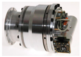
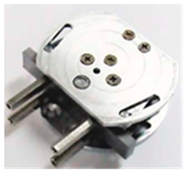
In this section a static characterization of the first V2SOM prototype and a preliminary HR collision testing are presented. Figure 14 shows the developed prototype, which is a cylinder 92 mm in diameter and 78 mm in height that weighs about 970 g. A lighter and more compact version is under development, along with a safety-oriented control strategy using V2SOM.
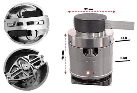
Figure 14.
V2SOM first prototype.
4.1. Quasi-Static Characterization of V2SOM
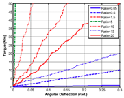
Figure 15 shows the V2SOM characteristics in terms of torque vs. deflection for different settings of the tuning parameter ranging from 16.6 to 26.6 mm. Quasi-static characterization means the load is applied at a slow rate like a static load [11]. The solid curves represent the theoretical curves, while the experimental curves are represented by dotted lines. The former displays relatively constant torque thresholds, proving that the cam correction brings V2SOM behavior near to its ideal form. The experimental curves deviate slightly from the theoretical ones. This error will be mitigated in upcoming versions by measures such as friction sources analysis and in-depth study of the mechanical parts’ deformation. In addition, some parts will be enhanced, such as improving the stiffness profile time change by opting for faster linear actuators. For more details about this prototype, see the table in Appendix A of the mechanical and electrical specifications, which are written according to the recommendations of Grioli et al. [3].
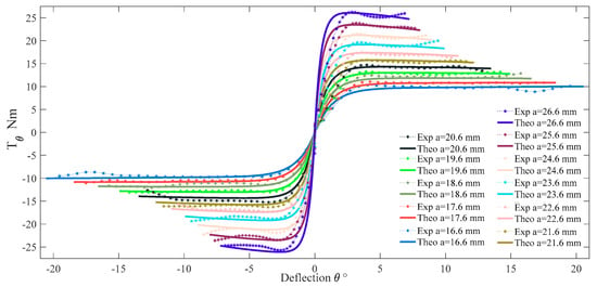
Figure 15.
V2SOM characteristics: theoretical (in solid lines) and experimental (in dotted lines) with the 11 different SAB settings.
4.2. Preliminary HR Collision Tests
Currently, a safety-oriented control strategy is in ongoing development, wherein a V2SOM-based cobot functions under preemptive safety conditions in terms of joints’ angular velocities. For this purpose, an optimization problem that maximizes the safely reachable angular velocities was formulated by taking into account the actual robot configuration. These constraints result from the simulation and are stored as lookup tables for real-time access.
In this paper, a simple example of tackling a collision with a human subject using V2SOM is demonstrated. The experimental setup is shown in Figure 16.
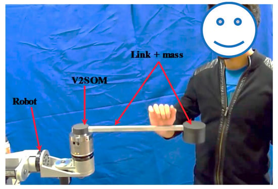
Figure 16.
Experimental setup.
In Figure 17, the results of two collision tests are presented. In the first test (Figure 17a,b), the link’s inertia is with an impact velocity of 90°/s. In the second test, (Figure 17c,d), the link’s inertia is with an impact velocity of 32°/s. In both cases, V2SOM presents small deflections corresponding to the normal working conditions range (range I; see Figure 8). Upon collision, the safety threshold is exceeded and V2SOM warns of the collision by sending a collision detection message via a CAN (Controller Area Network) bus to the robot’s main controller. Hence the robot, through its controller, stops the joint rotation. In the in-between phase (range I and range II in Figure 8), V2SOM passively absorbs the shock’s kinetic energy. The elastic end stroke of the V2SOM should not be reached either by a V2SOM maximum storable elastic energy or by a possible slow control reaction. For this reason, both previous features are considered in developing the safety-oriented control strategy.
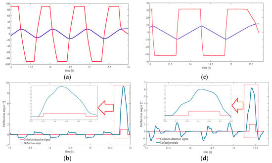
Figure 17.
Results of experimental collision tests: (a) angular velocity and position of the link in the first test; (b) V2SOM deflection angle in the first test; (c) angular velocity and position of the link in the second test; (d) V2SOM deflection angle in the second test.
The time elapsed between the collision detection (exiting deflection range I) and returning is 180 ms in the first test and 140 ms in the second test.
These illustrative tests are meant first to show the inertia decoupling and torque decoupling capability of the V2SOM and then to shed light on the problem of a collision control strategy that is specifically designed to benefit from the V2SOM properties (e.g., inertia decoupling capacity). This problem is the subject of our upcoming work (for a general review of HR collision control see [4]).
5. Discussion
The simulation allowed us to cover a large range of inertia as well as torque. Based on the obtained results, we can conclude that V2SOM presents a high inertia decoupling capability, which is correlated with the results obtained during the experimentation. Safe physical human–robot interaction is ensured in the case of collision due to the presence of two continuously linked functional modes of V2SOM: high and low stiffness modes. Future work will be focused on the evaluation of the dynamic performance of robots using V2SOM as a way to cope with possible limitations.
6. Conclusions and Future Work
In this paper, we presented V2SOM as the basis of a human-friendly cobot in compliance with safety level 1 on the AIS. V2SOM displays two complementary working modes:
- In normal working conditions, characterized by high stiffness, the proposed mechanism limits the storable elastic energy that increases the absorbed kinetic energy in case of a sudden HR shock. Moreover, this high stiffness limits the elastic deflection to near zero, which eases the robot control.
- In the case of a blunt HR impact, V2SOM stiffness promptly decreases, allowing fast absorption of the collision energy.
From a safety perspective, as shown via the collision simulations, two complementary safety criteria were adopted for internal and external damage evaluation of the human body. Based on these two criteria, HIC and ImpF, important improvements were observed for the V2SOM profile in contrast to an equivalent CS profile. Especially in terms of brain concussion quantification, HIC was reduced by over 70% relative to the results of the CS profile. Moreover, V2SOM presented a high inertia decoupling capacity (i.e., large variation in rotor-side inertia slightly impacts the evaluation of safety on a HIC basis).
The experimental implementation, through the HR collision tests, shows the decoupling capacities of V2SOM. In case of collision, the deflection is detected, and the kinetic energy absorbed, which guarantees safe physical human–robot interaction.
Thus, the present work is focused on an illustrative case study of a one degree-of-freedom robot arm. In future work, different HR collision scenarios will be investigated by considering a generic multi-degrees of freedom (DoFs) robot with V2SOM joints, its dynamics, and the impact location on the robot arm.
7. Patents
WO 2019/043068 A1—7 March 2019: “Mechanical Device with Passive Compliance for Transmitting Rotational Movement,” M. Arsicault, Y. Ayoubi, M.A Laribi, S. Zeghloul, and F. Courrèges.
Author Contributions
Conceptualization, Y.A. and M.A.L.; validation, Y.A. and M.A.; designed the experiments and wrote the paper, Y.A., M.A.L., and M.A.; supervised the research work, M.A.L. and S.Z. All authors have read and agreed to the published version of the manuscript.
Funding
This research was funded by ANR (Agence Nationale de la Recherche), grant number ANR-14-CE27-0016, Project: Safety Intelligent Sensor for Cobot (SISCob).
Acknowledgments
This work was supported by the French National Research Agency, convention ANR-14-CE27-0016. This work was sponsored by the French government research program “Investissements d’avenir” through the Robotex Equipment of Excellence (ANR-10-EQPX-44).
Conflicts of Interest
The authors declare no conflicts of interest.
The authors declare no conflicts of interest
Appendix A

Table A1.
V2SOM mechanical and electrical specifications.
Table A1.
V2SOM mechanical and electrical specifications.
| Mechanical | ||||
| 1 | Lowest Safety Threshold Torque | (Nm) | 9.7 | |
| 2 | Safety Threshold Variation Time (from nominal level to completely stiff state) | With/Without Load (prone improvement) | (s) | 1.6 |
| 3 | Maximum Stiffness | (Nm/rad) | ||
| 4 | Minimum Stiffness | (Nm/rad) | ~0 | |
| 5 | Maximum Elastic Energy | (J) | 2.98 | |
| 6 | Maximum Deflection | With Maximum Safety Threshold | (°) | 0 |
| With Minimum Safety Threshold | (°) | 20 | ||
| 7 | Active Rotation Angle | (°) | ||
| 8 | Angular Resolution | (°) | 0.0313 | |
| 9 | Weight | (Kg) | 0.970 | |
| Electrical | ||||
| 10 | Nominal Voltage | (V) | 12 | |
| 11 | Nominal Current | (A) | 0.010 | |
| 12 | Maximum Current | (A) | 0.500 | |
| Control | ||||
| 13 | Voltage Supply | (V) | 12 | |
| 14 | Nominal Current | (A) | 0.105 | |
| 15 | I/O Protocol | CAN (Controller Area Network) (1 Mbit/s) | ||
References
- Lu, Y. Industry 4.0: A survey on technologies, applications and open research issues. J. Ind. Inf. Integr. 2017, 6, 1–10. [Google Scholar] [CrossRef]
- Tobe, F. Why Co-Bots Will Be a Huge Innovation and Growth Driver for Robotics Industry. Available online: https://www.aitrends.com/robotics/why-co-bots-will-be-a-huge-innovation-and-growth-driver-for-robotics-industry/ (accessed on 1 January 2016).
- Grioli, G.; Wolf, S.; Garabini, M.; Catalano, M.G.; Burdet, E.; Caldwell, D.; Carloni, R.; Friedl, W.; Grebenstein, M.; Laffranchi, M.; et al. Variable stiffness actuators: The user’s point of view. Int. J. Robot. Res. 2015, 34, 727–743. [Google Scholar] [CrossRef]
- Haddadin, S.; De Luca, A.; Albu-Schaffer, A. Robot Collisions: A Survey on Detection, Isolation, and Identification. IEEE Trans. Robot. 2017, 33, 1292–1312. [Google Scholar] [CrossRef]
- Zinn, M.; Khatib, O.; Roth, B.; Salisbury, J. Playing it safe. IEEE Robot. Autom. Mag. 2004, 11, 12–21. [Google Scholar] [CrossRef]
- Jianbin, H.; Zongwu, X.; Minghe, J.; Zainan, J.; Hong, L. Adaptive Impedance-controlled Manipulator Based on Collision Detection. Chin. J. Aeronaut. 2009, 22, 105–112. [Google Scholar] [CrossRef]
- Haddadin, S.; Albu-Schaffer, A.; Hirzinger, G. The role of the robot mass and velocity in physical human-robot interaction—Part I: Non-constrained blunt impacts. In Proceedings of the IEEE International Conference on Robotics and Automation, Nice, France, 22–26 September 2008. [Google Scholar]
- Heinzmann, J.; Zelinsky, A. Quantitative Safety Guarantees for Physical Human-Robot Interaction. Int. J. Robot. Res. 2003, 22, 479–504. [Google Scholar] [CrossRef]
- Haddadin, S.; Albu-Schaffer, A.; Frommberger, M.; Hirzinger, G. The role of the robot mass and velocity in physical human-robot interaction—Part II: Constrained blunt impacts. In Proceedings of the IEEE International Conference on Robotics and Automation, Nice, France, 19 May 2008. [Google Scholar]
- Pratt, G.A.; Williamson, M.M. Series elastic actuators. In Proceedings of the IEEE/RSJ International Conference on Intelligent Robots and Systems. Human Robot Interaction and Cooperative Robots, Pittsburgh, PA, USA, 5–9 August 1995. [Google Scholar]
- Corral, E.; García, M.; Castejon, C.; Meneses, J.; Gismeros, R. Dynamic Modeling of the Dissipative Contact and Friction Forces of a Passive Biped-Walking Robot. Appl. Sci. 2020, 10, 2342. [Google Scholar] [CrossRef]
- Mathijssen, G.; Cherelle, P.; Lefeber, D.; VanderBorght, B. Concept of a Series-Parallel Elastic Actuator for a Powered Transtibial Prosthesis. Actuators 2013, 2, 59–73. [Google Scholar] [CrossRef]
- Zinn, M.; Roth, B.; Khatib, O.; Salisbury, J.K. A New Actuation Approach for Human Friendly Robot Design. Int. J. Rob. Res. 2004, 23, 379–398. [Google Scholar] [CrossRef]
- Wolf, S.; Grioli, G.; Eiberger, O.; Friedl, W.; Grebenstein, M.; Hoppner, H.; Burdet, E.; Caldwell, D.G.; Carloni, R.; Catalano, M.G.; et al. Variable Stiffness Actuators: Review on Design and Components. IEEE/ASME Trans. Mechatron. 2015, 21, 2418–2430. [Google Scholar] [CrossRef]
- López-Martínez, J.; García-Vallejo, D.; Giménez-Fernández, A.; Torres-Moreno, J.L. A Flexible Multibody Model of a Safety Robot Arm for Experimental Validation and Analysis of Design Parameters. J. Comput. Nonlinear Dyn. 2013, 9, 011003. [Google Scholar] [CrossRef]
- Hyun, D.; Yang, H.S.; Park, J.; Shim, Y. Variable stiffness mechanism for human-friendly robots. Mech. Mach. Theory 2010, 45, 880–897. [Google Scholar] [CrossRef]
- Tagliamonte, N.L.; Sergi, F.; Accoto, D.; Carpino, G.; Guglielmelli, E. Double actuation architectures for rendering variable impedance in compliant robots: A review. Mechatronics 2012, 22, 1187–1203. [Google Scholar] [CrossRef]
- VanderBorght, B.; Albu-Schaeffer, A.; Bicchi, A.; Burdet, E.; Caldwell, D.; Carloni, R.; Catalano, M.G.; Eiberger, O.; Friedl, W.; Ganesh, G.; et al. Variable impedance actuators: A review. Robot. Auton. Syst. 2013, 61, 1601–1614. [Google Scholar] [CrossRef]
- Jafari, A.; Tsagarakis, N.G.; Caldwell, D. AwAS-II: A new Actuator with Adjustable Stiffness based on the novel principle of adaptable pivot point and variable lever ratio. In Proceedings of the IEEE International Conference on Robotics and Automation, Shanghai, China, 9–13 May 2011. [Google Scholar]
- Wolf, S.; Eiberger, O.; Hirzinger, G. The DLR FSJ: Energy based design of a variable stiffness joint. In Proceedings of the 2011 IEEE International Conference on Robotics and Automation, Shanghai, China, 9–13 May 2011. [Google Scholar]
- Eiberger, O.; Haddadin, S.; Weiß, M.; Albu-Schaffer, A.; Hirzinger, G. On joint design with intrinsic variable compliance: Derivation of the DLR QA-Joint. In Proceedings of the 2010 IEEE International Conference on Robotics and Automation, Anchorage, Alaska, 3 May 2010. [Google Scholar]
- Friedl, W.; Chalon, M.; Reinecke, J.; Grebenstein, M. FAS A flexible antagonistic spring element for a high performance over. In Proceedings of the 2011 IEEE/RSJ International Conference on Intelligent Robots and Systems, San Francisco, CA, USA, 25–30 September 2011. [Google Scholar]
- Ayoubi, Y.; Laribi, M.A.; Courreges, F.; Zeghloul, S.; Arsicault, M. A complete methodology to design a safety mechanism for prismatic joint implementation. In Proceedings of the 2016 IEEE/RSJ International Conference on Intelligent Robots and Systems (IROS), Daejeon, Korea, 9–14 October 2016. [Google Scholar]
- Lan, N.; Crago, P.E. Optimal control of antagonistic muscle stiffness during voluntary movements. Boil. Cybern. 1994, 71, 123–135. [Google Scholar] [CrossRef] [PubMed]
- Park, J.-J.; Song, J.-B. A Nonlinear Stiffness Safe Joint Mechanism Design for Human Robot Interaction. J. Mech. Des. 2010, 132, 061005. [Google Scholar] [CrossRef]
- Park, J.-J.; Lee, Y.-J.; Song, J.-B.; Kim, H.-S. Safe joint mechanism based on nonlinear stiffness for safe human-robot collision. In Proceedings of the 2008 IEEE International Conference on Robotics and Automation, Pasadena, CA, USA, 19–23 May 2008. [Google Scholar]
- Petit, F.; Friedl, W.; Höppner, H.; Grebenstein, M. Analysis and Synthesis of the Bidirectional Antagonistic Variable Stiffness Mechanism. IEEE/ASME Trans. Mechatron. 2014, 20, 684–695. [Google Scholar] [CrossRef]
- Meneses, J.; Garcia-Prada, J.C.; Castejon, C.; Rubio, H.; Corral, E. The kinematics of the rotary into helical gear transmission. Mech. Mach. Theory 2017, 108, 110–122. [Google Scholar] [CrossRef]
- Ayoubi, Y.; Laribi, M.A.; Arsicault, M.; Zeghloul, S.; Courreges, F. Mechanical Device with Variable Compliance for Rotary Motion Transmission. WO 2019/043068 A1, 7 March 2019. [Google Scholar]
- Ayoubi, Y.; Laribi, M.A.; Zeghloul, S.; Arsicault, M. Design of V2SOM: The safety mechanism for cobot’s rotary joints. In IFToMM Symposium on Mechanism Design for Robotics; Springer: Cham, Switzerland, 2018; pp. 147–157. [Google Scholar]
- Payne, D.A.R.; Patel, S. Levels Of Consciousness In Relation To Head Injury Criteria. 2001. Available online: http://www.eurailsafe.net/subsites/operas/HTML/appendix/Table13.htm (accessed on 1 January 2017).
- HIC Tolerance Levels Correlated To Brain Injury. Available online: http://www.eurailsafe.net/subsites/operas/HTML/appendix/Table14.htm (accessed on 3 June 2015).
- Newman, J.A. A generalized acceleration model for brain injury threshold (GAMBIT). In Proceedings of the International IRCOBI Conference, Zurich, Switzerland, 2–4 September 1986. [Google Scholar]
- Alén-Cordero, C.; Carbone, G.; Ceccarelli, M.; Echávarri, J.; Muñoz, J.L. Experimental tests in human–robot collision evaluation and characterization of a new safety index for robot operation. Mech. Mach. Theory 2014, 80, 184–199. [Google Scholar] [CrossRef]
- Gao, D.; Wampler, C.W. Assessing the Danger of Robot Impact. IEEE Robot. Autom. Mag. 2009, 16, 71–74. [Google Scholar] [CrossRef]
© 2020 by the authors. Licensee MDPI, Basel, Switzerland. This article is an open access article distributed under the terms and conditions of the Creative Commons Attribution (CC BY) license (http://creativecommons.org/licenses/by/4.0/).
