1. Introduction
The piston ring–cylinder liner (PRCL) assembly contributes to 20% to 50% of the total mechanical energy loss of internal combustion engine (ICE) [
1]. In passenger cars, approximately 4%–7.5% of fuel energy is used to overcome the frictional losses by the piston assembly, and the oil control ring alone corresponds to 0.23% to 2.8% of the fuel energy in the diesel engine [
2]. Piston rings need to be conformed to the bore shape to prevent lubricant oil consumption and corresponding emission of particular and hydrocarbons. However, high piston ring tension leads to increased friction losses, which means more fuel consumption and greenhouse gas (GHG) emissions [
3,
4]. This implies that decreasing the friction in this contact without altering the sealing function can both increase the efficiency of the engine and reduce GHG emissions, which is a major challenge for the automotive industry [
5,
6].
Many researchers have discussed the tribological performance of the PRCL friction pair. Most of them have focused on the honing texture, roughness, and orientation [
7,
8,
9,
10,
11]. Only few published works have discussed the enhancement of the PRCL conformation through the increase of the shape accuracy in the fired state. Increasing the roundness of the deformed liner in the fired state provides a significant opportunity for improving the PRCL performance [
12,
13]. The authors of [
14] studied the performance of initially noncircular liners numerically. In this study, it was shown that an engine with noncircular liners in the cold state can increase the roundness of the liners in its fired state significantly. The authors of [
15] studied the effects of liner bore shape on the friction using a floating liner research engine. They found that using a larger bore diameter in the bottom of the liner decreased the friction.
There are many reasons which cause the liner to deform from its ideal circular shape. This includes manufacturing inaccuracies, the assembly process, thermal expansion variations between different engine components, temperature gradients during the fired state, and mechanical load during fired operations [
16,
17]. More than 85% of the accumulated deformation in the liner is referred to the operational mechanical and thermal loads [
13]. The shape, the way, and the value of this deformation, in both longitudinal and radial directions, must have a great influence on any design improvement. Hence, the prediction of those deformation factors is important to enhance engine performance.
The rate of radial liner deformation along the longitudinal direction is influenced by the uneven distribution of combustion heat to the cylinder. The cylinder wall temperature increases toward the top section resulting in increased liner diameter in the upper part of the liner. As the piston diameter increases as well, eventually, the lower part causes more friction [
18]. This problem can be solved by applying a specific honing profile on the liner, offering a greater liner diameter in the lower part of the liner. This technology is already implemented by some manufacturers [
12,
18,
19]. However, detailed work on the quantification of the parallelism and straightness of the liner in the fired state has not been published so far. The present article describes a methodology to analyze the uneven deformation of the liner between the cold and a hot state with numerical methods.
The aim of this article was to find a defined methodology to reduce the engine friction and achieve better PRCL conformation through increasing the liner’s straightness, roundness, and parallelism during the fired operation state. To reach that, a tapered bore liner in the cold state should be used. The main hypothesis in this work is that a suitable formed conical liner will be deformed to a more cylindrical shape in the fired state, such that the friction will decrease. Furthermore, mixing the conical shape with elliptical cross sections can be supposed to enhance the roundness, parallelism, and straightness of the liner.
To investigate that, the deformation model was first validated through the comparison with experiments for a defined gasoline engine. Next, the local deformation of the liner was simulated for the originally cylindrical liner with circular cross sections for an operation condition with predefined thermal loads in the different regions of the liner, as can be seen realistic for an operating engine. In the next step, the local deformation was subtracted from the originally cylindrical liner shape so that the liner had a conical shape in the cold state. Moreover, the cross sections were taken here in predefined noncircular shape. With this shaped liner, the deformations were calculated for the assumed hot conditions, and the resulting shape was investigated for the fired operation conditions.
The main contribution of this article is to provide a quantitative study for the deformation and the deformation trends of honed liners. In this study, the geometrical aspects of honed liners were regarded. For that, quantitative parameters like straightness, roundness, and parallelism were introduced. To date, a combined conical-elliptical shaped liner has not been published.
2. Theoretical Background
The cylinder liner deformation can be represented by a Fourier series [
20]. The deviation Δ
R of the liner bore from the perfect circular shape can be written as:
where
are the Fourier’s coefficients,
is the angular position, and
is the deformation order. For each
nth order, the maximum bore deformation
and the phase angle
can be calculated with
Using the harmonic series, the Δ
R can be rewritten as:
Different deformation orders describe different distortion patterns. The zeroth order describes the round bore, the first order describes the eccentric bore, the second order describes the oval bore, third order describes the three-lobe-shaped bore, and the fourth order describes the four-lobe-shaped bore. Generally, the first four deformation orders dominate the total liner deformation, while the higher orders deformations are commonly neglected [
13].
3. Physical and Computational Model
For the simulation of the liner deformation, the complex three-dimensional thermal effects, as well as the local stresses and strains, have to be regarded. This can be done with Finite Element Methods (FEM) [
21]. The main challenge for FEM is the computational requirement and capacity, namely computational power, memory, and computational time. Therefore, it is important to work with sufficiently simple yet accurate models. The current study was done with the ANSYS mechanical software, which is able to study liner deformation [
22,
23,
24,
25,
26]. It is attractive due to its capability of handling dynamic, thermal, material, geometric, and contact nonlinearities in the finite element model.
The simulated engine in this work was based on a NISSAN CA18 gasoline engine, which had a piston stroke of 83.6 mm, cylinder bore of 83 mm, and total displacement of 1809 cm
3. The liner thickness was 1.6 mm, with a clearance of 80 μm from the engine block. More details about this engine dimensions and specifications have been described by the author of [
27]. The cylinder block and the cylinder liner were made of cast iron, while the cylinder head was made of an aluminum alloy. The physical material properties for the grey cast iron are shown in
Table 1. The deformation of this cylinder liner was measured at 4000 rpm under full load [
25]. The measured temperature at this operation points varied between 123 °C to 185 °C at the engine block and between 150 °C to 197 °C at the cylinder liner. The coolant temperature was 80 °C, and the used bolt pretension was 80,000 N. The top deck was restrained from the movement in the axial direction. Further details about the physical model have been described by the authors of [
14].
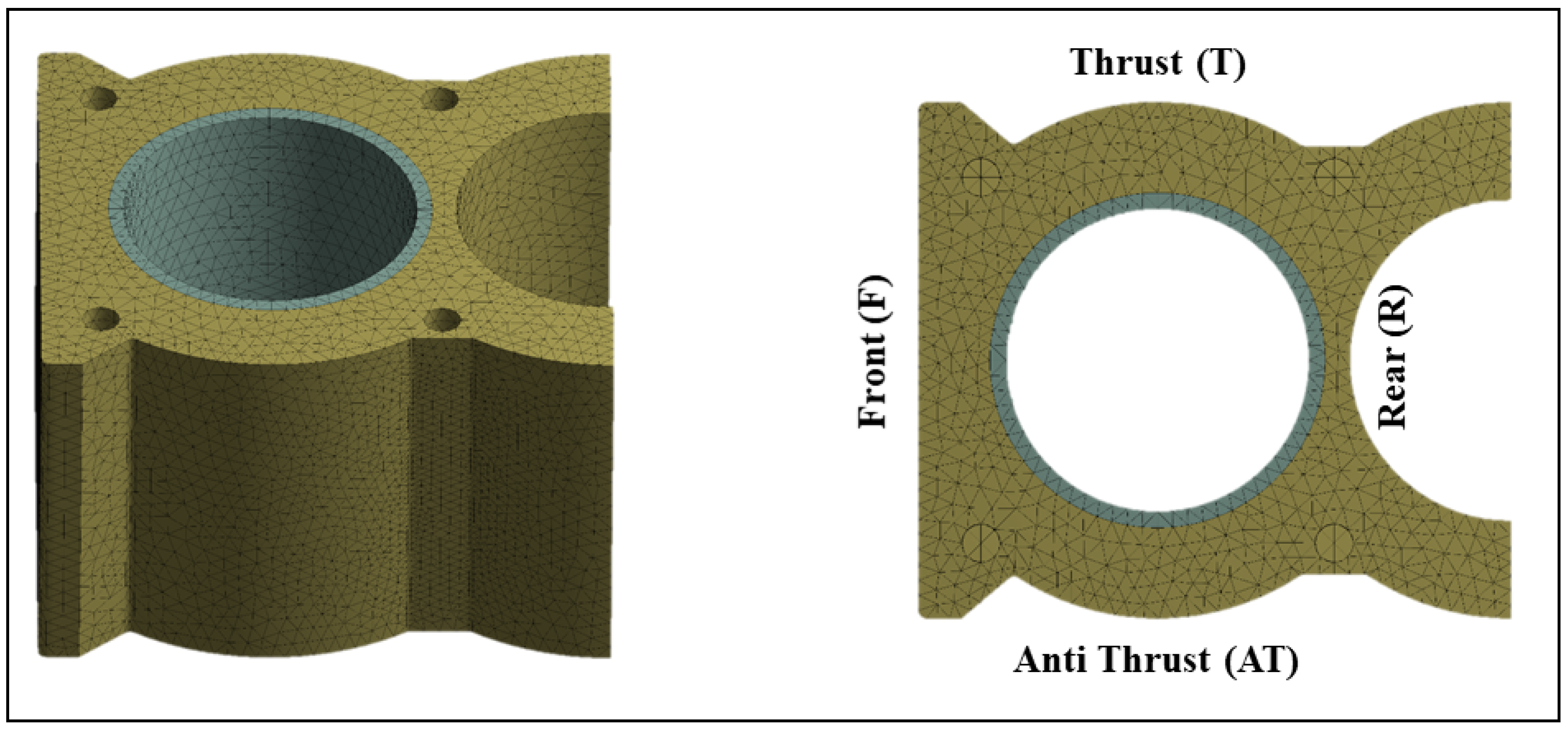
The numerical study was done on the terminal cylinder located at the end of the four-cylinder engine. The deformation of the terminal cylinder is different from the other intermediate cylinders due to uneven supply of the combustion heat in the front-rear direction. This leads to a third-order deformation pattern for the terminal cylinder in addition to the first-, second-, and fourth-order deformations that also appear in the intermediate cylinders. One and a half cylinders were simulated to include the effects of the thermal load from the adjacent cylinder and the surrounding (see
Figure 1). The simulated deformations were found to be in the range of up to 30 µm for the fired conditions. Both the trends and the values of the deformations have good agreement with experimental data described by the authors of [
25]. The detailed model configuration, boundary conditions, temperature distributions, mesh properties, grid independence test, circumferential position dependent deformation, and model validation have been explained by the authors of [
14].
4. Conical Liners
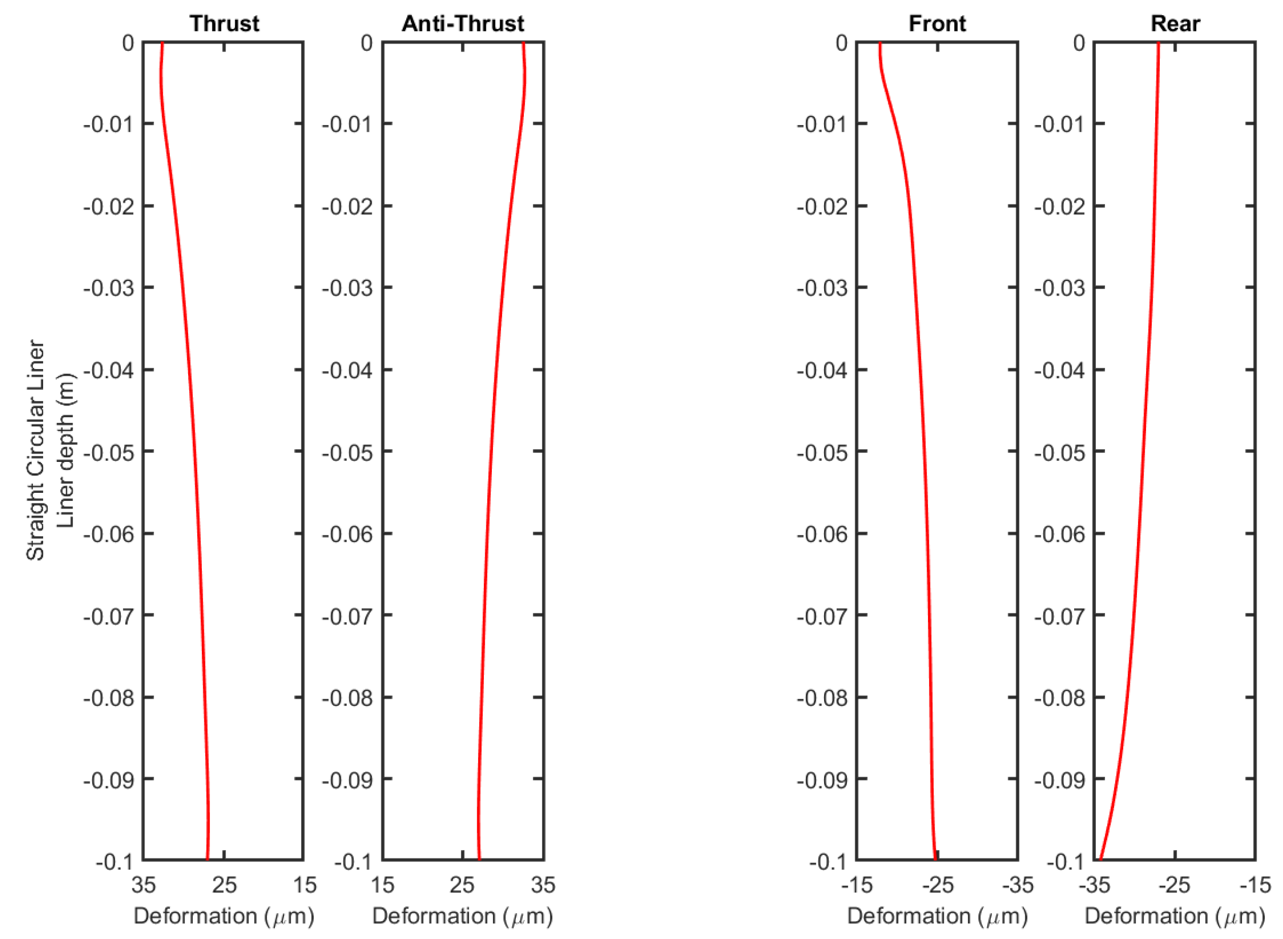
The selection of the tapering angle for the conical liner was based on reversing the angle resulted from the cylindrical liner.
Figure 2 shows the resulting bore deformation for the circular liner on the thrust, antithrust, front, and rear sides. The figure shows the deformation in a strongly exaggerated representation to highlight the differences between the upper and lower part deformations. It is noticeable that this difference varies from one side to another. The upper part is always more deformed than the lower part. The difference of the deformation is about 5 μm on the thrust and antithrust sides 7 μm on the front and rear sides. For the setup of an optimized liner, a conical shaped liner was assumed for the cold state. It was formed with 5-μm increments of the lower radius (see
Figure 3). This design is compatible with the generally known shapes for noncylindrical liners used by some manufacturers [
18,
19]. For the sake of simplicity, the design proposed in this work was based on one fixed operation point. In later applications, an optimal inclination design should be determined on the basis of a statistical analysis for different operation points of the engine.
Figure 3 also shows the cross section in the top plane of the conical liner. Two designs were investigated here. Commonly, the cross section has a circular form. In a preceding work [
14], it was shown that an elliptical liner cross section in the cold state can reduce the roundness error in the fired state by more than 75% for the terminal cylinder in four-cylinder gasoline engine due to the inhomogeneous thermal conditions. It was found that the deformation of a circular liner leads to a nearly elliptical shape in the fired state, while an initially elliptic liner with opposite ellipticity in the cold state deforms to an almost circular shape in the fired state. This does not affect the piston shape, since the amount of ellipticity is small and can be absorbed by the piston rings in the cold state. Furthermore, it can be assumed that the piston itself keeps its circular shape in the fired state due to its geometry.
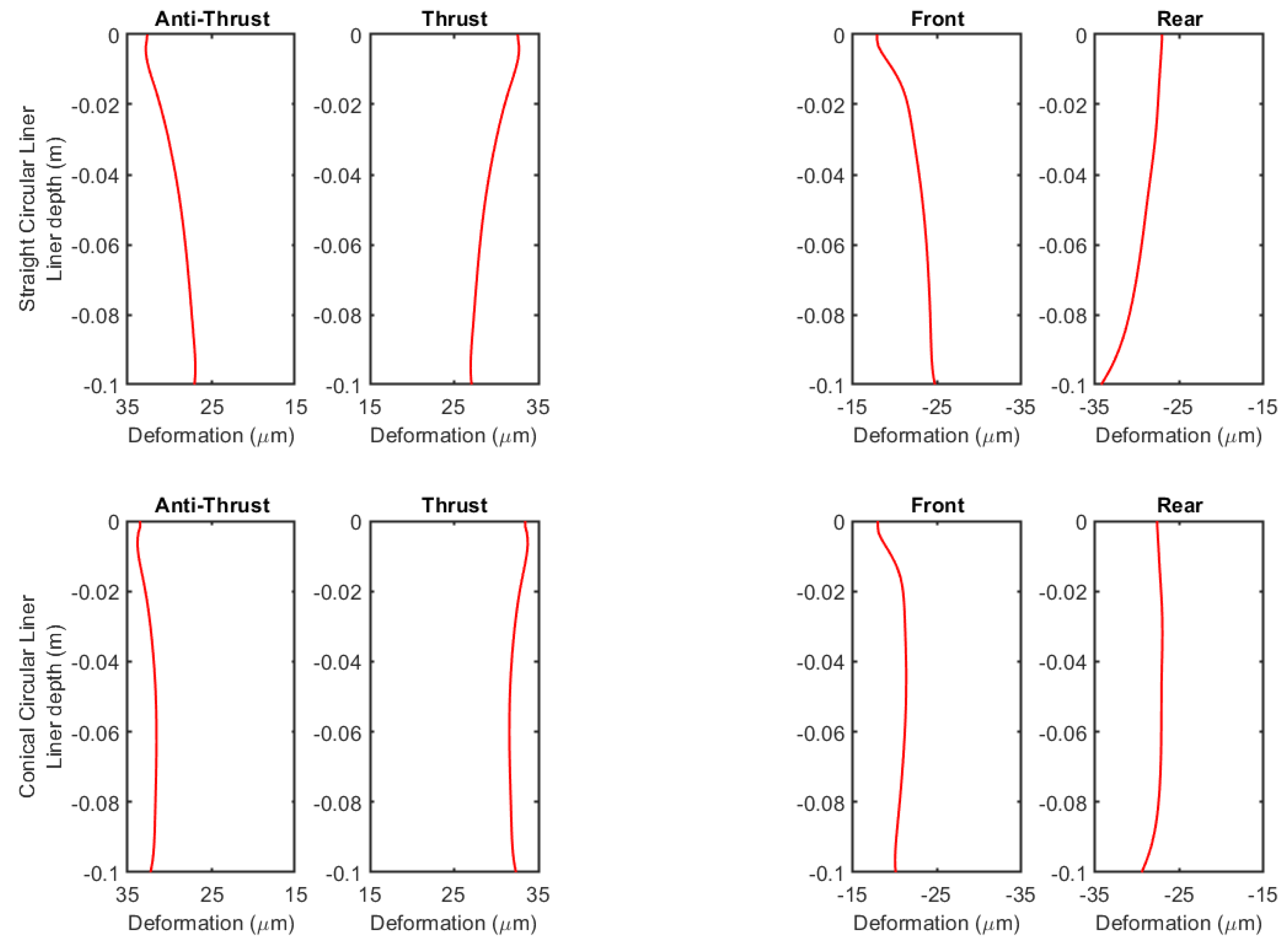
The deformation of both the conical circular and the conical elliptical liners in the cold state were simulated at the same operational conditions (4000 rpm at full load). The results for the bore deformation for circular and elliptical conical liners are presented in
Figure 4 and
Figure 5. For comparison, the figures also show the deformations of the initially straight wall liners, being either circular (
Figure 4) or elliptical (
Figure 5). The comparison between the straight and conical liners shows that the conical liners deformed to a better straight and parallel shape in the fired state. This led to friction reduction due to both increasing the oil film thickness between piston ring and cylinder liner and eliminating the secondary movement [
12,
15,
18]. It is worth noting that although the values and trends for circular and elliptical liners look the same, the final shape of deformation was totally different, as explained previously.
5. Geometric Deformation Indicators
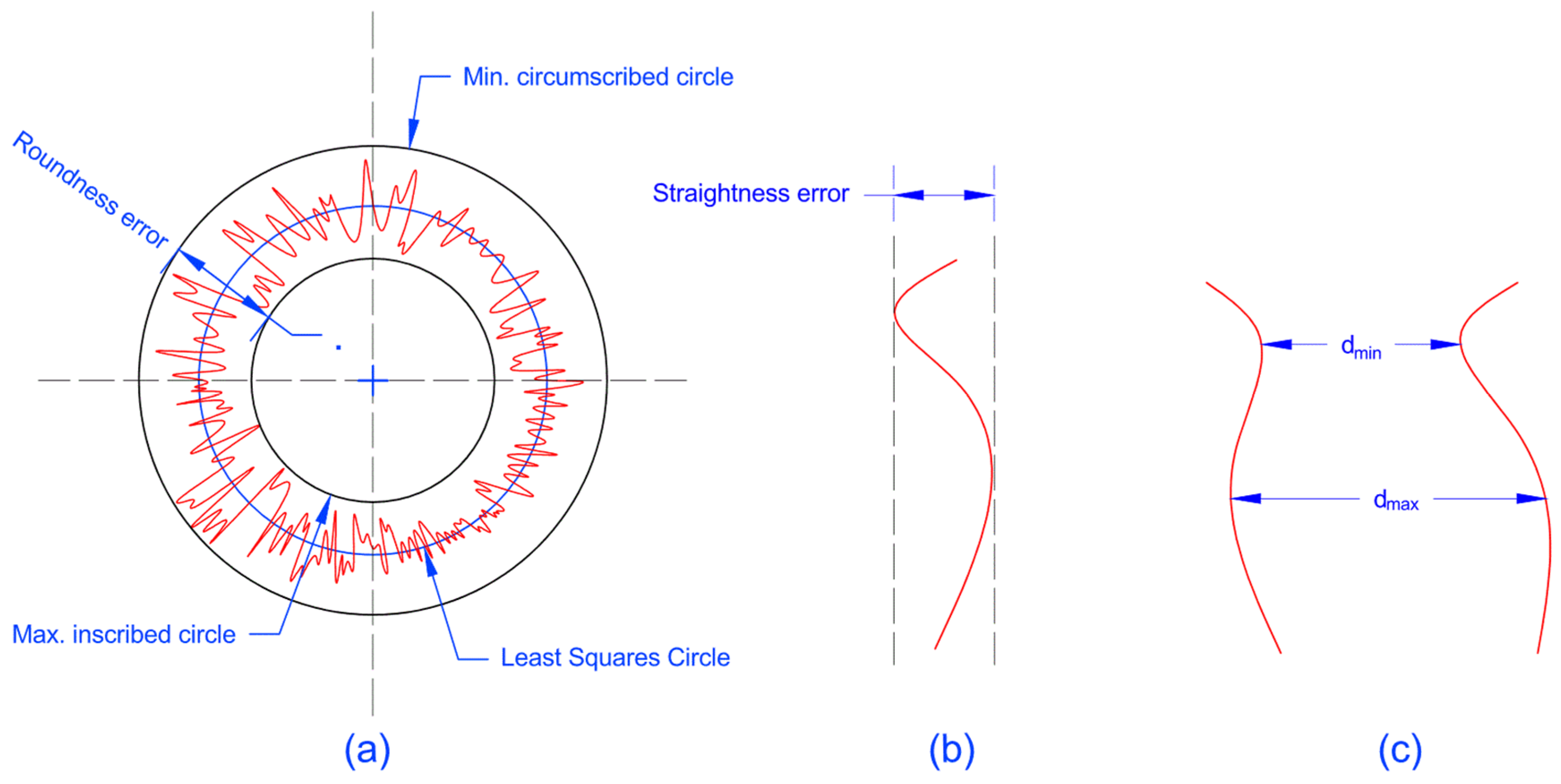
To check if the use of the conical liner affected the roundness of the liner’s cross sections, the roundness errors were calculated at different elevations. The roundness was evaluated with the least squares circle method [
14]. Briefly, the roundness error is the difference between the maximum and minimum circles that confine all the data points in the cross section (see
Figure 6a). Furthermore, the straightness error is calculated as the minimum distance between two straight lines that contain all the points as explained in
Figure 6b. The straightness error represents the change of the radius over the length, while the roundness error represents the change of the radius over the circumference. The parallelism error equals the difference between maximum and minimum distances between points at identical elevations in two lines facing each other, as explained in
Figure 6c and Equation (5).
The maximum value of the parallelism error is the summation of the straightness error of these two lines. The parallelism represents the change of the diameter over length, and thus shows the change in the bore tightness in a certain direction. This error is critical for both engine friction and PRCL performance. The reason for the use of both straightness and parallelism error is to predict the closeness of the liner’s wall to the required straight parallel shape, since the parallelism error alone cannot predict the existence of parallel curved walls. The results are summarized in
Table 2,
Table 3 and
Table 4.
Table 2 and
Table 3 show that both the parallelism and straightness of the liner increased in the fired state when a conical liner was used. The parallelism deviation decreased by a factor of three from values of around 12 µm to values around 4 µm. Simultaneously, the straightness error decreased from values of around 6 µm to values around 3 µm, which indicates that the walls of the liner became straighter and more parallel. They also showed almost the same values for both elliptical and circular cross sections, which indicates that the parallelism and straightness were independent of the liner cross section. In the thrust–antithrust direction, the liner was almost straight and parallel. An identical deviation of two micrometers out of a straight line was found at the top region of the liner on both sides. Here, the reason was given essentially from the pre-tightening load [
25]. It can be assumed that this deviation could also be reduced if the longitudinal bore shape of the liner in its cold state was processed with a detailed nonlinear shape. Then, this shape could be derived from the reverse deviation of the fired state deformation. For the front–rear direction, a deviation from a straight shape occurred in the lower part in the rear side due to an uneven supply for the combustion heat from the terminal side and from the side of the adjacent cylinders. This led to a certain eccentricity in the lower part of the liner.
From
Table 4, it can be seen that the roundness error increased significantly in the fired state if a circular shape was used in the cold state. This holds true for both the straight and the conical circular liner. If the cold state has an elliptical shape in the assumed parameters of the ellipse (see
Figure 3), the roundness error is reduced in the fired state significantly from values between 60 µm and 70 µm to values between 10 µm and 15 µm. This holds true for both the initially straight and the initially conically shaped liners. The roundness error is mainly related to blow-by and oil leakage to the combustion chamber. A larger roundness error implies that the piston rings need an increased pretension to prevent the leakage. This increases the frictional losses to a certain extend. This contribution is, however, rather small.
The parallelism error influences the friction losses more directly. On the one hand, the deviation from the straight parallel shape of the liner leads to varying oil film thickness between the piston ring and skirt and the cylinder liner. This can increase the friction. In the extreme case of the bore diameter being locally smaller than the piston diameter, the friction would increase drastically. On the other hand, the clearance between piston ring/skirt and cylinder liner can also increase, which can lead to increased secondary movement of the piston, which affects the friction. This implies that the parallelism error can possibly have more influence on the friction than the roundness error, even if it has smaller values. Although the roundness error is slightly smaller for the initially straight elliptical liner, the influence on the parallelism must be regarded. In sum, both influences are therefore regarded best with the initially conically and elliptically shaped liners.
These results agree with and explain the results found in the literature. For example, the study done by Edtmayer et al. [
15] showed that using a larger bore diameter in the bottom of the liner decreases the friction. This can be referred to the fact that this type of honing increases the straightness and parallelism of the deformed liner in the hot state.
6. Conclusions
The uneven distribution of combustion heat within an internal combustion engine leads to a significant increase of the diameter at the upper part of the liner compared to that at the lower part. This leads to increased friction and oil losses. This study assumed that an originally conical liner in its cold state could be used to reach a nearly cylindrical form in its fired operation state. This would improve the PRCL conformation and thus reduce the friction and the oil losses. To study that, a numerical validated gasoline engine model was used. With a numerical FEM simulation model, the deformation behavior of the liner was investigated between the cold state and a typical operation point of the engine at 4000 rpm.
The simulation case was based on a four-cylinder NISSAN CA18 gasoline engine, and experimental data of the roundness influence was given as a validation case. The study was done for the terminal cylinder located at the end of the engine with regard to the asymmetric thermal load from the neighbor cylinder on one side. From the first simulations of the deformation of the initially cylindrical liner for experimentally given temperature profiles, the resulting deformation was determined as a function of height. The larger temperatures in the upper section of the liner led to increased deformation. In the given case, the radius was increased by 30 µm.
In order to reach a nearly cylindrical liner shape, an initially conical liner was designed where the inclination angle was derived from the inverse of the calculated difference of the deformation between the upper and the lower section of the liner. Based on an earlier study [
14], the cross section of the liner was also regarded and was varied to be either circular in the cold state or to be slightly elliptical in such a way that the uneven thermal load led to a circular cross section in the fired state. In this study, both effects were regarded in a combined way. Using the validated FEM model, the detailed liner deformation was simulated for the thermal and stress conditions which were relevant for a full load operation point of the engine at 4000 rpm.
The numerical simulation results showed that the use of the conical liner in the cold state enhanced the parallelism in the fired state by a factor of three in such a way that the parallelism error reduced from about 12 µm to values in the range of 4 µm. Moreover, the straightness in the fired state enhanced by a factor of two in such a way that the straightness deviation error reduced from about 6 µm to values in the range of 3 µm. This indicates that the liner’s walls became more parallel and straighter. The remaining straightness error occurred at the upper part of the liner and was the result of the pre-tightening load. The utilization of a conical elliptical liner also reduced the roundness error in the fired state significantly from roundness error values of 60 µm to 70 µm to values in the range of 10 µm to 15 µm. The combination of both effects in conically and elliptically shaped liners has a great potential for increasing roundness, parallelism, and straightness in the fired engine state. This can possibly lead to reduced friction. Moreover, the oil losses can be reduced. With that, it might be possible to reduce the contact pressure of the piston rings, which, by itself, would additionally reduce the friction loss of the engine.
The approach and methodology described in this article provide a good starting point to analyze one of the most complex and critical areas in internal combustion engines. It has to be seen, if such complex shaped liners, i.e., the combination of a conically and elliptically shaped liners, will lead to advantages in real engines. For that, detailed measurements of the crank-angle resolved friction forces are planned in the near future on the single cylinder diesel test engine at the Leibniz University of Hannover [
29,
30,
31].


