1. Introduction
With the recent diversity of IT devices and the growth of multimedia services, Internet traffic has increased explosively, causing traffic pattern changes and the surging of network loads, which result in the decline of service quality. This is due to the technological limits under which the current rigid and closed Internet network architecture operates. This architecture is complex to manage, and it is difficult to create a new service as the current Internet cannot flexibly cope with expanding network capacity. In order to tackle this problem, networks should be open with virtual software computation and the Software Defined Network (SDN) is a technology achieving these aims [
1,
2].
The SDN decouples data and control layers, unlike the traditional Internet architecture where data and control layers exist together. In SDNs, a controller in the control layer carries out basic functions for a centralized network control such as forwarding control, management of topology and resource states and routing control based on a global view on the network state. It flexibly operates networks through software by determining differentiated forwarding and packet processing rules for upper-layer application services and sending them to lower-layer SDN switches. The SDN switches do not need to implement or operate the existing complex protocol. They are simple because they only have to perform instructions from the SDN controller at the control layer [
3,
4].
In the SDN, packets are handled in a flow unit. The flow entries are generated by controller and managed in the flow table of the switch based on the packets-related information, such as packet source, destination and processing methods. If the switch receives the packets, it uses the packet information to search the matching flow entries with the corresponding packets from the flow table and takes corresponding actions, such as forwarding, modification and removal of packets. When a corresponding flow entry does not exist, the switch generates a flow entry that contains new information by communicating with the controller. This flow table is managed within the limited memory capacity of the switch. The flow table consists of Ternary Content Addressable Memory (TCAM) which is expensive and high power-consuming. The number of flows can be more than 8 million in typical enterprise networks so that the flow table cannot contain all of flow entries at the same time [
5,
6,
7]. Moreover, it is hard to configure a network with switches of the same memory capacity when the network scale becomes large and, thus, different switches of many vendors are used to configure one. In this case, switches with relatively low performance can bring about frequent flow entry replacements in the packet forwarding process. It can cause more packet forwarding delay and controller load increase, which can decline the performance of the entire network and degraded user’s Quality of Service (QoS) [
8,
9,
10]. Hence, reducing the number of the flow entry replacement and controller overhead is very important in the SDN.
The main contributions of our paper are summarized as follows.
We describe what happens when the flow table is overflowed. We explain the operation of the switch and the controller, and show how they communicate with each other through the OpenFlow protocol messages.
We propose a new flow entry replacement scheme to reduce the chance of overflowing the flow table. The proposed Short Flow First (SFF) scheme identifies the flow characteristics using matching periods of each flow entry and manages the flow entries based on the characteristics. It decreases the processing and message exchanging overheads.
We implement the SFF and the typical flow entry replacement schemes such as First-In-First-Out (FIFO), Least Frequently Used (LFU) and Least Recently Used (LRU), on the switch code. The proposed scheme does not require the change of the switch architecture. It just needs to modify the code of data structure of the flow table at the switch. The code is compatible with the real SDN switch and also runs in the Mininet environment.
Lastly, we compared the performance of the proposed scheme with the typical flow replacement schemes.
In this paper,
Section 2 presents existing studies to reduce the controller overhead.
Section 3 explains the problems of overflowing the flow table in different SDN switches.
Section 4 delineates the SFF scheme, which is the flow entry replacement scheme that takes into account the flow characteristics.
Section 5 describes the experimental results for performance evaluation on the SFF scheme as well as the other schemes. Lastly,
Section 6 reaches a conclusion and suggests a plan for future works.
2. Related Works
In the SDN, network overhead can increase in some processes like packet processing and controller switch management. Many studies are carried out to decrease the overhead. A.R. Curtis et al. [
11] is a framework that uses a flow-based monitoring technique. A switch processes newly arrived packets by employing a wildcard technique without sending PacketIn Message to the controller. When the packets arriving at the switch match the flow, the number of flow count increases. When the count reaches a preset threshold, the flow is classified as Elephant flow and sent to the controller to request flow processing. This processing decreases the number of PacketIn Message sent from the switch to the controller. However, the technique using the wildcard may lead to abuse of limited switch memory. A. Dixit et al. [
12] balanced the overhead of the controller by relocating a switch managed by a controller with high overhead to a different controller. However, it is impossible to accurately and precisely distribute a load of controllers as it is relocated in the switch unit. The load may also occur because an additional setup process is required to change the controller responsible for the switch. S. Hassas Yeganeh et al. [
13] proposed the Kandoo framework to reduce the controller overhead caused by frequent network events. The framework divided the control plane controllers into a root controller and local controllers. For distributing the controller overhead, the root controller processed a request related with an overall network state and multiple local controllers processes the rest of the events. A. Tootoonchian et al. [
14] proposed a distributed platform that consisted of a logically centralized controller and physically multiple distributed controllers. They proposed a NOX controller [
15] application where each controller manages the networks locally. However, these methods are hard to be implemented since handover exists among multiple controllers and the standard of east-west bound Application Programming Interface (API), an interface among the controllers, is not defined. S. Banerjee et al. [
16] proposed a tag-in-tag scheme that routes multiple flows through certain paths to reduce the flow entry. Similarly, K. Agarwal et al. [
17] proposed a forwarding method that decouples the network core from the edge and uses virtual and physical Media Access Control (MAC) addresses for each to reduce the use of flow table. However, these methods are also hard to apply as Address Resolution Protocol (ARP) spoofing requires change of the host kernel. N. Ha et al. [
18] proposed an architecture to efficiently manage the flow table. It saves the memory of the flow table and searches the flow-entry fast. However, it did not discuss issues when the flow table is full. ONOS [
19] mentioned the flow table overflow due to the limitation of flow table size. It proposed a way to differentiate flows and adaptively choose routing paths for reducing flow entries. However, it did not suggest a way to solve the problem after the flow table is overflowed.
E. Kim et al. [
20] proposed a flow table management mechanism with LRU algorithm. It caches expired flow entries as inactive entries rather than deleting them. The inactive entries are replaced with new flow entries if necessary. Therefore, the proposed mechanism is for handling the expired flow entries and it does not suggest a new flow entry replacement algorithm. Instead, it uses the LRU algorithm. Z. Li et al. [
21], T. Kim et al. [
22] and H. Zhu et al. [
23] proposed timeout-based mechanisms for flow table management. They dynamically adjust the idle timeout of each flow entry according to corresponding flow patterns. The timeout mechanism is the representative mechanism of the proactive approach. It deletes flow entries, even though the flow table is not full, to prevent from the processing and message overheads caused by flow entry replacement. However, they cause the unnecessary overhead processing and message overheads before the flow table is not full. Moreover, the flow table can be full even though they proactively delete the flow entries because of inaccurate prediction for optimizing idle timeouts. As a result, they also need a flow entry replacement algorithm and should be combined with it.
3. Flow Table Overflow with Different Switches
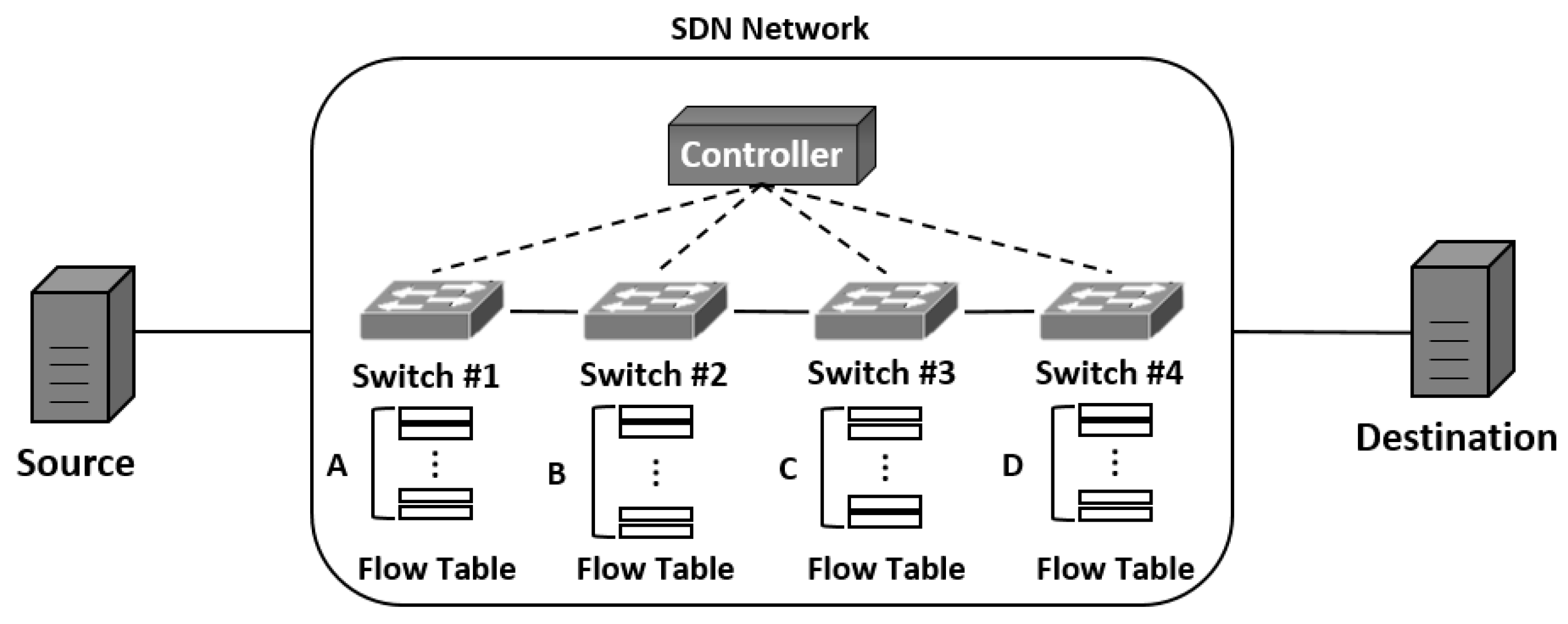
Figure 1 shows a simple linear network using SDN that has switches with flow tables of different sizes. If the flow entry for the packet does not exist in the flow table of the switch when the packet is forwarded from a source to a destination, a new entry is generated by exchanging messages with the controller and inserted to the table. If multiple packets that have different flow entries are forwarded after some time, the flow table is filled with the generated entries. If the packet having a new flow entry is sent when the flow table is full, the flow table experiences table overflow. When this happens, the existing entries should be deleted from the flow table to generate and insert the new flow entries. The deletion and insertion is performed through multiple exchanges of messages between the switch and controller. If 100 packets with different flow entries are forwarded under the network environment, as shown in
Figure 1, for example, 100 flow entries are generated and the switch whose flow table size is smaller than 100 experiences the flow table overflow. This leads to a flow entry replacement in the flow table.
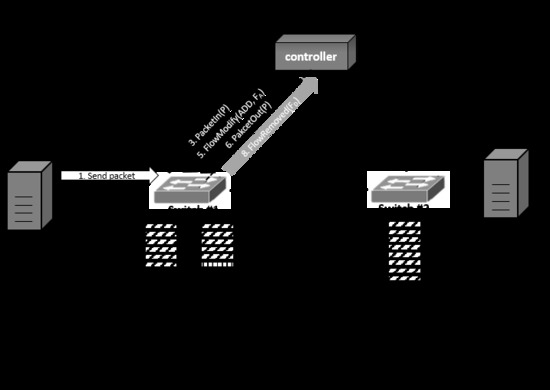
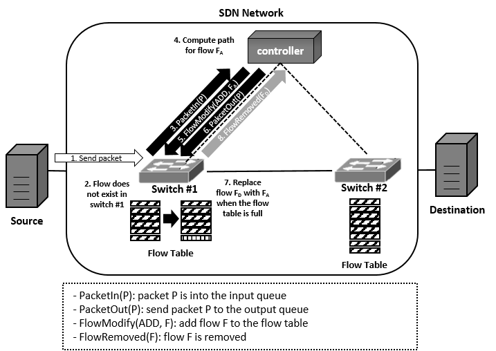
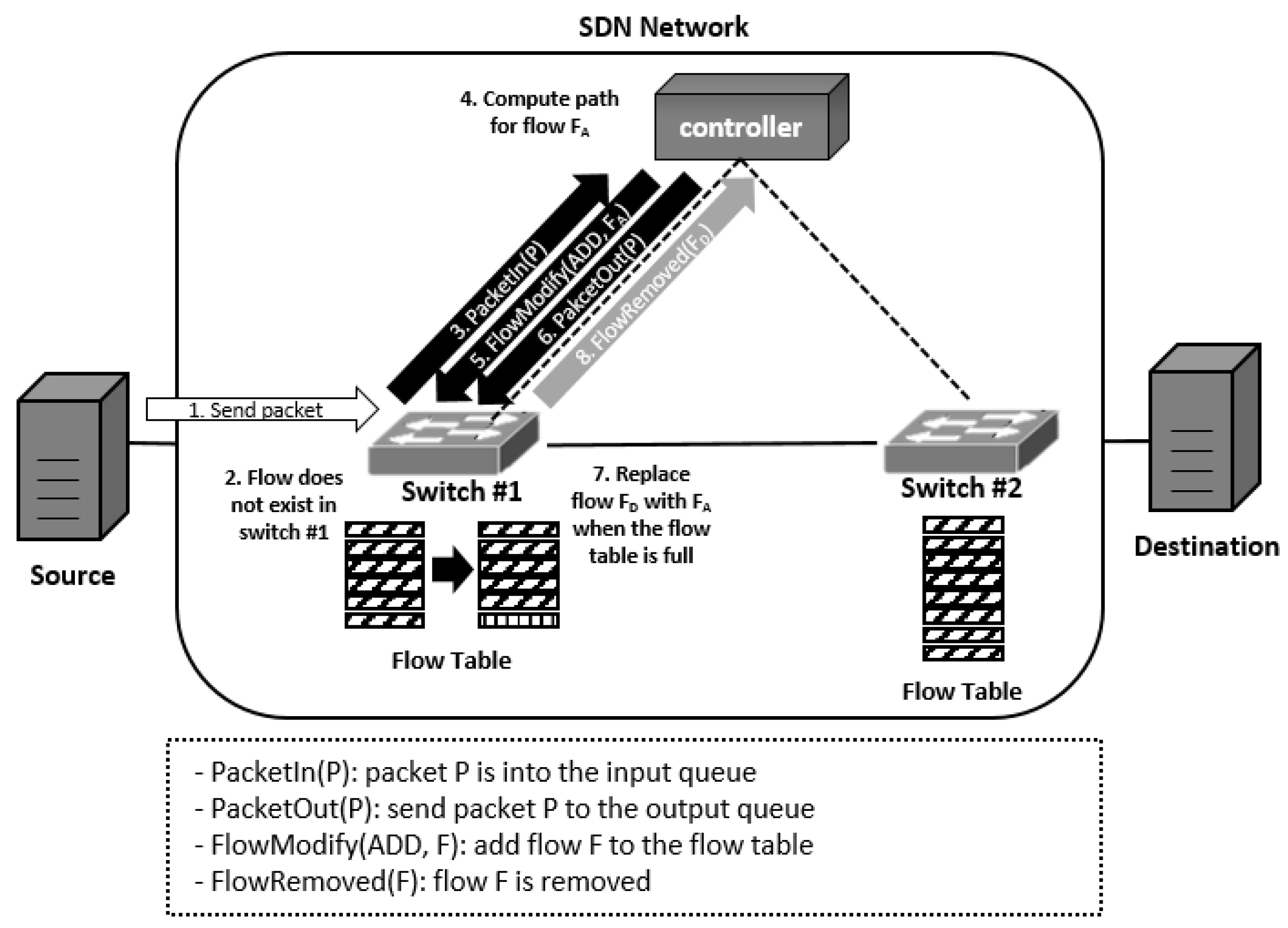
Figure 2 shows the process of deleting the existing flow entries and generating new ones when the flow table overflow occurs. If a switch receives a new packet when the flow table is full, the switch looks up a matching flow entry with the packet from the table. If there is no flow entry, the switch sends PacketIn message to the controller to generate it. The controller computes paths and sends FlowModify message to the switch to insert the flow entry to the table. PacketOut message is also sent to designate the destination of the packet. However, when the flow table is full, the existing flow entry should be deleted to insert the new flow entry. In order to do so, the switch selects a flow that seems not to be used any longer and replaces it with the new one. Then, it transmits the FlowRemoved message to the controller to notify the changed status of the flow table. Overall, the controller and switch exchange the messages four times in the process so as to update the flow table. The frequent flow entry replacement causes the overhead to the controller and switch so that the replacement should be minimized to reduce the network overhead in the SDN.
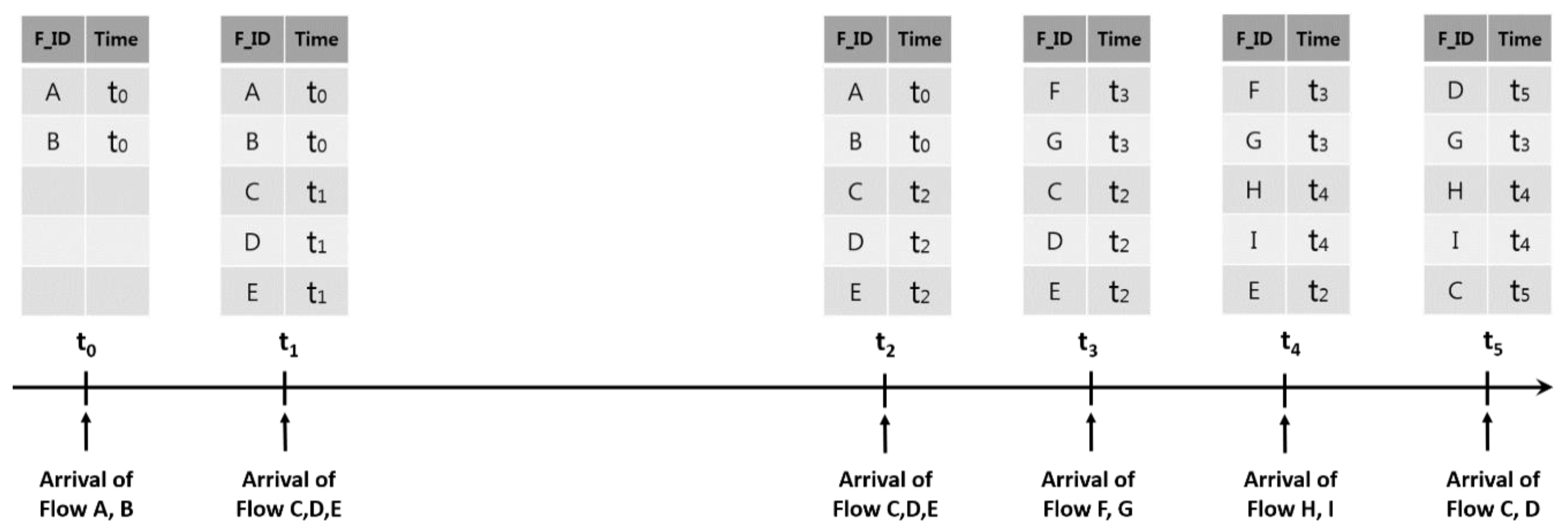
Figure 3 is an example of inefficient flow entry replacements when applying the LRU scheme to decide the flow entry to delete. In the figure,
F_ID represents the identifier to distinguish the flow entry and Time representing matching time of the flow entry. Let us assume that Flow
C and
D are the ones related with the multimedia services and are generated repeatedly unlike the web traffic. In the figure, Flow
A and
B are inserted at
t0. Then Flow
C,
D and
E arrive at
t1 and entries corresponding to the flows are generated at the flow table. When Flow
C,
D and
E arrive again at
t2, they match the existing entries. When Flow
F and
G arrive at
t3, Flow
A and
B are deleted and Flow
F and
G are inserted according to the LRU scheme. After Flow
H and
I arrive at
t4, Flow
C and
D are deleted from the current flow table by the LRU scheme. Finally, Flow
E and
F are deleted and Flow
C and
D are inserted when Flow
C and
D arrive again at
t5.This example shows that Flow
C and
D are deleted from the flow table by generation of other flows although they are related with the multimedia services that are repeatedly used. Consequently, the overhead of the switch and controller increased by exchange messages to generate the flow again and the user QoS falls. Therefore, the traffic flow that is repeatedly sent like the multimedia traffic should be long maintained in the flow table to avoid unnecessary overhead of SDN and ensure the user QoS. In order to do this, we proposed a new flow entry replacement scheme that prevents an inefficient flow entry replacement by considering flow characteristics such as multimedia and web.
4. Proposed Scheme
In this section, we introduce a new flow entry replacement method considering the traffic characteristics, called the SFF scheme. Controversial flow replacement schemes such as FIFO, LRU and LFU do not consider traffic pattern when replacing flow entries. On the contrary, the SFF scheme takes into account the traffic characteristics. It classifies the flow into short flow and long flow with matching periods of the flow entry. The short flow is a flow entry generated by packets that occur temporarily for intermittent services like the web. In general, it matches only for a short time and does not match after a certain period of time. Therefore, the short flow can be deleted quickly after it is not used for some time. On the other hand, the long flow has recurring packets and matches repeatedly with a period. Multimedia services are one example of the long flow and it should stay in the flow table until the services end to prevent overhead from happening such as deleting or regenerating the flow entry. The proposed SFF scheme reflects the flow characteristics to manage the table. In the SFF scheme, the ones with the short flow are chosen as the candidates for replacement prior to others when a flow entry needs to be replaced due to flow table overflow. The entries of the long flow are excluded from the first replacement candidates and given the opportunity to stay longer in the flow table.
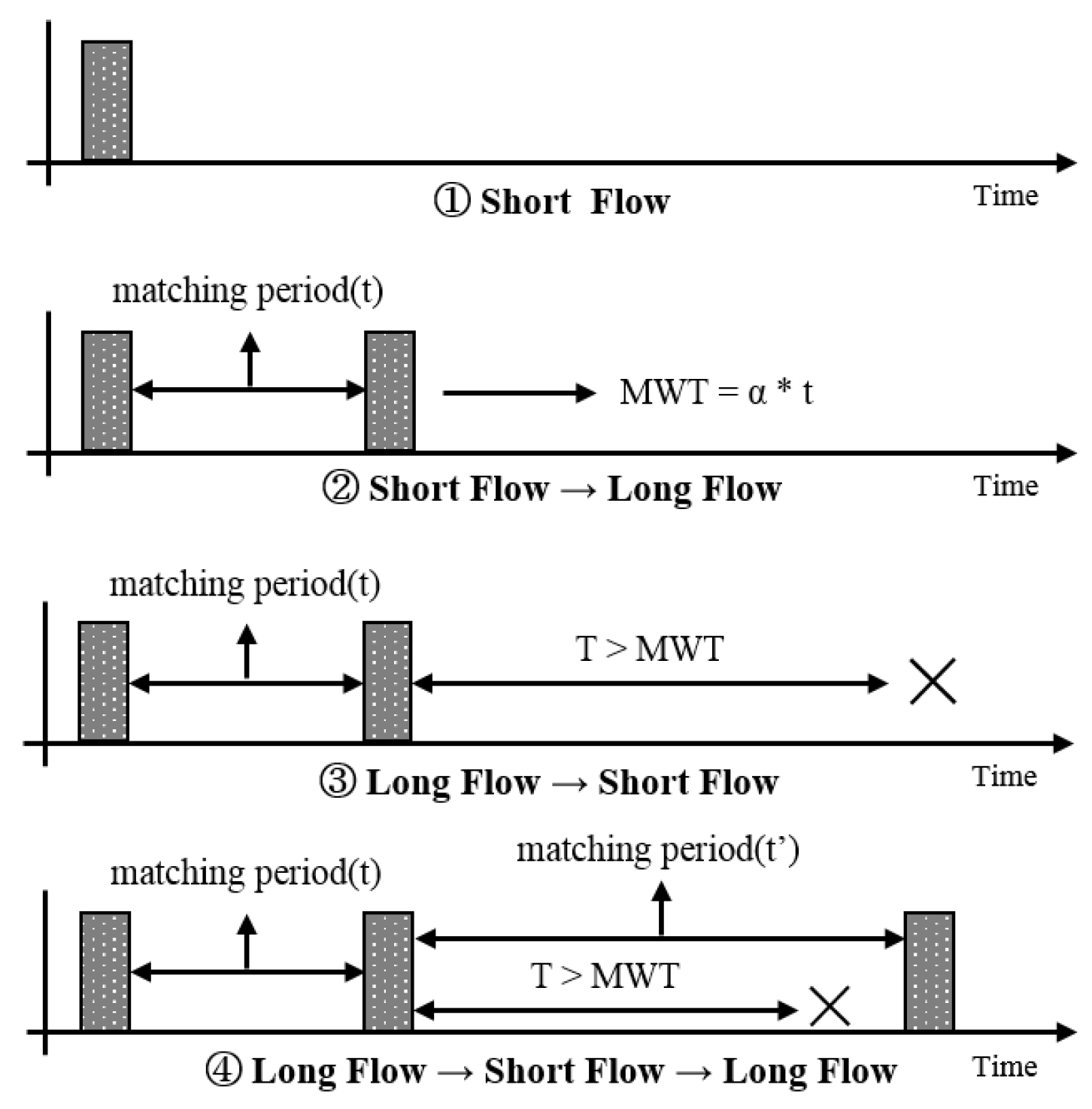
The SFF scheme uses a matching period of the flow entry to figure out the flow characteristics.
Figure 4 shows the process of identifying the flow characteristics based on the flow matching period. In the figure, the matching period represents the inter-arrival time of two successive packets that the same flow has.
T represent the time difference between the current and the last packet arrived. In the SFF scheme, when the initial packet arrives to generate a new flow entry, the characteristics of that flow are assigned as the short flow. If the short flow entry matches with the second arriving packet before being deleted from the flow table, this entry changes into the long flow. The time between the first and second packets becomes the matching period,
t, of that flow and Maximum Waiting Time (MWT) of that flow is established as
α∙
t where
α is the weighting factor. The entry that changed into the long flow is kept as the long flow if the interval between the arrival times of the two packets is smaller than the MWT. The long entry flow should be stayed a bit more in the flow table even though the packet corresponding to the long flow entry does not arrive after the MWT passes since the long flow entry has the possibility of receiving the packet again. When a packet belonging to the long flow entry does not arrive within the MWT, the entry is changed into the short flow. If the entry that changed into the short flow matches a packet again before being deleted from the flow table, a new matching period will be generated with the inter-arrival time of packets and the entry is changed into the long flow again. The characteristics of the flow entries are figured out in this manner and each of them has a different matching period and different MWTs. If the flow table overflow occurs, the flow entry replacement scheme is applied only to the entries identified as short flow among those in the flow table. If there is no short flow, the flow entry replacement scheme selects and deletes an entry among the long flow entries.
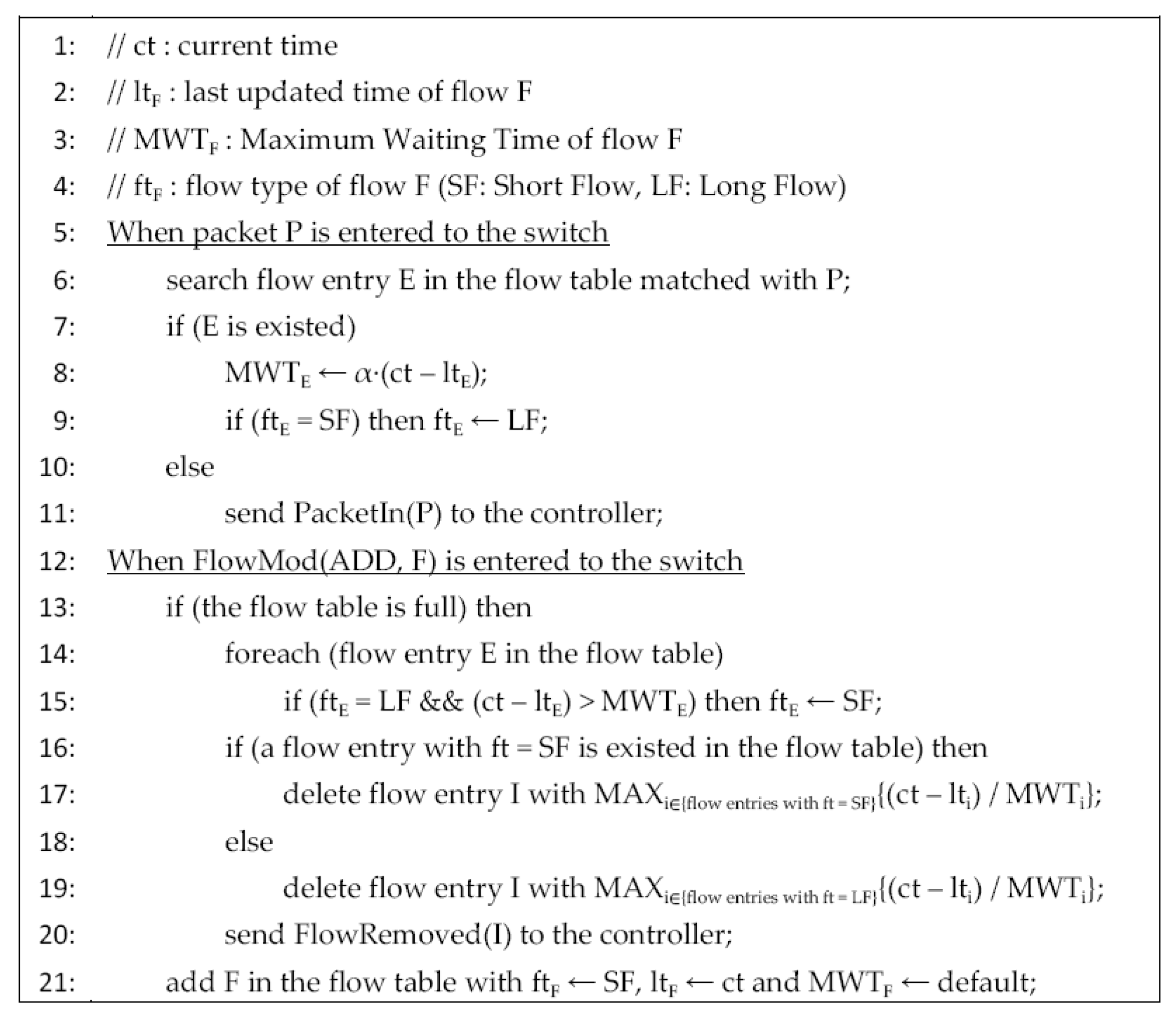
Figure 5 is the pseudo code of the SFF scheme. When a packet is entered to the switch, it searches the flow entry matching with the packet in the flow table (line 6). If the matched flow entry is existed, the switch sets the MWT of the entry as the product of
α and matching period between the last updated and the current times (line 8). After that, the switch sets the type of the entry as the long flow (line 9). If there is no matched flow entry, the switch sends the PacketIn message to the SDN controller (line 11). When the controller gets PacketIn message from the switch, it computes paths and sends FlowModify message to the switch to insert the flow entry to the flow table. When the switch gets the FlowMod message of adding a flow, it starts the process to insert the flow into the table (line 13–21). If the flow table is full, the switch updates the flow types (line 14–15), then selects and deletes a target flow entry to be replaced with it (line 16–19). First, the switch attempts to select and delete the target entry that has the maximum value of the matching period dividing by the MVT among short flows (line 16–17). If there is no short flow entry, it selects and deletes an entry among long flows (line 18–19). After deleting the target entry, the switch sends the FlowRemoved message to the controller (line 20). Lastly, the switch adds the newly inserted flow in the flow table (line 21).
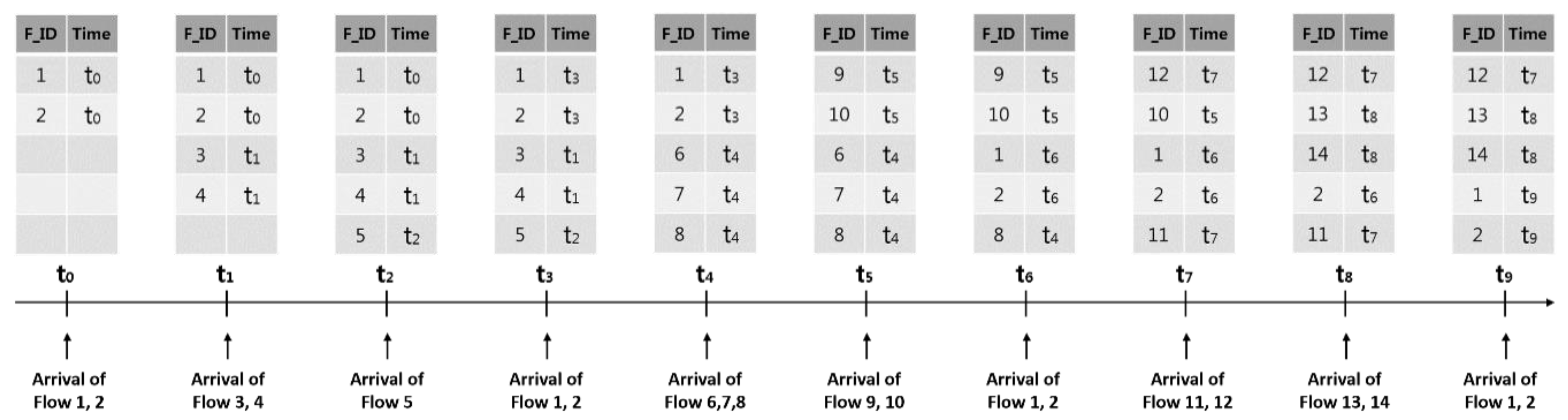
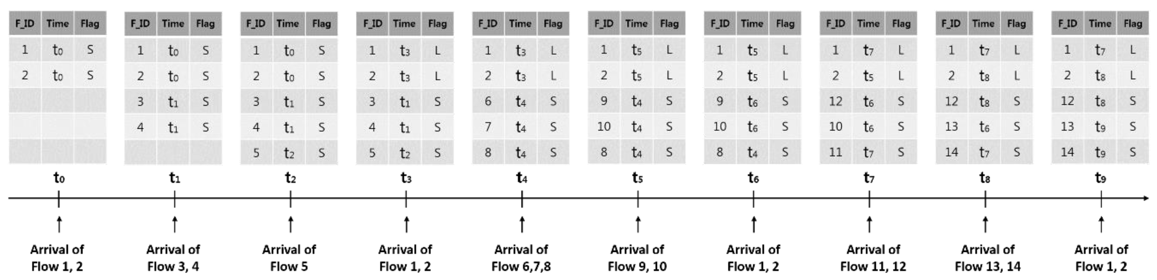
Figure 6 demonstrates an example of updating the flow table when the LRU scheme is applied. In the figure, the flow table is full after Flow 1 and 2 initially reach the switch followed by Flow 3, 4 and 5 in sequence. Flow 1 and 2 that arrive at
t3 match the existing entries. As there is no space left in the flow table for Flow 6, 7 and 8 arriving at
t4, Flow 3, 4 and 5 are deleted and Flow 6, 7 and 8 are inserted by the LRU scheme. When Flow 9 and 10 reach
t5, Flow 1 and 2 are deleted by the LRU scheme from the flow table though they are to be matched again because they are the long flows. Instead, Flow 9 and 10 are inserted. Once Flow 1 and 2 arrive at
t6, the existing Flow 6 and 7 are deleted and Flow 1 and 2 are inserted. Flow 1 is deleted by Flow 14 at
t8 and regenerated at
t9. As suggested, Flow 1 and 2 are repeatedly matching flow entries. However, the process of deletion and regeneration by other flows was found to be inefficient.
Figure 7 shows an example of updating the flow table using the SFF scheme. In the figure, the flags, S and L represent the short and long flow types, respectively. The flags of Flow 1 and 2 are assigned as S after they arrive. The flags are also assigned as S when Flow 3, 4 and 5 reach
t2. Flow 1 and 2 are identified as repeatedly matching flows with a period when they arrive at
t3, changing the flags into L. The period of these flows is
t3-
t0. When Flow 6, 7 and 8 reach
t4 with the flow table full, the flows to be deleted are determined among the short flows whose flags are assigned as S. Thus, Flow 3, 4 and 5 of the short flows are deleted and Flow 6, 7 and 8 are inserted. Flow 6 and 7 are deleted and Flow 9 and 10 are inserted at
t5 as well. Flow 1 and 2 arriving at
t6 match the existing flow entries. The flow entries assigned as S at
t7 and
t8 are deleted and new flows are inserted. Lastly, Flow 1 and 2 match the existing flow entries again upon reaching
t9. The LRU scheme in this example replaced the flow entries 13 times while the SFF scheme replacing them 9 times. This indicates that unnecessary insertion and deletion may decrease when the flow entry replacement considers the flow characteristics.
5. Evaluation
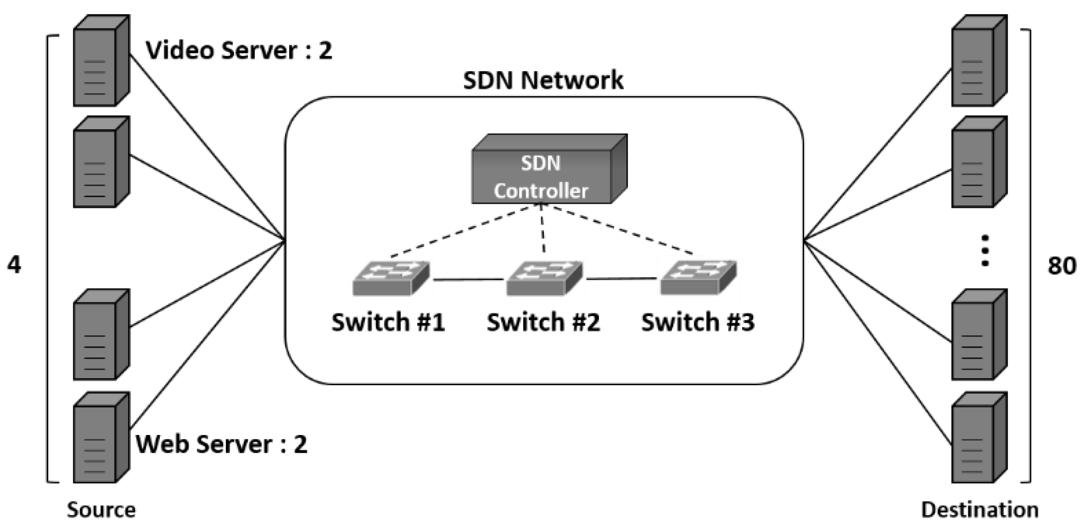
This section explains the performance evaluation of the flow entry replacement schemes. We set up the SDN environment with 4 servers and 80 destinations like
Figure 8 by employing Mininet emulator [
24]. The source served as video servers and web servers while the destination served as clients. We used the ONOS controller [
19] as the SDN controller. The number of flows was 320. The numbers of the video and web flows were 160 and 160, respectively. The sizes of flow table of switches were varied with 96, 128 and 160 entries. We also evaluated the performance of the FIFO, LFU and LRU schemes to compare with the performance of the SFF scheme.
There are two types of flow: web and video. The web flow generated 50 packets and waited for 10 s. The video flow periodically generated a packet per 200 milliseconds. We generated packets for 300 s using the Ostinato packet generator [
25]. Source IP and MAC addresses, destination IP and MAC addresses of the packet were used as matching field to see if the packet received by the switch matches the flow entry in the flow table. The flag information to check the flow characteristics as well as the period information to check the matching period of the flow entry was used. Each data set was forwarded via a packet replay tool known as tcpreplay [
26]. The optimal value of the weighting parameter α may vary depending on the network and traffic conditions. In the proposed scheme, the long flow is determined based on the inter-arrival times of packets of the flow. However, the inter-arrival times between packets in a long flow vary because of the packet jitter. So, we need a smoothing factor α to flexibly wait for the next packet of the long flow. The weighting parameter α determines the margin time to wait for the next packet. If it is small, the only regular flows, of which packets are arrived very periodically, are maintained as the long flows and get a priority to stay long at the flow table. However, we cannot allow the network jitter occurring in some long flows. If α is big, a long flow can wait longer than the expected time for the next packet. But, the flow irregularly generating packets can be also maintained as the long flow. Therefore, we need to set the weighting parameter α appropriately. If not, the proposed method chooses the improper flow entries for the flow replacement so that its performance goes down due to high flow entry miss rate. The significance of appropriate α is depending on the actual traffic pattern in the deployed network. Before fixing the target network, we cannot exactly determine how much the performance is degraded when the inappropriate α is used. However, in our experimental network deployment, the inappropriate α has shown about 19% performance degradation at the worst case. We found that the best value of the weighting parameter is 5.0 in our experimental environment.
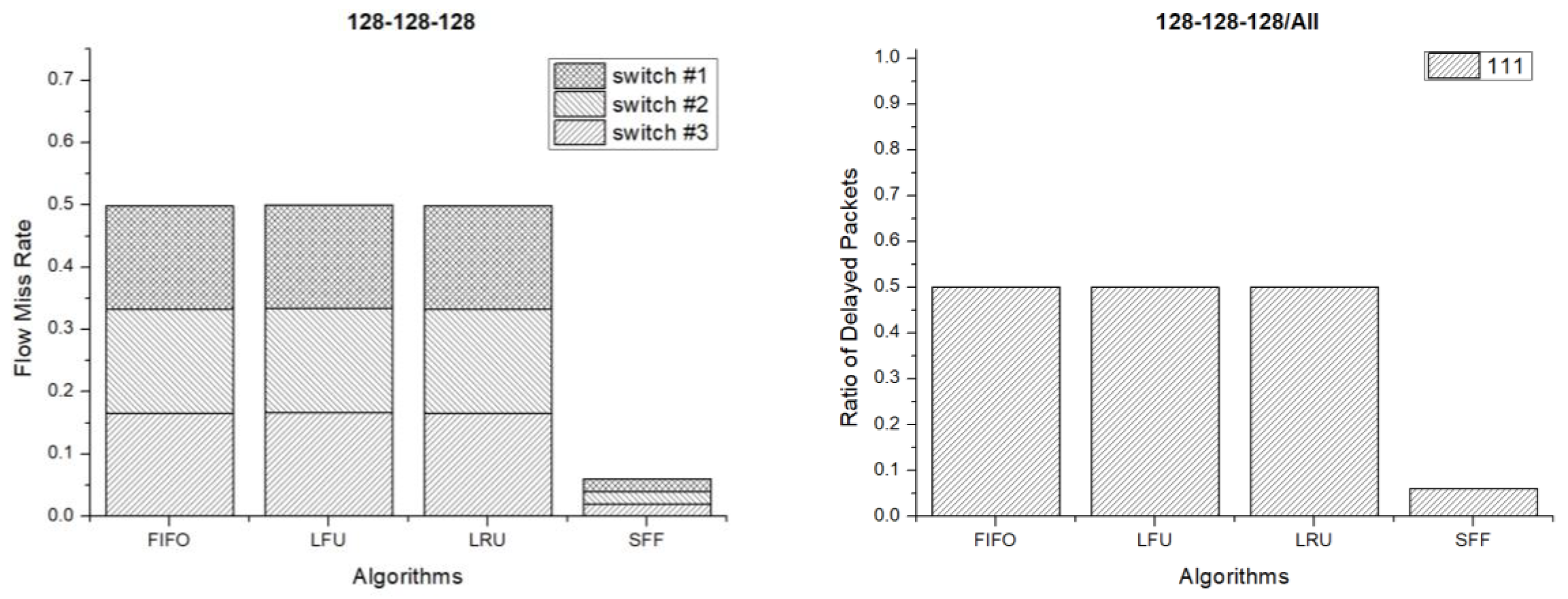
Figure 9 shows the flow miss rate and ratio of delayed packets when the flow table size of each switch is 128 entries. The flow miss rate is the ratio of the number of incoming packet not to find a matched flow entry over the number of total packets. If the flow miss rate is high, the flow entry replacement occurs frequently. The message exchange overhead between the controller and switches using the OpenFlow protocol increase so that the SDN controller overhead increase when the flow miss rate is high. The ratio of delayed packets is the number of packets experiencing delay due to flow miss over the total number of the delivered packets. A delayed packet arrives late at the destination and may not be used in proper time due to jitter. The network jitter may degrade the quality of service and can be large when the ratio of delayed packets is high. So, we have to reduce the ratio of delayed packets as much as possible. The amount of delay which packets experience due to flow entry miss deeply depends on the target network environment. It goes up if the controller is far from the switches, the network is congested, or the speeds of the devices are slow. Moreover, it can be dynamically changed when these conditions are dynamically changed. Therefore, we have shown the ratio of the number of the delayed packets, instead of the delayed time which delayed packets are experienced. As seen in the result, the flow miss rate of the SFF scheme is very low in comparison with the other schemes such as FIFO, LFU and LRU. Therefore, the message exchange and SDN controller overheads of the SFF scheme are lower than those of the other schemes. The ratio of delayed packets means the ratio of the number of the delayed packets over the number of the total packets. In the result, the legend 111 means that a packet is delayed due to flow mismatching at switch #1, #2 and #3. The legend 100 means that a packet is delayed at switch #1 only. As seen in the result, almost half of the packets experienced the delay at all switches in the FIFO, LFU and LRU scheme. However, only 7% of the packets experienced the delay in the SFF scheme. Therefore, less packets experienced delay when the SFF scheme is used.
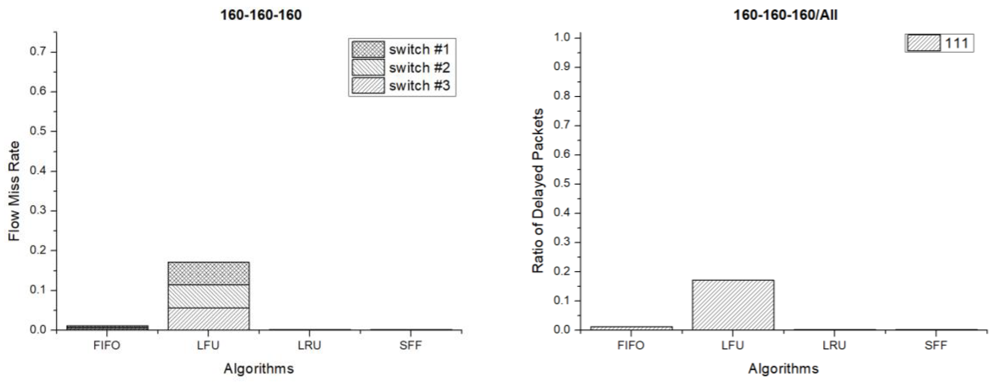
Figure 10 shows the flow miss rate and ratio of delayed packets when the flow table size of each switch is 160 entries. In the results, the flow miss rate and ratio of delayed packets are lower than those of 128 flow entries. Less flows are missed and less packets are delayed because of the large size of the flow table. In this case, the LFU scheme has the worst performance. However, the LRU and SFF schemes have good performances.
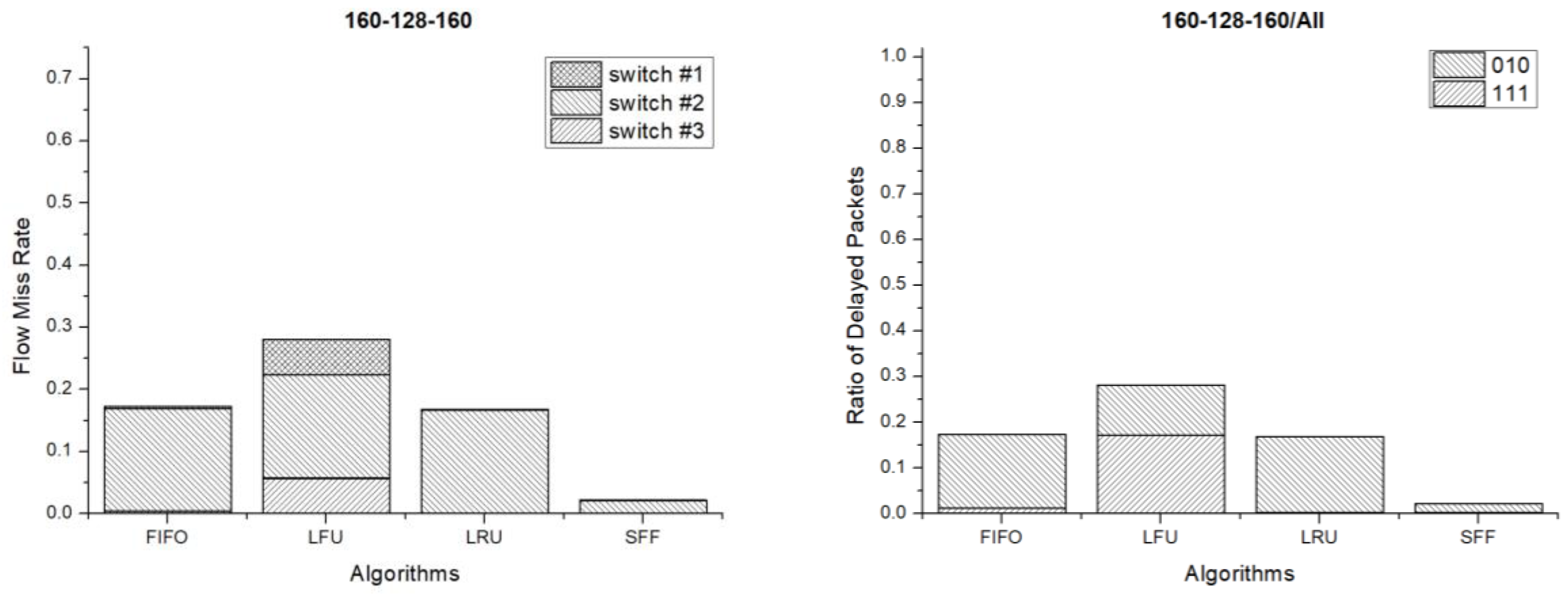
Figure 11 shows the results when the flow table sizes of each switch are 160, 128 and 160 entries respectively. The flows are missed and packets are delayed the most at switch #2 because the switch has the smallest number of flow entries. In this case, the LFU scheme has the worst performance and the SFF has the best performance.
Figure 12 shows the results when the flow table sizes of each switch are 160, 128 and 96 entries respectively. In this case, the flows are missed and packets are delayed the most at switch #3 because it has the smallest flow table size. In the results, the SFF scheme has the lowest flow miss rate and the number of delayed packets is also the smallest in comparison to the other schemes. As a result, the SFF scheme shows the best performance.
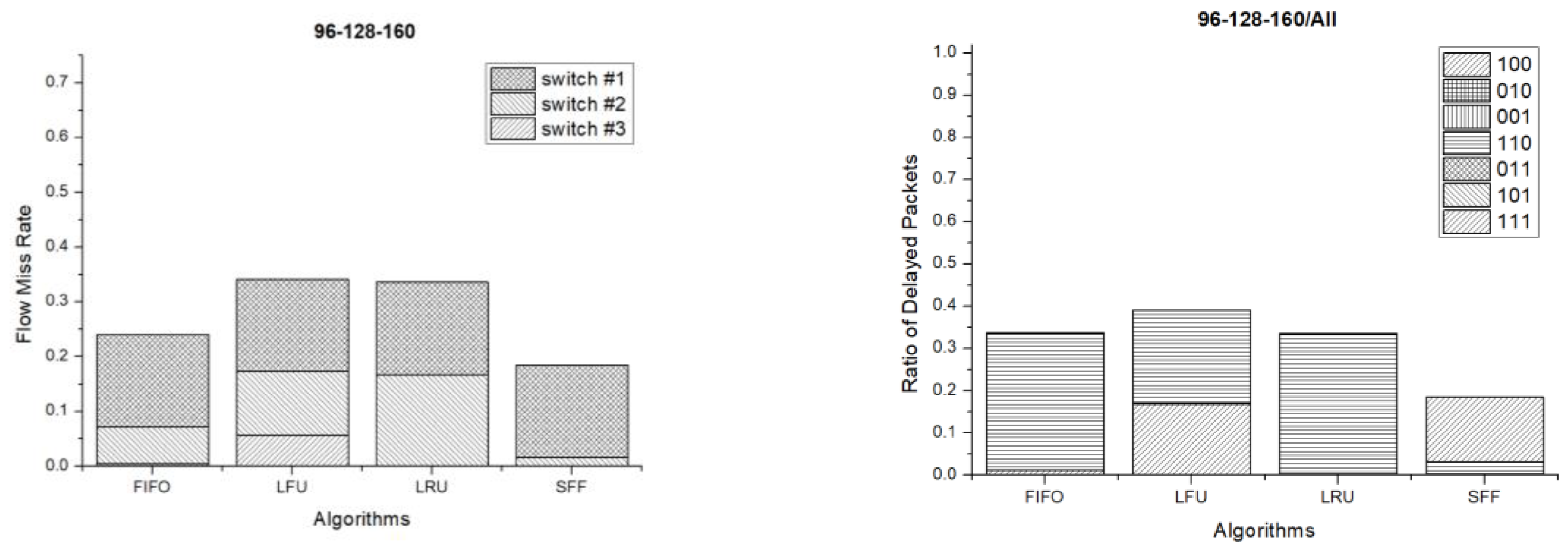
Figure 13 shows the flow miss rate and ratio of delayed packets when the flow table sizes of each switch are 96, 128 and 160 entries respectively. In this case, the flows are missed and the packets are delayed the most at switch #1 on the contrary of the previous case. This is also because the switch has the smallest flow entries. Even in this case, the SFF scheme has the lowest flow miss rate and the number of delayed packets is the smallest too. Therefore, the SFF scheme shows the best performance even in this case.
6. Conclusions
This study explains the issues that can arise when SDN is configured with switches of very different sizes of the flow tables and proposes the SFF scheme to resolve them. The SFF scheme classifies the flow into short and long flows by using matching periods of the flow. It replaces the short flow first and keeps the long flow as long as possible. The long flow may send packets for a longer time than the short flow so that it reduces the total number of changing flow entries. Therefore, the SFF scheme also reduce the overheads of the switch and message exchange. According to our experiments with diverse switch conditions, the proposed SFF scheme shows the best performance in comparison with the other FIFO, LFU and LRU schemes.
The proposed scheme divides the flows into the short flows and long flows. Then, it attempts to delete the entry among short flows first. To do this, the proposed scheme searches the flow table twice in the worst case. In addition, it requires a change of the logic of the switch that may be a little more difficult than that of the controller. However, the change of the controller will cause an increase of the processing overhead of the controller and the message exchange overhead using OpenFlow protocol between the switch and the controller.
It is believed that many studies should be conducted to reduce the packet processing time and improve the switch memory efficiency in the future. Moreover, studies have to be carried out focusing on a technique that allows choosing an efficient scheme that fits a situation with more diverse traffic patterns, as well as real Internet traffic. Additionally, the studies and performance comparisons need to be performed under the actual networks such as datacenter, enterprise and contents delivery networks. Lastly, studies have to be combined and optimized with diverse hardware aspects such as TCAM, Application-Specific Integrated Circuit (ASIC), millions of flow entries capacity and gigabits per second port speed. This is because the final performance of a system is the performance of the final system implemented. In this paper, we showed the performance of flow entry replacement algorithms at the algorithmic level. Our algorithm showed a good performance with diverse aspects. However, it is not the final performance. It can be combined with TCAM at the implementation level and we need to consider the latency of the TCAM which occurs when we access, insert and delete a flow entry in the TCAM in the future. In addition, we have to make a mathematical model to support the proposition that the innovation can be scaled up to real and high performance physical switches.


