Towards Model Synchronization for Consistency Management of Mechatronic Systems


Abstract
:1. Introduction
2. State-of-the-Art
2.1. Integration Approach
2.2. Model Federative Approach
2.3. Model Transformation Approach
2.3.1. The Use of Profiles or SysML Extensions
2.3.2. The Emergence of Model Transformation Languages
2.4. Inconsistency Management Approach
3. Methodology
3.1. Model Transformation Process
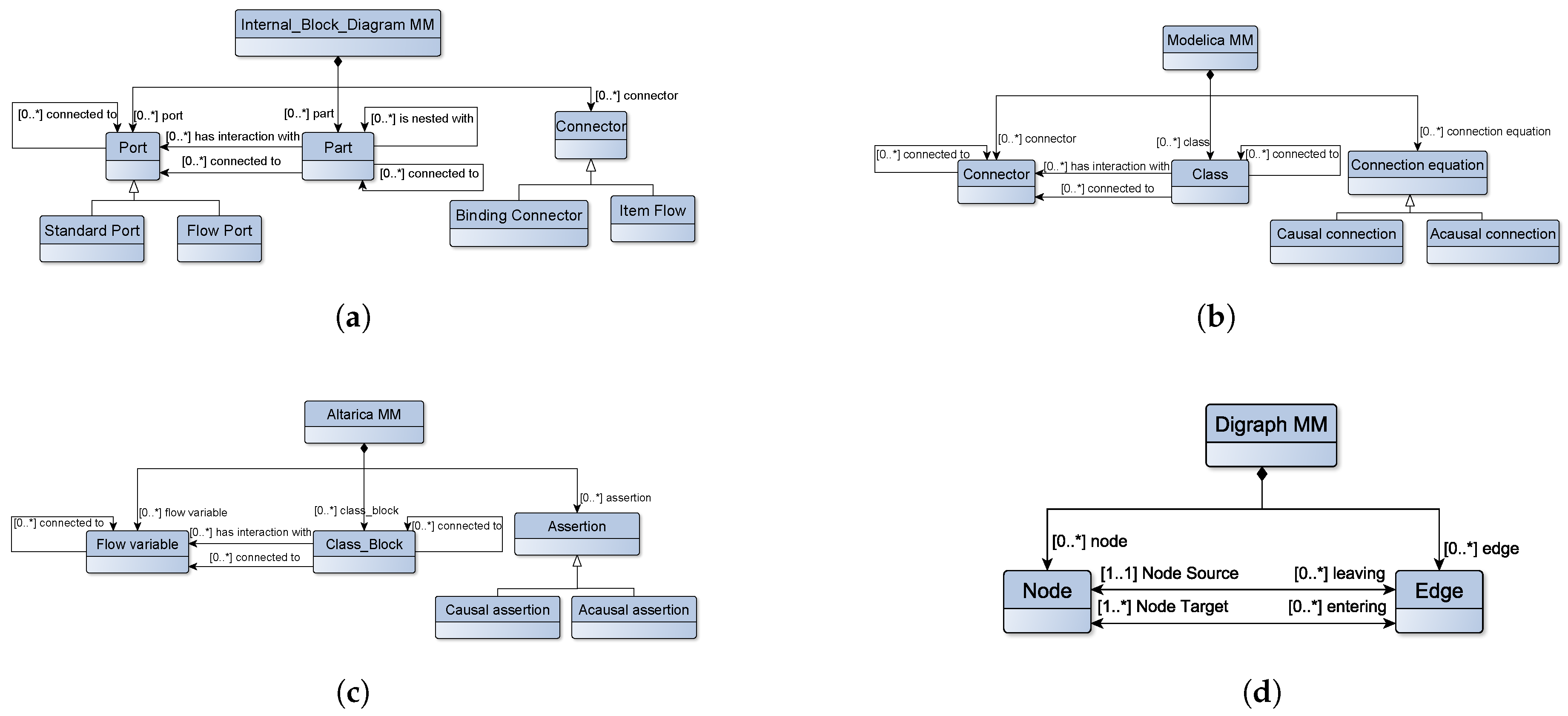
3.1.1. Metamodeling
- SysML Internal Block Diagram (IBD) metamodel
- Modelica metamodel
- Altarica metamodel
- Digraph metamodel
3.1.2. Expressing Model Transformation Rules
- Abstraction rules
- Concretization rules
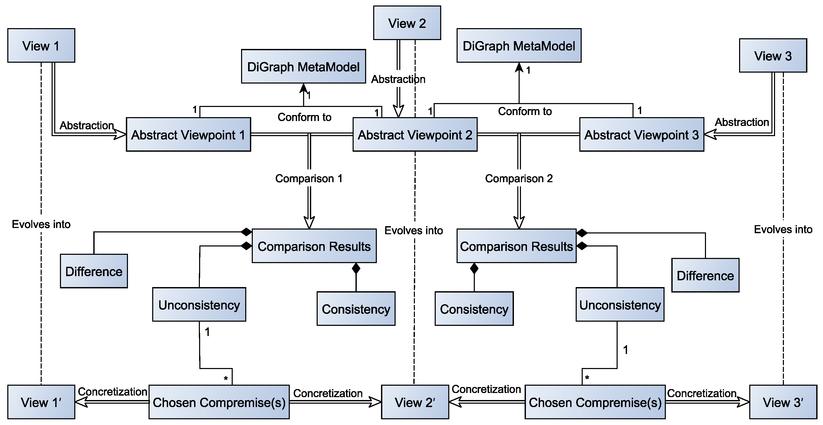
3.2. Comparison Process
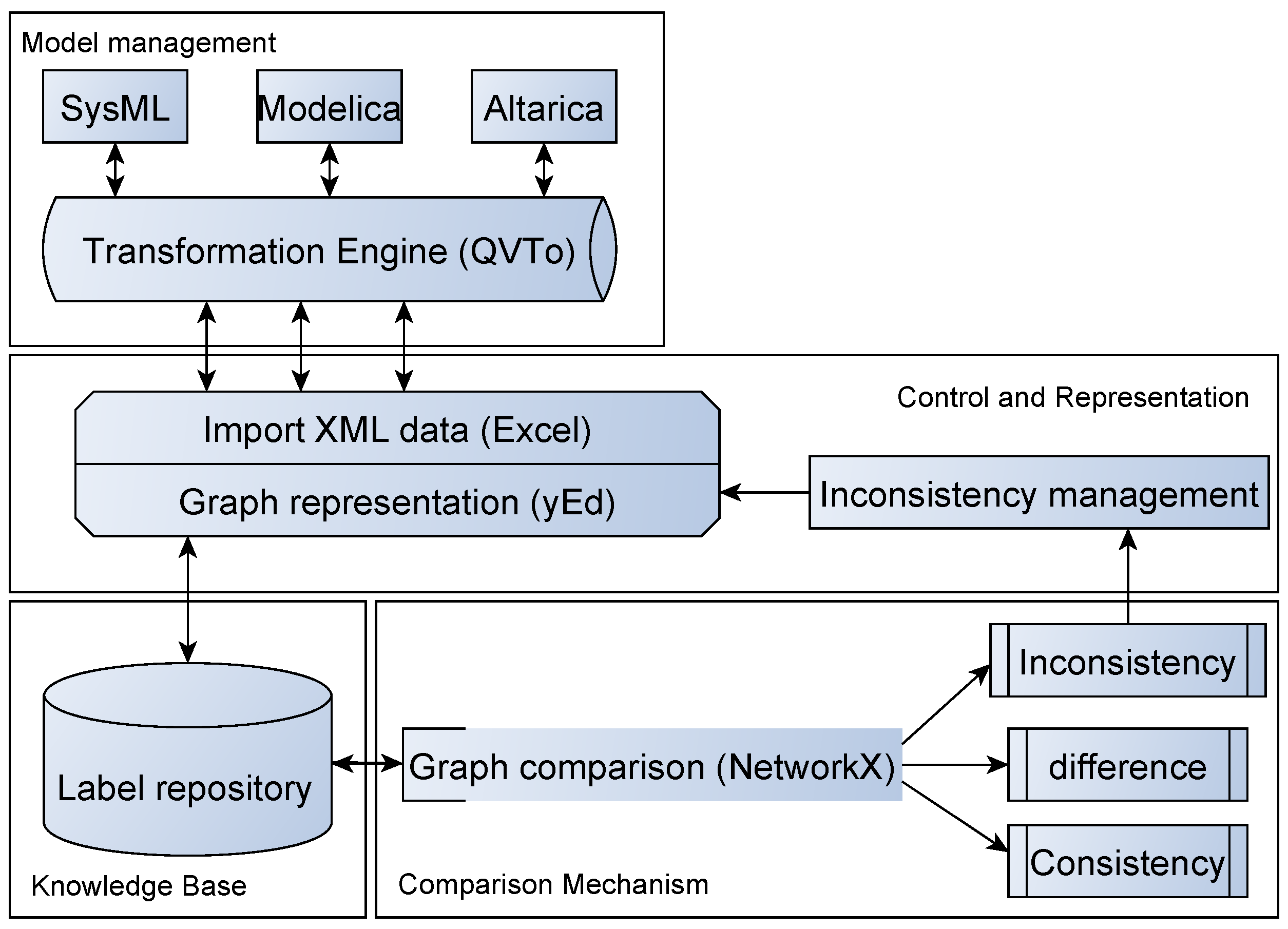
4. Proof of Concept Implementation
4.1. Model Management
- Direct transformation
- Indirect transformation
4.2. Comparison Mechanism
4.3. Control and Representation
5. Case Study
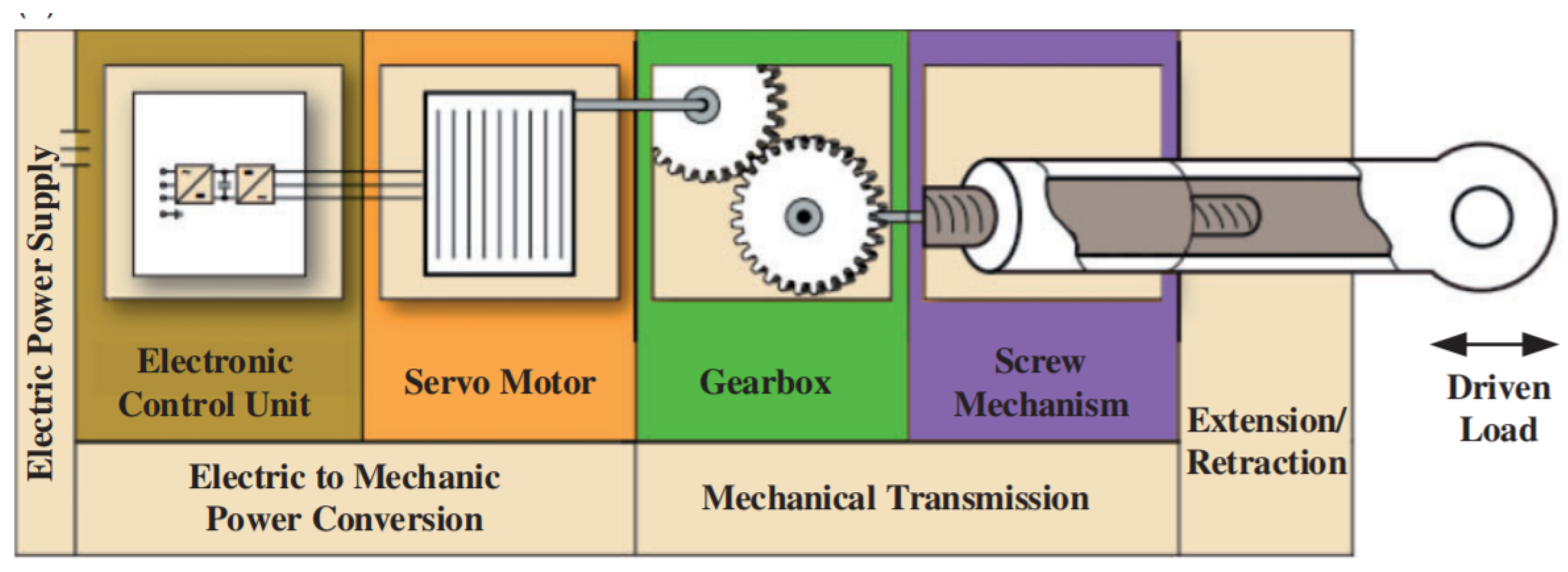
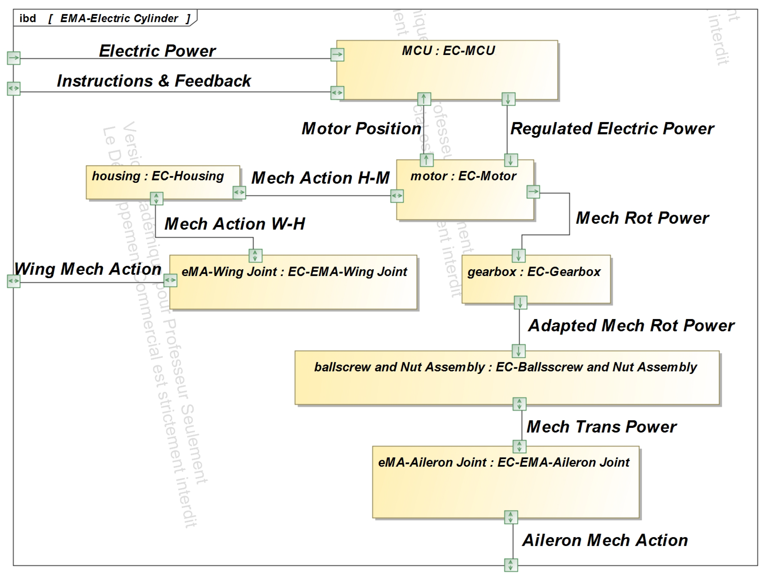
5.1. Design Models of the EMA
5.1.1. System Engineering Perspective (SysML)
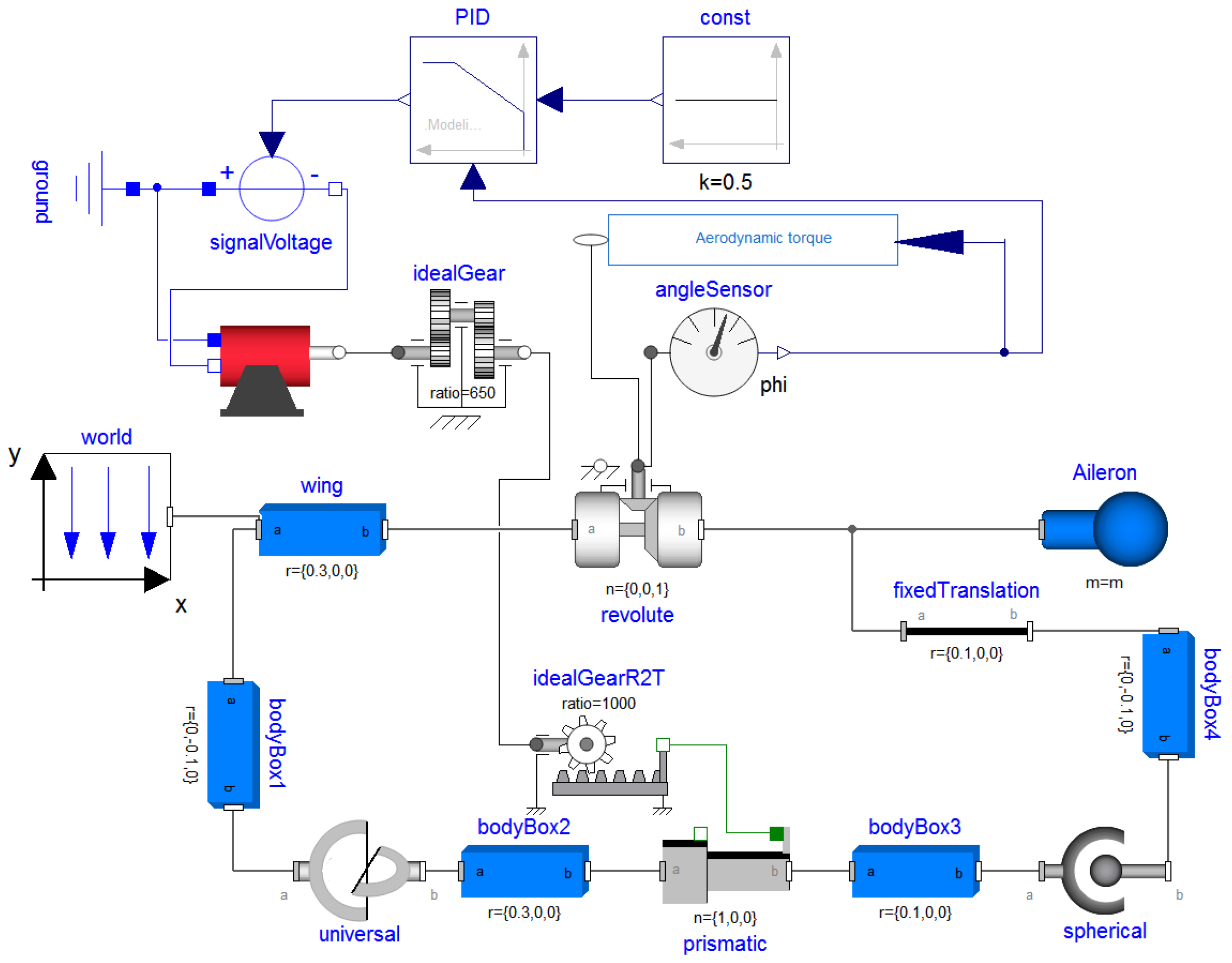
5.1.2. System Behavior Analysis (Modelica)
5.1.3. Dysfunctional Behavior Analysis (Altarica)
| class NRComponent … end | ||||
| block EMASystem | ||||
| block Instructions | … | end | ||
| block ElectricPower | … | end | ||
| block IncidenceSensor | … | end | ||
| block MCU | … | end | ||
| block EMAWingJoint | … | end | ||
| block Housing | … | end | ||
| block EMAAileronJoint | … | end | ||
| block Motor | … | end | ||
| block Gearbox | … | end | ||
| block BallScrewNutAssembly | … | end | ||
| block Observer | … | end | ||
| end | ||||
| assertion | end | |||
| MCU.vfFromElectricPower := ElectricPower.vfToMCU; | ||||
| MCU.vfFromInstructions := Instructions.vfToMCU; | ||||
| MCU.vfFromIncidenceSensor := IncidenceSensor.vfToMCU; | ||||
| Motor.vfFromMCU := MCU.vfToMotor; | ||||
| Gearbox.vfFromMotor := Motor.vfToGearbox; | ||||
| BallScrewNutAssembly.vfFromGearbox := Gearbox.vfToBallScrewNutAssembly; | ||||
| Observer.vfFromBallScrewNutAssembly := BallScrewNutAssembly.vfToEMAAileronJoint; | ||||
| Observer.vfFromHousing := Housing.vfOut; | ||||
| Observer.vfFromEMAWingJoint := EMAWingJoint.vfOut; | ||||
| Observer.vfFromEMAAileronJoint := EMAAileronJoint.vfOut; | ||||
| end | ||||
5.2. Methodology Application
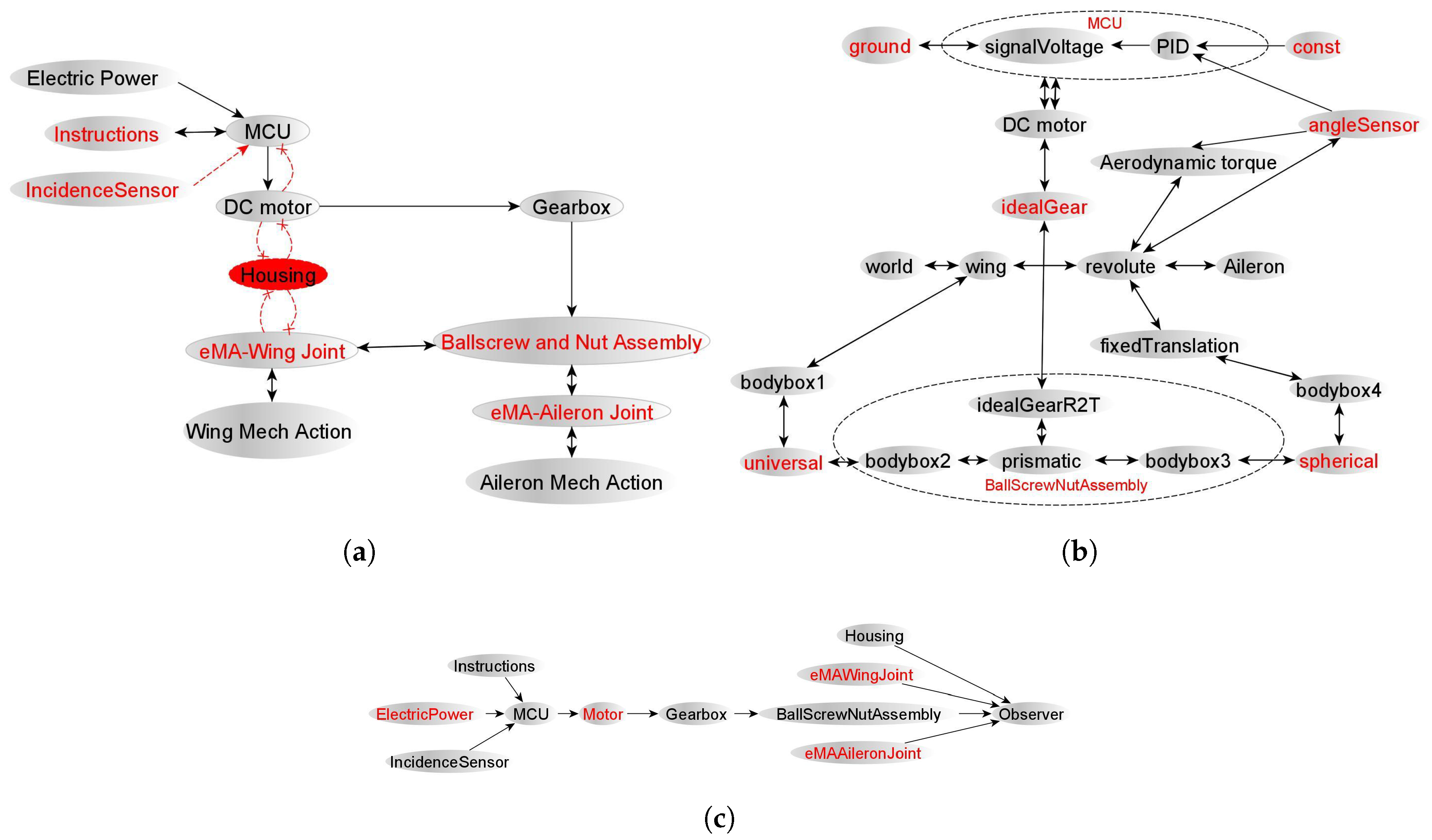
5.2.1. Abstraction
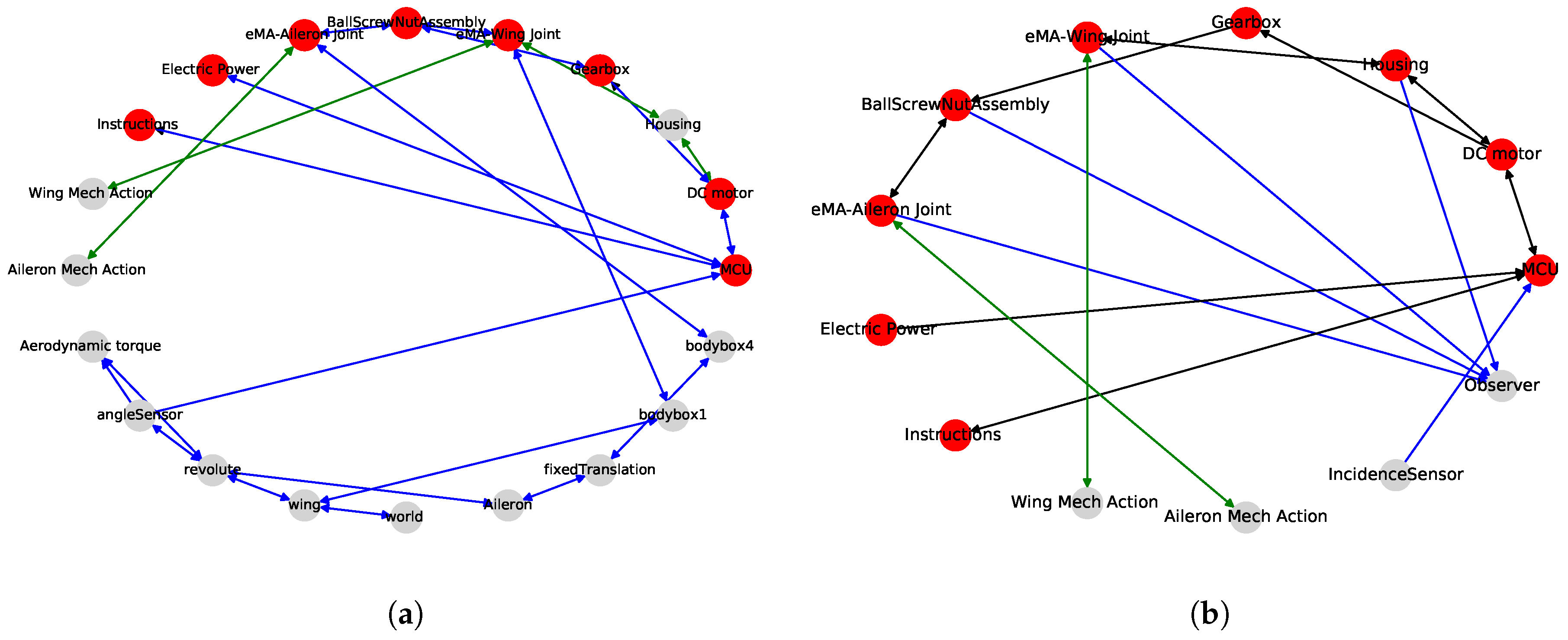
5.2.2. Comparison
- Unconventional naming
- Level of abstraction
- Design concerns
- Conflicting information
- Inconsistencies based on meta-level correspondences
- The omission of essential elements in system design
5.2.3. Concretization
6. Discussion
7. Conclusions
Author Contributions
Funding
Acknowledgments
Conflicts of Interest
References
- Isermann, R. Mechatronic systems: Concepts and applications. Trans. Inst. Meas. Control 2000, 22, 29–55. [Google Scholar] [CrossRef]
- Broy, M.; Feilkas, M.; Herrmannsdoerfer, M.; Merenda, S.; Ratiu, D. Seamless model-based development: From isolated tools to integrated model engineering environments. Proc. IEEE 2010, 98, 526–545. [Google Scholar] [CrossRef]
- Törngren, M.; Qamar, A.; Biehl, M.; Loiret, F.; El-Khoury, J. Integrating viewpoints in the development of mechatronic products. Mechatronics 2014, 24, 745–762. [Google Scholar] [CrossRef]
- Herzig, S.J.; Paredis, C.J. A conceptual basis for inconsistency management in model-based systems engineering. Procedia CIRP 2014, 21, 52–57. [Google Scholar] [CrossRef] [Green Version]
- Feldmann, S.; Herzig, S.J.; Kernschmidt, K.; Wolfenstetter, T.; Kammerl, D.; Qamar, A.; Lindemann, U.; Krcmar, H.; Paredis, C.J.; Vogel-Heuser, B. Towards effective management of inconsistencies in model-based engineering of automated production systems. IFAC-PapersOnLine 2015, 48, 916–923. [Google Scholar] [CrossRef]
- Spanoudakis, G.; Zisman, A. Inconsistency management in software engineering: Survey and open research issues. In Handbook of Software Engineering and Knowledge Engineering: Volume I: Fundamentals; World Scientific: River Edge, NJ, USA, 2001; pp. 329–380. [Google Scholar]
- Qamar, A.; Herzig, S.J.; Paredis, C.J. A Domain-Specific Language for Dependency Management in Model-Based Systems Engineering. MPM@ MoDELS 2013, 1112, 7–16. [Google Scholar]
- Hehenberger, P.; Egyed, A.; Zeman, K. Consistency checking of mechatronic design models. In Proceedings of the ASME 2010 International Design Engineering Technical Conferences and Computers and Information in Engineering Conference, Montreal, QC, Canada, 15–18 August 2010; pp. 1141–1148. [Google Scholar]
- Shah, A.A.; Kerzhner, A.A.; Schaefer, D.; Paredis, C.J. Multi-view modeling to support embedded systems engineering in SysML. In Graph Transformations and Model-Driven Engineering; Springer: Berlin/Heidelberg, Germany, 2010; pp. 580–601. [Google Scholar]
- Legendre, A.; Lanusse, A.; Rauzy, A. Toward model synchronization between safety analysis and system architecture design in industrial contexts. In Proceedings of the International Symposium on Model-Based Safety and Assessment (IMBSA 2017), Trento, Italy, 11–13 September 2017; Springer: Cham, Switzerland, 2017; pp. 35–49. [Google Scholar]
- Barendrecht, P.J. Modeling Transformations Using QVT Operational Mappings; Research Project Report; Department of Mechanical Engineering Systems Engineering Group, Eindhoven University of Technology: Eindhoven, The Netherlands, 2010. [Google Scholar]
- OMG. Meta Object Facility (MOF) Core Specification v 2.5.1. 2006. Available online: https://www.omg.org/spec/MOF/2.5.1/PDF (accessed on 9 August 2019).
- OMG. Model Driven Architecture (MDA). Available online: https://www.omg.org/mda/ (accessed on 26 February 2020).
- Mauborgne, P.; Deniaud, S.; Levrat, E.; Bonjour, E.; Micaëlli, J.P.; Loise, D. Preliminary Hazard Analysis Generation Integrated with Operational Architecture-Application to Automobile. In Complex Systems Design & Management; Springer: Cham, Switzerland, 2015; pp. 297–309. [Google Scholar]
- Kleiner, S.; Kramer, C. Model based design with systems engineering based on RFLP using V6. In Smart Product Engineering; Springer: Berlin/Heidelberg, Germany, 2013; pp. 93–102. [Google Scholar]
- Guychard, C.; Guerin, S.; Koudri, A.; Beugnard, A.; Dagnat, F. Conceptual interoperability through models federation. In Proceedings of the Semantic Information Federation Community Workshop, Miami, FL, USA, October 2013. HAL id: hal-00905036. [Google Scholar]
- Thramboulidis, K. The 3+1 SysML view-model in model integrated mechatronics. J. Soft. Eng. Appl. 2010, 3, 109. [Google Scholar] [CrossRef] [Green Version]
- Pop, A.; Akhvlediani, D.; Fritzson, P. Towards unified system modeling with the ModelicaML UML profile. In Proceedings of the 1st International Workshop on Equation-Based Object-Oriented Languages and Tools, Berlin, Germany, 30 July 2007; Conjunction with ECOOP; Linköping University Electronic Press: Linköping, Sweden, 2007; number 024. [Google Scholar]
- Paredis, C.J.; Bernard, Y.; Burkhart, R.M.; de Koning, H.P.; Friedenthal, S.; Fritzson, P.; Rouquette, N.F.; Schamai, W. An Overview of the SysML-Modelica Transformation Specification. In Proceedings of the INCOSE International Symposium, Chicago, IL, USA, 12–15 July 2010; Volume 20, pp. 709–722. [Google Scholar]
- Mhenni, F.; Nguyen, N.; Choley, J.Y. SafeSysE: A Safety Analysis Integration in Systems Engineering Approach. IEEE Syst. J. 2018, 12, 161–172. [Google Scholar] [CrossRef]
- Hildebrandt, S.; Lambers, L.; Giese, H.; Rieke, J.; Greenyer, J.; Schäfer, W.; Lauder, M.; Anjorin, A.; Schürr, A. A survey of triple graph grammar tools. Electron. Commun. EASST 2013, 57, 1–17. [Google Scholar]
- Adourian, C.; Vangheluwe, H. Consistency between geometric and dynamic views of a mechanical system. In Proceedings of the 2007 Summer Computer Simulation Conference, San Diego, CA, USA, 15–18 July 2007; Society for Computer Simulation International: San Diego, CA, USA, 2007; p. 31. [Google Scholar]
- Anwar, A.; Benelallam, A.; Nassar, M.; Coulette, B. A graphical specification of model composition with triple graph grammars. In Proceedings of the International Workshop on Model-Based Methodologies for Pervasive and Embedded Software, Essen, Germany, 4 September 2012; pp. 1–18. [Google Scholar]
- Finkelstein, A.; Gabbay, D.; Hunter, A.; Kramer, J.; Nuseibeh, B. Inconsistency handling in multi-perspective specifications. In Proceedings of the 4th European Software Engineering Conference, Garmisch-Partenkirchen, Germany, 13–17 September 1993; pp. 84–99. [Google Scholar]
- Gausemeier, J.; Schäfer, W.; Greenyer, J.; Kahl, S.; Pook, S.; Rieke, J. Management of cross-domain model consistency during the development of advanced mechatronic systems. In Proceedings of the 17th International Conference on Engineering Design (ICED 09), Palo Alto, CA, USA, 24–27 August 2009; Volume 6. Design Methods and Tools (part 2). [Google Scholar]
- Berriche, A.; Mhenni, F.; Mlika, A.; Choley, J.Y. Towards Model Synchronization in Model Driven Engineering of Mechatronic Systems. In Proceedings of the 2019 IEEE International Systems Engineering Symposium (ISSE), Edinburgh, UK, 3 October 2019; p. 8. [Google Scholar]
- OMG. Systems Modeling Language (OMG SysML), Version 1.4. 2012. Available online: https://www.omg.org/spec/SysML/1.4/PDF (accessed on 26 December 2018).
- Modelica Association. Modelica—A Unified Object-Oriented Language for Systems Modeling, Language Specification Version 3.4. 2017. Available online: https://www.modelica.org/documents/ModelicaSpec34.pdf/view (accessed on 24 April 2019).
- Batteux, M.; Prosvirnova, T.; Rauzy, A. System Structure Modeling Language (S2ML). 2015. Available online: https://hal.archives-ouvertes.fr/hal-01234903/document (accessed on 18 January 2019).
- Kotthoff, L.; McCreesh, C.; Solnon, C. Portfolios of subgraph isomorphism algorithms. In Proceedings of the International Conference on Learning and Intelligent Optimization, Ischia, Italy, 29 May–1 June 2016; pp. 107–122. [Google Scholar]
- Gallagher, B. The State of the Art in Graph-Based Pattern Matching; Technical report; Lawrence Livermore National Lab: Livermore, CA, USA, 2006. [Google Scholar]
- Ullmann, J.R. An algorithm for subgraph isomorphism. JACM 1976, 23, 31–42. [Google Scholar] [CrossRef] [Green Version]
- Cordella, L.P.; Foggia, P.; Sansone, C.; Vento, M. An improved algorithm for matching large graphs. In Proceedings of the 3rd IAPR-TC15 Workshop on Graph-Based Representations in Pattern Recognition, Ischia, Italy, 23–25 May 2001; pp. 149–159. [Google Scholar]
- Asiler, M.; Yazıcı, A. BB-Graph: A Subgraph Isomorphism Algorithm for Efficiently Querying Big Graph Databases. arXiv 2017, arXiv:1706.06654. [Google Scholar]
- Gronback, R.C. Eclipse Modeling Project: A Domain-Specific Language (DSL) Toolkit; Pearson Education: London, UK, 2009. [Google Scholar]
- Krob, D. CESAM: CESAMES Systems Architecting Method: A Pocket Guide; CESAMES: Paris, France, 2017. [Google Scholar]
- Hagberg, A.; Schult, D.; Swart, P. NetworkX Reference. 2020. Available online: https://networkx.github.io/documentation/latest/_downloads/networkx_reference.pdf (accessed on 7 May 2019).
- YWorks. yEd Graph Editor. 2014. Available online: https://www.yworks.com/products/yed (accessed on 13 June 2019).
- Qiao, G.; Liu, G.; Shi, Z.; Wang, Y.; Ma, S.; Lim, T.C. A review of electromechanical actuators for More/All Electric aircraft systems. Proc. Inst. Mech. Eng. Part C J. Mech. Eng. Sci. 2018, 232, 4128–4151. [Google Scholar] [CrossRef] [Green Version]
- Prosvirnova, T.; Batteux, M.; Brameret, P.A.; Cherfi, A.; Friedlhuber, T.; Roussel, J.M.; Rauzy, A. The altarica 3.0 project for model-based safety assessment. IFAC Proc. Vol. 2013, 46, 127–132. [Google Scholar] [CrossRef] [Green Version]
- Rauzy, A.B. Guarded transition systems: a new states/events formalism for reliability studies. Proc. Inst. Mech. Eng. Part O J. Risk Reliab. 2008, 222, 495–505. [Google Scholar] [CrossRef] [Green Version]
- Haskins, C.; Forsberg, K. International Council on Systems Engineering. In Systems Engineering Handbook: [SEH]; A Guide for System Life Cycle Processes and Activities; Incose: San Diego, CA, USA, 2007. [Google Scholar]
- Mens, T.; Van Der Straeten, R.; D’Hondt, M. Detecting and resolving model inconsistencies using transformation dependency analysis. In Proceedings of the International Conference on Model Driven Engineering Languages and Systems, Genova, Italy, 1–6 October 2006; pp. 200–214. [Google Scholar]
- Mittal, S.; Risco-Martín, J.L. DEVSML 3.0 stack: Rapid deployment of DEVS farm in distributed cloud environment using microservices and containers. In Proceedings of the Symposium on Theory of Modeling & Simulation, Virginia Beach, VA, USA, 23–26 April 2017; pp. 1–12. [Google Scholar]


© 2020 by the authors. Licensee MDPI, Basel, Switzerland. This article is an open access article distributed under the terms and conditions of the Creative Commons Attribution (CC BY) license (http://creativecommons.org/licenses/by/4.0/).
Share and Cite
Berriche, A.; Mhenni, F.; Mlika, A.; Choley, J.-Y. Towards Model Synchronization for Consistency Management of Mechatronic Systems. Appl. Sci. 2020, 10, 3577. https://doi.org/10.3390/app10103577
Berriche A, Mhenni F, Mlika A, Choley J-Y. Towards Model Synchronization for Consistency Management of Mechatronic Systems. Applied Sciences. 2020; 10(10):3577. https://doi.org/10.3390/app10103577
Chicago/Turabian StyleBerriche, Aroua, Faïda Mhenni, Abdelfattah Mlika, and Jean-Yves Choley. 2020. "Towards Model Synchronization for Consistency Management of Mechatronic Systems" Applied Sciences 10, no. 10: 3577. https://doi.org/10.3390/app10103577
APA StyleBerriche, A., Mhenni, F., Mlika, A., & Choley, J.-Y. (2020). Towards Model Synchronization for Consistency Management of Mechatronic Systems. Applied Sciences, 10(10), 3577. https://doi.org/10.3390/app10103577