Review

Technological Aspects in Manufacturing of Non-Circular Gears

by
Tadeusz Sałaciński
*,
Aleksander Przesmycki
and
Tomasz Chmielewski
Institute of Manufacturing Technologies, Warsaw University of Technology, 85 Narbutta Str., 02-524 Warsaw, Poland
*
Author to whom correspondence should be addressed.
Appl. Sci. 2020, 10(10), 3420; https://doi.org/10.3390/app10103420
Submission received: 9 April 2020 / Revised: 12 May 2020 / Accepted: 13 May 2020 / Published: 15 May 2020
(This article belongs to the Section Mechanical Engineering)

Abstract

:
The construction and manufacture of non-circular gears is one of the most difficult issues in machine technology. Due to the limited technological capabilities of traditional machines and tools, past manufacturing methods were unable to calculate the assumed shape of the tooth line and its profile. Modern manufacturing methods using computer numerical control allow for the generation of non-circular gears with free-form tooth profiles and curvilinear teeth in their lengthwise direction. These methods are also used to manufacture internal gears. This article provides a review of the methods of machining non-circular gears and presents the results of the research on the Fellows method using a shaper cutter, as well as the wire electrical discharge machining method.

1. Introduction

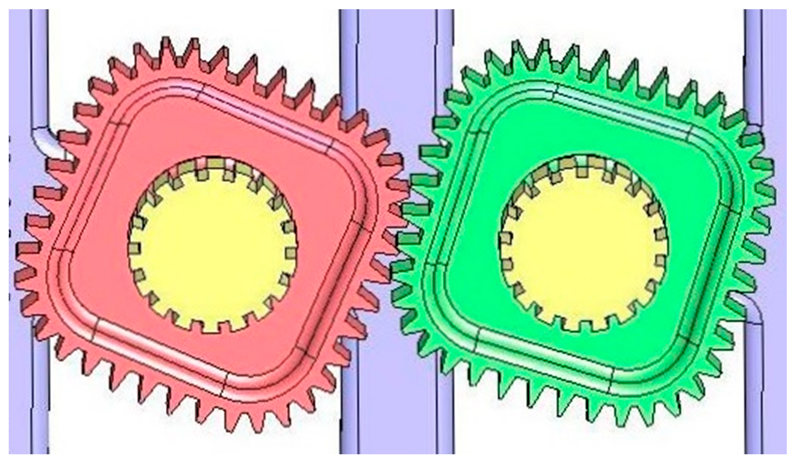
The idea of non-circular gears dates from the early history of engineering. Leonardo da Vinci sketched some spatial versions of non-circular gears. In the 18th century, non-circular gears were used in flow pumps (Figure 1), clocks, music boxes, toys, and other devices. At the end of the 19th century, Franz Reuleaux ordered a series of non-circular gear-type mechanisms from the Gustav Voigt Mechanische Werkstatt in Berlin. Those mechanisms were designed to be used in the study of kinematics. Gears manufactured at that time had simplified shapes, which led to inappropriate meshing conditions, as shown, in Figure 2.
At present, non-circular gears and toothed cams are used in textile machines, non-linear potentiometer drives, continuously variable transmissions, transportation lines, Geneva indexing devices, and other mechanisms. Although modern computer numerical control (CNC)-controlled machines enable the manufacture of complex shapes, appropriate non-circular gear design methods are not readily available and usually the simplest elliptical gears are used.
Many academics around the world are interested in non-circular gears, including researchers working in Sweden, Russia, USA, Hungary, and Poland. Regardless, development in the field has been slow due to the complicated nature of equations describing non-circular gears [1,2,3]. This complexity has made the analysis of non-circular gears virtually impossible without the aid of computer technology [4,5,6].
Compared with standard gears, the design and manufacture of non-circular gears with parallel axes involve several additional problems. The most important of those problems are:
  • the calculation of roll lines for both members that work properly together, i.e., rolling without slipping [7,8], and
  • the calculation of cooperating tooth forms for which the meshing pole and reference rack’s roll lines change their positions over time. Additionally, in non-circular gears, each tooth’s flank has an independent baseline [9].
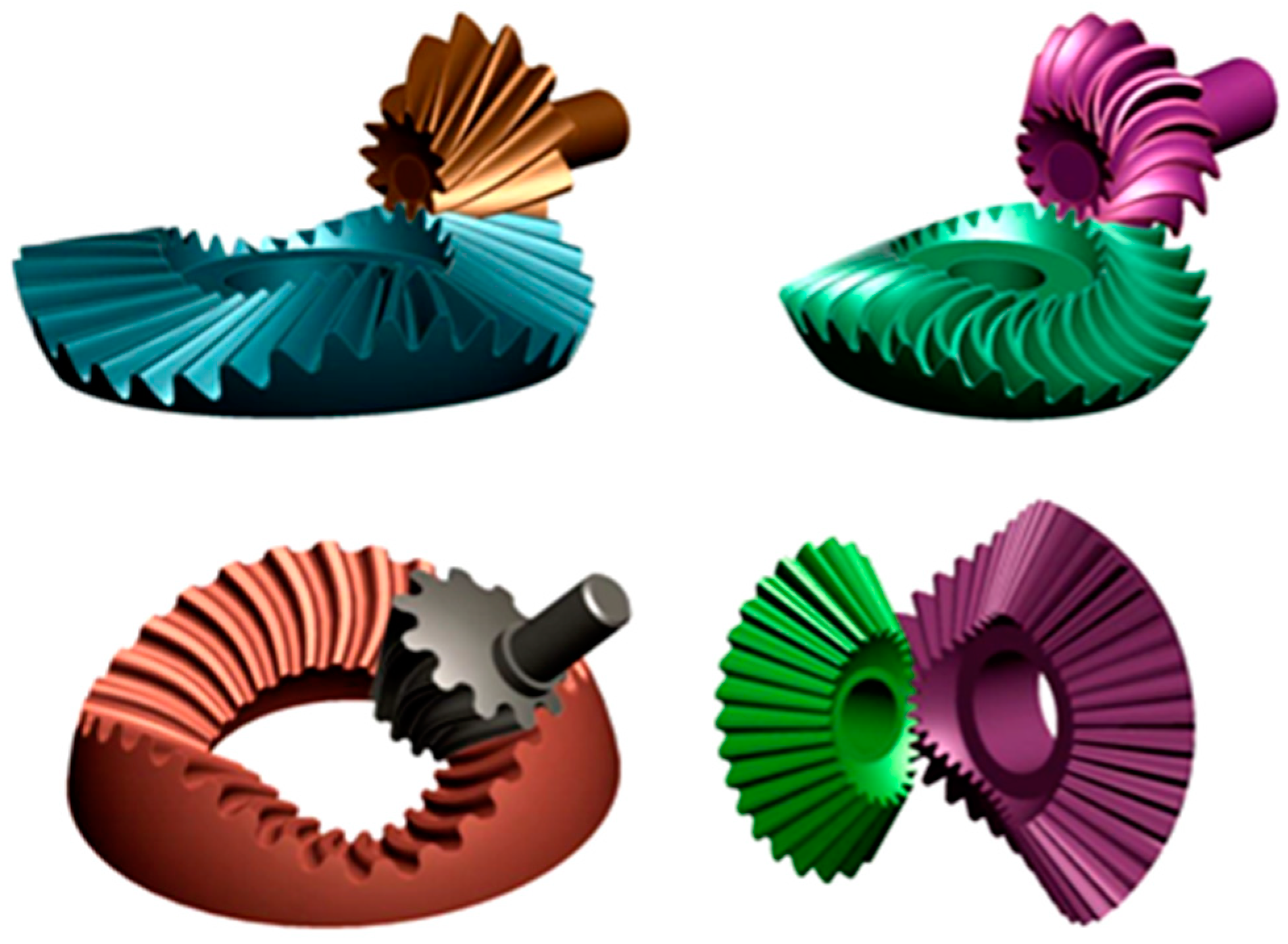
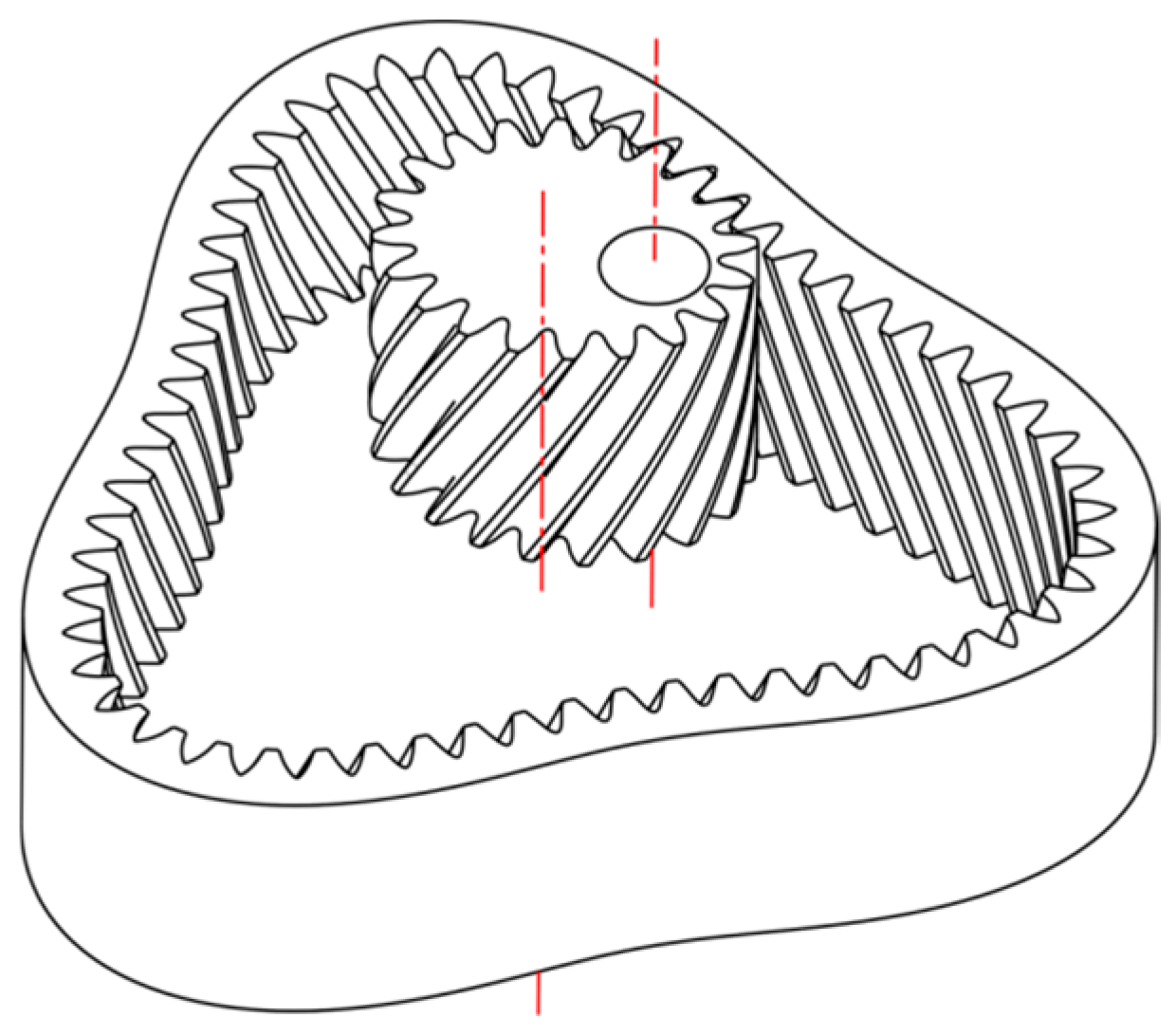
Modern manufacturing methods allow for the generation of non-circular bevel gears with free-form tooth profiles and curvilinear teeth in their lengthwise direction (Figure 3) [10]. These methods are also used in the manufacture of internal gears (Figure 4) [4].

2. Methods of Manufacturing Non-Circular Gears

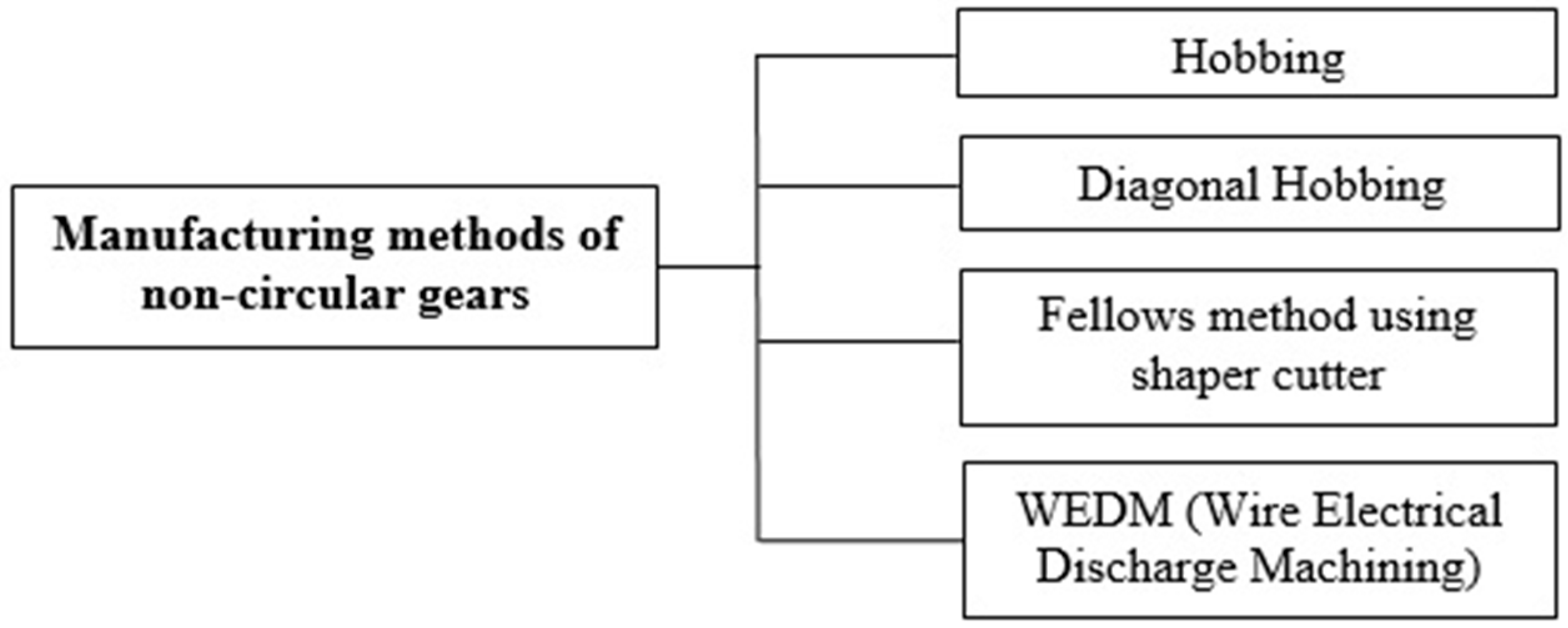
Basic manufacturing methods of non-circular gears are shown in Figure 5.

3. Diagonal Hobbing of a Non-Circular Gear

Previous studies [12,13] described a strategy for machining non-circular gears using the diagonal hobbing method.
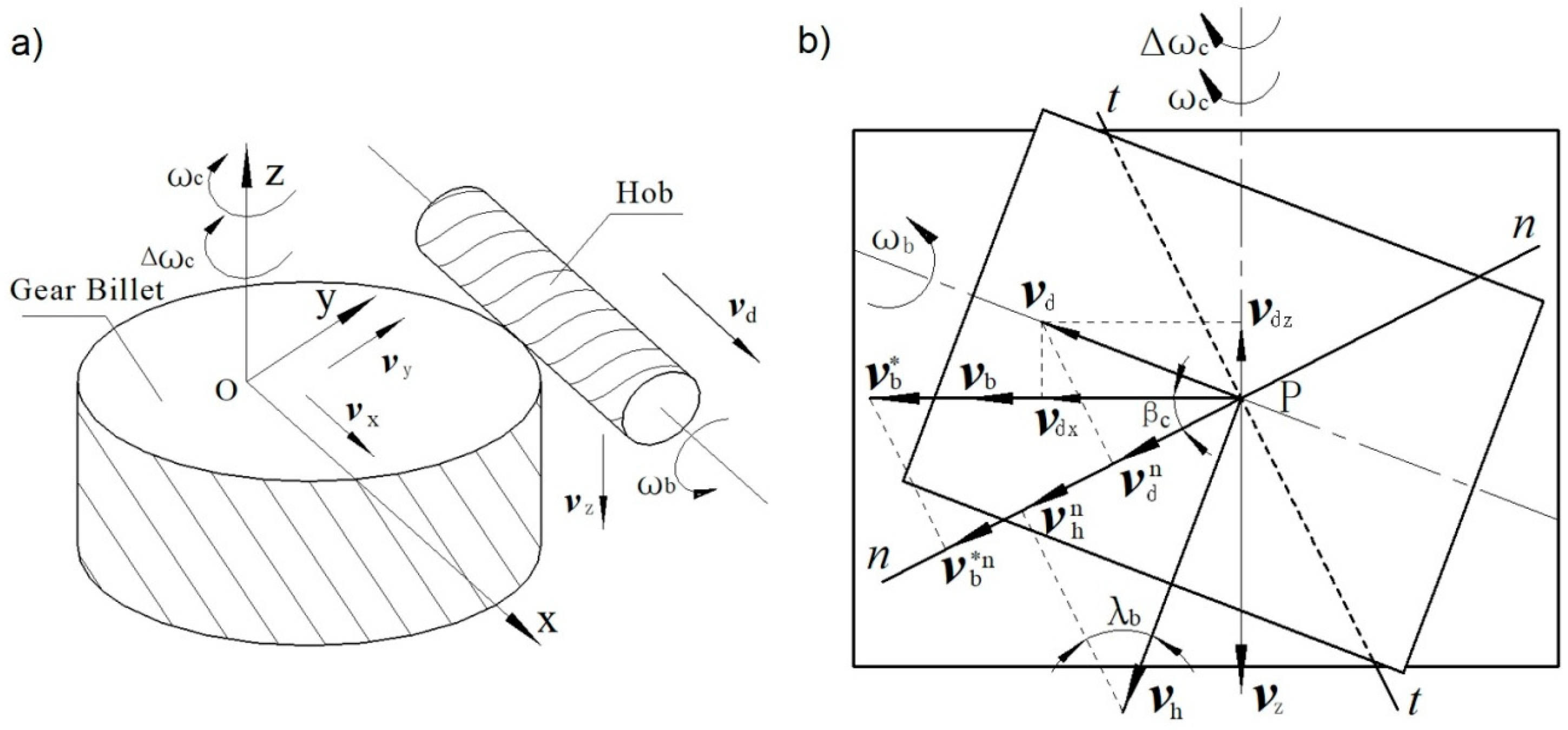
When hobbing non-circular helical gears, issues affecting the cutter teeth of the hob include uneven load and wear. To solve these problems, a simultaneous six-axis hobbing model was developed based on diagonal hobbing (Figure 6). Linkage models and their strategies were verified by hobbing testing. Experimental results showed that diagonal hobbing has several advantages over non-diagonal hobbing. Specifically, the hob life is 3.68 times longer with the diagonal hobbing method than with non-diagonal hobbing, and the micro-topography in the surface of the teeth is more stable during transmission with the diagonal hobbing method.
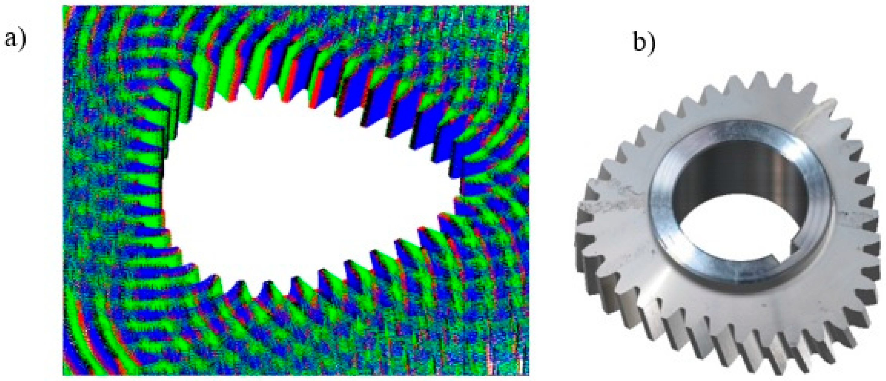
A schematic diagram and a kinematic representation of this hobbing method are shown in Figure 7. In addition, the amount of wear observed with diagonal hobbing was smaller than that observed with non-diagonal hobbing (Figure 8).

4. Machining of a Non-Circular Gear Using the Fellows Method and a Shaper Cutter

The Warsaw University of Technology developed an innovative method of forming non-circular gears using the Fellows method [14,15]. This method is used in situations in which other methods do not allow the machining of a concave profile [16,17].
A kinematic model of teeth shaping using this method is shown in Figure 9.
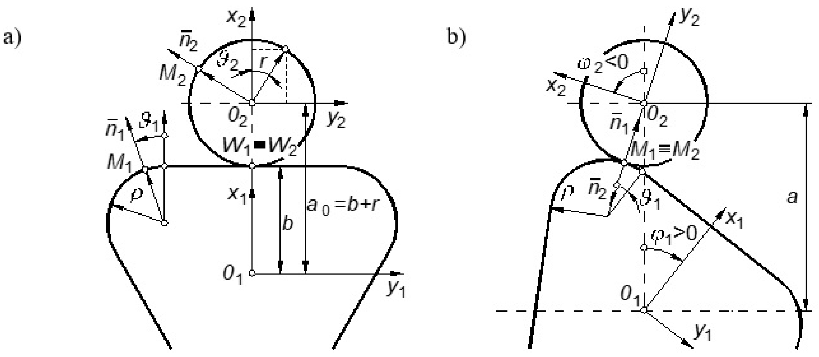
Let us consider two curves rolling on each other without sliding (Figure 10). The first curve is rigidly connected with the coordinate system x 1 ,   O 1 ,   y 1 rotating with constant angular velocity by the angle ϕ 1 . The second curve is rigidly connected with the coordinate system x 2 ,   O 2 ,   y 2 rotating with variable angular velocity by the angle ϕ 2 . Both curves may be described in their own systems using variable parameters ϑ 1 ,   ϑ 2 as:
x 1 = x 1 ( ϑ 1 ) y 1 = y 1 ( ϑ 1 ) }   or   r ¯ 1 = [ x 1 ( ϑ 1 ) y 1 ( ϑ 1 ) ]
x 2 = x 2 ( ϑ 2 ) y 2 = y 2 ( ϑ 2 ) }   or   r ¯ 2 = [ x 2 ( ϑ 2 ) y 2 ( ϑ 2 ) ]
and vector [ a 0 ] represents the center distance in the transmission.
In the general case, the center distance a is also variable (Figure 9), although in a specific case, it can be constant. The task is to compute the kinematic functions ϕ 2 = f 1 ( ϕ 1 ) and a 2 = f 2 ( ϕ 1 ) describing the relative motions (rotational and rectilinear) of both gears.
To solve this task, let us consider any two points M1, M2 being in contact. Let us take as an example the part of a hydraulic motor transmission consisting of a toothed triangle rotor (with rounded corners) and a circular satellite. The roll curves are shown in Figure 10.
They can be described as follows:
  • Circular rolling curve of the satellite:
    x 2 = r   cos ϑ 2 y 2 = r   sin ϑ 2 }
    n ¯ 2 = [ n x 2 n y 2 ] =   [ cos ϑ 2 sin ϑ 2 ]
  • Rectilinear part of the triangle:
    x 1 = b = c o n s t y 1 = y 1 ( equivalent   of   variable   parameter     ϑ 1 ) }
  • Rounded corners of the triangle (point M 1 in Figure 4):
    x 1 = b ρ ( 1 cos ϑ 1 ) y 1 = [ ( b ρ ) ctg 30 0 + ρ   sin ϑ 1 ] }
    n ¯ 1 = [ n x 1 n y 1 ] = [ cos ϑ 1 sin ϑ 1 ]
Equations of rolling curves and normal vectors are the starting point for determining the coordinates of tooth profiles [14].

5. Machining of a Non-Circular Gear Using the WEDM Method

An innovative method of modeling the machining of non-circular gears using the wire electrical discharge machining (WEDM) method was developed at the Warsaw University of Technology with the participation of the author of this article—Tadeusz Sałaciński [9,18]. García-Hernández et al. [19] also examined this problem.
In Figure 11, the non-circular gear in design is represented as two roll lines P1 and P2 with rotation centers at points O1 and O2, respectively. Those lines work together, rolling without slipping.
The shape P1 is described by a polar equation as a function of radius r1(ϕ1). The gear ratio is described by the function:
ν ( ϕ 1 ) = ω 1 ( ϕ 1 ) ω 2 ( ϕ 1 ) = r 2 ( ϕ 1 ) r 1 ( ϕ 1 )
where ω1(ϕ1) and ω2(ϕ2) are angular velocity functions of the first and the second gears, respectively.
The axle distance A is constant:
A = r 1 ( ϕ 1 ) + r 2 ( ϕ 1 ) = c o n s t
The roll lines work together without slipping:
d ϕ 2 = r 1 ( ϕ 1 ) r 2 ( ϕ 1 ) d ϕ 1
Taking Equations (8) to (10) into account and integrating
ϕ 2 = 0 ϕ 1 r 1 ( ϕ 1 ) A r 1 ( ϕ 1 ) d ϕ 1 ,
the integrating constant was found from the following condition: if ϕ1 = 0, then ϕ2 = 0.
Note that to continuously transfer the motion, the gear ratio function must be periodic and the gear’s period T must be related to periods T1 and T2 of gears 1 and 2, respectively, as follows:
T = T 1 n 2 = T 2 n 1
where n1 and n2 are natural numbers.
In the case shown in Figure 11, the period T of the gear ratio function ν(ϕ1) = π, T1 = 2π, and T2 = 3π; therefore, when ϕ1 = π, then ϕ2 = 2/3π. This renders:
2 3 π = 0 π r 1 ( ϕ 1 ) A r 1 ( ϕ 1 ) d ϕ 1
The value of the parameter A can be calculated from Equation (13). The P2 = r21) can be calculated from Equations (9) and (10).
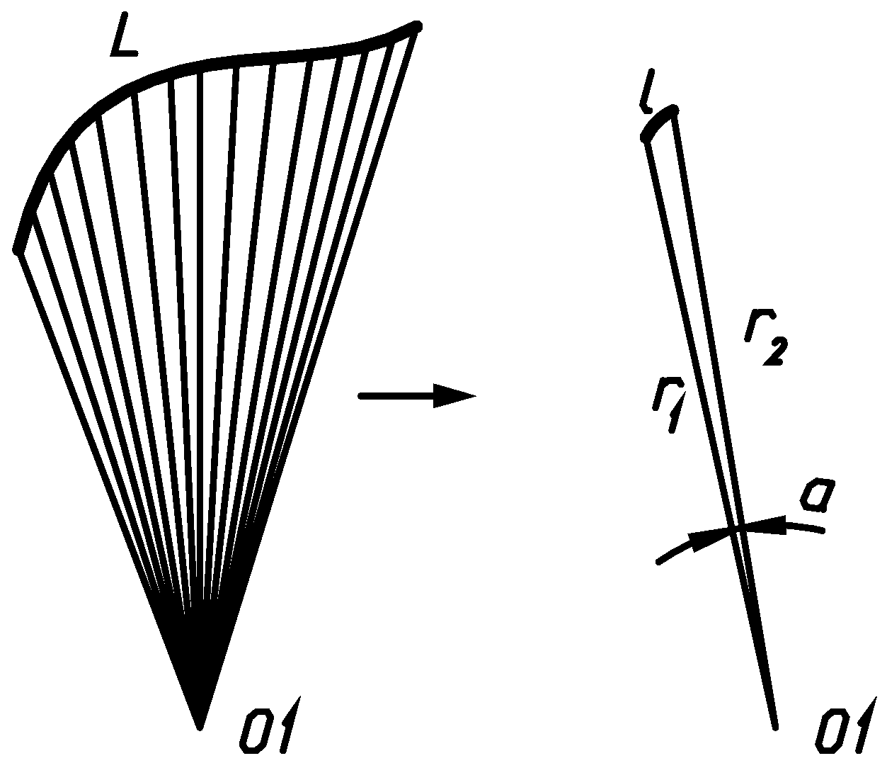
We assume there is roll line P1 for which a cooperating line P2 needs to be found that fulfils the requirements described above. The line P1 has been divided into i segments l1i so that each of those segments can be represented as an Archimedes spiral with adequate precision (Figure 12).
An Archimedes spiral is described by:
r = k α
Therefore:
α 1 = r 1 k ;   α 2 = r 2 k ; k = r 2 r 1 α d l = ( d r ) 2 + ( r d α ) 2 ; d r = d ( k α ) = k d α d l = ( k d α ) 2 + ( r d α ) 2 = ( k d α ) 2 + ( k α d α ) 2 = k 1 + α 2 d α d l = k 2 [ α α 2 + 1 + ln ( α + α 2 + 1 ) ] l = α 1 α 2 d l = k 2 [ α 2 α 2 2 + 1 + ln ( α 2 + α 2 2 + 1 ) α 1 α 1 2 + 1 ln ( α 1 + α 1 2 + 1 ) ]
If lines P1 and P2 are rolling together without slipping, and line P2 has been divided into i parts l2i accordingly to P1, then, with reference to Equations (10), we get:
l 1 i = l 2 i
The equation of the line P2 is evaluated from Equations (9) to (16).
The next step is to calculate the tooth forms. For this purpose, the context analysis method was used. In this method, the system under examination is transformed through its states and data are collected, forming a context. Then the data that meet defined requirements are filtered out of the context.
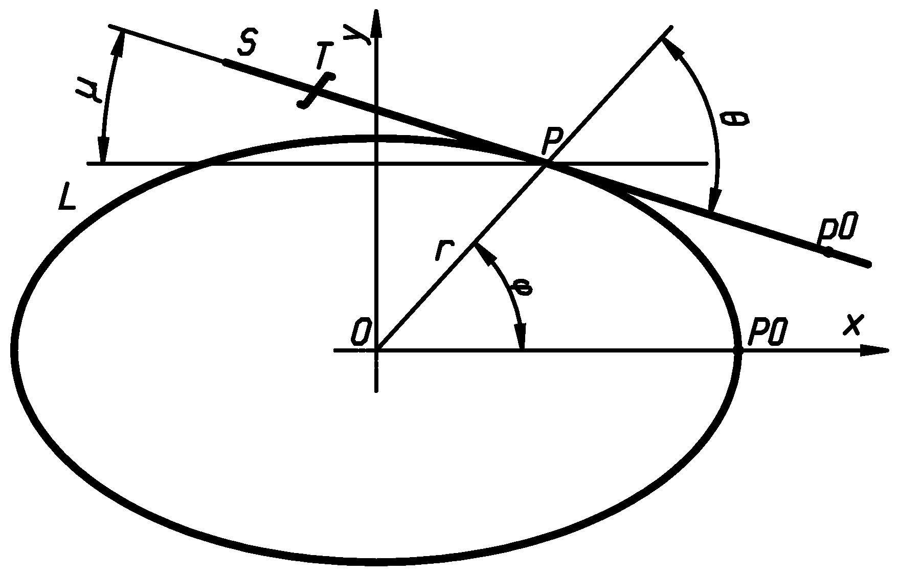
The roll line of a non-circular gear is described by L = r(ϕ). There is a reference rack guide S rolling over the gear’s line without slipping. A reference rack’s profile T is bound up with the S line (Figure 13). The coordinates of the lines’ contact point P are:
P [ x , y ] = [ r ( ϕ ) cos ( ϕ ) , r ( ϕ ) sin ( ϕ ) ]
An angle between the r(ϕ) radius and the reference rack’s guide S is calculated from:
θ = arctan ( r ( ϕ ) d r d ϕ )
So:
μ = ϕ θ
If ϕ = 0 then P0 = p0. Since the guide S is rolling over the line L without slipping from point P0 to point P, the length of a segment l of line L between points P0 and P equals the length of a vector s between points p0 and P of the S line.
If the line L is composed of i Li segments according to the requirements listed above, the point P corresponds to Lj, and li lengths and ki coefficients are found for each Li segment from Equation (15), then:
d r d ϕ = k j | s | = n = 1 j l n .
Figure 14 shows the consecutive positions of the roll line Sj to Sk and of the reference rack’s profile Tj to Tk.
To find the points of a non-circular gear tooth’s form, the lines u1 to uz were introduced. The intersection points of the profiles Tj to Tk with the lines u1 to uz were calculated using analytic geometry. The points lying on a non-circular gear tooth’s form were filtered out from all the points that were found. This procedure was repeated for all the flanks of the non-circular gear. The module of the non-circular gear is calculated using:
m = | L | π z = n = 1 i l n π z
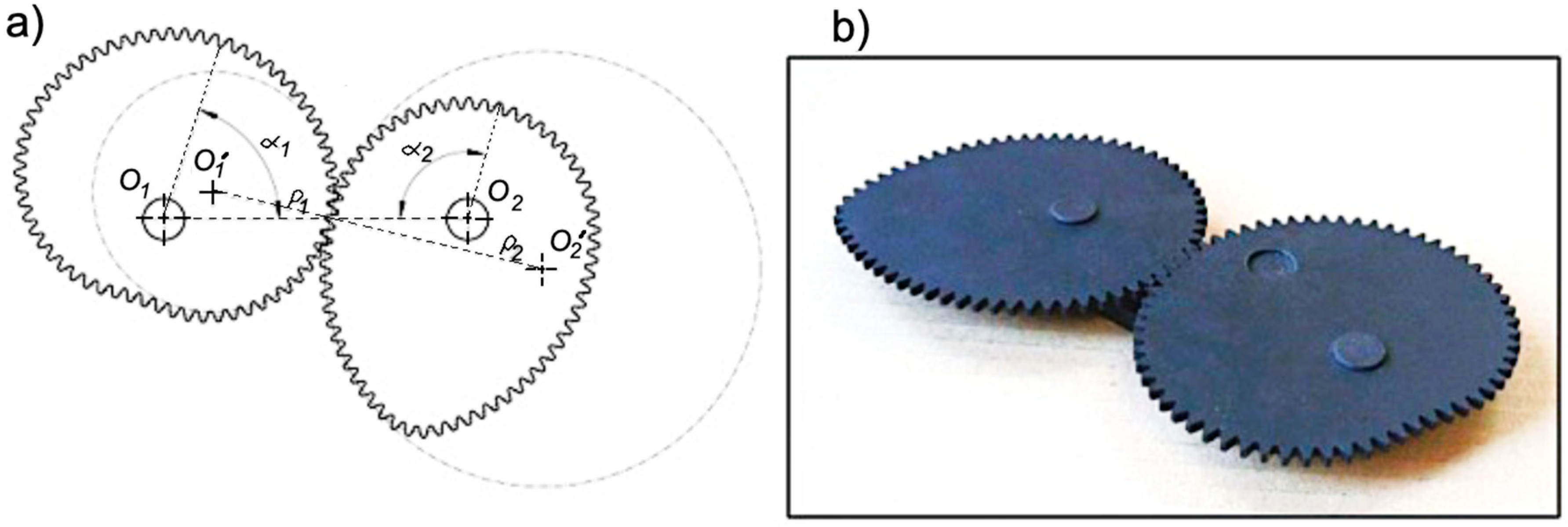
where z is the number of teeth in the gear. An example model of a non-circular gear and a machined gear are shown in Figure 15.
This numerical model was used to create the manufacturing programs for a CNC-controlled wire electrical discharge machine. The gears were compared with a digital model using the coordinate measuring machine (CMM). A scan of the tooth flanks was performed and the scans were verified against the mathematical master using computer software developed because the CMM lacked the functionality.
The measuring reports showed that the form error r measured on various tooth heights h was less than 0.02 mm, which corresponds to class 8 of the Deutsches Institut für Normung (DIN) 3962 guidelines (Figure 16).
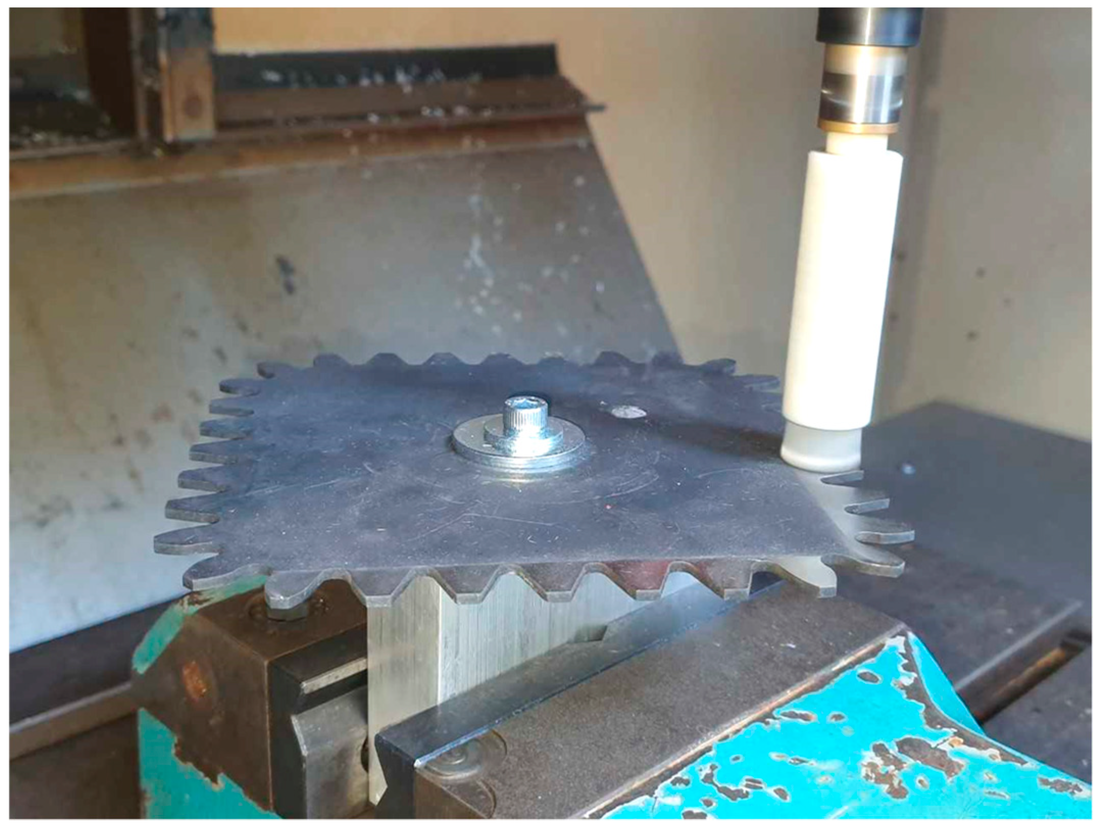
As a result of machining non-circular gears on their faces, unfavorable burrs are formed. These can be removed with rotary brushes with ceramic fibers (Figure 17) [20,21,22,23,24].
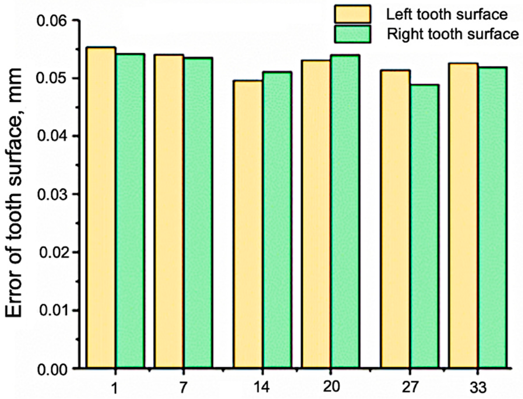
The problems associated with accuracy and machining times for the methods analyzed in this article are not sufficiently discussed in the literature. Liu et al. [25] assessed the accuracy of the machining of a non-circular gear (modulus (m) was 3, number of teeth (z) was 39, and tooth width (b) was 30 mm) using the hobbing method (Figure 18). The geometrical accuracy of the surface was observed to be at the level of 0.05–0.06 mm.
In our opinion, the machining times for non-circular gears are comparable to those for classic circular gears. This will be the subject of further research.

6. Conclusions

This paper describes the technological aspects of different methods of manufacturing non-circular gears. The most efficient method is hobbing, but this method cannot be used in all cases (e.g., for concave tooth lines). Internal teeth are machined using the Fellows method or the WEDM method. The WEDM method enables the implementation of custom shapes for the undercut sections at the feet of the teeth and those sections can be different for each flank. Because the WEDM method is an expensive process, it is most often used for low volume production. For series production, other manufacturing methods, such as the Fellows method, may be beneficial. However, a disadvantage of this process is the need for unconventional machines and the complicated geometry of the tools. The meshing conditions in a non-circular technological gear are different in each phase of its generation, which causes the tool requirements to change. The main issues with this process are the form diameters, interference, and changes in the parameters after the re-sharpening of a tool. For these reasons, WEDM may prove to be the only technology available that allows manufacturing of a proper non-circular gear.
With the development of technologies using computer numerical control (CNC), non-circular gears are increasingly used in practice and have been the subject of research for many years. This is evident from publications (e.g., [25,26,27,28,29]) that reference computer simulations and 3D modeling. Further research should examine the geometric and kinematic accuracy, as well as the strength, of non-circular gears manufactured through different methods.
The results presented here may form the groundwork for further investigations of properties particular to non-circular gears. Similar investigations have been conducted with spur, helical, and bevel gears. Examples of properties particular to non-circular gears include kinematics, applications of special-purpose gears, as well as issues related to strength, dynamics, and tribology.

Author Contributions

Conceptualization, T.S. and T.C.; methodology, T.S.; validation, T.S., A.P.; formal analysis, T.C.; investigation, T.S.; resources, A.P.; writing—original draft preparation, T.S.; writing—review and editing, T.C.; visualization, A.P.; supervision, T.S. All authors have read and agreed to the published version of the manuscript.

Funding

This research received no external funding.

Conflicts of Interest

The authors declare no conflicts of interest.

References

  1. Chang, S.L.; Tsay, C.B. Computerised Tooth Profile Generation and Undercut Analysis of Noncircular Gears Manufactured with Shaper Cutters. ASME J. Mech. Des. 1998, 120, 92–99. [Google Scholar] [CrossRef]
  2. Doege, E.; Hindersmann, M. Optimized kinematics of mechanical presses with non-circular gears. CIRP Ann. 1997, 46, 213–216. [Google Scholar] [CrossRef]
  3. Doege, E.; Meinen, J.; Neumaier, T.; Schaprian, M. Numerical design of a new forging press drive incorporating non-circular gears. Proc. Inst. Mech. Eng. Part B J. Eng. Manuf. 2001, 215, 465–471. [Google Scholar] [CrossRef] [Green Version]
  4. Zheng, F.; Hua, L.; Hua, L.; Han, X.; Li, B.; Chen, D. Synthesis of Shaped Noncircular Gear Using a Three-Linkage Computer Numerical Control Shaping Machine. J. Manuf. Sci. Eng. 2017, 139, 071003. [Google Scholar] [CrossRef]
  5. Koć, A. Non-circular gears. Cutting tool selection and design. Adv. Manuf. Sci. Technol. 2001, 25, 49–59. [Google Scholar]
  6. Koć, A. Making out-of-round toothed wheels by means of numerically controlled slotting machines, Mathematical fundamentals for creating CAM software. Mechanik 2001, 74, 96–97. [Google Scholar]
  7. Laczik, B. Design and Manufacturing of Non-Circular Gears by Given Transfer Function. Available online: http://www.hexagon.de/pdf/noncgear.pdf (accessed on 12 October 2019).
  8. Laczik, B. Involute Profile of Non-Circular Gears. Institute of Mechanical Engineering; College of Dunaújváros: Dunaújváros, Hungary, 2008; Volume 126. [Google Scholar]
  9. Zarębski, I.; Sałaciński, T. Designing and WEDM manufacturing of non-circular gears. In Proceedings of the APE Conference, Warsaw, Poland, 21 April 2007. [Google Scholar]
  10. KMODDL. Available online: http://kmoddl.library.cornell.edu (accessed on 3 February 2020).
  11. Zheng, F.; Hua, L.; Han, X.; Chen, D. Generation of Noncircular Bevel Gears with Free-Form Tooth Profile and Curvilinear Tooth Lengthwise. J. Mech. Des. 2016, 138, 064501. [Google Scholar] [CrossRef]
  12. Liu, Y.; Han, J.; Xia, L.; Tian, X. Hobbing Strategy and Performance Analyses of Linkage Models for Non-Circular Helical Gears Based on Four-Axis Linkage. Stroj. Vestn.-J. Mech. Eng. 2012, 58, 701–708. [Google Scholar] [CrossRef] [Green Version]
  13. Liu, Y.; Diao, J. Six-Axis Linkage Strategy and Its Models for Non-Circular Helical Gears Based on Diagonal Hobbing. Stroj. Vestn.-J. Mech. Eng. 2015, 61, 330–342. [Google Scholar] [CrossRef]
  14. Koć, A. Manufacturing of non-circular gears on CNC Fellows Machines. In Proceedings of the Annals of MTeM for 2001&Proceedings of the 5th International MTeM Symposium, Cluj-Napoca, Romania, 4–6 October 2001; MTeM: Austin, TX, USA, 2001. [Google Scholar]
  15. Koć, A. Mathematical simulation for tooth machining of non-circular gears using Fellows-shapers. In Proceedings of the International Conference Advances in Production Engineering APE 2001, Warsaw, Poland, 7–9 June 2001. [Google Scholar]
  16. Li, J.G.; Mao, S. Numerical computing method of noncircular gear tooth profiles generated by shaper cutters. Int. J. Adv. Manuf. Technol. 2007, 33, 1098–1105. [Google Scholar] [CrossRef]
  17. Gao, T.; Han, J.; Tian, X.; Xia, L. Machining method with evenly distributed allowance based on the normal linkage model of non-circular gear shaping. INMATECH-Agric. Eng. 2017, 53, 113–122. [Google Scholar]
  18. Zarębski, I.; Sałaciński, T. Designing of non-circular gears. Arch. Mech. Eng. 2008, LV, 275–292. [Google Scholar]
  19. García-Hernández, C.; Gella-Marín, R.M.; Huertas-Talón, J.L.; Efkolidis, N.; Kyratsis, P. WEDM Manufacturing Method for Noncircular Gears, Using CAD/CAM Software. Stroj. Vestn.-J. Mech. Eng. 2016, 62, 2. [Google Scholar] [CrossRef] [Green Version]
  20. Salacinski, T.; Winiarski, M.; Chmielewski, T.; Swiercz, R. Surface finishing with ceramic fibre brush tools. In Proceedings of the International Conference METAL 2017, Brno, Czech Republic, 24–26 May 2017. [Google Scholar]
  21. Sałaciński, T.; Chmielewski, T.; Winiarski, M.; Cacko, R.; Świercz, R. Roughness of Metal Surface after Finishing Using Ceramic Brush Tools. Adv. Mater. Sci. 2018, 18, 20–27. [Google Scholar] [CrossRef] [Green Version]
  22. Sałaciński, T.; Winiarski, M.; Przesmycki, A.; Świercz, R.; Chmielewski, T. Applying titanium coatings on ceramic surfaces by rotating brushes. In Proceedings of the METAL 2018—27th International Conference on Metallurgy and Materials, Conference Proceedings, Brno, Czech Republic, 23–25 May 2018. [Google Scholar]
  23. Świercz, R.; Oniszczuk-Świercz, D.; Chmielewski, T. Multi-response optimization of electrical discharge machining using the desirability function. Micromachines 2019, 10, 72. [Google Scholar] [CrossRef] [Green Version]
  24. Świercz, R.; Oniszczuk-Świercz, D.; Chmielewski, T.; Sałaciński, T. Investigations on surface integrity processed by EDM. In Proceedings of the METAL 2018—27th International Conference on Metallurgy and Materials, Conference Proceedings, Brno, Czech Republic, 23–25 May 2018. [Google Scholar]
  25. Liu, Y.; Liao, F.; Dong, C. Research on Tooth Profile Error of Non-Circular Gears Based on Complex Surface Theory; Springer Nature Singapore Pte Ltd.: Singapore, 2020. [Google Scholar]
  26. Korzeniewski, H. Uzębienie ewolwentowe kół trochoidalnych. Arch. Technol. Masz. Autom. 2006, 26, 159–167. [Google Scholar]
  27. Kowalczyk, K.L.; Urbanek, U.S. The geometry and kinematics of a toothed gear of variable motion. Fibres Text. East. Eur. 2003, 11, 60–62. [Google Scholar]
  28. Smith, W.C. The Math of Noncircular Gearing. Gear Technology, July/August, 2000. Available online: https://www.geartechnology.com/issues/0700x/smith.pdf (accessed on 21 February 2019).
  29. Litvin, F.L.; Gonzalez-Perez, I.; Fuentes, A.; Hayasaka, K. Design and investigation of gear drives with non-circular gears applied for speed variation and generation of functions. Comput. Methods Appl. Mech. Eng. 2008, 197, 3783–3802. [Google Scholar] [CrossRef]
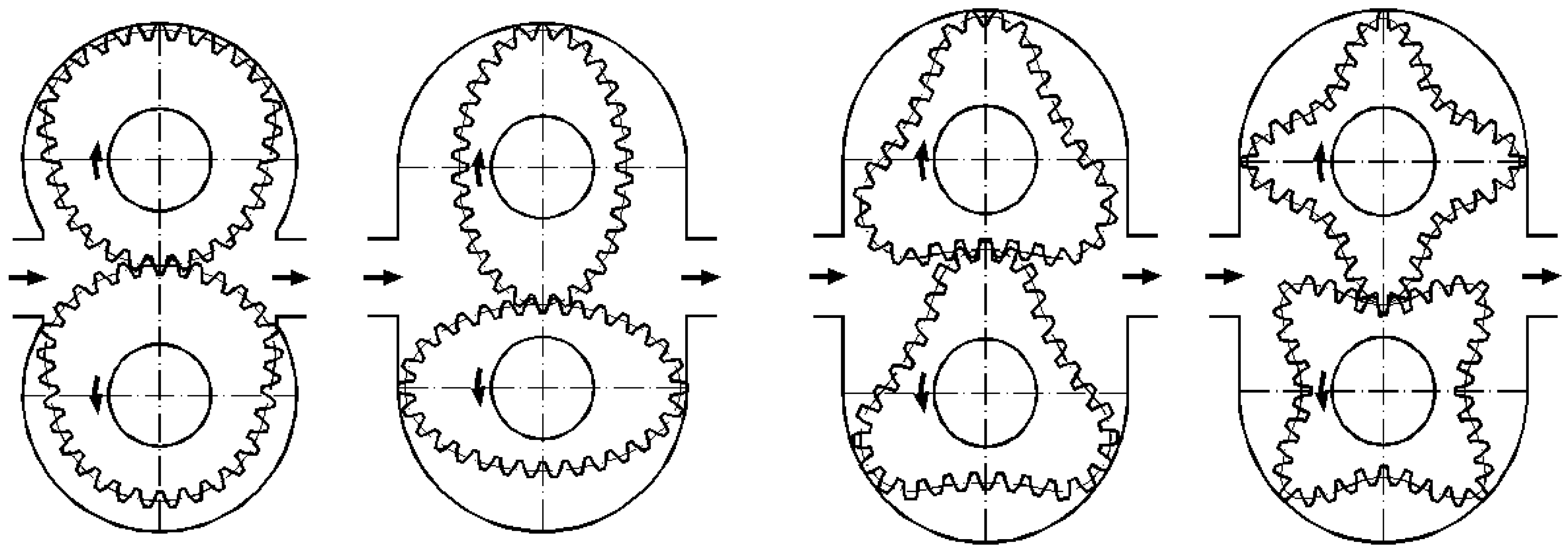
Figure 1. Examples of flow pumps using non-circular gears.
Applsci 10 03420 g001
Figure 2. Historical model of non-circular gear [10].
Applsci 10 03420 g002
Figure 3. Examples of non-circular bevel gears with free-form tooth profiles and curvilinear teeth in their lengthwise direction [11].
Applsci 10 03420 g003
Figure 4. Example of non-circular bevel internal gears [4].
Applsci 10 03420 g004
Figure 5. Manufacturing methods of non-circular gears.
Applsci 10 03420 g005
Figure 6. (a) Schematic diagram of the hobbing process; (b) common tangent plane of hobbing. ωc: angular velocity, Δωc: extra angular velocity, vd: diagonal feed rate, v: velocity, ωb: lead angle, βc: helical angle [12].
Applsci 10 03420 g006
Figure 7. (a) Virtual hobbing of a non-circular helical gear based on the diagonal hobbing process; (b) 3-order elliptic helical gear hobbed using diagonal hobbing [12].
Applsci 10 03420 g007
Figure 8. Wear width of flank surface for two kinds of hobbing [12].
Applsci 10 03420 g008
Figure 9. Examples of technological transmission for a shaper and a non-circular gear [14,15].
Applsci 10 03420 g009
Figure 10. The roll curves of a hydraulic motor: (a) At the beginning ( ϕ 1 = 0 ); (b) after rotation of the triangle rotor by any angle ϕ 1 [14,15].
Applsci 10 03420 g010
Figure 11. Roll lines representing a non-circular gear; P1, P2—roll lines, O1, O2—rotation centers.
Applsci 10 03420 g011
Figure 12. Roll line divided into segments.
Applsci 10 03420 g012
Figure 13. A reference rack guide over the roll line of a gear.
Applsci 10 03420 g013
Figure 14. Evaluation of a tooth’s form.
Applsci 10 03420 g014
Figure 15. (a) Model of a non-circular gear; (b) machined gear.
Applsci 10 03420 g015
Figure 16. CMM (Coordinate Measuring Machine) measuring report.
Applsci 10 03420 g016
Figure 17. Deburring of a non-circular gear with rotary brushes with ceramic fibers.
Applsci 10 03420 g017
Figure 18. Errors of the tooth surface in the hobbing method [25].
Applsci 10 03420 g018